Embed Size (px)
DESCRIPTION
This paper presents design and modelling of car front suspension lower arm to study the stress condition and to increase thickness of lower plate of the front suspension lower arm. The main objectives of this study to determine critical locations and strain distributions of the component.The paper aims to complete Finite Element Analysis of the front suspension lower arm which consist the stress optimization loadings and analysis for deformation.
Citation preview
IJIRST –International Journal for Innovative Research in Science & Technology| Volume 2 | Issue 02 | July 2015 ISSN (online): 2349-6010
All rights reserved by www.ijirst.org 249
Design and Modeling of Car Front Suspension
Lower Arm
Mr. Sushilkumar P. Taksande Dr. A.V.Vanalkar
Student Professor
Department of Mechanical Engineering Department of Mechanical Engineering
K.D.K.C.E. Nagpur, India K.D.K.C.E. Nagpur, India
Abstract
This paper presents design and modelling of car front suspension lower arm to study the stress condition and to increase
thickness of lower plate of the front suspension lower arm. The main objectives of this study to determine critical locations and
strain distributions of the component.The paper aims to complete Finite Element Analysis of the front suspension lower arm
which consist the stress optimization loadings and analysis for deformation.
Keywords: Lower Suspension arm, vehicle, modeling,
_______________________________________________________________________________________________________
I. INTRODUCTION
The suspension arm gets more attention by many researches like study dynamic analyses of the motor vehicle suspension system
using the point-joint coordinate’s formulation. The mechanical system is replaced by an equivalent constrained system of
particles and then the laws of particle dynamics are used to derive the equations of motion. Modeling and simulation are
indispensable when dealing with complex engineering systems. It makes it possible to do an essential assessment before systems
are developed. It can provide support in all stages of a project from conceptual design, through commissioning and operation.
The most effective way to improve product quality and reliability is to integrate them in the design and manufacturing process.
Suspension arm is one of the main components in the suspension systems. It can be seen in various types of the suspensions
like wishbone or double wishbone suspensions. Most of the times it is called as A-type control arm. It joins the wheel hub to the
vehicle frame allowing for a full range of motion while maintaining proper suspension alignment. Uneven tyre wear, suspension
noise or misalignment, steering wheel shimmy or vibrations are the main causes of the failure of the lower suspension arm. Most
of the cases the failures are catastrophic in nature. So the structural integrity of the suspension arm is crucial from design point of
view both in static and dynamic conditions. As the Finite Element Method (FEM) gives better visualization of this kind of the
failures so FEM analysis of the stress distributions around typical failure initiations sites is essential. Therefore in this
dissertation work it is proposed to carry out the structural analysis of lower suspension arm of light commercial vehicle using
FEM
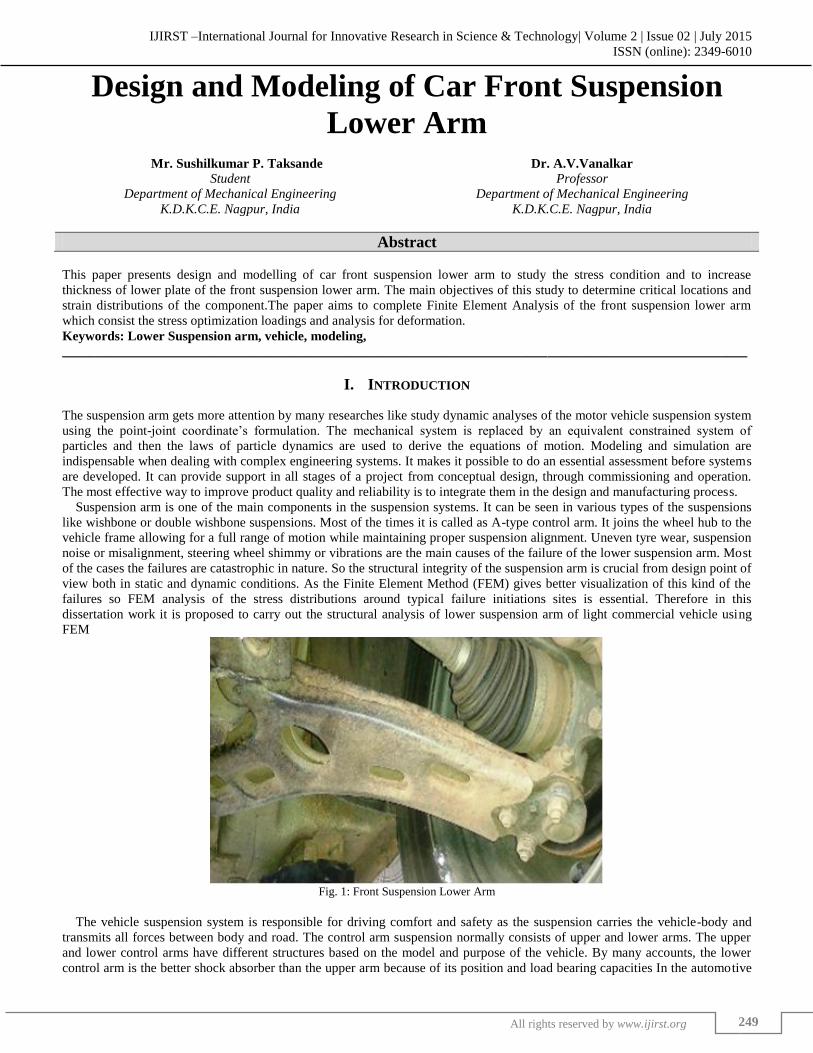
Fig. 1: Front Suspension Lower Arm
The vehicle suspension system is responsible for driving comfort and safety as the suspension carries the vehicle-body and
transmits all forces between body and road. The control arm suspension normally consists of upper and lower arms. The upper
and lower control arms have different structures based on the model and purpose of the vehicle. By many accounts, the lower
control arm is the better shock absorber than the upper arm because of its position and load bearing capacities In the automotive
Design and Modeling of Car Front Suspension Lower Arm (IJIRST/ Volume 2 / Issue 02/ 042)
All rights reserved by www.ijirst.org 250
industry, the riding comfort and handling qualities of an automobile are greatly affected by the suspension system, in which the
suspended portion of the vehicle is attached to the wheels by elastic members in order to cushion the impact of road
irregularities.
Objective A.
1) The main aim is to investigate the failure of the lower arm.
2) To describe a computer-based approach to the car front suspension design problem.
3) Study the existing component design and its function for identifying potential areas for modification
4) Evolve a Test plan for validating the F.E.A Methodology
5) Recommend the new design for implementation
6) To analysis of the suspension arm using ANSYS Software.
II. RESEARCH METHODOLOGY
In this project, we are using CAD and Analysis softwares like Creo-Parametric 2.0 and ANSYS Version 13.0. Here we can
prepare a CAD model of lower arm in Creo-Parametric 2.0 and determine the stress value and deform value in ANSYS 13.0. To
study various stresses and deform values is acting on lower arm. CAD model of lower arm is designed in Creo-Parametric 2.0
was imported in ANSYS software for meshing and different results. Meshed model of the lower arm essentially consist of nodes
and elements. Tetra elements give enhanced result as compared to other types of elements, therefore the elements used in this
analysis is tetra elements. The material Fe410 and Fe510 was used for lower control arm. Calculated forces and boundary
conditions were applied on meshed model in ANSYS 13.0. Static and modal analysis was performed by using ANSYS 13.0.
Design parameters obtained from above Finite Element Analysis were compared for above stated materials and best one was
selected.
Analytical Calculation A.
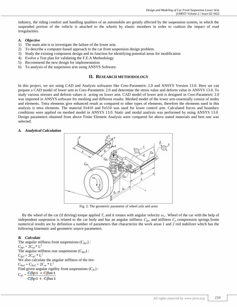
Fig. 2: The geometric parameter of wheel axle and arms
By the wheel of the car (if driving) torque applied Тк and it rotates with angular velocity ωк . Wheel of the car with the help of
independent suspension is related to the car body and has an angular stiffness Сβр, and stiffness Ср compression springs.Some
numerical results are by definition a number of parameters that characterize the work areas 1 and 2 rod stabilizer which has the
following kinematic and geometric source parameters.
Calculate B.
The angular stiffness front suspensions (Сβр1) :
Сβp1 = 2Cp1* L2
The angular stiffness rear suspensions (Сβр2) :
Сβp2 = 2Cp2 * L2
We also calculate the angular stiffness of the tire:
Сβш1 = Сβш2 = 2Сш * L2
Find given angular rigidity front suspensions (Сβ1) :
Сβ1 =
Design and Modeling of Car Front Suspension Lower Arm (IJIRST/ Volume 2 / Issue 02/ 042)
All rights reserved by www.ijirst.org 251
Find given angular rigidity rear suspensions (Сβ2):
Сβ2 =
Effective roll arm (h3) :
h3 = hg – h2 *
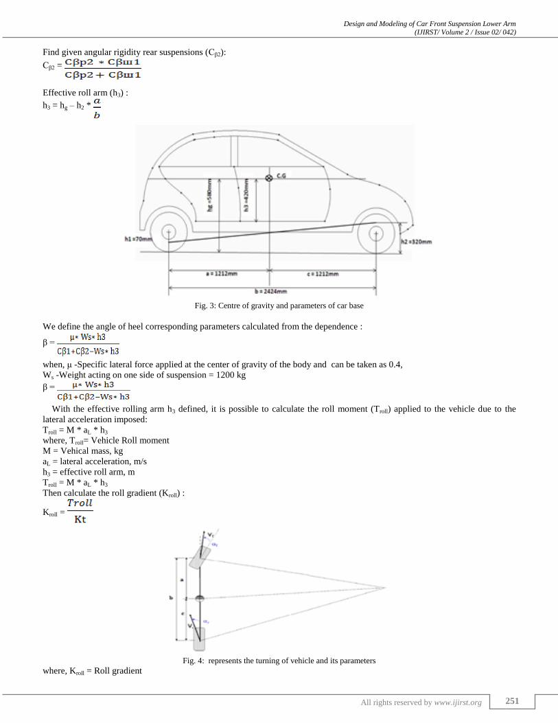
Fig. 3: Centre of gravity and parameters of car base
We define the angle of heel corresponding parameters calculated from the dependence :
β =
when, μ -Specific lateral force applied at the center of gravity of the body and can be taken as 0.4,
Ws -Weight acting on one side of suspension = 1200 kg
β =
With the effective rolling arm h3 defined, it is possible to calculate the roll moment (Troll) applied to the vehicle due to the
lateral acceleration imposed:
Troll = M * aL * h3
where, Troll= Vehicle Roll moment
M = Vehical mass, kg
aL = lateral acceleration, m/s
h3 = effective roll arm, m
Troll = M * aL * h3
Then calculate the roll gradient (Kroll) :
Kroll =
Fig. 4: represents the turning of vehicle and its parameters
where, Kroll = Roll gradient
Design and Modeling of Car Front Suspension Lower Arm (IJIRST/ Volume 2 / Issue 02/ 042)
All rights reserved by www.ijirst.org 252
Kt = Сβp1 = Vehicle’s total roll stiffness
The forces per axle can be calculated as follows :
Front axle force (Ffront):
Ffront = * M * aL
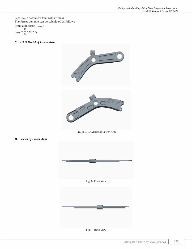
CAD Model of Lower Arm C.
Fig. 5: CAD Model of Lower Arm
Views of Lower Arm D.
Fig. 6: Front view
Fig. 7: Back view
Design and Modeling of Car Front Suspension Lower Arm (IJIRST/ Volume 2 / Issue 02/ 042)
All rights reserved by www.ijirst.org 253
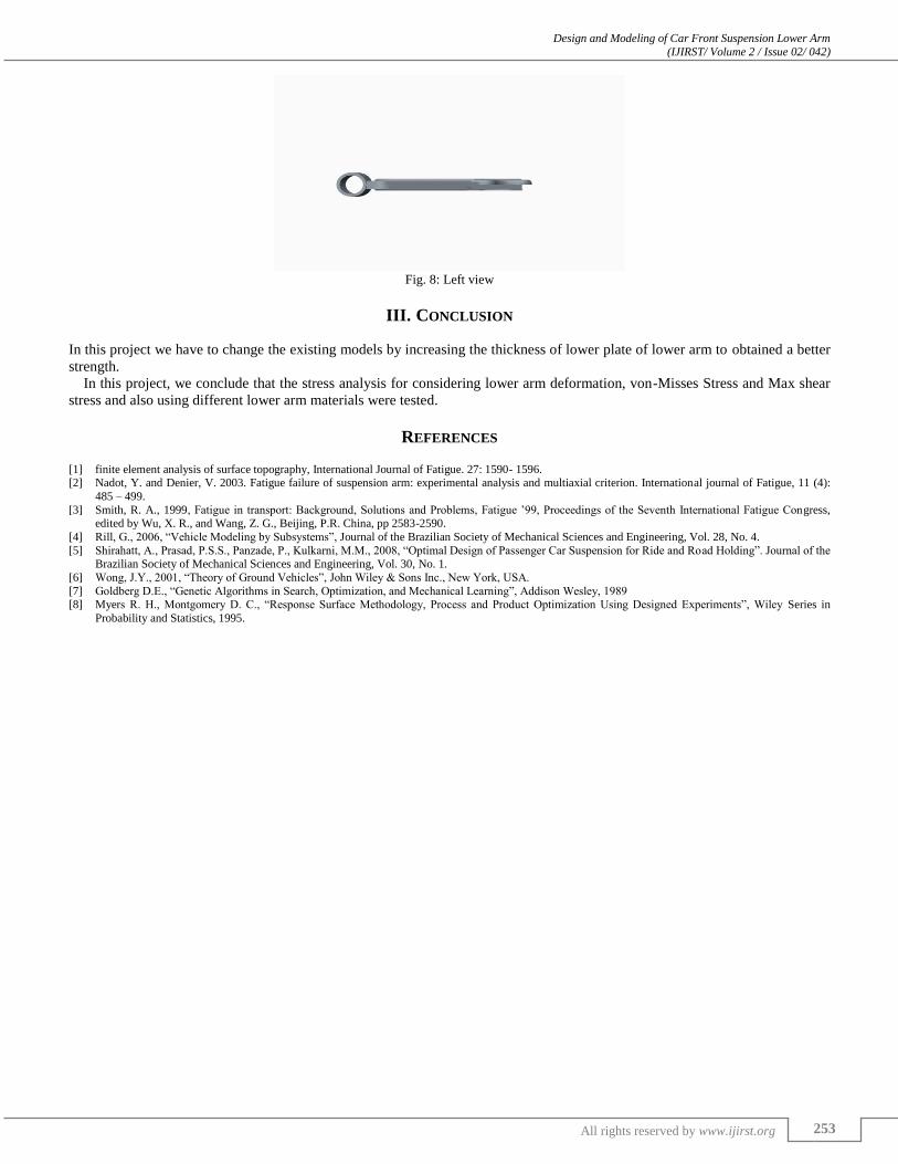
Fig. 8: Left view
III. CONCLUSION
In this project we have to change the existing models by increasing the thickness of lower plate of lower arm to obtained a better
strength.
In this project, we conclude that the stress analysis for considering lower arm deformation, von-Misses Stress and Max shear
stress and also using different lower arm materials were tested.
REFERENCES
[1] finite element analysis of surface topography, International Journal of Fatigue. 27: 1590- 1596. [2] Nadot, Y. and Denier, V. 2003. Fatigue failure of suspension arm: experimental analysis and multiaxial criterion. International journal of Fatigue, 11 (4):
485 – 499.
[3] Smith, R. A., 1999, Fatigue in transport: Background, Solutions and Problems, Fatigue ’99, Proceedings of the Seventh International Fatigue Congress, edited by Wu, X. R., and Wang, Z. G., Beijing, P.R. China, pp 2583-2590.
[4] Rill, G., 2006, “Vehicle Modeling by Subsystems”, Journal of the Brazilian Society of Mechanical Sciences and Engineering, Vol. 28, No. 4.
[5] Shirahatt, A., Prasad, P.S.S., Panzade, P., Kulkarni, M.M., 2008, “Optimal Design of Passenger Car Suspension for Ride and Road Holding”. Journal of the Brazilian Society of Mechanical Sciences and Engineering, Vol. 30, No. 1.
[6] Wong, J.Y., 2001, “Theory of Ground Vehicles”, John Wiley & Sons Inc., New York, USA.
[7] Goldberg D.E., “Genetic Algorithms in Search, Optimization, and Mechanical Learning”, Addison Wesley, 1989 [8] Myers R. H., Montgomery D. C., “Response Surface Methodology, Process and Product Optimization Using Designed Experiments”, Wiley Series in
Probability and Statistics, 1995.