Embed Size (px)
Citation preview
145
Journal of Engineering Sciences
Assiut University
Faculty of Engineering
Vol. 44
No. 2
March 2016
PP. 145 – 157
* Corresponding author.
E- mail address: [email protected]
DESIGN AND IMPLEMENTATION
OF CONTROL CIRCUIT FOR A STAND-ALONE
PHOTOVOLTAIC LED ROAD LIGHTING SYSTEM
Hammad Abo-Zied Mohammed * and Hamdy A. Ziedan
Electrical Eng. Depart. Faculty of Engineering, Assiut University, 71518 Assiut, Egypt.
Received 20 February 2016; Accepted 1 March 2016
ABSTRACT
This paper is aimed at designing and implementing of control circuits for a stand-alone
photovoltaic (PV) LED road lighting system. The main parts of the control circuit are A DC/DC
converter and microprocessor control circuit. Control circuit for this system is adjust for Maximum
Power Point Tracking (MPPT), which makes the road lighting system operated effectively and
adjusts battery charging process. Also, control circuit function is considered to automatically switch
lights ON at sunset. The simulation study is done by using the PSIM and Simulation of MATLAB
software to achieve good design. Experimental work has been done in the Laboratory of Renewable
Energy at Assiut University, Egypt. Experimental results verify the feasibility of this design.
Keywords: Photovoltaic, Stand-alone system, optimal control circuit, LED road lighting system,
control of battery charging.
1. Introduction
Renewable energy is generated from natural resources like sun and wind. So, it is very
clean energy, freely infinitely available and of high reliability. It is a very important power
source for many applications as remote areas. Initial cost of solar Energy is high; but
running cost is low. Also, the maintenance cost is low. Solar energy can be obtained from
the sun. It is in the form of solar radiation. Amount of energy production depends on
Photovoltaic characteristics and the amount of solar irradiation. Solar irradiance effects on
the value of solar module current [1-3]. Photovoltaic lighting systems are usually stand-
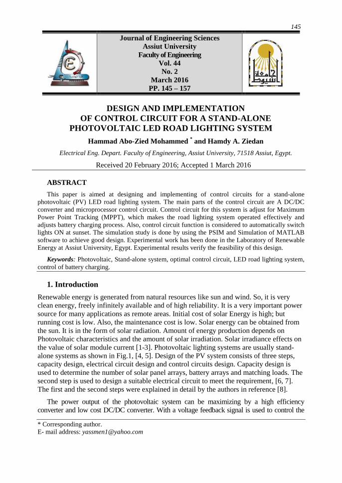
alone systems as shown in Fig.1, [4, 5]. Design of the PV system consists of three steps,
capacity design, electrical circuit design and control circuits design. Capacity design is
used to determine the number of solar panel arrays, battery arrays and matching loads. The
second step is used to design a suitable electrical circuit to meet the requirement, [6, 7].
The first and the second steps were explained in detail by the authors in reference [8].
The power output of the photovoltaic system can be maximizing by a high efficiency
converter and low cost DC/DC converter. With a voltage feedback signal is used to control the
146
JES, Assiut University, Faculty of Engineering, Vol. 44, No. 2, March 2016, pp. 145 – 157
terminal voltage of the photovoltaic system at optimal values in various solar radiation conditions
(MPPT). The operation performance of the photovoltaic lighting system depends on the
controller circuit. LED light consumes very less power. Also, its life time is high. So, in this
work, LED is used as lighting bulb. This paper is aimed at designing and implementing of
optimal control circuit of stand-alone PV lighting system for highways and car parking lighting.
2. Design of control circuits
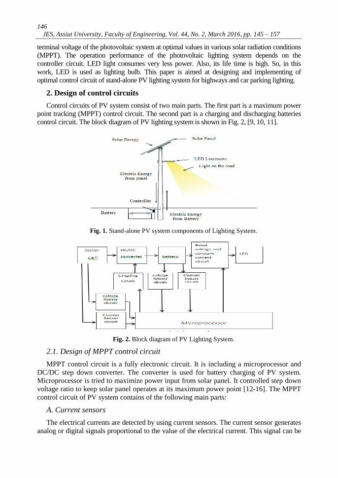
Control circuits of PV system consist of two main parts. The first part is a maximum power
point tracking (MPPT) control circuit. The second part is a charging and discharging batteries
control circuit. The block diagram of PV lighting system is shown in Fig. 2, [9, 10, 11].
Fig. 1. Stand-alone PV system components of Lighting System.
Fig. 2. Block diagram of PV Lighting System.
2.1. Design of MPPT control circuit
MPPT control circuit is a fully electronic circuit. It is including a microprocessor and
DC/DC step down converter. The converter is used for battery charging of PV system.
Microprocessor is tried to maximize power input from solar panel. It controlled step down
voltage ratio to keep solar panel operates at its maximum power point [12-16]. The MPPT
control circuit of PV system contains of the following main parts:
A. Current sensors
The electrical currents are detected by using current sensors. The current sensor generates
analog or digital signals proportional to the value of the electrical current. This signal can be

147
Hammad Abo-Zied Mohammed and Hamdy A. Ziedan, Design and implementation of control ……
used for control purpose as shown in Fig.3. In this work, the generated signal from sensor is
analog voltage. Current is measured by taking a signal from the circuit using a very small
series resistance. Resistance R1 of 0.05 Ω with rated power up to 6 W is used as shown in
Fig.3. a differential amplifier circuit is used as a compensator. The compensator gain is 10.
This compensator is used to avoid power loss and compensate voltage drop in the circuit.
Fig. 3. Current sensor circuit.
B. Voltage sensor
Voltage can be sensed by voltage divider circuit as shown in Fig.4. This is simple linear circuit.
The output voltage (Vout) expressed as a fraction of input voltage (Vin) as expressed by Eqn. 1.
Fig. 4. Voltage sensor circuit.
𝑉𝑜𝑢𝑡 = 𝑅2
𝑅1+ 𝑅2 ∙ 𝑉𝑖𝑛 (1)
𝑉𝑜𝑢𝑡 = 𝐷 ∙ 𝑉𝑖𝑛 (2)
where D is duty cycle.
C. Buck converter
Buck converter is step-down DC to DC converter based on current in inductor. The
inductor current is controlled by switches. MOSFET transistor is used as switch in buck
converter circuit as shown in Fig.5.

148
JES, Assiut University, Faculty of Engineering, Vol. 44, No. 2, March 2016, pp. 145 – 157
Fig. 5. Buck converter.
D. Microprocessor control
The microprocessor control circuit and the DC/DC converter is shown in Fig. 6. [15,
16]. In this circuit, the DC/DC converter is controlled by a microprocessor (PIC16F877A).
The microprocessor is clocked at 20 MHz by the crystal XTAL1. The microprocessor
output of PWM is used to control duty cycle of DC/DC converter which sets its voltage
conversion ratio. The PWM frequency can be sets to 100 KHz by using PIC software.
Also, the PWM duty cycle can be controlled by using PIC software. This control to
optimize solar panels output power [17]. The microprocessor output is used to controlling
the MOSFET driver (2004A). The microprocessor calculates the power generated from the
solar panels through A/D converter as shown in Fig.6.
Fig. 6. The microprocessor control circuit and the DC/DC converter.
149
Hammad Abo-Zied Mohammed and Hamdy A. Ziedan, Design and implementation of control ……
E. Circuit description and operation
The DC/DC converter is a synchronous MOSFET (Q1) with energy storage devices as
shown in Fig.6. In this figure, the storage devices are inductor (L1) and capacitors (C1, C2 and
C10). The inductor value is 33uH and inductor current 11 A for this work. Both high side and
low side MOSFETs are IRFf250 N-fets. The turn on resistance (Rds) is low. So, N-fets were
chosen to reduce resistance losses in DC/DC converter. When low side MOSFET is turning
on, the circulating current will be flow through a fast recovery diode (D2). Electrical noise
which generated by switching of inductor can be reduced by snubber circuit (C7, R3). During
battery charging, diode (D1) is used to turn off the system. The MOSFET transistor (Q1) is
turned off at night. Also, microprocessor will shut off when there is no longer any solar
power to run it. Diode (D1) is used to block reverse current flow. All the above elements of
the DC/DC converter (Q1, L1, C1, C2, C10, C7, R3, D1, D2, Rds) are shown in Fig.6. The MOSFET
gate driver (2004A) drives high and low side MOSFETs using PWM signal from
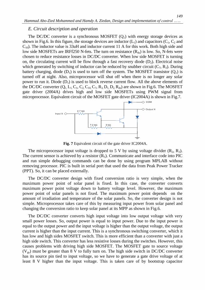
microprocessor. Equivalent circuit of the MOSFET gate driver (IC2004A) is shown in Fig.7.
Fig. 7 Equivalent circuit of the gate driver IC2004A.
The microprocessor input voltage is dropped to 5 V by using voltage divider (R2, R3).
The current sensor is achieved by a resistor (R5). Communicate and interface code into PIC
and run simple debugging commands can be done by using program MPLAB without
removing processor. PIC is built in serial port that used the data from Peak Power Tracker
(PPT). So, it can be placed externally.
The DC/DC converter design with fixed conversion ratio is very simple, when the
maximum power point of solar panel is fixed. In this case, the converter converts
maximum power point voltage down to battery voltage level. However, the maximum
power point of solar panels is not fixed. The maximum power point depends on the
amount of irradiation and temperature of the solar panels. So, the converter design is not
simple. Microprocessor takes care of this by measuring input power from solar panel and
changing the conversion ratio to keep solar panel at its MPP as shown in Fig.6.
The DC/DC converter converts high input voltage into low output voltage with very
small power losses. So, output power is equal to input power. Due to the input power is
equal to the output power and the input voltage is higher than the output voltage, the output
current is higher than the input current. This is a synchronous switching converter, which it
has low and high sides MOSFET switch. This is more efficient than a converter with just a
high side switch. This converter has less resistive losses during the switches. However, this
causes problems with driving high side MOSFET. The MOSFET gate to source voltage
(Vgs) must be greater than 8 V to fully turn on. The high side switch in DC/DC converter
has its source pin tied to input voltage, so we have to generate a gate drive voltage of at
least 8 V higher than the input voltage. This is taken care of by bootstrap capacitor

150
JES, Assiut University, Faculty of Engineering, Vol. 44, No. 2, March 2016, pp. 145 – 157
connected to MOSFET driver (2004A). When low side switch is on, bootstrap capacitor is
charged to the input voltage. Then, when high side switch is on, capacitor adds voltage to
input voltage. So, double input voltage now drives high side switch. High side switch is
turned on full time to connect solar panel to battery directly. Microprocessor,
(PIC16F877A), controls the conversion ratio of DC/DC converter. PIC generates a pulse
width modulation signal at 100 kHz with its internal PWM circuit. Duty cycle of PWM
signal sets ratio of on time for high side versus low side of MOSFET switch. On time ratio
of switches sets the conversion ratio of input to output voltage of DC/DC converter.
The microprocessor sets conversion ratio of DC/DC converter to allow solar panels to
operate at their MPP. Iterative algorithm has been used by microprocessor to maximize input
power of solar panels. Input power from solar panel is calculated by measuring voltage and
current with PIC’s A/D inputs and multiplying internally to get power. Microprocessor
transmits out serial port all values it has measured and calculated (volt, current and power)
once a second to be logged by an external computer. Solar panel input power are measured
and compared with solar panel power at MPP to get the gain or boost of PPT [17].
2.2. Design of control circuit of battery charger
Function of solar charge controller is to regulate power flowing from solar panels to
rechargeable batteries. It consists of one potentiometer for float voltage adjustment, an
equalize function for periodic overcharging, and automatic temperature compensation for
better battery charging over a wide range of temperatures. This circuit is able to handle
reverse polarity connection of both battery and photovoltaic panel [6-13]. Battery Charger
simulation circuit is shown in Fig.8, [13 - 14].
3. Experimental technique
Experimental work has made in Renewable Energy Laboratory, Electrical Engineering
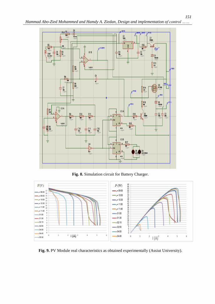
Department, Assiut University, Egypt. Characteristics of PV Module are 83 W with a
maximum open circuit voltage (Voc) of 19.7 V, maximum short circuit current (Isc) of 5.78
A, maximum power voltage (Vrate) of 15 V and maximum power current (Irate) of 5 A.
These characteristics are obtained experimentally during the day time as shown in Fig.9.
Conventional controller simply connects module and battery. Therefore, if module will
operate at 12 V, conventional controller artificially will limit power production to 63 W. In
this work, MPPT system operates module at 15V to extract full power at 83 W.
4. Implementation results and discussion
4.1. Implementation of MPPT control circuit
Fig.10 shows the connection diagram of MPPT circuit which was implemented in the
laboratory. Switching signal with frequency of 100 KHz was generated by PIC as shown in Fig.11.
4.2. Implementation of control circuit of battery charger
Charging circuit is connected between PV module and battery. The connection diagram
of the battery charger is shown in Fig.12.
151
Hammad Abo-Zied Mohammed and Hamdy A. Ziedan, Design and implementation of control ……
Fig. 8. Simulation circuit for Battery Charger.
Fig. 9. PV Module real characteristics as obtained experimentally (Assiut University).

152
JES, Assiut University, Faculty of Engineering, Vol. 44, No. 2, March 2016, pp. 145 – 157
Fig. 10. Connection diagram of MPPT circuit (Assiut University).
Fig. 11. switching signal with 100 KHz frequency (Assiut University).
Fig.12. Connection diagram of battery charger (Assiut University).
The charging circuit consists of the following main parts:
A. Voltage regulator
IC 78l05 was used to generate 5 V-DC. Output voltage signal of IC 78105 is shown in
Fig.13. This voltage is used for all circuit parts which need DC voltage to operate such as
comparator and flip-flop.
153
Hammad Abo-Zied Mohammed and Hamdy A. Ziedan, Design and implementation of control ……
Fig.13 Output voltage signal of IC 78L05 (Assiut University).
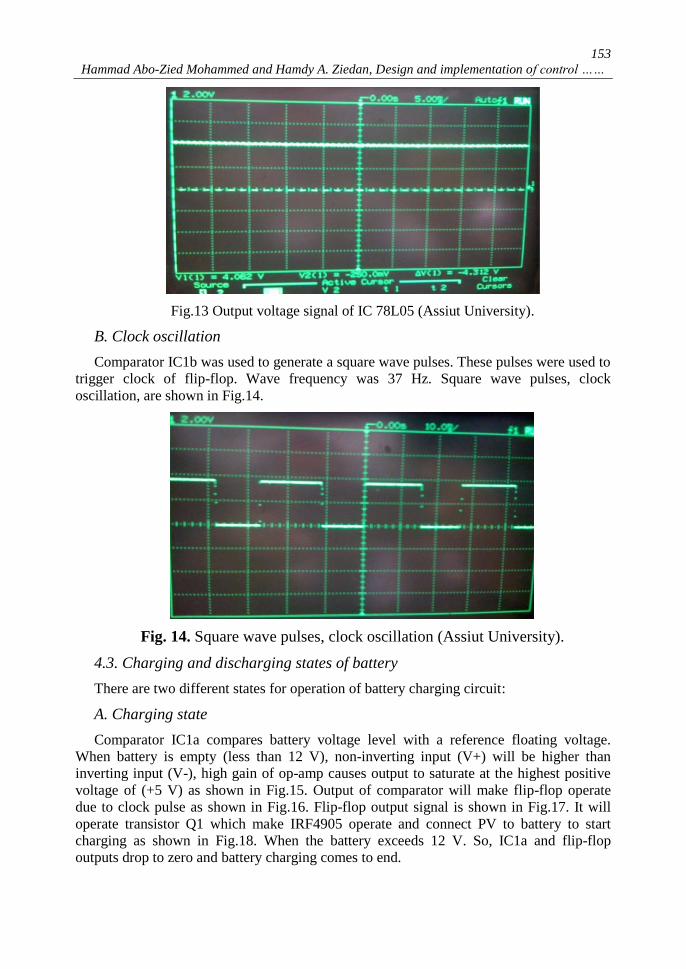
B. Clock oscillation
Comparator IC1b was used to generate a square wave pulses. These pulses were used to
trigger clock of flip-flop. Wave frequency was 37 Hz. Square wave pulses, clock
oscillation, are shown in Fig.14.
Fig. 14. Square wave pulses, clock oscillation (Assiut University).
4.3. Charging and discharging states of battery
There are two different states for operation of battery charging circuit:
A. Charging state
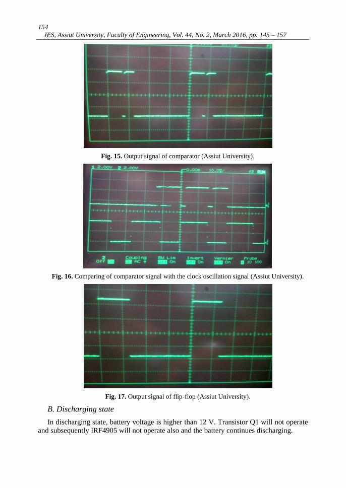
Comparator IC1a compares battery voltage level with a reference floating voltage.
When battery is empty (less than 12 V), non-inverting input (V+) will be higher than
inverting input (V-), high gain of op-amp causes output to saturate at the highest positive
voltage of (+5 V) as shown in Fig.15. Output of comparator will make flip-flop operate
due to clock pulse as shown in Fig.16. Flip-flop output signal is shown in Fig.17. It will
operate transistor Q1 which make IRF4905 operate and connect PV to battery to start
charging as shown in Fig.18. When the battery exceeds 12 V. So, IC1a and flip-flop
outputs drop to zero and battery charging comes to end.
154
JES, Assiut University, Faculty of Engineering, Vol. 44, No. 2, March 2016, pp. 145 – 157
Fig. 15. Output signal of comparator (Assiut University).
Fig. 16. Comparing of comparator signal with the clock oscillation signal (Assiut University).
Fig. 17. Output signal of flip-flop (Assiut University).
B. Discharging state
In discharging state, battery voltage is higher than 12 V. Transistor Q1 will not operate
and subsequently IRF4905 will not operate also and the battery continues discharging.
155
Hammad Abo-Zied Mohammed and Hamdy A. Ziedan, Design and implementation of control ……
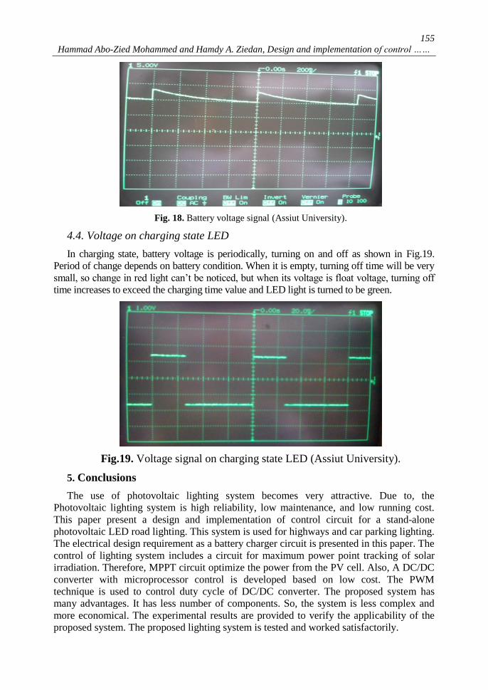
Fig. 18. Battery voltage signal (Assiut University).
4.4. Voltage on charging state LED
In charging state, battery voltage is periodically, turning on and off as shown in Fig.19.
Period of change depends on battery condition. When it is empty, turning off time will be very
small, so change in red light can’t be noticed, but when its voltage is float voltage, turning off
time increases to exceed the charging time value and LED light is turned to be green.
Fig.19. Voltage signal on charging state LED (Assiut University).
5. Conclusions
The use of photovoltaic lighting system becomes very attractive. Due to, the
Photovoltaic lighting system is high reliability, low maintenance, and low running cost.
This paper present a design and implementation of control circuit for a stand-alone
photovoltaic LED road lighting. This system is used for highways and car parking lighting.
The electrical design requirement as a battery charger circuit is presented in this paper. The
control of lighting system includes a circuit for maximum power point tracking of solar
irradiation. Therefore, MPPT circuit optimize the power from the PV cell. Also, A DC/DC
converter with microprocessor control is developed based on low cost. The PWM
technique is used to control duty cycle of DC/DC converter. The proposed system has
many advantages. It has less number of components. So, the system is less complex and
more economical. The experimental results are provided to verify the applicability of the
proposed system. The proposed lighting system is tested and worked satisfactorily.
156
JES, Assiut University, Faculty of Engineering, Vol. 44, No. 2, March 2016, pp. 145 – 157
6. Acknowledgment
The authors would like to thank Prof. Mazen Abdel-Salam of Assiut University, Egypt for his
interest and help in this research work.
REFERENCES
[1] B Parida, S Iniyanb, R. Goicc, “A review of solar photovoltaic technologies”, Renewable
Sustainable Energy Rev, pp. 1625–1636, 15/3/2011.
[2] Khaled Bataineh, Doraid Dalalah, “Optimal Configuration for Design of Stand-Alone PV
System”, Smart Grid and Renewable Energy, scientific research, PP. 139-147, 3, 2012.
[3] M. Villalva, J. Gazoli, and E. Filho, “Comprehensive approach to modeling and simulation of
photovoltaic arrays”, IEEE Trans. on Power Electronics, Volume 24, pp. 1198-1208. 2009.
[4] S. Harrington and T. Hund, “Photovoltaic lighting system performance”, 25th
IEEE
Photovoltaic Specialists Conference, pp. 1307-1310, Washington DC, USA, 1996.
[5] S. Hiranvardom, “A Comparative analysis of photovoltaic street lighting systems installed
in Thailand”, 3rd
IEEE World Conference on Photovoltaic Energy Conversion, pp. 2478-
2481, Osaka, Japan, May 2003.
[6] D. Srivatsa, B. Preethi, R. Parinitha, G. Sumana and A. Kumar, “Smart Street Lights”,
TIIEC, Texas Instruments Conference on India Educators, India, pp.103-106, 2013.
[7] W. Yue, S. Changhong, Z. Xianghong and Y. Wei, “Design of new intelligent street light
control system”, 8th
IEEE International Conference on Control and Automation, China, pp.
1423-1427, 2010.
[8] H. Abo-Zied Mohammed and M. Bedda. “Stand-alone photovoltaic lighting system for
highway”, workshop on Towards a Better Environmental Future, Shaqra University, Saudi
Arabia, PP. 20-25, 2014.
[9] N. Mutoh, M. Ohno and T. A. Inoue, “Method for MPPT control while searching for
parameters corresponding to weather conditions for PV generation systems,” IEEE Tran.
on Industrial Electronics, Volume 53, No. 4, pp. 1055-1065, 2006.
[10] A. K. Abdelsalam, A. M. Massoud, S. Ahmed and P. N. Enjeti, “High-Performance
adaptive perturb and observe MPPT technique for photovoltaic-based Micro grids,” IEEE
Trans. on Power Electronics, Volume 26, No. 4, pp. 1010-1021, 2011.
[11] Filippo Spertino, Jawad Ahmad, Alessandro Ciocia, Paolo Di Leo, Ali F. Murtaza,
Marcello Chiaberge, “Capacitor charging method for I–V curve tracer and MPPT in
photovoltaic systems” Solar Energy, Volume 119, Pages 461-473, September 2015.
[12] Boualem Bendib, Hocine Belmili, Fateh Krim," A survey of the most used MPPT methods:
Conventional and advanced algorithms applied for photovoltaic systems”, Renewable and
Sustainable Energy Reviews, Volume 45, Pages 637-648, May 2015
[13] F. License, "Remote-control system of high efficiency and intelligent street lighting using a
Zigbee network of devices and sensors," IEEE Trans. on Power Delivery, Volume 28, Issue
1, pp. 21-28, 2013.
[14] S.Sivagamasundari, P.Melba Mary, V.K.Velvizhi, ” Maximum Power Point Tracking For
Photovoltaic System by Perturb and Observe Method Using Buck Boost Converter”,
International Journal of Advanced Research in Electrical, Electronics and Instrumentation
Engineering Vol. 2, Issue 6, 24-33, June 2013.
[15] J. Gu, F. Qing, L. Hua, X. Guo, L. Lv and Y. Yuan, “The design of one controlling circuit
for solar lighting system”, IEEE International Conference Information Science and
Technology, pp. 1208 – 1211, China, 26-28 Mar 2011.
[16] C. Bhuvaneswari, R. Rajeswari and C. Kalaiarasan, “Analysis of solar energy based street light
with auto tracking system”, IJAREEIE, International Journal of Advanced Research in Electrical,
Electronics and Instrumentation Engineering, Vol. 2, Issue 7, pp. 3422-3428, July 2013.
[17] Hegazy Rezk, Ali M. Eltamaly, “A comprehensive comparison of different MPPT techniques
for photovoltaic systems”, Solar Energy, Volume 112, Pages 1-11, February 2015.

157
Hammad Abo-Zied Mohammed and Hamdy A. Ziedan, Design and implementation of control ……
تصميم وتنفيد دائرة تحكم لنظام تحويل الطاقة الشمسية الى طاقة ضوئية
غير متصل بالشبكة الكهربائية النارة طريق باستخدام الباعث الضوئى
الملخص العربى:
التحكم لنظام تحويل الطاقة الشمسية الى طاقة ضوئية يهدف هدا البحث لتصميم وتنفيد دوائر
(photovoltaic( غير متصل بالشبكة الكهربائية النارة طريق باستخدام الباعث الضوئى )LED الباعث .)
الضوئى يتم استخدامه فى هده النظام كمصدر للضوء. االجزاء الرئيسية من دائرة التحكم هى محول التيار
ودائرة تحكم المعالج المصغر. يتم ضبط دائرة التحكم لكى يعطى نظام DC/DC converter) (المستمر
(. مما يجعل نظام اضاءة الطرق يعمل بكفاءة, ويتم ضبط MPPTاالضاءة اكبر قيمة من القدرة الكهربائية )
راسة عملية شحن البطارية. وايضا من وظائف دائرة التحكم التوصيل والفصل اليا لنظام االضاءة. تم د
لتحقيق التصميم الجيد. تمت الدراسة MATLABوبرنامج PSIMالمحاكاة النظرية باستخدام برنامج
العملية لنظام االضاءة بالطاقة الشمسية فى معمل الطاقة المتجددة فى جامعة اسيوط بمصر. تحقق النتائج
العملية جدوى هدا التصميم.


![DC-DC Converter with Coupled Inductor and Multiplier Cells ... · gain is also improved by using a parallel input output series boost converter [13]. This DC-DC Converter makes use](https://img.pdfslide.us/doc/110x75/5f0b56627e708231d43004bb/dc-dc-converter-with-coupled-inductor-and-multiplier-cells-gain-is-also-improved.jpg)