Embed Size (px)
Citation preview

Design and Implementation of an
Automatic Conveyor Sorting
System
ENG 615 Engineering Masters Project
Author: Oseikhuemen E. Isiramen
Project supervisor: Associate Professor Graeme Cole
JUNE, 2018

1
DECLARATION
I, Oseikhuemen Eromosele Isiramen, hereby declare that I carried out the work reported in this
report in the School of Engineering and Information Technology, Murdoch University, under the
supervision of Associate Professor Graeme Cole. I declare that to the best of my knowledge, no part
of this report has been submitted here or elsewhere in previous application for award of a degree.
Except where stated otherwise by reference or acknowledgement, the work presented in this report
is completely my own.
Oseikhuemen Eromosele Isiramen
8/5/2018

2
ACKNOWLEDGEMENT
I would like to express my sincere gratitude to all those that helped me in one way or another
throughout the course of my study. I really appreciate the advice and guidance I got from my project
supervisor Associate Professor Graeme Cole who always encouraged me to go forward with my
ideas and do the best I can. I also appreciate Will Stirling, Iafeta Laava, Mark Burt, and most
especially Graham Malzer for the assistance and advice they gave me during this project without
which, this project would not have gone this far.
I also want to thank my friends Vaishali Sharma, and Adam Portillo who helped me in dealing with
some personal challenges I faced during the course of this project. I really appreciate the advice and
assistance I got from them. They were always willing to go the extra mile for me and for this, I am
forever grateful.
Special thanks to my beautiful, and loving Fiancée Adebola Racheal Adesida for always finding a way
to make me happy even in terrible times. Above all, I appreciate my heavenly father GOD almighty
for his continuous guidance and protection all through my studies. His love and blessings have
always been abundant. I also appreciate my brother in‐law Vincent Ugbeni, my sister Osezele
Ugbeni, my brothers Joseph Isiramen and Ehinomen Isiramen for letting me know they always care
about me.
Without the best parents in the world, I would never have been able to complete this program. My
wonderful parents Dr. and Prof. Isiramen made sure I never lacked anything and struggled so hard to
make it possible for me to study in Murdoch University. I will never forget how hard they have
struggled to give me the best they possibly can and for that, I am eternally grateful.

3
ABSTRACT
One of the challenges of automation engineers is coming up with the best possible way to automate
a process. There are many sensors, controllers, remote I/O devices, and actuators in the world today
that makes it difficult for one to decide on which particular device to use for a particular application.
Prior knowledge of some of the key components required for automation is necessary to help with
the selection process. This design and implementation of an automatic conveyor system project was
designed to be used as a teaching tool at Murdoch University to expose students to different
components used in automation and how these components can be put together to achieve a
required goal. This project is concerned with designing, developing, and commission of a conveyor
colour sorting and scattering system. There are six sections in this report.
The first section of this report introduces the project. It talks about why this project has been
undertaken, the aim, and objectives of the project. For better execution of the project, the project
was divided broadly into four different stages with each stage having set objectives. These stages
and their objectives are also discussed in this part of the report. Following on from the first section,
the second section talks about the background of automation. A brief history of automation which
dates as far back as 1769, advantages and disadvantages of automation, key components required
for automation are discussed in this section. The last part of section two talks about the previous
work that was carried out by other students on the conveyor system.
Details about the system design, materials selection, and construction of the system are in sections
three and four of this report. Effort was put into trying to make use of different kinds of components
so that students who study the system can develop an understanding of various kinds of automation
components. Incorporating the various components selected as well as developing the computer
program to carry out the required task of the system is presented in section four.
The system was tested twice. Once with coloured wooden boxes and the other with polycarbonate
boxes fitted with coloured acrylics. The first test was unsuccessful while the second was a success
which shows the importance of proper material selection. The system was able to transport boxes
across four conveyor belts and sort them according to their colours. The last two sections of this
report discuss the various challenges encountered during the project execution as well as possible
advancements that can be done on the system.
It was discovered that the knowledge of the different components used in automation and how they
can be used can go a long way in the achievement of a required goal especially as an effective tool
for teaching.

4
CONTENTS
DECLARATION ......................................................................................................................................... 1
ACKNOWLEDGEMENT ............................................................................................................................. 2
ABSTRACT ................................................................................................................................................ 3
CONTENTS ............................................................................................................................................... 4
LIST OF FIGURES ...................................................................................................................................... 6
LIST OF TABLES ........................................................................................................................................ 6
SECTION 1: Introduction to the Project .................................................................................................. 9
1.1 INTRODUCTION ....................................................................................................................... 9
1.2 PROJECT AIM ........................................................................................................................... 9
1.3 PROJECT OBJECTIVES/STAGES ................................................................................................ 9
1.3.1 STAGE 1: RESEARCH AND FAMILIARISATION STAGE ..................................................... 10
1.3.2 STAGE2: DESIGN STAGE ................................................................................................ 10
1.3.3 STAGE 3: IMPLEMENTATION STAGE ............................................................................. 10
1.3.4 STAGE 4: COMMISSIONING AND DOCUMENTATION STAGE ........................................ 10
SECTION 2: Automation and Project Background ................................................................................. 11
2.0 AUTOMATION BACKGROUND ............................................................................................... 11
2.0.1 BRIEF HISTORY OF AUTOMATION ................................................................................. 11
2.0.2 ADVANTAGES AND DISADVANTAGES OF AUTOMATION .............................................. 12
2.0.2 KEY COMPONENTS REQUIRED FOR AUTOMATION ...................................................... 12
2.1 PROJECT BACKGROUND ........................................................................................................ 18
2.2 PROJECT RISK AND CONSTRAINTS ........................................................................................ 20
SECTION 3: Design ........................................................................................................................... 21
3.0 BOX SENSORS ........................................................................................................................ 22
3.0.1 VTE18‐4P2740 PHOTOELECTRIC PROXIMITY SENSOR .................................................. 23
3.0.2 VTE18‐4N4240V PHOTOELECTRIC PROXIMITY SENSOR ................................................ 24
3.0.3 WT18‐2P2112 PHOTOELECTRIC PROXIMITY SENSOR ................................................... 24
3.0.4 WL11‐2N2430 PHOTOELECTRIC RETRO‐REFLECTIVE SENSOR ...................................... 25
3.1 COLOUR SENSORS ................................................................................................................. 26
3.2 TRANSPORT PACKAGE ........................................................................................................... 27
3.3 PNEUMATIC CYLINDERS ........................................................................................................ 28
3.4 DIRECTIONAL CONTROL VALVES ........................................................................................... 29
3.5 VACUUM TECHNOLOGY ........................................................................................................ 30
3.5.1 VACUUM PUMP ............................................................................................................ 30
3.5.2 GRIP VALVE ................................................................................................................... 31

5
3.5.3 SUCTION CUP ................................................................................................................ 31
3.6 CONTROLLER AND COMMUNICATION DEVICE ..................................................................... 32
3.7 OTHER COMPONENTS ........................................................................................................... 33
SECTION 4: Implementation ................................................................................................................. 35
4.0 I/O MODULES AND COLOUR SENSOR CONFIGURATION ...................................................... 35
4.1 TRANSFER PLATFORM 1, 2, AND 3 ........................................................................................ 37
4.2 RETURN MECHANISM ........................................................................................................... 42
4.2.1 TRANSFER PLATFORM 4 ................................................................................................ 42
4.2.2 ROLLER CONVEYOR ....................................................................................................... 45
4.2.3 PICK AND PLACE SYSTEM .............................................................................................. 45
4.3 CONVEYOR WIRING .............................................................................................................. 49
4.4 CONTROL UNIT AND I/O COMMUNICATION ........................................................................ 50
4.5 DISTRIBUTION BOARDS AND EMERGENCY SHUT DOWN ..................................................... 52
4.5.1 SAFETY HAZARDS .......................................................................................................... 54
4.6 SOFTWARE DEVELOPMENT ................................................................................................... 54
4.6.1 PROJECT VIEW POINT .................................................................................................... 54
4.6.2 PROGRAM DEVELOPMENT............................................................................................ 55
4.7 TESTING ................................................................................................................................. 58
SECTION 5: Challenges encountered and future works ........................................................................ 59
5.0 CHALLENGES ENCOUNTERED ................................................................................................ 59
5.1 FUTURE WORKS .................................................................................................................... 60
SECTION 6: Conclusion .......................................................................................................................... 62
BIBLIOGRAPHY ...................................................................................................................................... 63
APPENDIX A: Conveyor Three‐phase wiring ......................................................................................... 67
APPENDIX B: DB1 and DB2 wiring ......................................................................................................... 68
APPENDIX C: Sub state machine diagrams ........................................................................................... 69
APPENDIX D: Start‐up guide .................................................................................................................. 72
APPENDIX E: Video Link ........................................................................................................................ 75

6
LIST OF FIGURES
Figure 1: Conveyor marshalling cabinet wiring (Brain, Pezzaniti, Portillo, & Cason, 2017) .................. 19
Figure 2: Conveyor system with various components identified (Slipper, Boland, Jian, & Barrett,
2017) ..................................................................................................................................................... 19
Figure 3: Schematic diagram ................................................................................................................. 21
Figure 4: Return mechanism schematic diagram ................................................................................. 22
Figure 5: VTE18‐4P2740 photoelectric proximity sensor ..................................................................... 23
Figure 6: VTE18‐4N4240V photoelectric proximity sensor ................................................................... 24
Figure 7: WT18‐2P112 photoelectric proximity sensor ........................................................................ 25
Figure 8: WL11‐2N2430 retro‐reflective sensor ................................................................................... 25
Figure 9: CSM‐WP117A2P colour sensor .............................................................................................. 26
Figure 10: Initial box made for testing .................................................................................................. 27
Figure 11: Box supplied by a vendor for final implementation ............................................................ 27
Figure 12: 5/3 solenoid valve ................................................................................................................ 30
Figure 13: 12V‐DC Vacuum pump ......................................................................................................... 30
Figure 14: 12VDC Solenoid valve used for gripping .............................................................................. 31
Figure 15: Suction cup ........................................................................................................................... 32
Figure 16: ADAM 6052 I/O module with specifications (ADVANTECH Co. Ltd, n.d.) ............................ 32
Figure 17: ADAM 6250 with specifications (ADVANTECH Co. Ltd, n.d.) ............................................... 33
Figure 18: ADAM 6052 module Input setting ....................................................................................... 35
Figure 19: ADAM 6250 module input setting ....................................................................................... 35
Figure 20: Network topology ................................................................................................................ 37
Figure 21: Base and top view of platform under construction ............................................................. 38
Figure 22: Base platform support made using strut channels .............................................................. 38
Figure 23: Top view of the completed platform ................................................................................... 39
Figure 24: Side view of completed platform ......................................................................................... 39
Figure 25: Transfer platform 1 wiring diagram ..................................................................................... 40
Figure 26: Transfer platform 2 wiring diagram ..................................................................................... 40
Figure 27: Transfer platform 3 wiring diagram ..................................................................................... 41
Figure 28: Front view of transfer platform 4 ........................................................................................ 43
Figure 29: Back and side view of transfer platform 4 ........................................................................... 43
Figure 30: Transfer platform 4 wiring diagram ..................................................................................... 44
Figure 31: Roller conveyor .................................................................................................................... 45
Figure 32: Top view of the pick and place device ................................................................................. 46
Figure 33: Front view of the pick and place mechanism ...................................................................... 46
Figure 34: Side platform of the pick and place system ......................................................................... 47
Figure 35: Sensors used for the pick and place system ........................................................................ 47
Figure 36: Pick and place system wiring diagram ................................................................................. 48
Figure 37: I/O module installed on the conveyor system ..................................................................... 49
Figure 38: conveyor I/O module wiring diagram .................................................................................. 50
Figure 39: Back view of the control unit ............................................................................................... 51
Figure 40: Front view of the control unit .............................................................................................. 51
Figure 41: Control unit wiring diagram ................................................................................................. 52
Figure 42: Distribution boards diagram ................................................................................................ 53
Figure 43: 24V E‐stop circuit ................................................................................................................. 54
Figure 44: Aerial shot of assembled system and view point of the sub systems ................................. 55
Figure 45: Program block diagram ........................................................................................................ 55

7
Figure 46: Program front panel ............................................................................................................. 56
Figure 47: Flow chart for colour sorting explanation ........................................................................... 57
Figure 48: Conveyor three‐phase wiring ............................................................................................... 67
Figure 49: DB1 wiring diagram .............................................................................................................. 68
Figure 50: DB2 wiring diagram .............................................................................................................. 68
Figure 51: Initialise sub state machine diagram ................................................................................... 69
Figure 52: Simple transfer sub state machine diagram ........................................................................ 69
Figure 53: Sorting sub state machine diagram ..................................................................................... 70
Figure 54: Scatter sub state machine diagram ..................................................................................... 70

8
LIST OF TABLES
Table 1: Engineering 447/617 students to previously work on the conveyor belt ............................... 18
Table 2: VTE18‐4P2740 photoelectric proximity sensor specification (SICK Sensor Intelligence, 2017)
.............................................................................................................................................................. 23
Table 3: VTE18‐4N4240V photoelectric proximity sensor specification (SICK Sensor Intelligence,
2017) ..................................................................................................................................................... 24
Table 4: WT18‐2P112 photoelectric proximity sensor specification (SICK Sensor Intelligence, 2017) 25
Table 5: WL11‐2N2430 retro‐reflective sensor (SICK Sensor intelligence, 2017) ................................. 26
Table 6: CSM‐WP117A2P colour sensor specification (SICK sensor intelligence, 2017)....................... 27
Table 7: IP addresses and platform attached ....................................................................................... 36

9
SECTION 1: Introduction to the Project
1.1 INTRODUCTION
Automation is the technique of making an apparatus, a system or a process operate automatically
thereby eliminating the need for human labour (Automation, n.d.). It has become common practice
for most industries in the world today to incorporate automation into their production processes
because it's cost‐effective, efficient, and fast. Due to the advancement of automation, it has become
paramount to investigate different ways in which a process can be automated.
The decision on how a system or process will be automated depends on the type of system. For
example: In the aviation industry, it is required to transport passenger's luggage from the check‐in
counter to the airplane. It would be really difficult and time‐consuming if the check‐in steward had
to carry every passenger's luggage individually to the point where it would be transferred to the
airplane. To make this process more efficient, and less stressful, a conveyor belt can be used to carry
out this task thereby eliminating the need for human labour. The system can also be developed to
include sensors which can read the bag tags and automatically sort them according to their final
destination.
In 2017, Murdoch University Engineering Department acquired four conveyor belts from Perth Print
where they were used as part of the production process for printing newspapers (Slipper, Boland,
Jian, & Barrett, 2017). The idea was to use these conveyor belts to set up a system which could be
used for demonstration and teaching purposes in Industrial Computer System Engineering. This
project is concerned with the design, construction, and commissioning of an automatic conveyor
sorting system in the Pilot Plant area located in the Engineering and Energy building at Murdoch
University South Street Campus.
1.2 PROJECT AIM
The aim of this project is to design a system that moves packages around four conveyor belts in a
continuous loop and sort the packages according to their colours. For the system to continue
operating without having to stop and start the system once the sorting has been completed, the
system will have to scatter (i.e. randomly rearrange) the packages automatically and sort them
again. This means that once the start button is activated, the system will start to sort and scatter the
packages autonomously like the way a Rubik's cube is solved and then rearranged so that it can be
solved again.
This system will be used as both a teaching and demonstration tool for future students and visitors.
The system will make use of 4 conveyor belts, pneumatic cylinders, grippers, suction cups, transfer
platforms, directional control valves, light sensors, coloured sensors among others. A program will
be developed in LabVIEW to control the operation of the various components to achieve the
required goal. This project will demonstrate to some extent the robust nature of automation.
1.3 PROJECT OBJECTIVES/STAGES
For better execution of this project, the project was broadly divided into four stages with each stage
having its unique set of objectives. These four stages and objectives are discussed below.

10
1.3.1 STAGE 1: RESEARCH AND FAMILIARISATION STAGE
This stage of the project has to do with understanding what the project is all about. That is, to firstly
gain enough knowledge about the project in order to make adequate plans on how to execute the
project and determine what will be required to do so. The objectives of this stage are listed below.
1. Study previous work done on the conveyor system
2. Research various ways conveyor systems are used in industries
3. Discuss with the project supervisor regarding his intentions for the conveyor system
4. Verify correct functionality of each individual conveyor belt
1.3.2 STAGE2: DESIGN STAGE
This stage has to do with developing a design of how the different components will be put together
to achieve the goal of this project. The objectives associated with this stage are listed below.
1. Determine the amount of space needed in the Pilot Plant to set up the conveyor system.
2. Research on the various apparatus that will be needed to carry out this project.
3. Decide on which control approach to follow.
4. Decide on which controllers to use.
5. Draw up a schematic diagram showing the arrangement of the conveyor belts in the pilot
plant.
1.3.3 STAGE 3: CONSTRUCTION STAGE
In this stage of the project, the actual construction of the sorting system will be done. For this
implementation to be successful, the objectives listed below are required.
1. Work with the Murdoch University technical staffs (Mark, Graham, Iafeta, and Will) to build
the required platforms and attach the necessary equipment to the platforms.
2. Hold further meetings with the project supervisor to determine what can be purchased for
the project.
3. Connect the electrical and air supplies to the appropriate equipment.
4. Install controllers or I/O modules on each conveyor and sub systems.
5. Develop a complex program to achieve the required goal.
1.3.4 STAGE 4: COMMISSIONING AND DOCUMENTATION STAGE
After completing stage 3, the entire system will be commissioned and tested. The objectives of this
stage include the following:
1. Test the code developed in stage 3 in the presence of the project supervisor.
2. Make necessary adjustment to the code.
3. Final commissioning of the project which includes developing a start‐up guide for anyone
who wants to operate the system.
4. Documentation.

11
SECTION 2: Automation and Project Background
2.0 AUTOMATION BACKGROUND
2.0.1 BRIEF HISTORY OF AUTOMATION
The efficiency of industrial processes today is because of the diligence of individuals committed to
improving automated systems. In the 50's and 60's, technicians and engineers had to do physically
challenging, and time‐consuming work to complete an industrial process. For this reason, it became
necessary to develop devices which would make industrial processes more efficient and this led to
the development of modern‐day controllers (Segovia & Theorin, 2012).
Any mention of automation technology in recent times makes people think about industrial robots
and computer controllers. However, automation technology began in industries in 1769 with the
utilisation of the steam engine by James Watt. Steam engines were used to drive several machine
tools and drain water from mines. Electromagnetism was discovered in 1820 by Oersted, a Danish
physicist, and in 1834, Thomas Davenport developed the first direct current motor with a
commutator. The electric motor went on to replace the steam engine as a driving component after
Werner von Siemens invented the dynamo which was a simpler way of generating electrical current
in large quantities (Ebel, Idler, Prede, & Scholz, 2008).
Henry Ford in 1913 developed the first production line for the Model T. This resulted in increased
productivity as the time required to produce one car reduced from seven hundred and fifty to
ninety‐three hours. This meant that eight cars could be produced in the same time it took to
produce one car. The increased productivity made it possible for the price of a Model T car to drop
thereby making it a consumer item for wider sections of the population. Henry Ford's assembly line
was based on Frederick Winslow Taylor's division of labour work where complex production
processes can be divided into several smaller parts that even non‐skilled workers could perform. An
electromagnetic switch was invented by Joseph Henry in 1837. The electromagnetic switches were
called relays and were initially used as signal amplifiers in Morse stations. Later, they were used in
building hard‐wired programmed controllers (Ebel, Idler, Prede, & Scholz, 2008).
The invention of relays made it possible to automatically carry out complex tasks. However, these
relays were expensive, difficult to wire, difficult to configure, and difficult to troubleshoot.
Configuring and troubleshooting the system took a lot of time and was very challenging. Also, once
the relay system was finally configured and operational, making changes to the system was difficult.
These limitations led to the development of programmable logic controllers (PLCs). Mr. Dick Morley
notes that the modern PLC was born on New Year's Day, 1998. The first PLC delivered was called
Modicon which means MOdular Digital CONtroller. A PLC program can simply be adjusted to make
changes to an industrial process without having to physically re‐wire several relays (Hayden, Assante
, & Conway, 2014).
Industrial robots became mainstream in modern industrial production in 1970, and their importance
continues to grow. There are over one hundred thousand robots in Germany alone (Ebel, Idler,
Prede, & Scholz, 2008). This project falls under instrumentation and control because electronic
devices will be used to monitor and operate equipment used for different applications.

12
2.0.2 ADVANTAGES AND DISADVANTAGES OF AUTOMATION
With the vast application of automation technology, one can be tempted to say there are no
downsides of automation but this is not the case. Nonetheless, the advantages usually outweigh the
disadvantages. Therefore, it is necessary to review every case carefully to make sure the right
decision is made. Some of the benefits and drawbacks of automation are listed below (Granta,
2017).
ADVANTAGES
1. Increases productivity
2. Increase in profit
3. Better working environment
4. Improves product quality
5. Production of uniform components
6. Improves the economy
7. Consistency (Gupta, Arora, & Wescott, 2017)
DISADVANTAGES
1. Cost of automating a process can be very expensive
2. Requires a lot of skilled workers to implement
3. Might not be flexible
4. Unemployment rates increase because machines are being used to perform tasks that
humans would normally do (Gupta, Arora, & Wescott, 2017).
2.0.2 KEY COMPONENTS REQUIRED FOR AUTOMATION
Human beings can make decisions based on what they can see, feel, touch, and understand. With
the human eye, we can see what colour a box is or what tag is on a particular luggage and using
manpower, carry the box or luggage to their required position. This is what automation aims to
eliminate by developing machines which can carry out such tasks. Discussed below are the key
components required to make a system automated.
2.0.2.0 SENSORS
Sensors are devices used for collecting and forwarding information from ‘’the real world’’ to
processing devices. Sensors are necessary because instead of having a human being determine the
colour of a box, a colour sensor can perform the same function. A sensor can either send digital or
analogue signals depending on the type of sensor and application. An analogue sensor produces an
analogue continuous signal such as an electrical voltage while digital sensors have only certain
values like 1 or 0 (Salvendy, 2002). The desirable characteristics of sensors are listed below.
Accuracy
Precision
Wide operation range
High response speed
High reliability
Low cost

13
Minimum drift
Ease of calibration (Salvendy, 2002).
Sensors are used in diverse ways, and thus, it is important to classify them. Listed below are the
various classifications of sensors.
1. Classification based on operating principle: this classification is about how sensors operate
(optical, inductive, magnetic, and so on.)
2. Classification based on what they measure: they can be used to measure distance, pressure,
the presence of objects, and so on.
3. Classification based on output signal: digital, analogue.
Digital sensors are preferred to analogue sensors in automation technology because digital outputs
are less affected by interference compared to analogue outputs (Ebel, Idler, Prede, & Scholz, 2008).
This project makes use of optical sensors, magnetic sensors, and limit switches.
2.0.2.0.1 MAGNETIC SENSORS
Magnetic sensors are used in home appliances, cars, and industries to name a few. A major
advantage of magnetic sensors is that they are resistant to vibrations, dirt, and interference (Czech
Tecnical University, 2003). A magnetic reed switch which is used in this project is an example of a
magnetic sensor.
Magnetic reed switches act as proximity sensors and are activated by the action of a magnet. The
inside of the switch has two blades in a glass tube filled with protective gas. When a magnet comes
close to the reed switch, it causes the two blades to come together thereby closing the contact and
allowing the flow of current. Reed switches can be designed to have either normally closed (NC)
contact or normally open contact (NO) (Ebel, Idler, Prede, & Scholz, 2008).
2.0.2.0.2 OPTICAL SENSORS
Optical sensors are measuring devices in which a measured quantity is converted to an optical and
subsequently, an electrical signal by means of an optoelectronic transducer. Optical sensors belong
to the class of contactless methods of measurement, eliminating backward influence of a measuring
device on an object of measurement (Czech Tecnical University, 2003).
Optical sensors have an emitter and a receiver. The emitter emits a light beam and depending on the
type of optical sensor, the light beam will either be blocked from or reflected to the receiver by an
object. Hence, the output of the sensor will be switched once an object is present (Jack, 2007). There
are three types of optical sensors namely: Retro‐reflective, Through‐beam, and Diffuse optical
sensors. Another application of optical sensors is for the detection of colours (Czech Tecnical
University, 2003).
RETRO‐REFLECTIVE SENSOR
A retro‐reflective sensor consists of a transmitter, a receiver, and a reflector. The transmitter and
receiver are encompassed in a single housing. A reflector is placed on the line of sight of the emitter
which reflects the emitted light to the receiver. Once an object or human obstructs the emitted light
to the reflector, the receiver will no longer get any reflected light, and the sensor output will be
triggered to indicate the presence of an object or human (PERRERL+FUCHS, 2009).

14
THROUGH‐BEAM SENSOR
A through‐beam sensor makes use of an emitter and a receiver which are in separate housings.
There is no light reflected. The emitted light goes straight to the receiver, and object detection is
achieved when the emitted light to the receiver is interrupted (PERRERL+FUCHS, 2009).
DIFFUSE SENSOR
A Diffuse sensor has the same working principle as the retro‐reflective sensor. However, the
reflector is the detected object. The emitted light hits the object and is reflected back to the
receiver. Diffuse sensors have a shorter sensing range than the retro‐reflective sensor because of the
diffuse nature of the reflected light (PERRERL+FUCHS, 2009).
COLOUR SENSORS
Colour sensors are widely used in industries. They are used in assembly lines for sorting products
according to colours. Their main objectives are to check the quality of products, facilitate sorting,
packaging, and monitor waste products. Optical colour sensors work by shining a light on an object,
and the reflected light is used to determine the colour of the object. For example, a white light
focused onto a red surface is reflected as red (Assaad, Yohannes, Bermak, Ginhac, & Fabrice , 2014).
Colour sensors are often taught a colour, and when that colour is detected, the output of the sensor
is switched (Lamb, 2013). Retro‐reflective, and diffuse sensors were used for this project.
FEATURES OF OPTICAL SENSORS
1. Long distance sensing
2. Quick response time
3. High resolution
4. Does not need to come in contact with an object to detect it
5. Can be used for colour identification (OMRON, n.d.).
2.0.2.0.3 LIMIT SWITCHES
‘’A limit switch is an electromechanical device that consists of an actuator mechanically linked to a
set of contacts and is widely used for control of machines, as safety interlocks, or to count objects
crossing a point‘’ (Chen , Tan, & Fang, 2014, p. 1).
Limit switches are similar to any other kind of switch as they close or open contacts when they come
in contact with an object. The main difference between a normal switch and a limit switch is its
rugged nature. Limit switches have specialised casings to make it possible for the switch to operate
under harsh environmental conditions. Plunger, Hinge lever, Roller lever are examples of the drive
mechanisms of limit switches (OMRON, n.d.). More details will be given about the limit switches
used in this project in the design section of this report.
2.0.2.1 ACTUATORS
Actuators are another key component required for automation. While sensors are needed to
replicate human abilities like sight, hearing, and feeling, actuators are needed to replicate
manpower. Actuators are used for generating force, motion, heat, etc. Therefore, it is of utmost
importance to select the proper actuator for a particular system (de SILVA, 2007).

15
Actuators are generally classified as electrical, electromechanical, electromagnetic, hydraulic or
pneumatic actuators. ‘'Some typical examples of the coupling mechanism used in combination with
actuators are rack and pinion, gear drive, belt drive, lead screw and nut, piston and linkages''
(Anjanappa, Datta, & Song, 2002). Different classes of actuators listed above except hydraulic
actuators have been utilised for this project.
2.0.2.1.1 ELECTRICAL ACTUATORS
Electrical actuators are typically activated by electrical signals. Most on/off control operations are
performed by electrical switches such as relays, transistors, contactors, etc. These switches accept
low energy level signals and switch on/off higher energy level devices. For example, a 24VDC
contactor can be used to switch on/off a 415VAC motor (Anjanappa, Datta, & Song, 2002). The
conveyor belts used for this project are activated by 24VAC contactors which close a three‐phase
contact that supply power to the three‐phase motor controlling the movement of the conveyor belt.
2.0.2.1.2 ELECTROMECHANICAL ACTUATORS
Electrical and mechanical are the two words that make up electromechanical. Electromechanical
systems convert electrical energy into mechanical motion and sometimes convert mechanical
motion to electrical energy. A common example of an electromechanical actuator is an electric
motor. An electric motor in combination with a gear box can be used to produce slower rotary
actuation just the way it is used in most conveyor belt technologies (Cave, 1995). Electric motors can
generally be classified as DC motors, AC motors, and stepper motors.
Four conveyor belts were used as part of this project. More details about the conveyor belts are
discussed in section 2.1 of this report.
2.0.2.1.3 ELECTROMAGNETIC ACTUATORS
An electromagnetic sensor uses electric energy to create a magnetic field which provides the
necessary energy for actuation. The most common type of electromagnetic actuator is a DC
solenoid. This type of actuator is found in a solenoid operated directional control valve (Anjanappa,
Datta, & Song, 2002).
Directional control valves are usually used in conjunction with hydraulic or pneumatic actuators.
There are different types of directional control valves with each having its special feature. This
project utilises the 5/3 center closed solenoid directional control valve. The “5” stands for the
number of ports while the ‘’3’’ stands for the number of positions. Further details will be given about
this valve in the design section of this report.
2.0.2.1.4 HYDRAULIC AND PNEUMATIC ACTUATORS
Hydraulic and pneumatic actuators are normally either rotary motors, linear piston/cylinder or
control valves. Pneumatic actuators use compressed air to generate large forces while hydraulic
actuators use incompressible fluid. Pneumatic actuators are suitable for short and fast strokes while
hydraulic actuators are suitable for large strokes and can produce larger forces when compared to
pneumatic actuators. Also, pneumatic systems are easier to maintain than hydraulic systems
(Anjanappa, Datta, & Song, 2002). A pneumatic cylinder can be a double or single acting cylinder.
Several double acting cylinders have been used for this project.

16
The solenoid valve in figure 7 is at the extreme left because of the spring at the right side of the
valve. When the solenoid valve is activated, the valve iron core will be pushed to the right side
thereby changing the direction of flow from the supply to the cylinder. Some industries making use
of pneumatic and hydraulic systems are listed below (Thrner, 1996).
1. Manufacturing industries
2. Processing industries
3. Transportation industries
4. Utility industries
5. Defence systems
2.0.2.2 CONTROLLERS
Sensors gather information and actuators perform physical work. To be able to process the
information retrieved by sensors and activate relevant actuators, a controller is needed. Controllers
process the information received from the field sensors and based on a control program, send
output signals to the actuators in the field to keep the process running according to its defined
function. Listed below are different types of controllers used in industries (Lamb, 2013).
1. Computers
2. Distributed control systems (DCSs)
3. Programmable logic controllers (PLCs)
4. Embedded controllers and systems
For achieving the automation objective of this project, a computer was used as the controller.
ADVANTECH I/O modules were used as interfaces between the controller and field devices. LabVIEW
programming environment (graphical programming environment) was used to develop the control
program. The I/O modules read the data from the sensors, pass it on to the computer and based on
the LabVIEW program, a corresponding output is sent through the I/O modules to the actuators.
A control system can be set up as a closed loop system (feedback system) or an open loop system. A
closed‐loop system keeps monitoring the output of the system to make sure the system is running
according to design while an open loop system does not monitor the output of the process (Groover,
2016). For example, if a sensor detects an object, the controller sends a signal to an actuator to push
the object to a particular spot. In the case of a closed loop system, the feedback sensor keeps
sending information to the controller to indicate when the object has reached the desired spot so
that the push actuation can be halted, but for an open loop system, the actuator might just push the
object for a certain period, then stop and assume that the object has reached the required spot. An
open loop system has no way of actually knowing if the intended task has been completed. Closed
loop systems are more complex and more expensive compared to open loop systems.
Control actions can either be discrete or continuous. Continuous control has to do with analogue
continuous variables while discrete control has to do with discrete variables. Continuous control
usually aims to maintain the output of a controlled process at a particular level; for example, keeping
the level of water in a tank at 4 litres. Discrete time control parameters are updated at discrete
moments in time (Groover, 2016).
This project employs discrete control techniques. Discrete control can be event‐driven or time‐
driven. Event‐driven control makes changes to the system in response to an event that alters the

17
state of the system. An example of an event‐driven system is when a piston extends and activates a
limit switch. The limit switch activation is the event that causes the controller to either stop or
retract the piston depending on the control program. A time‐driven control system will cause
changes to the system at different time intervals or after a certain amount of time has elapsed
(Groover, 2016). Both time‐driven and event‐driven controls have been used for this project and will
be explained further in the software development section of this report.
2.0.2.3 COMMUNICATION PROTOCOL
The role of sensors, actuators, and controllers in automation have been discussed. However,
automation will not be possible if these individual components have no way of communicating with
each other, thus, the need for a communication protocol. The most common communication
standards used in industries are listed below (Tommila, et al., 2005).
1. Ethernet/IP
2. Modbus TCP/IP
3. High‐speed Ethernet(HSE)
4. PROFIBUS
5. PROFInet
6. OLE
7. The Common Object Request Broker Architecture (CORBA)
2.0.2.3.1 MODBUS TCP/IP
The current developers of the Modbus/TCP protocol is the Modbus‐IDA group (Tommila, et al.,
2005). In 1979, Modicon developed the Modbus protocol. It was developed as a communication
protocol for Modicon programmable logic controllers and automation systems. It has become the
most common communication protocol in industries because of the ‘’open‐standard’’ nature of the
protocol (Acromag, 2005).
Typically, Modbus is employed for supervisory and data acquisition network communication. It is a
master‐slave communication protocol. This means that the master device has control over the slave
device. Requests are sent to the slave from the master, and the slave responds to the request. The
master controls the information flow and controls the behaviour of the slave device to a great
extent. An example is when a server is used as a master device to control the actions of a
programmable logic controller, and the logic control is used as a master to control sensors, valves,
etc. (National Instruments, 2017).
The ‘'coils'' memory block was used for this project. Input coils of the I/O modules were read using
the read coils block in LabVIEW and instructions were sent to field devices using the write multiple
coils block. Further information about the network of the I/O modules and computer used for this
project are given in the Implementation section of this report.
2.0.2.4 ELECTRICAL POWER
Sensors need power, actuators need power, controllers need power, communication devices need
power, and almost all automation devices need some form of power. This is why electrical power
has been added to the list of key components required for automation. Some devices use alternating

18
current (AC) power while others use direct current (DC) power. The selection of the required power
supply depends on the application.
The four conveyor belts used in this project make use of AC power while all the other devices used in
this project make use of DC power. The wiring diagrams showing the connection of the various
devices used in this project is presented in the implementation section of this report.
2.1 PROJECT BACKGROUND
In semester 1, 2017, Engineering students (see table 1 for names of the students) as part of ENG 447
and ENG 617 unit, worked on the conveyor system.
Table 1: Engineering 447/617 students to previously work on the conveyor belt
The objectives of the students were to remove the covering of the conveyor system, check the
wiring of the system, test the individual components, remove the previous controllers installed in
the system, reassemble the system, and document their work. The objectives were to achieve the
aim of preparing the conveyor belts for this thesis project. Listed below are the various components
of the conveyor system (Slipper, Boland, Jian, & Barrett, 2017).
• 2 stage track
1st: long track with pneumatic accumulation risers
2nd: short track with pneumatic actuated angle adjustment
• Single speed conveyor
• 3 phase AC motor with star configuration
• 5 pneumatic actuated accumulation risers
• 6 photo resistive Boolean sensors (light dependant resistors)
• 5 pneumatic solenoid valves and pistons for riser actuation
• 1 very large pneumatic cylinder
• 2 pneumatic solenoid valves for pneumatic cylinder
• 5 pneumatic solenoid valves for risers
• 5 manual control inputs
REV START DATE END DATE LEADER GROUP MEMBERS
1 01/03/2017 29/03/17 Karina Slipper Jiuhe Jian, Sam
Boland, Luke Barrett
2 26/4/2017 26/04/2017 Brandon Butler Qiancheng Zhao, Jack
Schubert, Paul Wheat
3
26/4/2017 21/05/2017 Warunthon Poonlua Courtney Tottman,
Campbell Strachan,
Huan Yu
4 21/05/2017 19/06/2017 Josephine Brain Rob Pezzaniti, Adam
Portillo, Aubrey Cason

19
• 1 control panel indicator
• On board 24VDC power supply
• 2 gear/chain system for 1st and 2nd stage belt (Slipper, Boland, Jian, & Barrett, 2017)
The various components listed above were wired into the marshalling cabinet of the conveyor belt
and labelled appropriately so it would be easy to understand and make adjustments. Shown in the
figure below is the marshalling cabinet (or control box) of the conveyor system.
Figure 1: Conveyor marshalling cabinet wiring (Brain, Pezzaniti, Portillo, & Cason, 2017)
Figure 2 shows a picture of the conveyor system with the various components identified. Keep in
mind that there a four conveyor systems and the cabinet wiring picture shown in figure 11 was
replicated for the other three conveyors. Refer to (Brain, Pezzaniti, Portillo, & Cason, 2017) for the
electrical wiring diagram of the various components of the conveyor system.
Figure 2: Conveyor system with various components identified (Slipper, Boland, Jian, & Barrett, 2017)
This project follows on from work started by the ENG 447 and ENG 617 students in semester 1, 2017.
At the end of the semester, the students were able to achieve their set objectives which proved to
be very useful as background for this project.

20
2.2 PROJECT RISK AND CONSTRAINTS
Every project has one form of risk or another. Before the start of this project, a list was developed
which contained some of the possible factors that could affect the progress of this project. The
reason for this was for proper plans to be made in order to work around the issues and constraints.
Outlined below are the risks and constraints associated with this project.
1. Time delay involved in building some of the required components
2. Time delay while waiting for an ordered item to arrive
3. Restriction of the student to operate the three‐phase motor due to high voltage
4. Some equipment might be too expensive to purchase
5. The conveyor motor runs on 415 volts which is very dangerous. Therefore, care must
be taken when working on the motors.
6. There are many pneumatic devices used in this project that can also cause injuries if
not operated with care
7. The wires running to and from the controllers have to be connected properly and
out of the way of people moving around the Pilot Plant to prevent anyone from
tripping on the wires
21
SECTION 3: Design
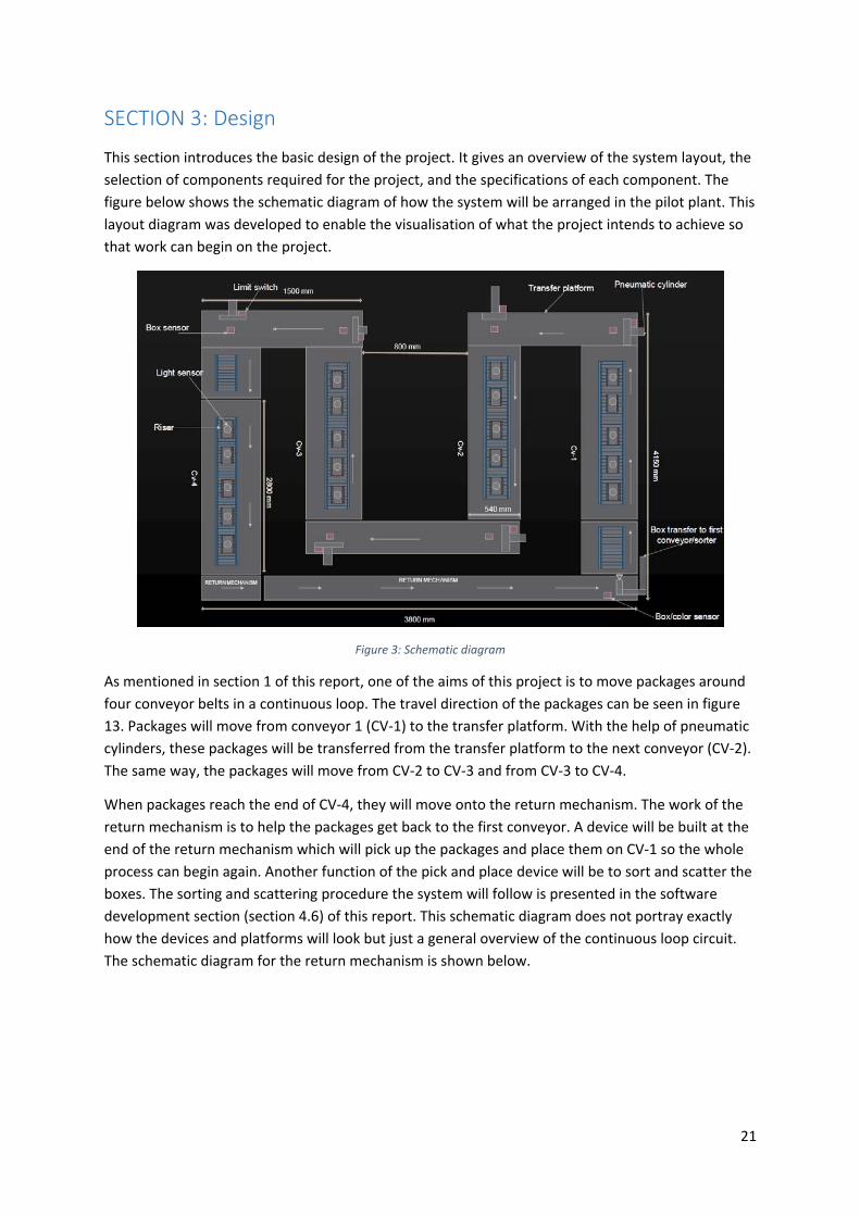
This section introduces the basic design of the project. It gives an overview of the system layout, the
selection of components required for the project, and the specifications of each component. The
figure below shows the schematic diagram of how the system will be arranged in the pilot plant. This
layout diagram was developed to enable the visualisation of what the project intends to achieve so
that work can begin on the project.
Figure 3: Schematic diagram
As mentioned in section 1 of this report, one of the aims of this project is to move packages around
four conveyor belts in a continuous loop. The travel direction of the packages can be seen in figure
13. Packages will move from conveyor 1 (CV‐1) to the transfer platform. With the help of pneumatic
cylinders, these packages will be transferred from the transfer platform to the next conveyor (CV‐2).
The same way, the packages will move from CV‐2 to CV‐3 and from CV‐3 to CV‐4.
When packages reach the end of CV‐4, they will move onto the return mechanism. The work of the
return mechanism is to help the packages get back to the first conveyor. A device will be built at the
end of the return mechanism which will pick up the packages and place them on CV‐1 so the whole
process can begin again. Another function of the pick and place device will be to sort and scatter the
boxes. The sorting and scattering procedure the system will follow is presented in the software
development section (section 4.6) of this report. This schematic diagram does not portray exactly
how the devices and platforms will look but just a general overview of the continuous loop circuit.
The schematic diagram for the return mechanism is shown below.

22
Figure 4: Return mechanism schematic diagram
Similar to the main schematic diagram, this was developed to show what the idea is about the return
mechanism. The top half of figure 4 shows the top and side view of the return mechanism. When the
box (package) gets onto the return mechanism, the platform with the two rod cylinders underneath
will rise. The rod‐less cylinder attached to the top of the rising platform will push the box onto the
roller conveyor. When the box gets to the end of the roller conveyor, the bottom half of figure 4
shows the schematic diagram of the device that will be used to pick and place the box back on the
first conveyor.
Once the schematic diagrams were developed, it became clear that certain components would be
necessary to complete this project. For example, the transfer platform would need to have
pneumatic cylinders, limit switches, box sensors, a controller, and directional control valves. The
selection process and specifications of the various components used for this project are discussed
below.
3.0 BOX SENSORS
When a package comes on the transfer platform, it is necessary to have a sensor that will detect this
package and send that information to a controller so the controller can send appropriate commands
to the actuators to move the package. After consultations with the project supervisor (Graeme Cole),
he suggested that as much as possible, components already available in the university should be
used and components should be purchased only when necessary. A meeting was therefore held with
Iafeta Laava (Murdoch University technical staff) to determine what sensors were available. He
(Iafeta Laava) was able to find retro‐reflective, inductive, capacitive, and photoelectric proximity
sensors from the Murdoch University Engineering store room.

23
After careful consideration of the different sensors, the retro‐reflective, and photoelectric proximity
sensors were selected. The reason for this is based on the fact that the sensors had to be directly
installed on wooden platforms and the capacitive and inductive proximity sensors output are
affected by wooden materials. Discussed below are the photoelectric and retro‐reflective sensors
selected for this project.
3.0.1 VTE18‐4P2740 PHOTOELECTRIC PROXIMITY SENSOR
There were two types of these sensors available in the Engineering store room. A picture of this
sensor is shown in the figure below.
Figure 5: VTE18‐4P2740 photoelectric proximity sensor
The sensor specification is shown in the table below.
Table 2: VTE18‐4P2740 photoelectric proximity sensor specification (SICK Sensor Intelligence, 2017)
Sensor/detection principle Photoelectric proximity sensor
Sensing range 3mm…..170mm
Sensing range max 3mm…..200mm
Adjustment Potentiometer, 270° (sensing range)
Supply Voltage 10 V DC…..30 V DC
Power consumption ≤30mA
Switching output PNP
Switching mode Light or dark switching selected vial L/D cable
Output current 100mA
Response time ≤2ms
Circuit protection Vs connections reverse‐polarity protected,
inputs/outputs reverse polarity protected,
outputs and short‐circuit protected
Frequency 250Hz
From table 3, it can be seen that this sensor has specifications suitable for this project: High
response time, high switching frequency, and the supply voltage range are good. Also, this type of
sensor has in‐built circuit protection which helps protect the sensor from damages especially for a
system that will be operated by various students after this thesis project. In addition, the high
response speed of the sensor means the sensor won't slow down the process. Refer to (SICK Sensor
Intelligence, 2017) for more detailed specifications of this sensor.

24
3.0.2 VTE18‐4N4240V PHOTOELECTRIC PROXIMITY SENSOR
Four VTE18‐4N4240V sensors were purchased for this project. This was because only two of the
VTE18‐4P2740 sensor were available in the Engineering store room and four more were needed. A
picture of this sensor and specification is shown in the figure and table below.
Figure 6: VTE18‐4N4240V photoelectric proximity sensor
Table 3: VTE18‐4N4240V photoelectric proximity sensor specification (SICK Sensor Intelligence, 2017)
Sensor/detection principle Photoelectric proximity sensor
Sensing range 5mm…..400mm
Sensing range max 0mm…..450mm
Adjustment Single teach‐in button (sensing range)
Supply Voltage 10 V DC…..30 V DC
Power consumption ≤35mA
Switching output NPN
Switching mode Light or dark switching selected vial L/D cable
Output current ≤100mA
Response time ≤1ms
Circuit protection Vs connections reverse‐polarity protected,
inputs/outputs reverse polarity protected,
outputs and short‐circuit protected
Frequency 500Hz
From the specification table above, it can be seen that this sensor is twice as fast and has a bigger
sensing range than the previous sensor. The sensors operate in a similar way, but a major difference
is that while the previous sensor (figure 14) has a PNP switching output, this sensor has an NPN
switching output. This has to be taken into consideration when installing the sensors. When a search
was made for a sensor similar to the ones found in the Engineering store room, this sensor was most
similar, in stock, and could arrive within three weeks of purchase. Thus the reason this sensor was
purchased. Refer to (SICK Sensor Intelligence, 2017) for more detailed specification of this sensor.
3.0.3 WT18‐2P2112 PHOTOELECTRIC PROXIMITY SENSOR
The two types of sensors discussed earlier were acquired to be installed on the transfer platforms.
This WT18‐2P2112 photoelectric proximity sensor was also found in the Engineering store room and
was acquired to be installed as the box sensor at the right‐end of the return mechanism. The return

25
mechanism requires two sensors, one at the left‐end and one at the right‐end. Shown below is a
picture of this sensor.
Figure 7: WT18‐2P112 photoelectric proximity sensor
The sensor specifications are given in the table below.
Table 4: WT18‐2P112 photoelectric proximity sensor specification (SICK Sensor Intelligence, 2017)
Sensor/detection principle Photoelectric proximity sensor
Sensing range 50mm…..700mm
Sensing range max 50mm…..700mm
Adjustment Potentiometer (sensing range)
Supply Voltage 10 V DC…..30 V DC
Power consumption ≤25mA
Switching output PNP
Switching mode Light or dark switching
Response time ≤700µs
Although the online data sheet of this sensor does not state that the sensor has circuit protection, it
still possesses vital attributes like the speed of response and sensing range adjustment which are
both important for this project. The lack of protection means extra care has to be taken so as not to
wrongly connect the sensor. Another notable feature of the sensor is the PNP switching output
which affects how the sensor will be connected.
3.0.4 WL11‐2N2430 PHOTOELECTRIC RETRO‐REFLECTIVE SENSOR
This sensor is a bit different from the other three sensors discussed earlier because it is not a
proximity sensor rather, it is a retro‐reflective sensor. This sensor was also sourced by Iafeta Laava
from the Engineering store room. For the left‐end box sensor of the return mechanism, this sensor
was acquired. A picture of this sensor is shown below.
Figure 8: WL11‐2N2430 retro‐reflective sensor

26
The sensor specifications are given below.
Table 5: WL11‐2N2430 retro‐reflective sensor (SICK Sensor intelligence, 2017)
Sensor/detection principle Photoelectric retro‐reflective sensor
Sensing range 0.15m…..8m
Sensing range max 0.15m…..10m
Adjustment None
Supply Voltage 10 V DC…..30 V DC
Power consumption ≤40mA
Switching output NPN
Switching mode Light or dark switching
Output current 100mA
Response time ≤2.5ms
Circuit protection Vs connections reverse‐polarity protected,
inputs/outputs reverse polarity protected,
outputs and short‐circuit protected
Frequency 200Hz
This sensor was chosen because it was readily available, and has specifications similar to that of the
other box sensors. Furthermore, because the system will be used for teaching purposes in the
future, it was important to make use of different types of components. Reflective tape was also
acquired to be used in conjunction with this sensor. Refer to (SICK Sensor intelligence, 2017) for a
more detailed specification of the retro‐reflective sensor.
3.1 COLOUR SENSORS
To achieve the colour sorting aim of this project, it is imperative to have a colour sensor.
Unfortunately, there were no colour sensors in the Engineering store room, so it had to be
purchased. The colour sensor selected for this project and its specification is shown in the figure and
table below.
Figure 9: CSM‐WP117A2P colour sensor

27
Table 6: CSM‐WP117A2P colour sensor specification (SICK sensor intelligence, 2017)
Sensing distance 12.5mm
Sensing distance tolerance ±3mm
Adjustment Teach in button
Supply Voltage 12 V DC…..24 V DC
Power consumption ˂ 50mA
Switching output PNP
Output current ˂ 100mA
Response time 300 µs
Circuit protection Vs connections reverse‐polarity protected,
inputs/outputs reverse polarity protected,
outputs and short‐circuit protected
Switching frequency 1.7kH
The supply voltage range and the response time of the sensor were the main reasons why this colour
sensor was selected. The teach‐in ability of the sensor is another attractive feature of the sensor
because it makes the sensor flexible and not fixed to a particular colour. The sensor was also
available to be delivered within one week. All the components selected so far can all operate on
24VDC which eliminates the need for extra circuitry needed to operate devices that run at different
voltage levels. Four of this sensor was purchased from RS components to be used for this project.
3.2 TRANSPORT PACKAGE
The transport package is what will be conveyed and sorted around the four conveyors. Based on the
width of the conveyor belts and the size of the risers, it was decided that the transport package
should be a 200mm by 200mm by 200mm box and have an approximate weight of 2kg. Ten coloured
boxes were made by Graham Malzer and Mark Burt (Murdoch University Engineering Technical
Staffs), so they can be used as test materials for the system. A vendor was also contacted to produce
16 boxes made out of polycarbonate and covered with coloured acrylics which would be used for
the final implementation of the transport and sorting task. Shown below is a picture of one of the
boxes made for initial testing and the final box supplied by a vendor.
Figure 10: Initial box made for testing
Figure 11: Box supplied by a vendor for final implementation

28
3.3 PNEUMATIC CYLINDERS
Pneumatic cylinders were needed for this project for pushing the boxes across the transfer platforms
and for picking and placing the boxes. A decision was made to use rod‐less pneumatic cylinders for
the transfer platforms, and the pick and place device will make use of both a rod‐less and rod
cylinder. This decision was based on the fact that rod‐less cylinders don't need as much space to
install when compared to rod cylinders. If a rod cylinder was selected, extra space would be required
for the cylinder and extension of the piston while a rod‐less cylinder has no piston that extends out
of the cylinder. Pneumatic and not hydraulic cylinders were selected because there are several air
supply outlets in the Murdoch University Pilot Plant. Additionally, pneumatic systems are clean,
easier to install and maintain, cheaper than hydraulic systems, and this project does not require the
generation of very large forces (Gupta, Arora, & Wescott, 2017).
A total of twelve cylinders were required. Eight rod‐less cylinders; seven for the transfer platforms
and one for the pick and place device, and four rod cylinders; two for one of the transfer platforms
and two for the pick and place device. However, only eight cylinders could be sourced from the
Engineering store room which meant the remaining four cylinders would have to be purchased. The
list of the cylinders sourced from the Engineering store room is given below.
One 1000mm stroke length magnetically coupled rod‐less cylinder
three 400mm stroke length mechanically coupled rod‐less cylinder
Two 250mm stroke length rod cylinder
Two 400mm stroke length rod cylinder
After the acquisition of the cylinders listed above, a calculation was done to determine if the piston
force of the cylinders will be able to move 2kg boxes. This calculation was done using the cylinder
with the smallest surface area (the 400mm stroke length mechanically coupled rod‐less cylinder
sourced from the Engineering storeroom) because if this cylinder has enough force to move the
boxes, the other bigger cylinders will be able to do the same. The required force to move 2kg boxes
horizontally is given below.
𝐹 𝜇. 𝑚. 𝑔
Where,
𝐹 𝐹𝑜𝑟𝑐𝑒 𝑟𝑒𝑞𝑢𝑖𝑟𝑒𝑑 𝑡𝑜 𝑚𝑜𝑣𝑒 𝑡ℎ𝑒 𝑏𝑜𝑥 ℎ𝑜𝑟𝑖𝑧𝑜𝑛𝑡𝑎𝑙𝑙𝑦 𝑁
µ 𝐶𝑜𝑒𝑓𝑓𝑖𝑐𝑖𝑒𝑛𝑡 𝑜𝑓 𝑓𝑟𝑖𝑐𝑡𝑖𝑜𝑛
𝑔 𝐴𝑐𝑐𝑒𝑙𝑒𝑟𝑎𝑡𝑖𝑜𝑛 𝑑𝑢𝑒 𝑡𝑜 𝑔𝑟𝑎𝑣𝑖𝑡𝑦 9.8𝑚/𝑠
𝑚 𝑀𝑎𝑠𝑠 𝑜𝑓 𝑡ℎ𝑒 𝑏𝑜𝑥 2𝑘𝑔
The final boxes for the implementation will be covered in coloured acrylic and will have to move on
steel ball transfer units. The coefficient of static friction for acrylic on dry steel is 0.4 (eMachine
shop, n.d.). Therefore,
𝐹 0.4 ∗ 2 ∗ 9.8
𝐹 7.84𝑁
Theoretical force of a pneumatic drive is given as;

29
𝐹 𝐴. 𝑃
Where,
𝐴 𝑠𝑢𝑟𝑓𝑎𝑐𝑒 𝑎𝑟𝑒𝑎𝜋. 𝐷
4
𝑠𝑚𝑎𝑙𝑙𝑒𝑠𝑡 𝑏𝑜𝑟𝑒 𝑠𝑖𝑧𝑒 𝑓𝑟𝑜𝑚 𝑠𝑒𝑙𝑒𝑐𝑡𝑒𝑑 𝑐𝑦𝑙𝑖𝑛𝑑𝑒𝑟𝑠 𝐷 25𝑚𝑚 0.025𝑚
𝐴3.142 ∗ 0.025
40.00049𝑚
𝑝 𝑐𝑦𝑙𝑖𝑛𝑑𝑒𝑟 𝑝𝑟𝑒𝑠𝑠𝑢𝑟𝑒 100𝑘𝑝𝑎 𝑚𝑖𝑛𝑖𝑚𝑢𝑚 𝑝𝑟𝑒𝑠𝑠𝑢𝑟𝑒 𝑎𝑠𝑠𝑢𝑚𝑝𝑡𝑖𝑜𝑛
𝐹 0.00049 ∗ 100000 49𝑁
The effective force is given as;
𝐹 𝐹 𝐹
𝐹 𝑓𝑟𝑖𝑐𝑡𝑖𝑜𝑛 𝑓𝑜𝑟𝑐𝑒 𝑟𝑜𝑢𝑔ℎ𝑙𝑦 10% 𝑜𝑓 𝑡ℎ𝑒𝑜𝑟𝑒𝑡𝑖𝑐𝑎𝑙 𝑓𝑜𝑟𝑐𝑒 Haring, Metzger, & Weber, 2013 .
𝐹 0.1 ∗ 49 4.9𝑁
Therefore,
𝐹 49 4.9 44.1𝑁
From the calculated effective force of the cylinder with the smallest area and with a very small
cylinder pressure assumption, it can be seen that the cylinder can generate more than enough force
to move the boxes horizontally.
The remaining four cylinders were found online. Selecting the cylinders to purchase was based on
the time it would take to arrive, the bore size, and the price (reasonable) of the cylinder. Listed
below are the cylinders purchased.
Three 200mm stroke length mechanically coupled rod‐less cylinder
One 800mm stroke length mechanically coupled rod‐less cylinder.
Pictures and installation of the cylinders are in section 4 of this report. Also, all the cylinders
acquired are double acting cylinders.
3.4 DIRECTIONAL CONTROL VALVES
Ten solenoid directional control valves were required. A 5/3 closed‐center solenoid valve was
selected because it was necessary to have a valve that can control the double acting cylinders and
stop them midway if necessary. For example, if the solenoid should suddenly lose power, the
pneumatic cylinder would stop at whatever position it was when the valve lost power. Two out of
the needed eleven were found in the Engineering store room, and eight were purchased with the
help of a Murdoch University technical staff (Iafeta Laava).
Ten of the eleven solenoid valves were acquired to control the cylinders while the last solenoid valve
was acquired to control the air flow from the vacuum pump. Details about the last solenoid valve,

30
vacuum pump, and gripper are given in section 3.5 (vacuum technology sub heading of this report).
The figure below shows the 5/3 solenoid valve used for this project.
Figure 12: 5/3 solenoid valve
3.5 VACUUM TECHNOLOGY
When the box gets to the end of the return mechanism, it has to be picked up and placed on the first
conveyor. To achieve the pick and place goal, vacuum technology was used. To determine the force
required to pick up the box and move it horizontally, the following calculation was done;
𝑓𝑜𝑟𝑐𝑒 𝑟𝑒𝑞𝑢𝑖𝑟𝑒𝑑 𝑡𝑜 𝑝𝑖𝑐𝑘 𝑢𝑝 𝑡ℎ𝑒 2𝑘𝑔 𝑏𝑜𝑥 𝐹 𝑚. 𝑔 𝑎 . 𝑆
𝑆 𝑠𝑎𝑓𝑒𝑡𝑦 𝑓𝑎𝑐𝑡𝑜𝑟 1.5 𝑓𝑜𝑟 𝑣𝑒𝑟𝑡𝑖𝑐𝑎𝑙 𝑎𝑛𝑑 ℎ𝑜𝑟𝑖𝑧𝑜𝑛𝑡𝑎𝑙 𝑚𝑜𝑣𝑒𝑚𝑒𝑛𝑡 Festo, 2006 .
𝑎 𝑒𝑚𝑝𝑒𝑟𝑖𝑐𝑎𝑙 𝑣𝑎𝑙𝑢𝑒 𝑓𝑜𝑟 𝑎𝑐𝑐𝑒𝑙𝑒𝑟𝑎𝑡𝑖𝑜𝑛 𝑜𝑓 𝑝𝑛𝑒𝑢𝑚𝑎𝑡𝑖𝑐 𝑠𝑦𝑠𝑡𝑒𝑚 Festo, 2006 30𝑚/𝑠
𝐹 2 ∗ 9.8 30 ∗ 1.5 119𝑁
The force required to move it horizontally is given as (Festo, 2006);
𝐹 𝑚. 𝑔𝑎𝜇
. 𝑆
𝐹 2 ∗ 9.8300.4
∗ 1.5 254.4𝑁
3.5.1 VACUUM PUMP
A 12VDC vacuum pump was acquired to be used to generate the required vacuum needed to pick up
the boxes. The figure below shows the vacuum pump acquired.
Figure 13: 12V‐DC Vacuum pump
31
3.5.2 GRIP VALVE
The vacuum pump discussed above is used to create a vacuum in a suction cup, and when the pump
is turned off, the vacuum created will remain. This means that it will not be possible to drop the box
by turning off the vacuum pump. A solenoid valve will be able to change the air flow direction when
it is needed to drop the box. To pick up the box, the solenoid valve will direct the air flow from the
suction through the vacuum pump. To drop the box, the solenoid valve will direct the air flow from
the suction toward the atmosphere thereby removing the vacuum created by the vacuum pump.
The figure below shows the solenoid valve acquired for this purpose.
Figure 14: 12VDC Solenoid valve used for gripping
3.5.3 SUCTION CUP
There are different types of suction cups used in vacuum technology. The type of suction cup
selected is dependent on the application. A standard suction cup was selected for this project
because it is suitable for flat surfaces (Festo, 2006). A 125mm diameter standard suction cup was
proposed, but before the suction cup was purchased, the calculation shown below was carried out
to determine if a suction cup of that size can generate the required force needed to pick up and
move the boxes.
From previous calculations,
𝑓𝑜𝑟𝑐𝑒 𝑟𝑒𝑞𝑢𝑖𝑟𝑒𝑑 𝑡𝑜 𝑝𝑖𝑐𝑘 𝑢𝑝 𝑡ℎ𝑒 2𝑘𝑔 𝑏𝑜𝑥 119𝑁
𝑓𝑜𝑟𝑐𝑒 𝑟𝑒𝑞𝑢𝑖𝑟𝑒𝑑 𝑡𝑜 𝑚𝑜𝑣𝑒 𝑡ℎ𝑒 𝑏𝑜𝑥 ℎ𝑜𝑟𝑖𝑧𝑜𝑛𝑡𝑎𝑙𝑙𝑦 254.4𝑁
𝑝𝑖𝑐𝑘 𝑢𝑝 𝑓𝑜𝑟𝑐𝑒 ℎ𝑜𝑟𝑧𝑜𝑛𝑡𝑎𝑙 𝑚𝑜𝑣𝑒𝑚𝑒𝑛𝑡 𝑓𝑜𝑟𝑐𝑒 119 254.4 373𝑁
From the specification of the vacuum pump,
𝑚𝑎𝑥𝑖𝑚𝑢𝑚 𝑣𝑎𝑐𝑢𝑢𝑚 𝑔𝑒𝑛𝑒𝑟𝑎𝑡𝑒𝑑 𝑏𝑦 𝑝𝑢𝑚𝑝 𝑃 16 𝐻𝑔 54182.2𝑃𝑎
𝑑𝑖𝑎𝑚𝑒𝑡𝑒𝑟 𝑜𝑓 𝑡ℎ𝑒 𝑝𝑟𝑜𝑝𝑜𝑠𝑒𝑑 𝑠𝑢𝑐𝑡𝑖𝑜𝑛 𝑐𝑢𝑝 125𝑚𝑚
𝑒𝑓𝑓𝑒𝑐𝑡𝑖𝑣𝑒 𝑑𝑖𝑎𝑚𝑒𝑡𝑒𝑟 𝑜𝑓 𝑝𝑟𝑜𝑝𝑜𝑠𝑒𝑑 𝑠𝑢𝑐𝑡𝑖𝑜𝑛 𝑐𝑢𝑝 Festo, 2017 105𝑚𝑚 0.105𝑚
𝐴𝑟𝑒𝑎 𝑜𝑓 𝑝𝑟𝑜𝑝𝑜𝑠𝑒𝑑 𝑠𝑢𝑐𝑡𝑖𝑜𝑛 𝑐𝑢𝑝 𝐴𝜋𝑑
4

32
𝐴3.142 ∗ 0.105
4 0.00866𝑚
Therefore,
𝑠𝑢𝑐𝑡𝑖𝑜𝑛 𝑓𝑜𝑟𝑐𝑒 𝐹 𝐴 ∗ 𝑃 0.00866 ∗ 54182.2
𝐹 469𝑁
From the result obtained above, the suction force (469N) is greater than the force required to pick
up the box and move it horizontally (373N). Therefore, the 125mm diameter Festo standard suction
cup was purchased. The figure below shows the suction cup.
Figure 15: Suction cup
3.6 CONTROLLER AND COMMUNICATION DEVICE
Initially, the plan was to use a programmable logic controller for this project. However, to install
PLCs on each conveyor and transfer platforms will be very costly and networking the PLCs together
will be time‐consuming. After discussions with the project supervisor, it was decided that the option
of using input/output (I/O) devices that can easily be networked together should be considered. The
project supervisor also advised that research be done on ADVANTECH ADAM MODULES because
some of the modules were already in use in the PV training facility at Murdoch University. After
estimating the number of inputs and outputs each conveyor and transfer platform would need, the
ADAM 6052 I/O module was proposed. The 6052 modules are portable, easy to install, have speeds
of up to 100mbps, and supports the Modbus TCP/IP communication protocol. With the help of Will
Stirling (Murdoch University technical staff), nine ADAM 6025 I/O modules were purchased.
Figure 16: ADAM 6052 I/O module with specifications (ADVANTECH Co. Ltd, n.d.)

33
The portable nature of this device means it can easily be installed in small spaces. As this project
progressed, the nine modules were no longer sufficient. Consequently, two additional ADAM
modules were acquired. The 6052 modules were not available anymore, so the ADAM 6250 module
was purchased. There are similarities and differences between the two modules. One of the main
difference is that the 6250 module has a lower output current when compared to the 6052 module.
The figure below shows the ADAM 6250 module and its specifications.
Figure 17: ADAM 6250 with specifications (ADVANTECH Co. Ltd, n.d.)
These modules will be used to collect data from sensors and send signals to the actuators. A
computer will be used as the controller, and a program will be developed using the LabVIEW
programming environment.
The I/O modules are equipped with Ethernet ports. Ethernet cables and a network switch were
purchased by Will Stirling, and he also helped install a separate network card in the computer to
support these I/O modules. This was to make it possible to create a separate network for the ADAM
modules that will not interfere with the University IT network.
3.7 OTHER COMPONENTS
Listed below are some other components purchased or sourced for this project.
1. Air flow regulators
2. Buck converters
3. Push buttons
4. Indicator lights
5. Buzzer
6. Fuses
7. Terminals
8. Labelling kit
9. Emergency stop valves, and switches
10. Relays, and Electric wires
11. Ball transfer units
12. Din rail, Duct and Strut channel
13. Circuit breakers
14. Pipes, Nuts, and bolts

34
How various components were put together to achieve the aim of this project is discussed in the
next section of this report.

35
SECTION 4: Implementation
This part of the report talks about how the various components were put together. The transfer
platforms and return mechanism building, wiring, and testing are also discussed in this section. The
construction aspect of the implementation was made possible with help and advice from Graham
Malzer (Murdoch University technical staff) because it involved considerable physical construction
work for which he has much experience.
4.0 I/O MODULES AND COLOUR SENSOR CONFIGURATION
ADAM 6052 and 6250 I/O modules use IP addresses for identification on the network. As can be
seen from the specification of the 6052/6250 module (figure 26 and 27), the inputs can be set to
either dry or wet contact. It is possible to set some inputs for wet contact and others as dry contact.
Setting the input as dry contact means the input will go high when it is connected to the module's
DGND while setting the input as wet contact means the input will work with an external power
supply and can be made to go high when grounded or connected to the supply voltage. DCOM is
used for wet contact input setting. Due to the use of sensors in this project which require their
power supply to function, the inputs of the 6052 and 6250 I/O modules were set for wet contact
connection. The 6052 units had to be opened up to manually adjust the jumpers to set it to wet
contact. The figure below shows the jumpers used for this setting.
Figure 18: ADAM 6052 module Input setting
The 6250 modules which were purchased later did not require the modules to be opened up to
change the input settings. It has a switch by the side of the module which is used to set the inputs
for dry or wet connection.
Figure 19: ADAM 6250 module input setting

36
Setting the IP address of the modules is done through the ADAM.net utility software. The steps
required for the module configuration are listed below.
1. Power up the module by connecting supply voltage to the (R)+Vs and B(GND) connection
terminal on the module
2. Connect the module to the computer using an Ethernet cable: connection should be made
to the network card separate from the school network
3. Open the ADAM.net utility software
4. Search for the module on the network it has been connected to: the network card has an IP
address. Therefore, the search has to be done under that IP address. The network card used
for this project has an IP address of 192.168.1.0.
5. Select the module which appears on that network. The module has a default IP address of
10.0.0.0.
6. Enter 00000000 as the password to open the module. This is the default password and was
not changed for this project
7. Change the IP address to an address with the same subnet mask as the network address.
The last digit of the IP address is the unique identifier of the module. Example: the network
address for this project is 192.168.1.0. One of the modules was given an address of
192.168.1.10 which means that the unique identifier for that module is the number 10.
8. Make any other changes as required and disconnect the module
The steps listed above were followed in configuring the 6052 modules. However, during this process,
there was an issue with the ADAM.net utility software not being able to discover the modules. It was
later discovered that is was because even if the network card was separate from the school’s
network, it was still causing issues with the firewall settings of the computer. To resolve this, a
computer which was completely isolated from the school’s network was used to complete the
module configurations. Refer to (ADVANTECH Co. Ltd, 2011) and (ADVANTECH Co. Ltd, 2015) for
more details about the I/O modules.
The IP addresses of the modules used in this project and the platforms they are attached to is given
in the table below.
Table 7: IP addresses and platform attached
IP ADDRESS PLATFORM ATTACHED
192.168.1.20 Sorting mechanism
192.168.1.19 Sorting mechanism
192.168.1.18 Control unit
192.196.1.17 Transfer platform 4 (TP‐4)
192.168.1.16 Transfer platform 1 (TP‐1)
192.168.1.15 Conveyor 1 (CV‐1)
192.168.1.14 Conveyor 2 (CV‐2)
192.168.1.13 Transfer platform 2 (TP‐2)
192.168.1.12 Conveyor 3 (CV‐3)
192.168.1.11 Conveyor 4 (CV‐4)
192.168.1.10 Transfer platform 3 (TP‐3)
The network topology of the conveyor system is shown in the figure below.

37
Figure 20: Network topology
There were some issues encountered while trying to communicate with the modules using LabVIEW
software. These issues are discussed in section 5 of this report.
The colour sensors were configured to detect the following colours; yellow, orange, purple, and
green. However, the sensors were not able to properly distinguish between the purple and green
colour. When a green box was placed in front of the sensors, the output of the sensor configured to
detect green colour and the sensor configured to detect purple colour was activated. Therefore, it
was decided that the conveyor system would make use of two sensors and sort boxes according to
three colours. Refer to (SICK sensor intelligence, 2017) for more information about the sensor
configuration
4.1 TRANSFER PLATFORM 1, 2, AND 3
Transfer platforms 1, 2, and 3 were built in a similar way. The figures used in describing how the
platforms were built consist of a combination of pictures taken during the development of the three
platforms. The logic on how the transfer platforms will operate is described later in the software
development part of this report.
Holes were drilled into the side of the conveyor system, and strut channels were attached using
bolts and nuts. The attachment was made to provide a base so that a wooden platform can be
placed on it and a second wooden platform was attached to the top of the first wooden platform.
The top platform was made to be adjustable so that it can be aligned with the height of the conveyor
belt. Two pneumatic cylinders and two directional control valves were installed on the base
platform. Two sensors and three limit switches were installed on the top platform. The sensors were
installed to signal the presence of a box on the platform, and the limit switches were installed to
determine the position of the cylinder. The cylinder used to push the box horizontally has two limit

38
switches while the cylinder for pushing the box vertically has one limit switch. A part of the top
platform was cut open to allow for the pusher to extend from the cylinders attached to the base
platform. 25mm diameter holes were also drilled on the top platform so that the ball transfer units
can be installed. The purpose of the ball transfer unit is to help the boxes roll smoothly on the
platform.
Figure 21: Base and top view of platform under construction
The figure above shows the bottom side of the top platform, and the top side of the base platform
under construction. Shown below is the strut channel which supports the base platform.
Figure 22: Base platform support made using strut channels
Once the top and bottom platforms were securely bolted, one ADAM 6052 I/O module was installed
on each of the platforms for controlling the movement of the cylinders. The sensors installed on
transfer platforms 1, 2, and 3 are the photoelectric proximity sensors. Guides were installed on the
top platform to ensure the boxes do not fall off the platform. The wiring was done neatly with the
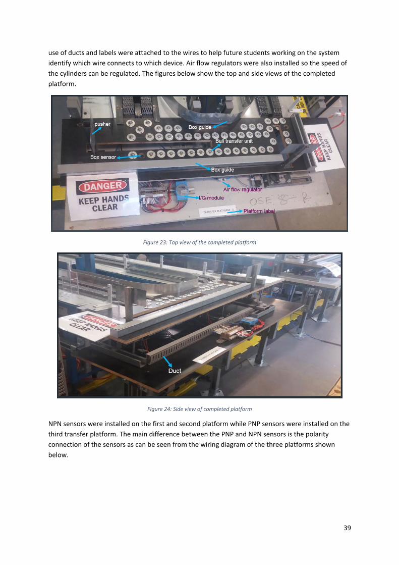
39
use of ducts and labels were attached to the wires to help future students working on the system
identify which wire connects to which device. Air flow regulators were also installed so the speed of
the cylinders can be regulated. The figures below show the top and side views of the completed
platform.
Figure 23: Top view of the completed platform
Figure 24: Side view of completed platform
NPN sensors were installed on the first and second platform while PNP sensors were installed on the
third transfer platform. The main difference between the PNP and NPN sensors is the polarity
connection of the sensors as can be seen from the wiring diagram of the three platforms shown
below.

40
Figure 25: Transfer platform 1 wiring diagram
Figure 26: Transfer platform 2 wiring diagram

41
Figure 27: Transfer platform 3 wiring diagram
The meaning of the abbreviations used in the wiring diagrams are listed below. Except for the ones
specially related to a particular platform, all other abbreviations and meanings are the same for the
three platforms.
ABBREVIATIONS AND MEANINGS
LC‐C ‐‐‐‐‐‐‐ left cylinder contracted (LS1) (Transfer platform 1 and 3)
LC‐EX ‐‐‐‐‐‐ left cylinder extended (LS2) (Transfer platform 1 and 3)
RCB ‐‐‐‐‐‐‐ right cylinder back (LS3) (Transfer platform 1 and 3)
RC‐C ‐‐‐‐‐‐‐ right cylinder contracted (LS1) (Transfer platform 2)
RC‐EX ‐‐‐‐‐‐ right cylinder extended (LS2) (Transfer platform 2)
LCB ‐‐‐‐‐‐‐ left cylinder back (LS3) (Transfer platform 2)
LS1 ‐‐‐‐‐‐ limit switch 1
LS2 ‐‐‐‐‐‐ limit switch 2

42
LS3 ‐‐‐‐‐‐ limit switch 3
LCV ‐‐‐‐‐‐‐ left control valve
RCV ‐‐‐‐‐‐‐ right control valve
LCMR ‐‐‐‐‐‐ left cylinder move right LCV coil
LCML ‐‐‐‐‐‐‐ left cylinder move left LCV coil
RCMB ‐‐‐‐‐‐‐ right cylinder move back RCV coil
RCMF ‐‐‐‐‐‐‐ right cylinder move forward RCV coil
RBS ‐‐‐‐‐‐‐ right box sensor
LBS ‐‐‐‐‐‐‐ left box sensor
D‐S ‐‐‐‐‐‐‐ dark switching (switches when dark)
L‐S ‐‐‐‐‐‐‐ light switching (switches when bright)
L/D SELECTOR ‐‐‐‐‐‐‐ switches between light (L‐S) and dark (D‐S) switching
For better understanding of the wiring diagrams and abbreviations, refer to section 4.5, the software
development part of this report which shows the view point of the project. The view point will help
explain the meaning of ‘’move right’’ and ‘’move left’’ because left and right can easily be
misunderstood if viewed from the wrong position.
4.2 RETURN MECHANISM
As shown in figure 14 (design section of this report), the return mechanism is divided into three
parts. The platform which moves up and down, the roller conveyor, and the pick and place device.
Discussed in this part of the report, are the three parts of the return mechanism.
4.2.1 TRANSFER PLATFORM 4
The platform which moves up and down is called transfer platform 4. A base was built using concrete
to make the platform stable. Two pneumatic cylinders were attached to the base, and a platform
was attached to the top of the two cylinders. These cylinders were installed to lift and drop the
platform when a box arrives on the platform. A wooden board was attached to the side of the base,
and another cylinder was installed on the board to push the boxes onto the roller conveyor. Four
limit switches were attached to this platform, two to detect the up and down position, and two to
detect the left and right position of the cylinders. On the back of the board attached to the side of
the base, two control valves, and an ADAM 6052 I/O module was installed. The box sensor used for
this platform is the retro‐reflective sensor.

43
Figure 28: Front view of transfer platform 4
Figure 29: Back and side view of transfer platform 4

44
This platform was also fitted with air regulators, and the wiring was properly labelled for future
references. The wiring diagram of transfer platform four is shown below.
Figure 30: Transfer platform 4 wiring diagram
ABBREVIATIONS AND MEANINGS
P‐DOWN‐‐‐‐‐‐‐ Platform down (LS1)
P‐UP ‐‐‐‐‐‐ Platform up (LS2)
CTRD ‐‐‐‐‐‐‐ Contracted (right position) (LS3)
EXTD ‐‐‐‐‐‐‐ Extended (left position) (LS4)
BXS ‐‐‐‐‐‐‐ Box sensor
MV‐UP ‐‐‐‐‐‐ Move‐up
MV‐DN ‐‐‐‐‐‐‐ Move down
MV ‐‐‐‐‐‐‐ Move
U/D‐V ‐‐‐‐‐‐‐ Up/Down control valve
R/L‐V ‐‐‐‐‐‐‐ Right/Left control valve

45
4.2.2 ROLLER CONVEYOR
The roller conveyor used in this project was found in the pilot plant. The only adjustment that was
made to roller conveyor was the height. The elevation angle was increased to make it easier for the
boxes to roll on the conveyor. Transfer platform 4 transfers the boxes onto the roller conveyor and
when the boxes reaches the end of the roller conveyor, they are picked up by the pick and place
device. The purpose of the roller conveyor is to help the boxes get to the pick and place device.
Figure 31: Roller conveyor
4.2.3 PICK AND PLACE SYSTEM
The pick and place device was developed to transfer the boxes from the roller conveyor to the first
conveyor (CV‐1) and also sort them according to their colours. A lot of consideration was put into
developing this platform because of its size and function. Two rod and one rod‐less cylinder were
installed on this platform. The rod‐less cylinder was installed on top of the platform, and the rod
cylinders were attached to the side of the platform. When the rod‐less cylinder moves left or right, it
pulls the rod cylinders along with it because the three cylinders were coupled together. The
mechanism which connects the two cylinders were fitted with rollers so it can roll on the platform
when pulled by the rod‐less cylinder. A suction cup was attached to the two rod cylinders. Therefore,
when the rod cylinders move up or down, the suction cup will do the same, and if a box has been
gripped by the suction cup, it will move up and down as well. Three magnetic reed switches were
attached to the top of the platform to determine the position of the rod‐less cylinder ( left, right,
and middle) while two magnetic reed switches were attached to the side platform to determine the
position of the rod cylinders (up, and down). As a result of the movement of the wires and air pipes
connected to the cylinders, drag chains were installed on the system to keep the wires intact while
they move. The cylinders attached to the platform and the connection mechanism can be seen in the
figures below.

46
Figure 32: Top view of the pick and place device
Figure 33: Front view of the pick and place mechanism
As can be seen in figure 43, there is a middle platform between the end of the roller conveyor and
the first conveyor belt. The function of the holding tray is to hold the boxes during the colour sorting
process. One box sensor and four colour sensors were attached to the end of the roller conveyor for
detecting the presence, and colour of the boxes. Due to the number of inputs needed for this
system, two I/O modules were installed on the side of the system. A 12VDC vacuum pump and grip
valve were also installed on the side of the system. The vacuum pump was installed to create the
vacuum needed to lift the boxes while the grip valve was installed to direct the air flow for gripping
and releasing the boxes. When the suction is activated, the pump is turned on to create the vacuum,
and the grip valve connects the flow from the pump to the suction cup, and when the suction is
deactivated, the pump is turned off, and the grip valve connects the flow from the suction pump to
the atmosphere. A buck converter was used to step down the 24VDC to 12VDC needed to power the
pump and grip valve. The figures below show the side of the system and the sensors.
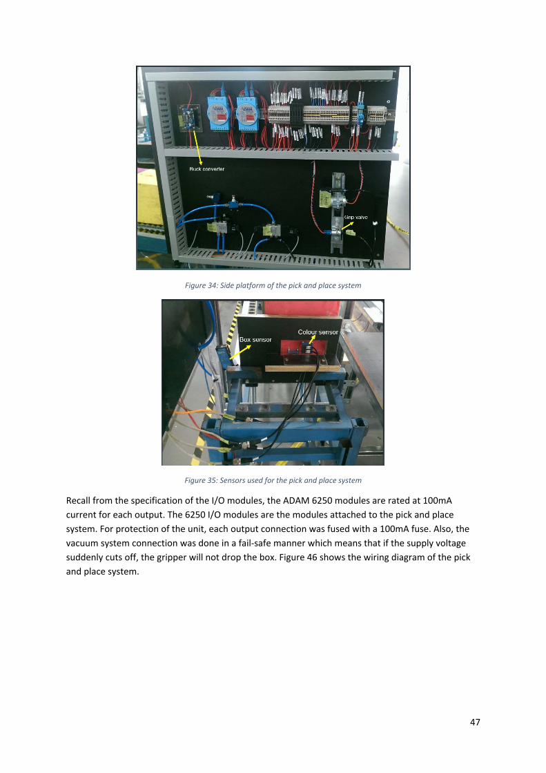
47
Figure 34: Side platform of the pick and place system
Figure 35: Sensors used for the pick and place system
Recall from the specification of the I/O modules, the ADAM 6250 modules are rated at 100mA
current for each output. The 6250 I/O modules are the modules attached to the pick and place
system. For protection of the unit, each output connection was fused with a 100mA fuse. Also, the
vacuum system connection was done in a fail‐safe manner which means that if the supply voltage
suddenly cuts off, the gripper will not drop the box. Figure 46 shows the wiring diagram of the pick
and place system.

48
Figure 36: Pick and place system wiring diagram
ABBREVIATIONS AND MEANINGS
DLS ‐‐‐‐‐‐ Down limit switch
ULS ‐‐‐‐‐‐ Up limit switch
MLS ‐‐‐‐‐‐ Middle limit switch
LLS ‐‐‐‐‐‐‐ Left limit switch
RLS ‐‐‐‐‐‐‐ Right limit switch
MV‐UP/MV‐DN ‐‐‐‐‐‐‐ Move up/move down

49
MV‐LEFT/ MV‐RIGHT ‐‐‐‐‐‐‐ Move left
MBXS ‐‐‐‐‐‐‐ Middle box sensor
BXS ‐‐‐‐‐‐‐ Box sensor
CS ‐‐‐‐‐‐‐ Colour sensor
4.3 CONVEYOR WIRING
The previous students that worked on the conveyor belts did so with the idea that the conveyor
belts will be hooked up to a PLC. Hence, the wiring of the conveyors needed to be adjusted in such a
way that it can be hooked up to an ADAM I/O module. The three‐phase wiring of the conveyor
system was done by Graham Malzer and enclosed in a separate box because students are not
permitted to work with three‐phase power supply (dangerous voltage). However, the contactor
terminals that control the power supply to the conveyor motor was provided in the wiring cabinet
which is accessible by students.
An ADAM 6052 I/O module was installed on each of the four conveyor belts. The modules were
installed to detect the status of the light sensors attached to the conveyor belts, control the
conveyor risers to stop the boxes when necessary, and make it possible to use a computer to turn
the conveyor belts on or off. Also, the wiring was done in such a way that it is still possible to turn
the belts on or off using the control buttons on the conveyor system. A picture of an I/O module
installed on one of the conveyor belts is shown below.
Figure 37: I/O module installed on the conveyor system

50
Figure 38: conveyor I/O module wiring diagram
The conveyor three‐phase wiring diagram is in appendix A of this report.
4.4 CONTROL UNIT AND I/O COMMUNICATION
A control unit was built for this conveyor sorting system. The aim of this unit is to have a central
point where the system can be operated and monitored. The control unit was placed at the midpoint
of the four conveyors. The various devices installed in the control unit are listed below.
A flashing light to indicate when the system is running
A buzzer to indicate the start‐up of the system
lights to indicate the current task being executed by the system
24VDC main switch
24VAC main switch
Power distribution terminals to the various sub systems
Emergency stop switch
System start button
System stop button
One ADAM 6250 I/O module
The power supply from the distribution boards (details in section 4.5, emergency shutdown aspect
of this report) comes into the control unit and from the control unit, it is distributed to the various

51
sub‐systems. All the supply lines to the sub‐systems have a 1A fuse for protection of the sub‐system
devices. Activating the start or stop button will send a signal through the I/O module to the
computer which will then send signals to the sub‐systems to start or stop the process. A signal is
sent to the control unit I/O module to turn on a light in correspondence to the task being carried
out. The only light not controlled by the I/O module in the control unit is the emergency stop light
which is hardwired to the emergency stop circuit.
All the I/O modules used in this project are connected via Ethernet cables to a network switch
located in the control unit. The control computer is also connected to the network switch, and
Modbus TCP/IP communication protocol is used for communicating with the various modules
through the network switch.
Figure 39: Back view of the control unit
Figure 40: Front view of the control unit

52
The wiring diagram of the control unit is given below.
Figure 41: Control unit wiring diagram
ABBREVIATIONS AND MEANINGS
ML ‐‐‐‐‐‐ Main light (system running indication)
W.F.S ‐‐‐‐‐‐ Wait for start button indication
INIIT ‐‐‐‐‐‐ Initialise state indication
S.T ‐‐‐‐‐‐‐ Simple transfer state indication
SORT ‐‐‐‐‐‐ Sorting state indication
SCATTER ‐‐‐‐‐‐‐ Scatter state indication
E‐STOP ‐‐‐‐‐‐‐ Emergency stop
4.5 DISTRIBUTION BOARDS AND EMERGENCY SHUT DOWN
Each conveyor system has a three‐phase motor and therefore, each requires a three‐phase power
connection outlet. The contactor of the three‐phase motor is powered by 24VAC, and the other
components of the conveyor sorting system require a 24VDC power supply. Due to the power
requirement of the system, two distribution boards were built. Again, because students are not
permitted to wire three‐phase systems, Graham Malzer (the technician) developed the distribution
boards after several meetings were held to determine the system requirements.

53
A three‐phase power supply is connected to the first distribution board (DB‐1) and the second
distribution board (DB‐2) power supply is derived from DB‐1. Inside the distribution boards are
circuit breakers and fuses for protection. The DC and AC power supply distributed to the sub systems
via the distribution terminals in the control unit is obtained from DB‐1 and DB‐2 respectively. The
conveyor system was fitted with three emergency stop switches that are manually operated,
automatic lock‐off manual reset types. Two of the switches are located in front of DB‐1 and DB‐2
while the third emergency stop switch is located in the control unit. If one of the emergency stop
switches is activated, the system can only return to normal operation if a reset button inside DB‐1 is
pushed. Only a technical staff member can assess the rest button. At the back of DB‐1 and DB‐2 are
24V AC and DC supply outlets that can be assessed by students.
Three emergency stop solenoid valves were also installed on the system. Two of the valves are for
blocking the air supply and venting the air out of the system in case of an emergency while the third
valve was installed so that the air supply can be controlled from the computer during normal
operation. A conveyor safety guide was consulted before the E‐stop procedure was developed
(Mining and Quarrying Occupational Health and Safety Committee, 2017). The system was also
developed to be fail‐safe. When the E‐stop switch is activated, the following occurs:
1. The 3 phase power supply is disconnected
2. Conveyor belts stop operating
3. Air supply is cut off and vented
4. Pneumatic systems stop operating
5. Control unit I/O module sends a notification to the computer (for this purpose, the E‐stop
does not affect the 24VDC supply).
6. Power and air supply will not be restored until the reset button is activated
The wiring diagrams of DB‐1 and DB‐2 which also shows the E‐stop three‐phase wiring are in
appendix B of this report. The power cables connected from DB‐1 to the control unit and from the
control unit to the sub systems were securely taped to the ground to prevent trip hazards.
Figure 42: Distribution boards diagram

54
Figure 43: 24V E‐stop circuit
4.5.1 SAFETY HAZARDS
A list of the hazards identified for this project are given below.
1. Lifting equipment
2. High‐pressure air
3. Rotating machinery
4. Crushing cylinder
5. Dangerous voltages
6. Moving parts
7. Sharp metal parts
8. Trip hazards
Refer to (Slipper, Barrett, Jian , & Bolland, 2017) for a detailed safety manual on working with the
conveyor system.
4.6 SOFTWARE DEVELOPMENT
4.6.1 PROJECT VIEW POINT
Before talking about the program itself, it is necessary to understand the view point of this system to
eliminate any confusion about which side is right and which side is left. Figure 53 shows the aerial
shot of the assembled system and the view point of each sub‐system.

55
Figure 44: Aerial shot of assembled system and view point of the sub systems
4.6.2 PROGRAM DEVELOPMENT
As stated earlier, the aim of this project is to develop a fully autonomous conveyor sorting system.
This aim cannot be achieved without the development of a computer program that will control the
actions of the sub systems. A LabVIEW program was developed for this reason. The block diagram
shown below was developed to explain the execution sequence of the program. State machine
approach was followed in developing the program.
Figure 45: Program block diagram
The transfer platforms main state in figure 54 shows how the program controls the four transfer
platforms. When the run button is activated on the program, the system goes into the wait for start
button state, and when the start button is activated, the platforms begin to initialise. The initialise
state returns all the pneumatic cylinders to their starting positions which takes less than four

56
seconds to complete. The vertical pushing cylinders are pushed backward, TP‐1 and TP‐3 horizontal
pushing cylinders are pushed to the left end of the platform, and TP‐2 and TP‐4 horizontal pushing
cylinders are pushed to the Right end of the platform. After the transfer platforms initialisation, the
platforms will begin to transfer the boxes when they arrive. Also, during the initialisation state, the
buzzer will sound, the flashing light will come on, and the conveyors will be off. The conveyor belts
start to run only when the initialisation sequence is complete, and the flashing light stays on until
the system is stopped.
Although the sorter (pick and place device) also goes into the initialisation state when the start
button is pushed, the initialisation sequence of the sorter is quite different. There is no sensor to
indicate to the computer if a box has been gripped or not. Therefore, the sorter always assumes that
there is a gripped box once it enters the initialisation state and has to drop it on the first conveyor.
This is because if a box is gripped during normal operation and someone activates the emergency
stop, the box will stay gripped. The gripped box will have to be dropped once the system is
restarted. Another part of the sorter initialisation procedure is to remove the box on the middle
platform (holding tray) if any. A switch has been attached to the middle platform to detect when a
box is on it, and if no box, the sorter moves to the simple transfer state.
Simple transfer means moving the boxes from the end of the roller conveyor to the first conveyor.
Moving from simple transfer to sort state (arrange according to colours) or scatter state (mixing the
colours) is based on variables and some set conditions which can be adjusted to suit a particular
task. Appendix C of this report contains the sub‐state machine diagrams of initialise, simple transfer,
sort, and scatter main states.
Starting the system can be done either with the start button on the control unit or with the start
button on the program. The front panel of the program developed is shown in figure 56 below.
Figure 46: Program front panel

57
4.6.2.1 SORT STATE PROGRAM EXECUTION SEQUENCE
This state was developed to sort the boxes according to their colours in groups of two. Only a pair of
two colours were sorted at a time because there is only one holding tray. Future students can
develop the system further to include more holding trays so that it will be possible to carry out more
extensive sorting. In the program, there is a separate code for detecting the colours and moving
from one colour to the next. The sorting program will use the colour that has been selected by the
colour selection code. For example, if the colour selection code is in the “yellow” case, the sorter will
only sort based on the yellow colour sensor.
When the yellow sensor detects a yellow box, the sorter picks up that box and places it on the
holding tray. All other non‐yellow boxes will be transferred directly to the first conveyor. When the
yellow sensor detects a second yellow box, the sorter picks it up and places it on the first conveyor
and then goes back to pick up the yellow box kept on the holding tray and places it on the first
conveyor. That way, there will be two yellow boxes moving together. Once the two boxes have been
paired together, the colour selector moves on to the next colour, and the sorter then begins
searching for that colour. The colour selector simply determines which colour sensor will be
outputted to the sorter. To help with the sorting sequence understanding, a flow chart was
developed. This flow chart is not the program itself but just a description of what the program does,
and it was developed for sorting of boxes using the yellow colour as an example.
Figure 47: Flow chart for colour sorting explanation

58
4.6.2.1 SCATTER STATE PROGRAM EXECUTION SEQUENCE
The scattering sequence though challenging to develop is not as involved as the sorting sequence. It
is only when the sorting sequence is complete that the scattering sequence begins. The sorter
follows a particular process in scattering the boxes and does not make use of the colour sensors.
When this sequence starts, the first box picked up by the sorter is dropped on the holding tray. The
next two boxes are transferred to the first conveyor before the box kept on the holding tray is picked
up and placed on the first conveyor. That way, the box would no longer be paired with the colour
with which it was initially paired. This process goes on until about half the box pairs have been
rearranged. Due to the random nature of this scattering process, there is no guarantee that at the
end of the process, there will not still be at least one or two coloured boxes paired together but the
complete pairing of all boxes would have been removed.
4.7 TESTING
The program was tested on the system using coloured wooden boxes. The simple transfer aspect of
the program functioned properly, but the system was unable to sort the boxes according to their
colours. The colour sensors were not able to properly detect the different colours because of the
nature of the wooden box. 16 new boxes were ordered from a manufacturer to me made out of
polycarbonate and coloured acrylics. When the boxes arrived, the system was tested again, and this
time, the system was able to perform the simple transfer, sorting, and scattering task. Due to the
inability of the colour sensors to differentiate between purple and green colours, four (boxes with
the green colour) out of the 16 ordered boxes were removed from the process. Four yellow, four
orange, and four purple boxes which makes a total of 12 boxes were used for the final test. The
system was able to sort the boxes according to the yellow and orange colour, and by doing so, the
green boxes were automatically sorted. This test was done in the presence of the project supervisor,
Associate Professor Graeme Cole.
A start‐up guide which can be found in Appendix D of this report has also been developed to make it
easy for anyone who needs to operate the system. To be able to fully understand the working of the
system, a video was developed. A link to the webpage containing the video is in Appendix E of this
report. The video shows sorting of the boxes only and not the scattering.

59
SECTION 5: Challenges encountered and future works
Although a lot has been accomplished through this project, there is still room for further
improvement and some of these are discussed in this section. Also, during this project, there were
several challenges that had to be overcome for the project to get to this level. Those challenges are
discussed in this section.
5.0 CHALLENGES ENCOUNTERED
INEXPERIENCE:
At the start of the project, it was very difficult to understand how to use most of the
mechanical tools. There was a lot of drilling, measuring, aligning, cutting, lifting, usage of
nuts and bolts, and so many hand tools involved in this project. Lack of previous experience
using such tools became a challenge. Therefore, many mistakes were made at the beginning
of the project. However, thanks to Murdoch University technical staffs, Graham Malzer in
particular, a gradual understanding of how to use most of the tools was developed.
Overtime, it became possible to carry out some tasks without the help of any technical staff,
and fewer mistakes were made. This was one of the biggest challenges that had to be
overcome for the project to be successful.
COMMUNICATING WITH THE ADAM I/O MODULES THROUGH LABVIEW:
In the ADAM I/O modules manual, it is stated that for communicating with the modules
using Modbus TCP/IP protocol, the starting address of the digital outputs is 16. However,
when a test program was developed, an error message kept occurring on the computer
screen. It was later discovered that the problem was the starting address of the output. The
starting address was changed to 17, the error messages stopped, and successful
communication was established. The most probable cause of this problem would be the
inner codes of the LabVIEW program which control the functions of the LabVIEW
communication blocks.
Another issue with the I/O modules was with the ADAM 6250 modules that were acquired
because the 6052 modules are no longer being produced. When trying to communicate with
the modules, there was a time‐out error that kept re‐occurring. This error persisted for a
while, and after several attempts to solve it failed, Graeme Cole (project supervisor) was
consulted. He reasoned that the problem was very likely due to the I/O module malware or
the underneath code that controls the LabVIEW blocks and not the way the communication
program has been developed. After further research, a block known as the clear‐error block
in LabVIEW was placed on the line that produces the error. Once the program is started, the
error will be generated but will be cleared, and after a while, the error will stop, and the
program starts to run without any problems. This was another challenge that had to be
surmounted.
TIME DELAY:
As can be seen from section 4, the implementation section of this report, there are many
components used for this project. Getting some of these components took some time. For
example, when the I/O modules were purchased, it took more than a month for the
complete set to arrive. It was the same for some other components like control valves and
pneumatic cylinders. Waiting for the components can sometimes be frustrating, and one has
to find a way to do some productive work before they arrive.
60
COLOUR SENSOR FALSE OUTPUT:
During the initial testing of the colour sensors, a sensor calibrated to detect only yellow
colours, was given a signal when a blue coloured box was placed in front of it. Therefore,
when the sorting program was tested, it failed because the sorter could not tell colours
apart properly. The reason this happened was that the initial boxes used for the tests were
not good. The colours were peeling off the wooden box, and so the sensors were having
trouble detecting the colours properly. When the new boxes were purchased, the sensors
were tested again, and this time, they were able to distinguish between the orange and
yellow colours.
COST OF MATERIALS:
The cost of materials was always a key factor when it came to purchasing equipment for the
project. It was not possible to purchase some of the required equipment because of the cost
and thus, some old equipment was used. For example, the rod‐less cylinder used for the pick
and place device has a slight bend. This bend causes a restriction which makes the
movement of the cylinder to be a bit rough.
5.1 FUTURE WORKS
HUMAN MACHINE INTERFACE (HMI) INSTALLATION:
Currently, the control unit of this system makes use of hardwired push buttons. One
advancement that can be made is to completely change the control unit to an industrial
grade HMI. The system can then be controlled using a touch screen which can be designed
to include different parts of the process. Many industries make use of HMIs for controlling
various systems, and it would be nice to include it in this conveyor sorting system.
ADDITION OF A SENSOR FOR THE SCATTERING SEQUENCE:
To make sure the boxes are completely shuffled during the scattering sequence, an RFID or
barcode sensor can be used. This way, the sorter simply sorts the boxes according to their
RFID or barcode but by doing so, will rearrange the boxes in a way that they will no longer be
paired according to their colours. This approach will be a good way to guarantee the
scattering process of the boxes as well as introduce new but common technology to the
project.
ADDITIONAL SORTING DEVICE:
A second sorting device can be added to the system. This device can be developed to sort
the boxes according to their heights. Therefore, as the boxes are being sorted according to
their colours, they will also be sorted according to their heights.
REPLACE THE PICK AND PLACE DEVICE ROD‐LESS CYLINDER:
It would be better to replace the slightly bent cylinder to allow for smooth movement of the
system. Another reason to replace the cylinder is that it is difficult to make the cylinder stop
at the same point in the middle. Sometimes, it overshoots the mid position, and the box has
to be adjusted so that it can be picked up again otherwise, it will miss the box. There are
rod‐less cylinders that have three or more positions. They possess an internal stopping
mechanism which makes it possible to stop the cylinder at the same position all the time. If a
three position rod‐less cylinder is installed, there will be no need to adjust the boxes when
they are dropped in the middle.

61
RESOLVE THE ADAM 6250 MODULE TIME‐OUT ERROR
As mentioned in section 5, the challenges encountered section, this error has not be
resolved. A work around was used for this project, but it will be best to study the
underneath code of the LabVIEW blocks and find a permanent solution to the problem.
INSTALL A VARIABLE SPEED (VSD) DRIVE ON EACH CONVEYOR:
Each conveyor has a three‐phase plug for the motor. Three‐phase power outlets are not
always available, and that was why two separate distribution boards were developed.
However, if a VSD is installed on each conveyor, the VSD can be connected to 230V power
outlets.
A VSD will also be able to control the speed of the conveyor belts. Currently, it is not
possible to slow down the system because the motor is connected to three‐phase power
outlets. By installing a VSD, the system speed can be reduced or increased based on the
requirement of the system.
SORT ALL FIVE COLOURS:
More sensors can be added to the system in order to detect more ‘’global colours’’. The VSD
can slow down the system and the coloured boxes will be sorted slowly like a Rubix’s cube
until the whole line of boxes is sorted.

62
SECTION 6: Conclusion
The design and implementation of an automatic conveyor sorting system project was initiated by
Associate Professor Graeme Cole (project supervisor). His idea was to develop an Industrial
Computer Engineering demonstration system at Murdoch University, incorporating various industrial
grade sensors and actuators. There were different ideas about how the system should look and
function. After several meetings and the development of a project plan, a clear direction for the
project emerged. The goal was to design a system that would convey boxes around four conveyor
belts, sort the boxes according to colours, re shuffle the boxes, repeat the sequence, and to expose
students to different components used in automation.
At the start of this project, four electrically controlled conveyor belts, and a roller conveyor were
available. To connect the available components together in order to achieve the goal of this project,
four transfer platforms, and one pick and place device were designed, built, and commissioned.
Optical sensors, limit switches, reed switches, were installed on the system for detection of the
presence of boxes, the colour of boxes, and position of the pneumatic drives. A LabVIEW program
was developed to control the system. In all, eleven ADVANTECH digital I/O devices were purchased
and installed on the system for communicating with the computer and field devices. Modbus TCP/IP
communication protocol was used for communication between the I/O devices and the computer.
All I/O modules were connected to a switch and from the switch to the computer. A start‐up guide
which can be found in Appendix D was also developed to show the procedures to follow for
operating the system
There were several challenges encountered during the execution of this project, but inexperience
with working with mechanical tools was the biggest challenge of all. The system was tested after
completion in the presence of the project supervisor, and it worked according to design (the project
goal was achieved). Although a lot of work was completed for this project, there is still a lot that can
be done on the system to make it more sophisticated and advanced. Some ideas for advancing the
project have been discussed in section 5.1, the future works section of this report.

63
BIBLIOGRAPHY
Acromag. (2005). Itoduction to Modbus TCP/IP. Wixom, Michigan, United States of America:
Acromag Incoporated.
ADVANTECH Co. Ltd. (2011, June). ADAM 6000 series User Manual. Retrieved September 20, 2017,
from file:///C:/Users/32813961/Downloads/adam‐rada‐6000‐manual%20(2).pdf
ADVANTECH Co. Ltd. (2015, July). ADAM 6200 User Manual. Retrieved January 30, 2018, from
http://www.kolbinger.at/DAQM/manuals/Adam‐6200‐series‐manual‐2015_11.pdf
ADVANTECH Co. Ltd. (n.d.). ADAM‐6052. Retrieved September 29, 2017, from
http://www.advantech.net.au/products/a67f7853‐013a‐4b50‐9b20‐01798c56b090/adam‐
6052/mod_8e8d8d87‐f30b‐4f82‐b77e‐4e3822dfca5d
ADVANTECH Co. Ltd. (n.d.). ADAM‐6250. Retrieved February 27, 2018, from ADVANTECH website:
http://www.advantech.net.au/products/7447e150‐338d‐402d‐b5a1‐c9ce6d98816e/adam‐
6250/mod_da940b26‐501f‐413e‐bfbc‐732fd7496782
Anjanappa, M., Datta, K., & Song, T. (2002). The Mechatronics handbook. Boca Raton, Florida, United
States of America: CRC Press LLC.
Assaad, M., Yohannes, I., Bermak, A., Ginhac, D., & Fabrice , M. (2014, March 1). Design and
Characterization of Automated Color Sensor System. International Journal on Smart Sensing
and Intelligent Systems, 7. Retrieved April 10, 2018, from
http://s2is.org/Issues/v7/n1/papers/paper1.pdf
Automation. (n.d.). Merriam‐Webster. Retrieved April 5, 2018, from Merriam‐Webster Website:
https://www.merriam‐webster.com/dictionary/automation
Blue, B. (2013, September 18). VISTA INDUSTRIAL PRODUCTIONS, INC. Retrieved March 7, 2018,
from VISTA website: http://www.vista‐industrial.com/blog/advantages‐and‐disadvantages‐
of‐automation‐in‐manufacturing/
Brain, J., Pezzaniti, R., Portillo, A., & Cason, A. (2017). Group 4 Handover Dcument for the
Accumulative Conveyor System. Murdoch University, Engineering and Energy Department,
Perth.
Butler, B., Zhao, Q., Schubert, J., & Wheat , P. (2017). Group 2 Handover Document for the
Accumulative Conveyor System (ACS). Murdoch University, Engineering and Energy
department, Perth.
Cave, J. (1995). Electromechanical systems. 1. London, England: The Engineering Council.
Chen , S., Tan, C., & Fang, X. (2014). Design of Plunger Limit Switch Testing System Based on Virtual
Instrument Technology. Fuzhou University, Mechnical Engineering and Automation.
Switzerland: Trans Tech Publications. doi:10.4028/www.scientific.net/AMM.599‐601.896
Core Electronics. (n.d.). Vacuum Pump ‐12V. Retrieved September 28, 2017, from Core Electronics
Website: https://core‐electronics.com.au/vacuum‐pump‐
12v.html?utm_source=google_shopping&gclid=CjwKCAjwiPbWBRBtEiwAJakcpCYGLGJkb6l8x
xxAexC7mdi0apq735‐hn79mjCSe7GqI7EIFBkgQ5xoCRyUQAvD_BwE
64
Czech Tecnical University. (2003). Master Book on Sensors. (P. Ripka, & A. Tipek, Eds.) Prague: BEN ‐
technical literarure.
de SILVA, C. W. (2007). SENSORS AND ACTUATORS: Control systems and Instrumentation. Boca
Raton, Florida, United states of America: CRC Press.
Ebel, F., Idler, S., Prede, G., & Scholz, D. (2008). Fundamentals of automation technology. (R.
Pittschellis, Ed.) Denkendorf, Germany.
eMachine shop. (n.d.). Coefficient of friction. Retrieved September 54, 2017, from eMachine web
site: https://www.emachineshop.com/coefficient‐of‐friction/
Festo. (2006, November). Reliable and fast vacuum handling. Retrieved August 25, 2017, from Festo
website:
https://www.festo.com/net/SupportPortal/Files/17068/Poster_VacuumGripping_en.pdf
Festo. (2017, October). Suction cups VAS/VASB. Retrieved October 14, 2017, from Festo website:
https://www.festo.com/cat/en‐au_au/data/doc_engb/PDF/EN/VAS_EN.PDF
Festo. (2017, November). Universal valve CPE. Retrieved April 9, 2018, from Festo website:
https://www.festo.com/cat/en‐au_au/data/doc_engb/PDF/EN/CPE‐G_EN.PDF
Granta. (2017, May 18). GRANTA: achieve with automation. Retrieved January 26, 2018, from
GRANTA website: https://www.granta‐automation.co.uk/news/advantages‐and‐
disadvantages‐of‐automation/
Groover, M. P. (2016). Automation, Production Systems, and Computer‐Integrated Manufacturing
(Vol. IV). Harlow, Essex, England: Pearson Education Limited.
Gupta, A. K., Arora, S. K., & Wescott, J. R. (2017). Industrial Automation and Robotics. Dulles,
Virginia, Unied States of America: Mecury Learning and Information.
Haring, W., Metzger, M., & Weber, R. C. (2013). Pneumatics Basic level. (F. Ebel, Ed.) Denkendorf,
Germany: Festo GmbH & Co. KG.
Hayden, E., Assante , M., & Conway, T. (2014). An Abbreviated History of Automation and industrial
Controls systems and cyber security [A SANS Analyst Whiepaper]. Virginia: SANS institute.
Jack, H. (2007, May 4). Automating manufacturing systems with PLCs. Retrieved March 7, 2008, from
Pacontrol website: https://www.pacontrol.com/download/plcbook5_0.pdf
Jaycar Electronics. (n.d.). 12VDC Solenoid Valve. Retrieved October 10, 2017, from Jaycar Electronics
Website: https://www.jaycar.com.au/12vdc‐solenoid‐valve/p/SS0905
Lamb, F. (2013). Industrial AUTOMATION HANDS‐ON. New York city, New York, United states of
America: Mc Graw Hill Education.
Mining and Quarrying Occupational Health and Safety Committee. (2017, February). Conveyor Safety
guide. Retrieved JAnuary 21, 2018, from https://www.maqohsc.sa.gov.au/wp‐
content/uploads/2017/03/MAQGUI‐009‐Conveyor‐Safety‐Guide‐v.3.2‐FINAL.pdf
National Instruments. (2017, July 3). Introduction to Modbus using LabVIEW [White paper].
Retrieved April 12, 2018, from National instruments: http://www.ni.com/white‐
paper/7675/en/

65
OMRON. (n.d.). Technical Explanation for Limit Switches. Retrieved March 10, 2018, from OMRON
website:
https://www.ia.omron.com/data_pdf/guide/30/limitswitch_apparatus_tg_e_3_2.pdf
OMRON. (n.d.). Technical explanation for photoelectric sensors. Retrieved March 7, 2018, from
OMRON website:
https://www.ia.omron.com/data_pdf/guide/43/photoelectric_tg_e_8_3.pdf
Panasonic. (n.d.). Photoelectric sensors. Retrieved March 7, 2018, from Panasonic website:
https://www3.panasonic.biz/ac/e/service/tech_support/fasys/tech_guide/data/photoelectri
c_e.pdf
PERRERL+FUCHS. (2009, November 11). Construction and principles of operation of photoelectric
sensors. Retrieved March 7, 2008, from Pepper+fuchs website: http://files.pepperl‐
fuchs.com/selector_files/navi/productInfo/doct/tdoct1797a_eng.pdf
Poonlua, B., Tottman, C., Strachan , C., & Yu, H. (2017). Group 3 Handover Document for the
Accumulated Conveyor System (ACS). Murdoch University, Engineerign and Energy, Perth.
Salvendy, G. (2002). Automation, Production‐systems and computer integrated manufacturing.
Beijing, China: Prentice Hall.
Segovia, V. R., & Theorin, A. (2012). History of Control. Retrieved 4 6, 2018, from
https://pdfs.semanticscholar.org/34cb/56424212448031d71588c8d74f263e31c6fd.pdf
SICK sensor intelligence. (2017, December 19). CSM‐WP117A2P colour sensor. Retrieved December
22, 2017, from SICK website: https://www.bpx.co.uk/dbdocument/110706/1067294.pdf
SICK Sensor Intelligence. (2017, October 15). VTE18‐4N4240V Photoelectric sensor online data sheet.
Retrieved October 20, 2017, from SICK website: https://sick‐
virginia.data.continum.net/media/pdf/4/44/244/dataSheet_VTE18‐
4N4240V_6035490_en.pdf
SICK Sensor Intelligence. (2017, August 31). VTE18‐4P2740 Photoelectric sensor online Data sheet.
Retrieved August 25, 2017, from SICK.com:
https://www.sick.com/media/pdf/3/63/463/dataSheet_VTE18‐4P2740_6013479_en.pdf
SICK Sensor intelligence. (2017, September 5). WL11‐2N2430 retro‐reflective sensor online data
sheet. Retrieved September 10, 2017, from SICK website: https://sick‐
virginia.data.continum.net/media/pdf/7/57/257/dataSheet_WL11‐2N2430_1041387_en.pdf
SICK Sensor Intelligence. (2017, August 31). WT18‐2P112 Photoelectric sensor online data sheet.
Retrieved September 4, 2017, from SICK website:
https://www.sick.com/media/pdf/8/08/108/dataSheet_WT18‐2P112_1012887_en.pdf
Slipper, K., Barrett, L., Jian , H., & Bolland, S. (2017). ENG447 Accumulative conveyor system safety
manual. Murdoch University, Engineering and Energy Department, Perth.
Slipper, K., Boland, S., Jian, J., & Barrett, L. (2017). Group 1 Handover Document for the Accumulative
Conveyor System. ENG 447 project, Murdoch University, Engineering and Energy
Department, Perth.
Thrner, E. I. (1996). Engineering Applications of Pneumatics and Hydraulics. Woburn, Massachusetts,
United states of America: Butterworth‐Heinemann.

66
Tommila, T., Hirvonen, J., Jaakkola, L., Peltoniemi, J., Peltola, J., Sierla, S., & Koskinen, K. (2005). Next
generation of industrial automation: Concepts and architecture of component‐based control
system. Espoo: JULKAISIJA‐UTGIVARE.

67
APPENDIX A: Conveyor Three‐phase wiring
Figure 58 below shows the three‐phase wiring of the conveyor system. All four conveyor belts were
wired the same way. The three‐phase wiring of the conveyor system was done by Graham Malzer.
Figure 48: Conveyor three‐phase wiring
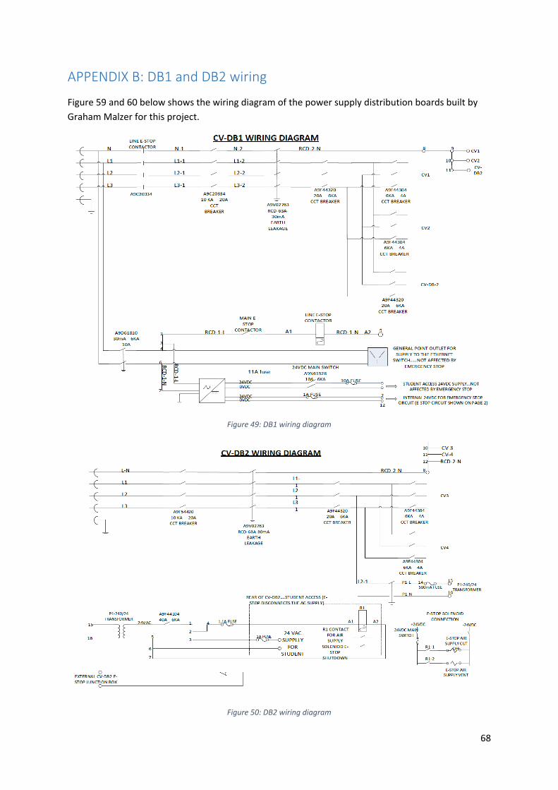
68
APPENDIX B: DB1 and DB2 wiring
Figure 59 and 60 below shows the wiring diagram of the power supply distribution boards built by
Graham Malzer for this project.
Figure 49: DB1 wiring diagram
Figure 50: DB2 wiring diagram

69
APPENDIX C: Sub state machine diagrams
The state machine diagrams of the LabVIEW program developed for this project are given in this
appendix.
Figure 51: Initialise sub state machine diagram
Figure 52: Simple transfer sub state machine diagram

70
Figure 53: Sorting sub state machine diagram
Figure 54: Scatter sub state machine diagram

71
ABBREVIATIONS AND MEANINGS
R ‐‐‐‐‐‐ RIGHT
L ‐‐‐‐‐‐ LEFT
U ‐‐‐‐‐‐ UP
G ‐‐‐‐‐‐‐ GRIP
D ‐‐‐‐‐‐ DOWN
BXS ‐‐‐‐‐‐‐ BOX SENSOR
RLS ‐‐‐‐‐‐‐ RIGHT LIMIT SWITCH
ULS ‐‐‐‐‐‐‐ UP LIMIT SWITCH
MLS ‐‐‐‐‐‐‐ MIDDLE LIMIT SWITCH
LLS ‐‐‐‐‐‐‐ LEFT LIMIT SWITCH
MBXS ‐‐‐‐‐‐ MIDDLE BOX SENSOR
CS ‐‐‐‐‐‐‐ COLOUR SENSOR
VH ‐‐‐‐‐‐‐ VARIABLE H
VA ‐‐‐‐‐‐‐ VARIABLE A
VB ‐‐‐‐‐‐‐ VARIABLE B
S ‐‐‐‐‐‐‐ STATE

72
APPENDIX D: Start‐up guide
The steps listed in this appendix should be followed in order to successfully run the conveyor
system. It is advisable to read all the steps before attempting to operate the system.
1. Turn on the air supply
2. Turn on three‐phase wall supply
3. Turn on conveyor three‐phase supplies on DB1 and DB2 and the network switch supply on
DB1
4. Switch on the AC and DC supply main switch in the control station

73
5. Open program project file (LabVIEW 32 bit)
6. Open ‘’this is the program to run’’ in list of project file programs

74
7. Run the program.
Note: you might have to let it run for a couple of seconds because of the ADAM modules on
the sorter. This way, the program can clear the initial errors generated by the modules
before communication can successfully be established with the modules. Once you hear the
sound of the vacuum pump, it means the computer is now communicating with the modules
and you can move on to the next step. Another way of doing this is to continuously start and
stop the program till the vacuum pump sound comes on.
8. Start system using start button on front panel of program or control unit
9. Make sure the Emergency stop switches are not activated
10. Always start and stop the program after the stop button on the control station has been
used to stop the system. Also, if the program is stuck in a case, just stop the program and
start it again. Use the stop button on the program front panel and not the main LabVIEW
stop program red button. The arrow in the figure below shows the stop button to use. If the
program is stopped with the stop button below, the program run has to be clicked twice
before the program starts again. Also, the stop button shown below is a latch switch.

75
APPENDIX E: Video Link
The video shown in the link posted below shows the sorting of the boxes according to their colours.
The scattering sequence was not included in the video.
https://youtu.be/h‐MOcDMnNhg