Embed Size (px)
Citation preview

IEEE TRANSACTIONS ON ELECTROMAGNETIC COMPATIBILITY, VOL. 56, NO. 1, FEBRUARY 2014 23
Design and Implementation of a TEM Striplinefor EMC Testing
Sezgin Hilavin and Alp Kustepeli
Abstract—In this paper, a stripline for radiated field immunitytesting of audio/video products is designed, constructed, calibrated,and verified. Since the canonical one is only suitable for testingequipments with height less than 70 cm, there is a need of a newdevice which is also in compliance with EN 55020 standard fortesting new large sets, like 47′′ thin-film transistor liquid crys-tal display (TFT LCD) television sets, in the frequency range of150 kHz–150 MHz. Increasing the height and width of testing areacauses important problems in terms of field uniformity regardingthe higher order modes, characteristic impedance, and reflectionsin addition to the room resonances and field interference sourceslike corners at the edges of stripline. Comprehensive numericalstudy is performed to overcome these problems and obtain the op-timum design before the construction. Measured data show thatthe new stripline is in very good agreement with the specificationsdetermined by the standards and therefore it can be used for theelectromagnetic compatibility (EMC) testing.
Index Terms—Electromagnetic compatibility (EMC), immunity,susceptibility, stripline, EN 55020, EN 61000-4–20.
I. INTRODUCTION
EACH electrical product must have an adequate level ofimmunity to the electromagnetic disturbances in its en-
vironment. Even though different tests can be employed forvalidation, they must be conducted according to some specificstandards to be in compliance with the electromagnetic compat-ibility (EMC) directive. Ideally, every product should be testedin planar electric fields which are uniform in both phase andamplitude. If the field is not uniform enough in the frequencyrange of operation, the test results highly deviate from test totest.
The stripline method is one of the most important proceduresused in EMC tests. Roseberry and Schulz investigated its use inradio frequency (RF) susceptibility tests [1]. As shown in Fig. 1,a stripline consists of two parallel conducting plates in which theequipment under test (EUT) is placed. They showed that it gen-erates uniform fields over RF spectrum and allows one to knowthe magnitude of test field more accurately than if an antenna
Manuscript received April 1, 2013; accepted June 4, 2013. Date of publica-tion July 26, 2013; date of current version January 27, 2014. This work wassupported by Vestel Electronics.
S. Hilavin was with the Department of Electrical and Electronics Engineer-ing, Izmir Institute of Technology, Izmir 35430, Turkey. He is now with VestelElectronics, Manisa 45030, Turkey (e-mail: [email protected]).
A. Kustepeli is with the Department of Electrical and Electronics Engineer-ing, Izmir Institute of Technology, Izmir 35430, Turkey (e-mail: [email protected]).
Digital Object Identifier 10.1109/TEMC.2013.2271834
Fig. 1. Basic configuration for an open stripline with source and terminatingimpedance.
were used as a field source in an anechoic chamber. Moreover,stripline requires less power when compared with the chamberbecause the electric field is concentrated mostly between theplates and it can be placed in a simple shielded room, whichmeans there is no need for an expensive anechoic chamber. Thehigh precision and repeatability of tests are the other advantagesof stripline method. Actually, a stripline can be considered asan open or nonshielded version of a transverse electromagnetic(TEM) cell, which was first described by Crawford in 1974 [2].TEM cells are frequently used for immunity measurements andthere are even some specific studies to determine the emissionlevels of integrated circuits by using them [3], [4]. Since striplineis a special type of TEM cell, it is exactly used in the same man-ner and has most of the same limitations [5]–[9]. The field ina stripline can be disturbed because of the higher order modes,reflections, and room resonances. Even though they cannot beeliminated completely, suppression to an accaptable degree canbe achieved by placing absorbing materials in and around thestripline [10]. The stripline method is preferred and widely usedin many industrial areas for EMC tests because of its advantageswhen compared with anechoic chambers.
The canonical stripline recommended by EN 55020 [11] has80 cm space between parallel conductors allowing for the test ofequipments with height less than 70 cm which is not enough totest new large products. For example, a 47′′ thin-film transistorliquid crystal display television (TFT LCD TV) set is about 1 mhigh and cannot be tested in available commercial striplines.Obtaining a stripline with a large usable area is not possible byjust scaling the EN 55020 stripline. The problem is that the fielduniformity cannot be created in the testing volume especiallydue to the first transverse electric (TE) mode in the test frequencyrange. It is acceptable to use another TEM device according toEN 55020 if the test results obtained from the two do not differby more than 2 dB for the same EUT. Therefore, in this study,it is intended to design, construct, calibrate, and verify a newstripline which is in compliance with the required specificationsand suitable for the EMC tests of large products.
0018-9375 © 2013 IEEE. Personal use is permitted, but republication/redistribution requires IEEE permission.See http://www.ieee.org/publications standards/publications/rights/index.html for more information.

24 IEEE TRANSACTIONS ON ELECTROMAGNETIC COMPATIBILITY, VOL. 56, NO. 1, FEBRUARY 2014
II. DESIGN AND CONSTRUCTION
In a stripline, in addition to the TEM mode, TE and transversemagnetic (TM) modes also propagate with the cutoff frequen-cies roughly determined by the cross section of stripline. Oneof the effects disturbing the field uniformity in stripline is theexistence of higher order modes, especially the first TE mode,and these undesired modes become an important problem whenthey are supported by the line if any one of the cross-sectionaldimensions exceeds a half wavelength [12]. For this reason, itis aimed to generate only TEM mode through the line in theapplication of the stripline method. The cutoff frequency of thefirst TE mode, the most effective and dominant mode in termsof field uniformity because the cutoff frequencies of the othersare much higher, is approximately given by [13]
fc =300√
εr (2w + 0.8h)(1)
where w is the width of the upper conductor, h is the distancebetween the upper and lower conductors, and εr is the relativedielectric constant of the substrate used between the conductors.In (1), w and h are both in meters and fc is in megahertz. Ifthe equation is examined, one can see that the certain frequencyrange of operation is primarily determined by the dimensions,and they are chosen so that the first cutoff frequency is abovethe maximum test frequency. Since w = 0.6 m and h = 0.8 mfor the standard stripline recommended by EN 55020, its firstcutoff frequency is obtained as 163 MHz which is out of thetest frequency range. But if the height is increased, the cutofffrequencies of the modes are decreased, particularly that of thefirst and most important one has to be in the considered range.The characteristic impedance of stripline, Z0 , is also determinedby the dimensions and it is given as [14]
Z0 =60√εe
ln(
8h
w+
w
4h
)for w/h ≤ 1 (2)
where εe is the effective dielectric constant which is given by
εe =εr + 1
2+
εr − 12
√1 + 12 h/w
. (3)
Since the stripline is placed in air, εr = 1, and εe is obtained as 1by using (3). In this case, if the stripline is designed as its charac-teristic impedance to be 50 Ω, it results in a narrow width or lowheight and it would not provide necessary testing volume [5].Therefore, even for the standard stripline, Z0 cannot be chosenas 50 Ω. For the dimensions used for the standard stripline, thecharacteristic impedance of the line is obtained as 143 Ω. How-ever, the internal impedance of the signal source is 50 Ω, anda matching network is used to decrease the mismatch betweenthe source and the line [11]. The characteristic impedance de-termines the voltage across the plates for a given input powerand hence the electric field intensity inside the stripline, whichis obtained by the ratio of the plate voltage to the plate sepa-ration [15]. EN 55020 describes the setup, shown in Fig. 2, toestablish a specific electric field at the center of the test volume.The matching network at the feed point and the termination atthe end of the line reduces the mismatch level [12], [15]. Theinduced voltage at the measuring plate is measured with an RF
Fig. 2. Circuit arrangement for the calibration of the system.
Fig. 3. Fringing fields at the edges of a two-plate open stripline for twodifferent applications.
millivoltmeter and the field intensity in the stripline is 3 V/mif the measured plate voltage is within the limits given by thestandard. The test is performed for the whole test frequencyrange and deviations more than ±2 dB in the calibration curveare taken into account by the correction factor
K1 =Um
Un(4)
where Um is the measured voltage value at the measuring plateand Un is the nominal voltage value.
The widths of plates are also important for the field unifor-mity. Two plate striplines can have equal plate widths or havethe lower one wider than the top one as illustrated in Fig. 3. Ifthe widths are equal, there are bowings at the edges of the platesand this prevents the field concentration inside the stripline. Ifthe lower plate is wider than the upper one, the fringing fields aremore perpendicular to the lower one and they increase the uni-formity [12]. This special feature which is used in the standardstripline is also employed in the design of new stripline. Theuniform area is described by the standard EN 61000-4-20 [16]and it is the volume between the two virtual vertical planes,which are orthogonal to the propagation direction of the field,as shown with the points in Fig. 4. The planes are 0.5 m awayfrom the center of the stripline. This length was suitable to keepthe TV in usable test volume which is the uniform area betweenthese planes. Six points with 0.5 m distance between them wereselected on both planes as shown in the figure. Two points werein horizontal and three points are in vertical orientation. Theevaluation of the uniformity is made by checking the powerrequired to create the same field level at each point. Then, themaximum power difference between the points in each plane is

HILAVIN AND KUSTEPELI: DESIGN AND IMPLEMENTATION OF A TEM STRIPLINE FOR EMC TESTING 25
Fig. 4. Measurement points in plane 1 and in plane 2 for the uniformity test.(a) Side view. (b) Cross-sectional view.
found for the whole test frequency range. According to the 6 dBcriterion, maximum difference at each frequency must be lessthan 6 dB for at least 75% points. Since there are six points ineach plane, maximum difference of five points must be less than6 dB for each plane.
There are also other important problems caused by the ter-mination, tapered sections and feed point. A 150 Ω terminationresistor is used to decrease the reflections at the end of the stan-dard stripline. Due to the tapered sections, the wave launched atthe feed exhibits a spherical wavefront and results in consider-able variation in phase across the width of the line, particularlyat the transition between the tapered section and the beginning ofparallel plate region, and field interference can also be generatedat the edges of these transitions [12]. In addition to these, thereare resonances caused by the stripline itself or the room in whichit is placed. To obtain a uniform field even inside the standardstripline, they are suppressed by using absorbing material in andaround the stripline. All of the problems mentioned previouslyare determinant on the operating frequency range and the fielduniformity; therefore, they must be taken into consideration andovercome in the design of stripline carefully.
According to the information given previously, one can con-clude that the dimensions w and h of stripline are two parametersto be adjusted and optimized in accordance with design needs.In order to test large TFT LCD products up to 47′′ which areabout 1 m high, the plates of the stripline should be at least 1.2 mapart for a suitable usable area. For this reason, the height ofthe stripline h was chosen as 1.2 m. The reason for not increas-ing the height, more than a suitable one, is that more power isneeded to obtain the same electric field intensity in the line anda smaller width is obtained for the same cutoff frequency. If onecalculates the width of the line such that the cutoff frequencyof the first mode to be 150 MHz with the height specified, itis found that w = 0.52 m which is even smaller than the widthof the standard line and is not suitable for the tests of largeproducts. Furthermore, the characteristic impedance of the lineis obtained as 175 Ω which increases the mismatch at bothends of line because special RF power resistors are used forthe termination, which is 150 Ω, and for the matching network,which matches 150 to 50 Ω, in order to get sufficient flat RFresponses in the testing frequency range. If the width of thestandard line, w = 0.6 m, is used for the new one, the cutofffrequency of the first mode is obtained as 139 MHz from (1).
Fig. 5. Block diagram of the stripline testing system.
It seems that it might be suitable in terms of obtaining a TEMfield since that value is very close to the end of the frequencyrange of operation but one must also consider the characteristicimpedance which is obtained as 167 Ω. Even though it is seenthat all of these dimensions and values are not appropriate forthe optimum design, they were taken into consideration at thebeginning of the design process. Simulations were performedby using EMCOS software package [17]. It was seen in thepreliminary numerical study that it was better to decrease thereflections at the end of the line. Therefore, it was concluded anddecided to choose the characteristic impedance of the line as tobe 150 Ω. Accordingly the width is obtained about 0.8 m and thecutoff frequency of the larger stripline is about 117 MHz withthe new dimensions, w = 0.8 m and h = 1.2 m. This means thatTE and TM waves exist after 117 MHz. In fact, there is no pos-sible solution to remove the modes from the testing frequencyrange completely. However, their effects on the field uniformitycould be slightly suppressed. Reducing their impact on the fielduniformity by using some absorbers is a helpful solution [18].If enough attenuation can be obtained inside the stripline, thenthe field uniformity conditions accepted by the standard couldbe fulfilled.
The characteristic impedance of the line is different from thesource impedance and a matching network is used at the sourceside. The matching network and circuit equivalent of the wholesystem are given in Fig. 5. The widths of upper and lower platesare also chosen differently and the lower plate’s width was de-termined as 1.1 m from the simulations. In view of the fact thatthe discontinuity parts disturb the field uniformity, the taperedparts must be far from the testing volume and the length of theline is taken as 2.4 m. After the dimensions and characteristicimpedance were determined, simulations were again performedto improve the performance of the stripline by making the otheradjustments before realizing it. The design was obviously ex-amined according to EN 55020, EN 61000-4-20, and voltagestanding wave ratio (VSWR) by using the configurations givenin Figs. 2 and 4. All of the simulations were performed exactlyin the same manner as to be done in the measurements. In orderto find the field strength in the test volume, a field probe wasinserted and the plate voltage was computed via a voltage probein the simulation. It was seen that there were some resonancesaround 100–120 MHz as expected and the extension of usefulfrequency range was achieved by absorber loading. Many dif-ferent dimensions and placements of the absorbers were appliedin the simulations to optimize the configuration by consideringtheir electrical properties [19]. The simulations showed that thedielectric properties of the absorbers highly affected the results
26 IEEE TRANSACTIONS ON ELECTROMAGNETIC COMPATIBILITY, VOL. 56, NO. 1, FEBRUARY 2014
Fig. 6. Plate voltage for the stripline.
as well as their shapes and locations. Based on the simulation tri-als, 20 cm pyramidal absorbers were used, and they were placedaround the open sides and at the tapered sections. However,resonances still existed about 110 MHz similar to the simula-tion results. This problem was solved by using hybrid absorberswhich are made of ferrite tiles and RF pyramidal absorbers to-gether to strengthen the attenuation performance. They improvethe uniformity of the field inside by increasing the vertical com-ponent of the electrical field at the edges of the line [20]. Finally,the stripline was constructed with the dimensions and the specialarrangements of the absorbers according to the results obtainedfrom the detailed numerical study.
III. CALIBRATION AND VERIFICATION
After the construction, the calibration of the new stripline wasmade as specified by the standard EN 55020. An electric fieldprobe was placed at the centre of the line. The input voltage waschanged until 3 V/m electrical field strength was obtained at15 MHz. By using an RF amplifier the power was kept constantin the whole test frequency range and an RF millivoltmeter wasplaced in the center of the measuring plate to get the calibra-tion voltage. The calibration curve is given in Fig. 6 togetherwith the limits of the standard. The computed results are alsopresented in the figure. Even though the measured plate voltageis out of the limits for only a few frequencies at the very endof the test frequency range, the correction factor K1 is used atthese frequencies for the tests of products. The measured fielduniformity test results for both planes are presented in Fig. 7.One can see that the power difference at each frequency is in the6 dB tolerance range for both 5 points and 6 points. Therefore,the criterion is actually satisfied for 100% of the points in thetest planes, which is a very satisfactory result in terms of thefield uniformity.
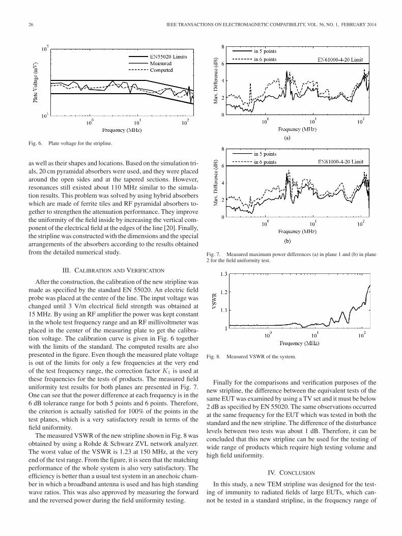
The measured VSWR of the new stripline shown in Fig. 8 wasobtained by using a Rohde & Schwarz ZVL network analyzer.The worst value of the VSWR is 1.23 at 150 MHz, at the veryend of the test range. From the figure, it is seen that the matchingperformance of the whole system is also very satisfactory. Theefficiency is better than a usual test system in an anechoic cham-ber in which a broadband antenna is used and has high standingwave ratios. This was also approved by measuring the forwardand the reversed power during the field uniformity testing.
Fig. 7. Measured maximum power differences (a) in plane 1 and (b) in plane2 for the field uniformity test.
Fig. 8. Measured VSWR of the system.
Finally for the comparisons and verification purposes of thenew stripline, the difference between the equivalent tests of thesame EUT was examined by using a TV set and it must be below2 dB as specified by EN 55020. The same observations occurredat the same frequency for the EUT which was tested in both thestandard and the new stripline. The difference of the disturbancelevels between two tests was about 1 dB. Therefore, it can beconcluded that this new stripline can be used for the testing ofwide range of products which require high testing volume andhigh field uniformity.
IV. CONCLUSION
In this study, a new TEM stripline was designed for the test-ing of immunity to radiated fields of large EUTs, which can-not be tested in a standard stripline, in the frequency range of

HILAVIN AND KUSTEPELI: DESIGN AND IMPLEMENTATION OF A TEM STRIPLINE FOR EMC TESTING 27
150 KHz–150 MHz. A simulation program was used for thedetailed numerical study to optimize the stripline in terms ofthe standards, EN 55020 and EN 61000-4-20, and the VSWRbefore the realization. After the construction, it was seen thatthe performance of the new stripline was very satisfactory andthe correction factor K1 needed to be used at only a few fre-quencies. The most important and challenging part of the designwas to obtain the field uniformity in the stripline because it wasnot possible to move the first TE mode outside of the usable fre-quency range due to the large dimensions. Its disturbing effectwas suppressed by using absorbers with special placements. Theverifications and comparisons were also made according to thecriterion specified by the standard. From the measurement re-sults it is seen that the new TEM stripline is in compliance withrequirements specified by the standards, especially in terms ofthe field uniformity, and therefore it can be used as a compatibletest site for immunity to radiated fields.
ACKNOWLEDGMENT
The authors would like to thank Vestel Electronics for theusage of their R&D laboratory facilities during this research.
REFERENCES
[1] B. E. Roseberry and R. B. Schulz, “A parallel-stripline for testing of RFsusceptibility,” IEEE Trans. Electromagn. Compat., vol. 7, no. 2, pp. 142–150, Jun. 1965.
[2] M. L. Crawford, “Generation of standard EM fields using TEM trans-mission cells,” IEEE Trans. Electromagn. Compat., vol. EMC-16, no. 4,pp. 189–195, Nov. 1974.
[3] S. Deng, T. Hubing, and D. G. Beetner, “Characterizing the electricfield coupling from IC heatsink structures to external cables using TEMcell measurements,” IEEE Trans. Electromagn. Compat., vol. 49, no. 4,pp. 785–791, Nov. 2007.
[4] F. Fiori and F. Musolini, “Measurement of integrated circuit conductedemissions by using a transverse electromagnetic mode (TEM) cell,” IEEETrans. Electromagn. Compat., vol. 43, no. 4, pp. 622–628, Nov. 2001.
[5] Y. C. Chung, T. W. Kang, and D. C. Park, “Design and construction ofstripline for measuring electromagnetic immunity of vehicular electricalcables,” in Proc. Electromagn. Compat. Int. Symp., 1997, pp. 9–12, paper:10.1109/ELMAGC.1997.617042, 1997.
[6] Z. Jingjun and F. Junmei, “Higher order mode cutoff frequencies in TEMcells calculated with TLM method,” IEEE Trans. Electromagn. Compat.,vol. 30, no. 4, p. 563—566, Nov. 1988.
[7] P. F. Wilson and M. T. Ma, “Simple approximate expressions for higherorder mode cutoff and resonant frequencies in TEM cells,” IEEE Trans.Electromagn. Compat., vol. 28, no. 3, pp. 125–130, Aug. 1986.
[8] J. Kuveda and R. K. Libla, “Determination of frequency range limit whenusing stripline as emission or immunity test methods,” in Proc. IEEE Int.Symp. Electromagn. Compat., Aug. 2006, vol. 3, pp. 823–828.
[9] R. Lampe, P. Klock, D. Tanner, and P. Mayes, “Analysis and experimentconcerning the cutoff frequencies of rectangular striplines,” IEEE Trans.Microw. Theory Tech., vol. MTT-34, no. 8, pp. 898–899, Aug. 1986.
[10] M. Valek, T. Korinek, and T. Bostik, “Design of stripline for EMC testing,”in Proc. 14th IEEE Conf. Microw. Tech., 2008, pp. 1–4.
[11] Sound and Television Broadcast Receivers and Associated Equipment—Immunity Characteristics—Limits and Methods of Measurement Specifi-cation, CENELEC Standard EN 55020, 2007.
[12] ETSI Technical Committee Electromagnetic compatibility and Radiospectrum Matters, “Improvement on radiated methods of measurement(using test site) and evaluation of the corresponding measurement uncer-tainties; part 5: striplines,” ETSI, France, Tech. Rep. TR 102 273-5 V1.2.1,2001-12.
[13] M. Golio and B. Raton, The RF and Microwave Handbook. Baco Raton,FL, USA: CRC Press, 2001.
[14] D. M. Pozar, Microwave Engineering, 2nd ed. New York, NY, USA:Wiley, 1998.
[15] D. Morgan, A Handbook for EMC Testing and Measurement, 1st ed.Milton Keynes, U. K.: The Institution of Engineering and Technology,1994.
[16] Electromagnetic Compatibility (Emc) – Part 4–20: Testing and Measure-ment Techniques – Emission and Immunity Testing in Transverse Electro-magnetic (Tem) Waveguides, CENELEC Standard EN 61000–4–20, 2010.
[17] EMC studio electromagnetic simulation software, ver.6.0.1, EMCOS,Tbilisi, Georgia, 2010.
[18] W. Bittinger, “Properties of open strip lines for EMC measurements,” inProc. IEEE Int. Symp. Electromagn. Compat., Dallas, TX, USA, Aug.9–13, 1993, pp. 120–125.
[19] K. Shimada, T. Hayashi, and M. Tokuda, “Fully compact anechoic cham-ber using the pyramidal ferrite absorber for immunity test,” in Proc. IEEEInt. Symp. Electromagn. Compat., 2000, vol. 1, pp. 225–230.
[20] K. Malaric and J. Bartolic, “Design of a TEM-cell with increased usabletest area,” Turkish J. Elect. Eng. Comput. Sci., vol. 11, no. 3, pp. 143–154,2003.
Authors’ photographs and biographies not available at the time of publication.