Embed Size (px)
Citation preview
STRIPLINE BPM WITH INTEGRAL IN-VACUO TERMINATION
A. Stella, A. Ghigo, V. Lollo, F. Marcellini, M. Serio, INFN – LNF, Frascati, Italy
Abstract We report the design and realization of the stripline
type beam position monitor to be used in the SPARC-
LAB transfer lines. While the directional properties
provided by matched termination at the downstream end
are not strictly required in a transfer line, yet matched
loads at the end of the stripline electrodes are preferable
to reduce the loss factor and to avoid unwanted reflection
to the detection electronic. The integration of a matched
resistive load inside the vacuum chamber allows halving
the number of UHV feedthroughs.
INTRODUCTION
In the framework of the SPARC-LAB activities [1] a
large number of beam position monitors (BPM) is
foreseen for installation along the photoinjector transfer
lines, to measure the transverse beam position with a
resolution of ~10 µm rms in a range of charge between
0.01 nC and 1 nC.
The pickup selected for use is generally referred to as
stripline and is composed of four stainless steel electrodes
of length l and width w, mounted with a π/2 rotational
symmetry at a distance d from the vacuum chamber, to
form a transmission line of characteristic impedance Zo
with the beam pipe (Fig. 1).
Figure 1: Longitudinal and transverse pickup sections.
PICKUP DESIGN
The strips have angular width of ~40 degrees and a
length of 146 mm (Tab. 1), transverse dimensions have
been chosen to form with the vacuum pipe a transmission
line with characteristic impedance Z0=50 Ω.
Time domain reflectometry measurements have been
performed to select the final strip width to get the best
impedance matching.
Table 1: Summary of Stripline BPM Parameters
Value Unit
Char. impedance Zo 50 Ohm
Strips distance d 4 mm
Strips width w 14.3 mm
Strips thickness t 1 mm
Strip length l 146 mm
Bandwidth 1st lobe 1.1 GHz
Vacuum chamber radius R 22 mm
Zb @ 500MHz 6.5 Ohm
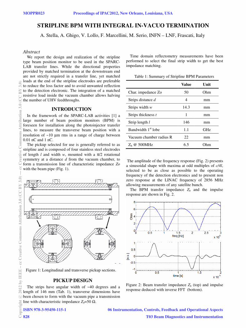
The amplitude of the frequency response (Fig. 2) presents
a sinusoidal shape with maxima at odd multiples of c/4l,
selected to be as close as possible to the operating
frequency of the detection electronics and to present non
zero response at the LINAC frequency of 2856 MHz
allowing measurements of any satellite bunch.
The BPM transfer impedance Zb and the impulse
response are shown in Fig. 2.
Figure 2: Beam transfer impedance Zb (top) and impulse
response deduced with inverse FFT (bottom).
MOPPR023 Proceedings of IPAC2012, New Orleans, Louisiana, USA
ISBN 978-3-95450-115-1
828Cop
yrig
htc
2012
byIE
EE
–cc
Cre
ativ
eC
omm
onsA
ttri
butio
n3.
0(C
CB
Y3.
0)—
ccC
reat
ive
Com
mon
sAtt
ribu
tion
3.0
(CC
BY
3.0)
06 Instrumentation, Controls, Feedback and Operational Aspects
T03 Beam Diagnostics and Instrumentation
STRIPLINE TERMINATION The output signal is coupled to the detection electronics
through an SMA female pin vacuum feedthrough while the other end of each stripline can be alternatively terminated in open, short or matched impedance.
Matched loads at the end of the stripline electrodes have been preferred to reduce the loss factor and to avoid unwanted reflection to the detection electronic.
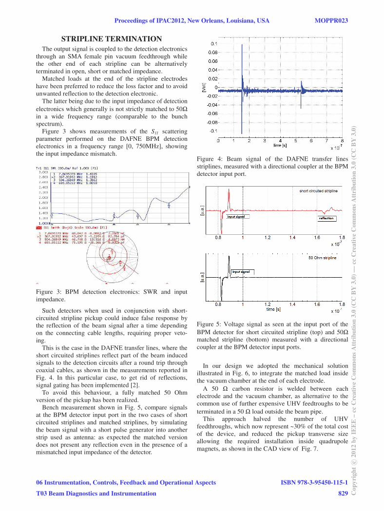
The latter being due to the input impedance of detection electronics which generally is not strictly matched to 50Ω in a wide frequency range (comparable to the bunch spectrum).
Figure 3 shows measurements of the S11 scattering parameter performed on the DAFNE BPM detection electronics in a frequency range [0, 750MHz], showing the input impedance mismatch.
Figure 3: BPM detection electronics: SWR and input impedance.
Such detectors when used in conjunction with short-circuited stripline pickup could induce false response by the reflection of the beam signal after a time depending on the connecting cable lengths, requiring proper veto-ing.
This is the case in the DAFNE transfer lines, where the short circuited striplines reflect part of the beam induced signals to the detection circuits after a round trip through coaxial cables, as shown in the measurements reported in Fig. 4. In this particular case, to get rid of reflections, signal gating has been implemented [2].
To avoid this behaviour, a fully matched 50 Ohm version of the pickup has been realized.
Bench measurement shown in Fig. 5, compare signals at the BPM detector input port in the two cases of short circuited striplines and matched striplines, by simulating the beam signal with a short pulse generator into another strip used as antenna: as expected the matched version does not present any reflection even in the presence of a mismatched input impedance of the detector.
Figure 4: Beam signal of the DAFNE transfer lines striplines, measured with a directional coupler at the BPM detector input port.
Figure 5: Voltage signal as seen at the input port of the BPM detector for short circuited stripline (top) and 50Ω matched stripline (bottom) measured with a directional coupler at the BPM detector input ports.
In our design we adopted the mechanical solution
illustrated in Fig. 6, to integrate the matched load inside the vacuum chamber at the end of each electrode.
A 50 Ω carbon resistor is welded between each electrode and the vacuum chamber, as alternative to the common use of further expensive UHV feedtroughs to be terminated in a 50 Ω load outside the beam pipe.
This approach halved the number of UHV feedthroughs, which now represent ~30% of the total cost of the device, and reduced the pickup transverse size allowing the required installation inside quadrupole magnets, as shown in the CAD view of Fig. 7.
Proceedings of IPAC2012, New Orleans, Louisiana, USA MOPPR023
06 Instrumentation, Controls, Feedback and Operational Aspects
T03 Beam Diagnostics and Instrumentation
ISBN 978-3-95450-115-1
829 Cop
yrig
htc
2012
byIE
EE
–cc
Cre
ativ
eC
omm
onsA
ttri
butio
n3.
0(C
CB
Y3.
0)—
ccC
reat
ive
Com
mon
sAtt
ribu
tion
3.0
(CC
BY
3.0)
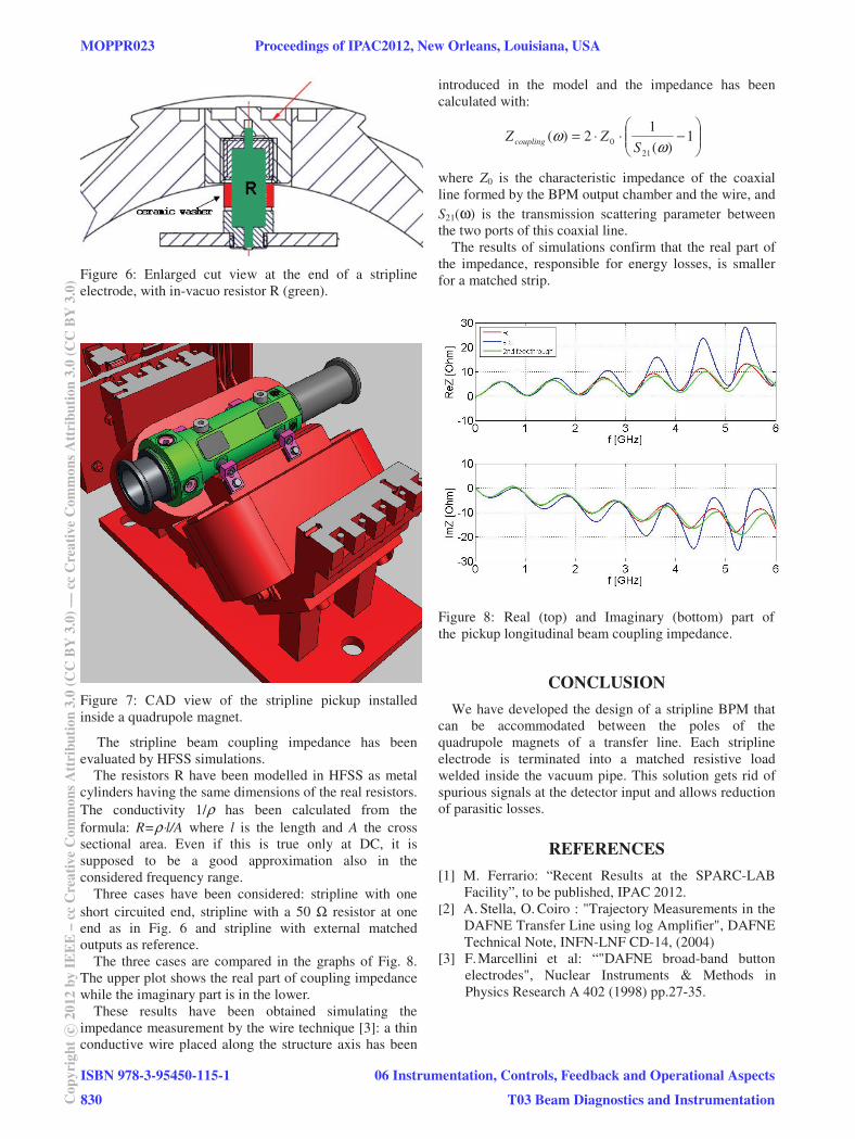
Figure 6: Enlarged cut view at the end of a stripline electrode, with in-vacuo resistor R (green).
Figure 7: CAD view of the stripline pickup installed inside a quadrupole magnet.
The stripline beam coupling impedance has been evaluated by HFSS simulations.
The resistors R have been modelled in HFSS as metal cylinders having the same dimensions of the real resistors. The conductivity 1/ρ has been calculated from the formula: R=ρ⋅l/A where l is the length and A the cross sectional area. Even if this is true only at DC, it is supposed to be a good approximation also in the considered frequency range.
Three cases have been considered: stripline with one short circuited end, stripline with a 50 Ω resistor at one end as in Fig. 6 and stripline with external matched outputs as reference.
The three cases are compared in the graphs of Fig. 8. The upper plot shows the real part of coupling impedance while the imaginary part is in the lower.
These results have been obtained simulating the impedance measurement by the wire technique [3]: a thin conductive wire placed along the structure axis has been
introduced in the model and the impedance has been calculated with:
−⋅⋅= 1)(
12)(
210
ωω
SZZcoupling
where Z0 is the characteristic impedance of the coaxial line formed by the BPM output chamber and the wire, and S21(ω) is the transmission scattering parameter between the two ports of this coaxial line.
The results of simulations confirm that the real part of the impedance, responsible for energy losses, is smaller for a matched strip.
Figure 8: Real (top) and Imaginary (bottom) part of the pickup longitudinal beam coupling impedance.
CONCLUSION
We have developed the design of a stripline BPM that can be accommodated between the poles of the quadrupole magnets of a transfer line. Each stripline electrode is terminated into a matched resistive load welded inside the vacuum pipe. This solution gets rid of spurious signals at the detector input and allows reduction of parasitic losses.
REFERENCES
[1] M. Ferrario: “Recent Results at the SPARC-LAB Facility”, to be published, IPAC 2012.
[2] A. Stella, O. Coiro : "Trajectory Measurements in the DAFNE Transfer Line using log Amplifier", DAFNE Technical Note, INFN-LNF CD-14, (2004)
[3] F.Marcellini et al: “"DAFNE broad-band button electrodes", Nuclear Instruments & Methods in Physics Research A 402 (1998) pp.27-35.
MOPPR023 Proceedings of IPAC2012, New Orleans, Louisiana, USA
ISBN 978-3-95450-115-1
830Cop
yrig
htc
2012
byIE
EE
–cc
Cre
ativ
eC
omm
onsA
ttri
butio
n3.
0(C
CB
Y3.
0)—
ccC
reat
ive
Com
mon
sAtt
ribu
tion
3.0
(CC
BY
3.0)
06 Instrumentation, Controls, Feedback and Operational Aspects
T03 Beam Diagnostics and Instrumentation