Embed Size (px)
Citation preview
19
Journal of Mechanical Engineering
ISSN 1823-5514© 2012 Faculty of Mechanical Engineering, Universiti Teknologi MARA (UiTM), Malaysia.
Vol. 9, No. 1, 19-44, 2012
Design and Flight Analysis of the Kenyalang-1 Fuel Cell Powered
Unmanned Aircraft
Thomas A. Ward1 Faculty of Mechanical Engineering
Universiti Teknologi MARA (UiTM), Shah Alam email:[email protected]
ABSTRACT
The Kenyalang-12 is an unmanned technology demonstrator aircraft equipped with a hydrogen fuel cell to provide power for its electric propulsion system. This aircraft was designed, built, and flight-tested at the Universiti Teknologi MARA Flight Technology and Test Center located in Shah Alam, Malaysia. It is the first of its kind entirely designed, built, and test flown in Southeast Asia. The fuel cell is capable of providing 500 W of continuous power, fed by hydrogen gas that is stored in a pressurized tank. The only exhaust product of this power system is water vapor, making it environmentally clean. Since fuel cells are solid state devices that generate power using electrochemical (non-combustion) processes, the power system is mechanically reliable, quiet, and generates much less heat than conventional combustion engines. Two types of power systems were flight-tested: Type A (consisting only of the fuel cell) and Type B (a pseudo-hybrid design that added a two-cell lithium polymer battery in series to augment the fuel cell). Flight telemetry of the aircraft configured with each of the two power systems provides a design and performance baseline for a future generation of fuel cell powered aircraft.
Introduction
Over the last thirty years, unmanned air vehicles (UAVs) have proved themselves as reliable assets in accomplishing remote sensing, military reconnaissance, and telecommunication missions. Since their inception, the dominate type of propulsion system used on commercial UAVs have been combustion engines that use hydrocarbon fuels. The rising cost of hydrocarbon fuels and fears about the
2 JM V9(1).indd 19 7/24/2012 2:04:52 PM
20
Journal of Mechanical Engineering
harmful health and environmental effects of combustion engine emissions have intensified a global demand to transition to alternative “green” power sources. Also many nations are eager to become independent of foreign oil suppliers due to economic and security concerns. For these reasons, there is great interest in fuel cells as an alternative energy source.
Unlike a combustion engine, a fuel cell does not use chemical combustion of fuel to release heat. A fuel cell transforms the chemical energy stored in a fuel into direct-current (DC) electricity by breaking molecular bonds. It does this in a single step without the need for moving parts (solid state). Polymer electrolyte membrane fuels cells (PEMFC) powered by compressed hydrogen gas are attractive for long-endurance UAVs because of their high efficiency and high specific energy. PEMFC use a thin, proton conductive polymer membrane as an electrolyte, which is impermeable to gases but conducts protons. This membrane is squeezed between two porous electrodes, generally made of carbon cloth or paper. A thin outer layer of platinum is placed at the interface between the electrodes and the membrane to serve as a catalyst. Gaseous hydrogen is fed into the membrane where it undergoes electrochemical reactions at the anode catalyst surface, creating an oxidation process that splits the hydrogen atoms into protons and electrons. The protons conduct through the membrane, while the electrons travel through an outside circuit, constituting an electric DC current. The electrons then flow to the cathode catalyst surface (on the other side of the membrane), where they electrochemically recombine with the protons that are conducted through the membrane and oxygen (normally from air) fed into that site (reduction process). The result is the creation of water vapor as an exhaust product. Thus, if operating correctly the exhaust emissions of hydrogen PEMFC are safe for health and the environment. Also the absence of chemical combustion gives PEMFC a low thermal signature compared to internal combustion or gas turbine engines.
Modern PEMFC are also attractive as a replacement for batteries in aerospace applications because they generally have a greater gravimetric power density (power per unit mass). Although modern PEMFC still have a slightly inferior volumetric power density (power per unit volume) than batteries, they have a few other advantages. Fuel cells can be quickly recharged simply by refueling, while batteries must either be disposed or plugged into a power source to be recharged in a time consuming process. Fuel cells also allow independent scaling between power (determined by the cell size and number of cells in a stack) and capacity (fuel tank size). Fuel cells scale well for power ranging from 1 W to several megawatts, while batteries scale poorly at large sizes [1].
Fuel cells were used to generate electricity for communication, guidance, and life support in the US Gemini and Apollo Lunar Missions in the 1960s and 1970s [2]. However, despite the early use of fuel cells in space applications, fundamental research into fuel cell powered electrical propulsion systems began several decades later. The first successful flight of an unmanned air vehicle (UAV) equipped with an electric propulsion system powered by a PEMFC was
2 JM V9(1).indd 20 7/24/2012 2:04:52 PM
21
Design and Flight Analysis of the Kenyalang-1 Fuel Cell Powered
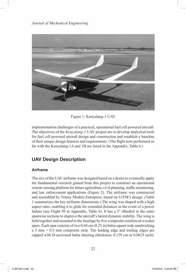
achieved by AeroVironment, Inc. in 2003, with their Hornet Micro Air Vehicle (MAV) [3]. AeroVironment expanded upon this feat in 2005 by flying their Global Observer UAV equipped with a PEMFC powered electric propulsion system. The US Naval Research Laboratory (NRL) designed and built the Spider Lion UAV, achieving a record flight endurance of three hours and nineteen minutes. [4] Lastly in 2005, university research on this topic began to appear with pioneering work by Georgia Institute of Technology (US) [5,6] and FH Wiesbaden University of Applied Sciences (Germany)3, both who independently designed and flew PEMFC powered UAV. In 2006, researchers from California State University (US) designed and flew a 650 W PEMFC UAV. [7] In 2007, California State University partnered with Oklahoma State University (US) and Temasek Polytechnic (Singapore) to design and fly the Pterosaur UAV. This UAV used a hybrid power system, consisting of a compact 150 W PEMFC and a 60 W lithium ion battery pack to break the 16-hour endurance record (125 km distance) for an electric-powered UAV [8]. The German Aerospace Center (Deutches Zentrum für Luft-und Raumfahrt or DLR) led a consortium that included the Swiss company Smartfish Gmbh, who built and flew the Hyfish UAV, using a compact 1.2 kW PEMFC [9]. AeroVironment also conducted a 5-hour record breaking flight of their commercial hand-launched Puma UAV. This flight doubled the previous endurance record for a Puma because its battery packs had been replaced by a PEMFC [10]. Subsequent flights in 2008 extended the endurance record to 7 hours. In 2008, Boeing Research and Technology Europe fitted a PEMFC in a hybrid configuration with a lithium ion battery pack onto a manned Dimono motorized glider, which they test-flew in Spain [11]. This was the first manned flight of a hybrid powered aircraft. Also Bluebird Aero Systems, Inc. developed and began marketing a commercial UAV called Boomerang, which uses a 200 W compact PEMFC4. In 2009, the Korea Advanced Institute of Science and Technology (South Korea) built and flew a micro UAV for 10-hrs using gaseous hydrogen that was generated in-flight from the hydrolysis of stored liquid sodium borohydride.5 The German Aerospace Center (DLR) flew the first manned airplane that was purely powered by a fuel cell (non-hybrid) called the Antares [12]. NRL conducted test flights of the Ion Tiger and XFC (eXperimental Fuel Cell) UAVs, setting a new endurance record with Ion Tiger with a flight time of 23 hours and 17 minutes [13]. Also in 2009, the Universiti Teknologi MARA (Malaysia) built and flew a UAV powered by a 500 W hydrogen PEMFC called Kenyalang-1 (Figure 1) [14]. In 2010, the Kenyalang-1 was modified and flown with a hybrid power system that consisted of the same PEMFC used in 2009, but serially connected with a two-cell lithium polymer battery pack (further described in this paper). Also in 2010, the National Cheng Kung University (Taiwan) flew the Gray-faced Buzzard UAV powered by a hybrid combination of a 1 kW PEMFC and lithium ion batteries [15].
Despite these initial successes in creating technology demonstrator aircraft and a few commercialized UAVs, much research is still needed to define the
2 JM V9(1).indd 21 7/24/2012 2:04:52 PM
22
Journal of Mechanical Engineering
implementation challenges of a practical, operational fuel cell powered aircraft. The objectives of the Kenyalang-1 UAV project are to develop analytical tools for fuel cell powered aircraft design and construction and establish a baseline of their unique design features and requirements. (The flight tests performed so far with the Kenyalang-1A and 1B are listed in the Appendix, Table 6.)
UAV Design Description
Airframe
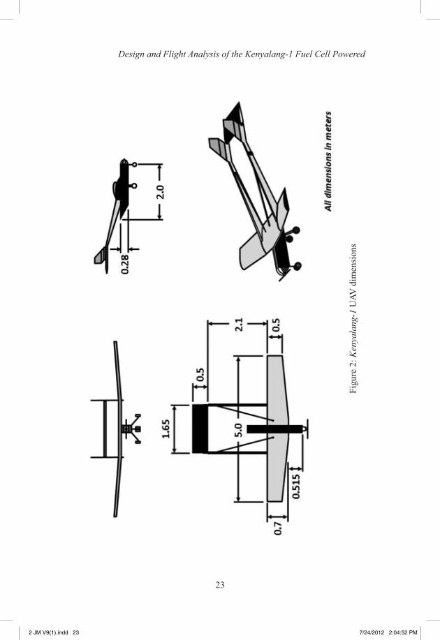
The size of the UAV airframe was designed based on a desire to eventually apply the fundamental research gained from this project to construct an operational remote sensing platform for future agriculture, civil planning, traffic monitoring, and law enforcement applications (Figure 2). The airframe was constructed and assembled by Tritiny Models Enterprise, based on UiTM’s design. (Table 1 summarizes the key airframe dimensions.) The wing was shaped with a high aspect ratio, enabling it to glide for extended distances in the event of a power failure (see Flight #9 in Appendix, Table 6). It has a 5° dihedral in the outer spanwise sections to improve the aircraft’s lateral dynamic stability. The wing is held together and mounted to the fuselage by five composite-reinforced wooden spars. Each spar consists of two 0.64 cm (0.25 in) balsa square rods sandwiching a 5 mm × 0.5 mm composite strip. The leading edge and trailing edges are capped with D-sectioned balsa sheeting (thickness: 0.159 cm or 0.0625 inch).
Figure 1: Kenyalang-1 UAV
2 JM V9(1).indd 22 7/24/2012 2:04:52 PM
23
Design and Flight Analysis of the Kenyalang-1 Fuel Cell Powered
Figu
re 2
: Ken
yala
ng-1
UAV
dim
ensi
ons
2 JM V9(1).indd 23 7/24/2012 2:04:52 PM
24
Journal of Mechanical Engineering
The wing frame is constructed of balsa wood, wrapped with a heat-shrink plastic film skin. The ailerons are hinged with a nylon rod and actuated by pushrods connected to a servo.
The horizontal tail has a straight, planar shape (no sweep angle) with a chord of 0.5 m. The entire horizontal tail acts as an all-moving elevator control surface actuated by pushrods connected to a servo. The twin vertical stabilizers are made of flat, balsa wood surfaces (no airfoil shape). Rudders are connected to each of the stabilizers and are actuated by pushrods connected to a servo. The horizontal tail and vertical stabilizers are constructed of a balsa wood frame with a plastic film skin. The control surfaces (elevator and rudders) are all hinged with a nylon rod. The entire tail section is connected to the wing (between the outer and inner-span sections) by twin tail booms. The tail booms bend upwards at 15° to allow unimpeded rotation at take-off. The bend also positions the tail and stabilizers out of the propeller slipstream. Torsion is restrained by two graphite rods connecting each of the tail booms to the center of the inner-span wing section.
The fuselage is aerodynamically shaped with an outer shell made of a single-layer of composite fiber (with resin) cloth. The shell tapers upward at the aft end to allow unimpeded rotation at take-off. It is also open at the aft end to allow flowing air from the intake (used to oxidize and cool the fuel cell) to escape. This shell encases a welded, aluminum internal frame that supports the motor, electronic speed controller (ESC), fuel cell and controller, hydrogen storage tank and feed system, avionics, and landing gear. The aft portion of the frame is bolted to the wing.
The landing gear is a tricycle arrangement. The front landing gear strut is made of a single aluminum tube (12 mm OD, 5 mm ID), which supports two adjacent 12.7 cm (5.0 in) diameter Richmodel wheels. The rear landing gear is made of aluminum, with each strut supporting the same 12.7 cm diameter Richmodel wheel.
The most challenging aspect of the airframe design was to minimize weight. The large surface areas required for the wing and horizontal tail posed a particularly great challenge. Different types of composite materials were examined, but lack of access to an autoclave ruled out the use of thermoplastic composites. As a test case, the wing and horizontal tail were initially fabricated using fiberglass with an epoxy resin. Polystyrene foam was used as a mold and inner core. However, the weight of the resulting structures proved to be too heavy. So to lighten the airframe, it was necessary to build a composite-reinforced balsa wood frame.
The largest single component of weight is the fuel cell, which is supported by the fuselage aluminum inner frame. This was placed forward of the wing, just behind the motor in order to move the center of gravity in front of the aerodynamic center of the wing. The fuel cell and all of the internal components are balanced to give a positive static margin to ensure longitudinal static stability.
2 JM V9(1).indd 24 7/24/2012 2:04:52 PM
25
Design and Flight Analysis of the Kenyalang-1 Fuel Cell Powered
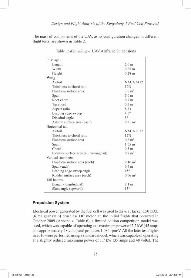
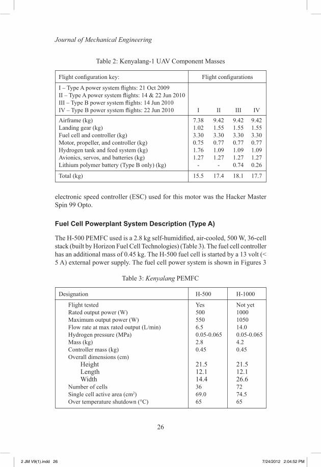
The mass of components of the UAV, as its configuration changed in different flight tests, are shown in Table 2.
Propulsion System
Electrical power generated by the fuel cell was used to drive a Hacker C5015XL (6.7:1 gear ratio) brushless DC motor. In the initial flights that occurred in October 2009 (Appendix, Table 6), a limited edition competition model was used, which was capable of operating at a maximum power of 2.2 kW (45 amps and approximately 48 volts) and produces 1,084 rpm/V. All the later test flights in 2010 were performed using a standard model, which was capable of operating at a slightly reduced maximum power of 1.7 kW (35 amps and 48 volts). The
Table 1: Kenyalang-1 UAV Airframe Dimensions
Fuselage Length 2.0 m Width 0.25 m Height 0.28 mWing Airfoil NACA 6412 Thickness to chord ratio 12% Planform surface area 3.0 m2
Span 5.0 m Root chord 0.7 m Tip chord 0.5 m Aspect ratio 8.33 Leading edge sweep 4.6° Dihedral angle 5° Aileron surface area (each) 0.21 m2
Horizontal tail Airfoil NACA 0012 Thickness to chord ratio 12% Planform surface area 0.8 m2
Span 1.65 m Chord 0.5 m Elevator surface area (all moving tail) 0.8 m2
Vertical stabilizers Planform surface area (each) 0.16 m2
Span (each) 0.4 m Leading edge sweep angle 45° Rudder surface area (each) 0.06 m2
Tail booms Length (longitudinal) 2.1 m Slant angle (upward) 15°
2 JM V9(1).indd 25 7/24/2012 2:04:52 PM
26
Journal of Mechanical Engineering
electronic speed controller (ESC) used for this motor was the Hacker Master Spin 99 Opto.
Fuel Cell Powerplant System Description (Type A)
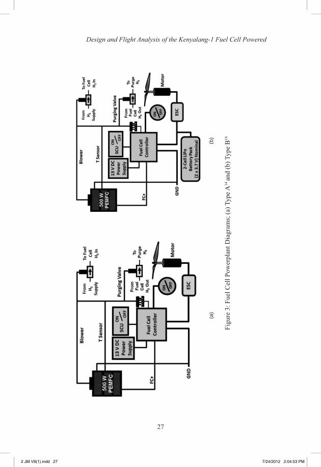
The H-500 PEMFC used is a 2.8 kg self-humidified, air-cooled, 500 W, 36-cell stack (built by Horizon Fuel Cell Technologies) (Table 3). The fuel cell controller has an additional mass of 0.45 kg. The H-500 fuel cell is started by a 13 volt (< 5 A) external power supply. The fuel cell power system is shown in Figures 3
Table 2: Kenyalang-1 UAV Component Masses
Flight configuration key: Flight configurations
I – Type A power system flights: 21 Oct 2009II – Type A power system flights: 14 & 22 Jun 2010III – Type B power system flights: 14 Jun 2010IV – Type B power system flights: 22 Jun 2010 I II III IV
Airframe (kg) 7.38 9.42 9.42 9.42Landing gear (kg) 1.02 1.55 1.55 1.55Fuel cell and controller (kg) 3.30 3.30 3.30 3.30Motor, propeller, and controller (kg) 0.75 0.77 0.77 0.77Hydrogen tank and feed system (kg) 1.76 1.09 1.09 1.09Avionics, servos, and batteries (kg) 1.27 1.27 1.27 1.27Lithium polymer battery (Type B only) (kg) - - 0.74 0.26
Total (kg) 15.5 17.4 18.1 17.7
Table 3: Kenyalang PEMFC
Designation H-500 H-1000
Flight tested Yes Not yet Rated output power (W) 500 1000 Maximum output power (W) 550 1050 Flow rate at max rated output (L/min) 6.5 14.0 Hydrogen pressure (MPa) 0.05-0.065 0.05-0.065 Mass (kg) 2.8 4.2 Controller mass (kg) 0.45 0.45 Overall dimensions (cm) Height 21.5 21.5 Length 12.1 12.1 Width 14.4 26.6 Number of cells 36 72 Single cell active area (cm2) 69.0 74.5 Over temperature shutdown (°C) 65 65
2 JM V9(1).indd 26 7/24/2012 2:04:52 PM
27
Design and Flight Analysis of the Kenyalang-1 Fuel Cell Powered
Figu
re 3
: Fue
l Cel
l Pow
erpl
ant D
iagr
ams;
(a) T
ype A
14 an
d (b
) Typ
e B
16
(a)
(b)
2 JM V9(1).indd 27 7/24/2012 2:04:53 PM
28
Journal of Mechanical Engineering
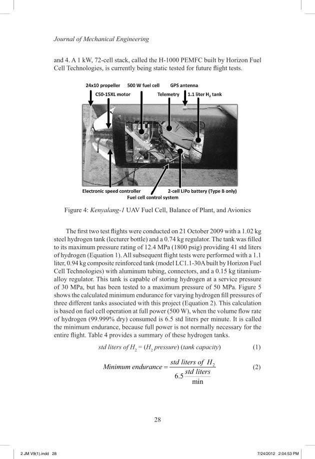
and 4. A 1 kW, 72-cell stack, called the H-1000 PEMFC built by Horizon Fuel Cell Technologies, is currently being static tested for future flight tests.
Figure 4: Kenyalang-1 UAV Fuel Cell, Balance of Plant, and Avionics
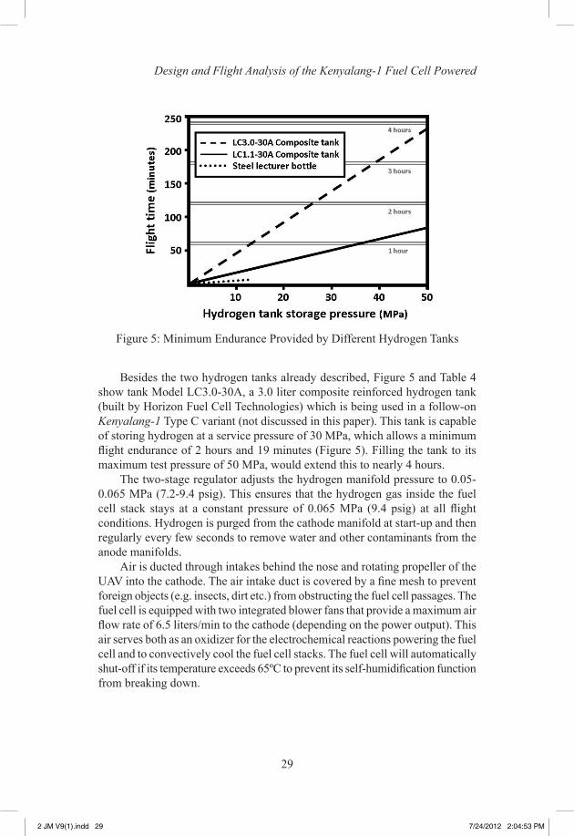
The first two test flights were conducted on 21 October 2009 with a 1.02 kg steel hydrogen tank (lecturer bottle) and a 0.74 kg regulator. The tank was filled to its maximum pressure rating of 12.4 MPa (1800 psig) providing 41 std liters of hydrogen (Equation 1). All subsequent flight tests were performed with a 1.1 liter, 0.94 kg composite reinforced tank (model LC1.1-30A built by Horizon Fuel Cell Technologies) with aluminum tubing, connectors, and a 0.15 kg titanium-alloy regulator. This tank is capable of storing hydrogen at a service pressure of 30 MPa, but has been tested to a maximum pressure of 50 MPa. Figure 5 shows the calculated minimum endurance for varying hydrogen fill pressures of three different tanks associated with this project (Equation 2). This calculation is based on fuel cell operation at full power (500 W), when the volume flow rate of hydrogen (99.999% dry) consumed is 6.5 std liters per minute. It is called the minimum endurance, because full power is not normally necessary for the entire flight. Table 4 provides a summary of these hydrogen tanks.
std liters of H2 = (H2 pressure) (tank capacity) (1)
2
6.5min
std liters of HMinimum endurancestd liters
= (2)
2 JM V9(1).indd 28 7/24/2012 2:04:53 PM
29
Design and Flight Analysis of the Kenyalang-1 Fuel Cell Powered
Besides the two hydrogen tanks already described, Figure 5 and Table 4 show tank Model LC3.0-30A, a 3.0 liter composite reinforced hydrogen tank (built by Horizon Fuel Cell Technologies) which is being used in a follow-on Kenyalang-1 Type C variant (not discussed in this paper). This tank is capable of storing hydrogen at a service pressure of 30 MPa, which allows a minimum flight endurance of 2 hours and 19 minutes (Figure 5). Filling the tank to its maximum test pressure of 50 MPa, would extend this to nearly 4 hours.
The two-stage regulator adjusts the hydrogen manifold pressure to 0.05-0.065 MPa (7.2-9.4 psig). This ensures that the hydrogen gas inside the fuel cell stack stays at a constant pressure of 0.065 MPa (9.4 psig) at all flight conditions. Hydrogen is purged from the cathode manifold at start-up and then regularly every few seconds to remove water and other contaminants from the anode manifolds.
Air is ducted through intakes behind the nose and rotating propeller of the UAV into the cathode. The air intake duct is covered by a fine mesh to prevent foreign objects (e.g. insects, dirt etc.) from obstructing the fuel cell passages. The fuel cell is equipped with two integrated blower fans that provide a maximum air flow rate of 6.5 liters/min to the cathode (depending on the power output). This air serves both as an oxidizer for the electrochemical reactions powering the fuel cell and to convectively cool the fuel cell stacks. The fuel cell will automatically shut-off if its temperature exceeds 65ºC to prevent its self-humidification function from breaking down.
Figure 5: Minimum Endurance Provided by Different Hydrogen Tanks
2 JM V9(1).indd 29 7/24/2012 2:04:53 PM
30
Journal of Mechanical Engineering
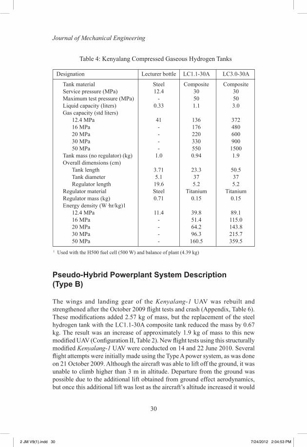
Table 4: Kenyalang Compressed Gaseous Hydrogen Tanks
Designation Lecturer bottle LC1.1-30A LC3.0-30A
Tank material Steel Composite Composite Service pressure (MPa) 12.4 30 30 Maximum test pressure (MPa) - 50 50 Liquid capacity (liters) 0.33 1.1 3.0 Gas capacity (std liters) 12.4 MPa 41 136 372 16 MPa - 176 480 20 MPa - 220 600 30 MPa - 330 900 50 MPa - 550 1500 Tank mass (no regulator) (kg) 1.0 0.94 1.9 Overall dimensions (cm) Tank length 3.71 23.3 50.5 Tank diameter 5.1 37 37 Regulator length 19.6 5.2 5.2 Regulator material Steel Titanium Titanium Regulator mass (kg) 0.71 0.15 0.15 Energy density (W·hr/kg)1 12.4 MPa 11.4 39.8 89.1 16 MPa - 51.4 115.0 20 MPa - 64.2 143.8 30 MPa - 96.3 215.7 50 MPa - 160.5 359.5
1 Used with the H500 fuel cell (500 W) and balance of plant (4.39 kg)
Pseudo-Hybrid Powerplant System Description (Type B)
The wings and landing gear of the Kenyalang-1 UAV was rebuilt and strengthened after the October 2009 flight tests and crash (Appendix, Table 6). These modifications added 2.57 kg of mass, but the replacement of the steel hydrogen tank with the LC1.1-30A composite tank reduced the mass by 0.67 kg. The result was an increase of approximately 1.9 kg of mass to this new modified UAV (Configuration II, Table 2). New flight tests using this structurally modified Kenyalang-1 UAV were conducted on 14 and 22 June 2010. Several flight attempts were initially made using the Type A power system, as was done on 21 October 2009. Although the aircraft was able to lift off the ground, it was unable to climb higher than 3 m in altitude. Departure from the ground was possible due to the additional lift obtained from ground effect aerodynamics, but once this additional lift was lost as the aircraft’s altitude increased it would
2 JM V9(1).indd 30 7/24/2012 2:04:53 PM
31
Design and Flight Analysis of the Kenyalang-1 Fuel Cell Powered
descend back toward the ground. The weight increase had reduced the thrust-to-weight ratio slightly below what was required for sustained flight. Despite this disappointing result, these “touch-and-go” flights were useful in defining the maximum weight limitation of the UAV if powered purely by the H500 fuel cell (Type A power system) and provided inspiration to create and test the Type B power system.
The rotational speed of a DC brushless motor shaft (and propeller) and hence its thrust production is dependent on the motor’s input voltage. So for this heavier UAV configuration to achieve flight, a pseudo-hybrid power system was built to augment the output voltage of the fuel cell (Type B power system). This was done by placing a 2-cell lithium polymer (LiPo) battery in series with the fuel cell. During the first two Type-B power system tests on 14 June 2010, an available Thunderpower Extreme RC V2 6-cell pack was modified so that only 2-cells provided power. The modification was necessary in order to limit the voltage supplied to the electronic speed controller (ESC), which would be damaged if it received an input exceeding 50 volts. This would have occurred if all 6-cells had been operating along with the fuel cell in open circuit. This crude (but necessary) modification added about 0.5 kg of dead weight in the 4 cells that were not used (Configuration III, Table 2). In subsequent Type B power system flight tests performed on 22 June 2010, this modified 6-cell LiPo battery was replaced by an unmodified Rybatt LiPo 2-cell pack battery (Configuration IV, Table 2). Both battery packs were capable of producing a maximum of 8.4 volts when fully charged or 7.4 volts at a nominal charge.
Avionics
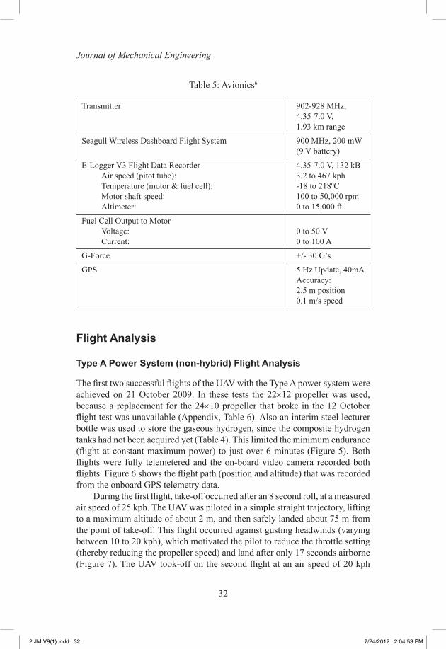
The Kenyalang-1 was equipped with a transmitter and flight data recorder to allow recording and remote transmission of flight telemetry data about the motor (temperature, shaft speed, and electrical input from the fuel cell), navigation position (altitude and Global Positioning System/GPS coordinates), airspeed, and two-axis g-force (Table 5). This data was used to analyze the flight performance of the aircraft (shown in the subsequent sections of this paper). The UAV was also equipped with a FCO (Flight Cam One) camera with a two-axis remotely pivotal head. Video recording (VGA) or still aerial photographs (VGA/JPEG) were stored on an on-board SD disk. Video (and audio) signals were also be transmitted via a 2.4 GHz transmission set. Recording occurred at 28 frames/sec with a resolution of 640 × 480 pixels (50 MB/min).
2 JM V9(1).indd 31 7/24/2012 2:04:53 PM
32
Journal of Mechanical Engineering
Flight Analysis
Type A Power System (non-hybrid) Flight Analysis
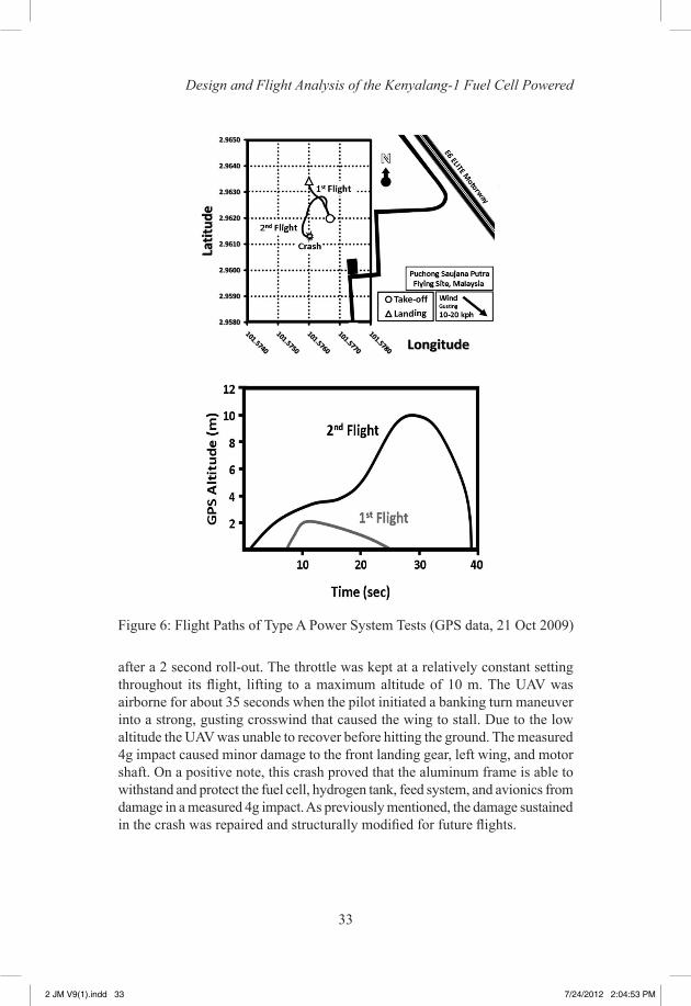
The first two successful flights of the UAV with the Type A power system were achieved on 21 October 2009. In these tests the 22×12 propeller was used, because a replacement for the 24×10 propeller that broke in the 12 October flight test was unavailable (Appendix, Table 6). Also an interim steel lecturer bottle was used to store the gaseous hydrogen, since the composite hydrogen tanks had not been acquired yet (Table 4). This limited the minimum endurance (flight at constant maximum power) to just over 6 minutes (Figure 5). Both flights were fully telemetered and the on-board video camera recorded both flights. Figure 6 shows the flight path (position and altitude) that was recorded from the onboard GPS telemetry data.
During the first flight, take-off occurred after an 8 second roll, at a measured air speed of 25 kph. The UAV was piloted in a simple straight trajectory, lifting to a maximum altitude of about 2 m, and then safely landed about 75 m from the point of take-off. This flight occurred against gusting headwinds (varying between 10 to 20 kph), which motivated the pilot to reduce the throttle setting (thereby reducing the propeller speed) and land after only 17 seconds airborne (Figure 7). The UAV took-off on the second flight at an air speed of 20 kph
Table 5: Avionics6
Transmitter 902-928 MHz, 4.35-7.0 V, 1.93 km range
Seagull Wireless Dashboard Flight System 900 MHz, 200 mW (9 V battery)
E-Logger V3 Flight Data Recorder 4.35-7.0 V, 132 kB Air speed (pitot tube): 3.2 to 467 kph Temperature (motor & fuel cell): -18 to 218ºC Motor shaft speed: 100 to 50,000 rpm Altimeter: 0 to 15,000 ft
Fuel Cell Output to Motor Voltage: 0 to 50 V Current: 0 to 100 A
G-Force +/- 30 G’s
GPS 5 Hz Update, 40mA Accuracy: 2.5 m position 0.1 m/s speed
2 JM V9(1).indd 32 7/24/2012 2:04:53 PM
33
Design and Flight Analysis of the Kenyalang-1 Fuel Cell Powered
after a 2 second roll-out. The throttle was kept at a relatively constant setting throughout its flight, lifting to a maximum altitude of 10 m. The UAV was airborne for about 35 seconds when the pilot initiated a banking turn maneuver into a strong, gusting crosswind that caused the wing to stall. Due to the low altitude the UAV was unable to recover before hitting the ground. The measured 4g impact caused minor damage to the front landing gear, left wing, and motor shaft. On a positive note, this crash proved that the aluminum frame is able to withstand and protect the fuel cell, hydrogen tank, feed system, and avionics from damage in a measured 4g impact. As previously mentioned, the damage sustained in the crash was repaired and structurally modified for future flights.
Figure 6: Flight Paths of Type A Power System Tests (GPS data, 21 Oct 2009)
2 JM V9(1).indd 33 7/24/2012 2:04:53 PM
34
Journal of Mechanical Engineering
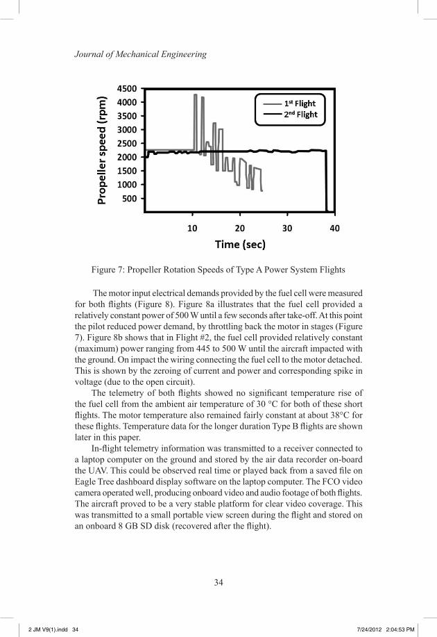
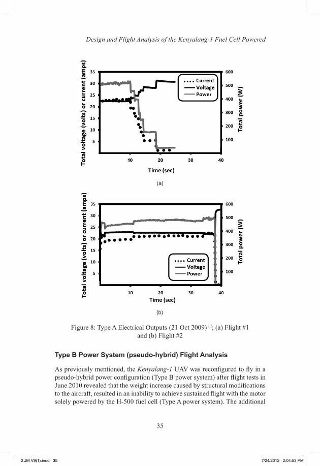
The motor input electrical demands provided by the fuel cell were measured for both flights (Figure 8). Figure 8a illustrates that the fuel cell provided a relatively constant power of 500 W until a few seconds after take-off. At this point the pilot reduced power demand, by throttling back the motor in stages (Figure 7). Figure 8b shows that in Flight #2, the fuel cell provided relatively constant (maximum) power ranging from 445 to 500 W until the aircraft impacted with the ground. On impact the wiring connecting the fuel cell to the motor detached. This is shown by the zeroing of current and power and corresponding spike in voltage (due to the open circuit).
The telemetry of both flights showed no significant temperature rise of the fuel cell from the ambient air temperature of 30 °C for both of these short flights. The motor temperature also remained fairly constant at about 38°C for these flights. Temperature data for the longer duration Type B flights are shown later in this paper.
In-flight telemetry information was transmitted to a receiver connected to a laptop computer on the ground and stored by the air data recorder on-board the UAV. This could be observed real time or played back from a saved file on Eagle Tree dashboard display software on the laptop computer. The FCO video camera operated well, producing onboard video and audio footage of both flights. The aircraft proved to be a very stable platform for clear video coverage. This was transmitted to a small portable view screen during the flight and stored on an onboard 8 GB SD disk (recovered after the flight).
Figure 7: Propeller Rotation Speeds of Type A Power System Flights
2 JM V9(1).indd 34 7/24/2012 2:04:53 PM
35
Design and Flight Analysis of the Kenyalang-1 Fuel Cell Powered
Type B Power System (pseudo-hybrid) Flight Analysis
As previously mentioned, the Kenyalang-1 UAV was reconfigured to fly in a pseudo-hybrid power configuration (Type B power system) after flight tests in June 2010 revealed that the weight increase caused by structural modifications to the aircraft, resulted in an inability to achieve sustained flight with the motor solely powered by the H-500 fuel cell (Type A power system). The additional
Figure 8: Type A Electrical Outputs (21 Oct 2009) 17; (a) Flight #1 and (b) Flight #2
(a)
(b)
2 JM V9(1).indd 35 7/24/2012 2:04:53 PM
36
Journal of Mechanical Engineering
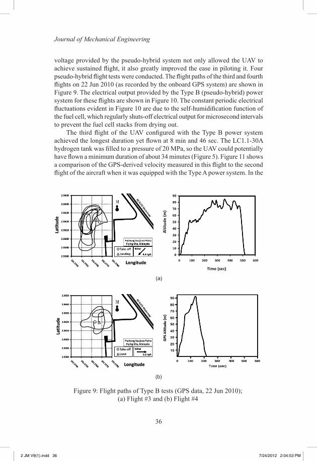
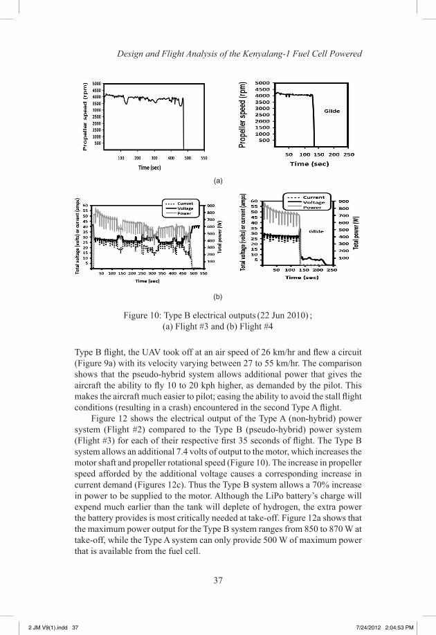
voltage provided by the pseudo-hybrid system not only allowed the UAV to achieve sustained flight, it also greatly improved the ease in piloting it. Four pseudo-hybrid flight tests were conducted. The flight paths of the third and fourth flights on 22 Jun 2010 (as recorded by the onboard GPS system) are shown in Figure 9. The electrical output provided by the Type B (pseudo-hybrid) power system for these flights are shown in Figure 10. The constant periodic electrical fluctuations evident in Figure 10 are due to the self-humidification function of the fuel cell, which regularly shuts-off electrical output for microsecond intervals to prevent the fuel cell stacks from drying out.
The third flight of the UAV configured with the Type B power system achieved the longest duration yet flown at 8 min and 46 sec. The LC1.1-30A hydrogen tank was filled to a pressure of 20 MPa, so the UAV could potentially have flown a minimum duration of about 34 minutes (Figure 5). Figure 11 shows a comparison of the GPS-derived velocity measured in this flight to the second flight of the aircraft when it was equipped with the Type A power system. In the
Figure 9: Flight paths of Type B tests (GPS data, 22 Jun 2010); (a) Flight #3 and (b) Flight #4
(a)
(b)
2 JM V9(1).indd 36 7/24/2012 2:04:53 PM
37
Design and Flight Analysis of the Kenyalang-1 Fuel Cell Powered
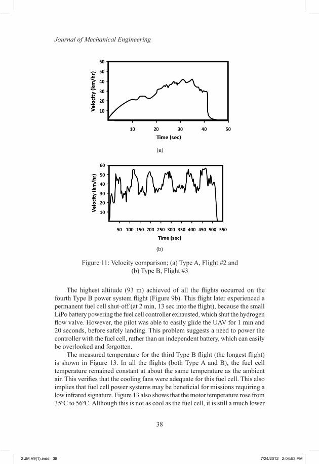
Type B flight, the UAV took off at an air speed of 26 km/hr and flew a circuit (Figure 9a) with its velocity varying between 27 to 55 km/hr. The comparison shows that the pseudo-hybrid system allows additional power that gives the aircraft the ability to fly 10 to 20 kph higher, as demanded by the pilot. This makes the aircraft much easier to pilot; easing the ability to avoid the stall flight conditions (resulting in a crash) encountered in the second Type A flight.
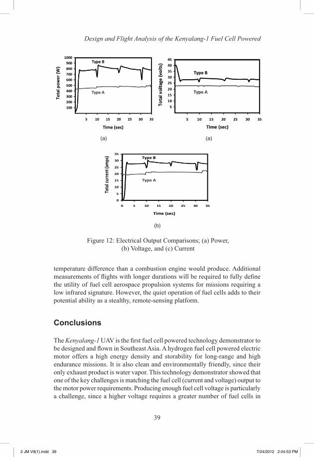
Figure 12 shows the electrical output of the Type A (non-hybrid) power system (Flight #2) compared to the Type B (pseudo-hybrid) power system (Flight #3) for each of their respective first 35 seconds of flight. The Type B system allows an additional 7.4 volts of output to the motor, which increases the motor shaft and propeller rotational speed (Figure 10). The increase in propeller speed afforded by the additional voltage causes a corresponding increase in current demand (Figures 12c). Thus the Type B system allows a 70% increase in power to be supplied to the motor. Although the LiPo battery’s charge will expend much earlier than the tank will deplete of hydrogen, the extra power the battery provides is most critically needed at take-off. Figure 12a shows that the maximum power output for the Type B system ranges from 850 to 870 W at take-off, while the Type A system can only provide 500 W of maximum power that is available from the fuel cell.
Figure 10: Type B electrical outputs (22 Jun 2010) ; (a) Flight #3 and (b) Flight #4
(a)
(b)
2 JM V9(1).indd 37 7/24/2012 2:04:53 PM
38
Journal of Mechanical Engineering
The highest altitude (93 m) achieved of all the flights occurred on the fourth Type B power system flight (Figure 9b). This flight later experienced a permanent fuel cell shut-off (at 2 min, 13 sec into the flight), because the small LiPo battery powering the fuel cell controller exhausted, which shut the hydrogen flow valve. However, the pilot was able to easily glide the UAV for 1 min and 20 seconds, before safely landing. This problem suggests a need to power the controller with the fuel cell, rather than an independent battery, which can easily be overlooked and forgotten.
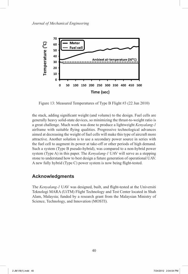
The measured temperature for the third Type B flight (the longest flight) is shown in Figure 13. In all the flights (both Type A and B), the fuel cell temperature remained constant at about the same temperature as the ambient air. This verifies that the cooling fans were adequate for this fuel cell. This also implies that fuel cell power systems may be beneficial for missions requiring a low infrared signature. Figure 13 also shows that the motor temperature rose from 35ºC to 56ºC. Although this is not as cool as the fuel cell, it is still a much lower
Figure 11: Velocity comparison; (a) Type A, Flight #2 and (b) Type B, Flight #3
(a)
(b)
2 JM V9(1).indd 38 7/24/2012 2:04:53 PM
39
Design and Flight Analysis of the Kenyalang-1 Fuel Cell Powered
temperature difference than a combustion engine would produce. Additional measurements of flights with longer durations will be required to fully define the utility of fuel cell aerospace propulsion systems for missions requiring a low infrared signature. However, the quiet operation of fuel cells adds to their potential ability as a stealthy, remote-sensing platform.
Conclusions
The Kenyalang-1 UAV is the first fuel cell powered technology demonstrator to be designed and flown in Southeast Asia. A hydrogen fuel cell powered electric motor offers a high energy density and storability for long-range and high endurance missions. It is also clean and environmentally friendly, since their only exhaust product is water vapor. This technology demonstrator showed that one of the key challenges is matching the fuel cell (current and voltage) output to the motor power requirements. Producing enough fuel cell voltage is particularly a challenge, since a higher voltage requires a greater number of fuel cells in
Figure 12: Electrical Output Comparisons; (a) Power, (b) Voltage, and (c) Current
(a)
(b)
(a)
2 JM V9(1).indd 39 7/24/2012 2:04:53 PM
40
Journal of Mechanical Engineering
the stack, adding significant weight (and volume) to the design. Fuel cells are generally heavy solid-state devices, so minimizing the thrust-to-weight ratio is a great challenge. Much work was done to produce a lightweight Kenyalang-1 airframe with suitable flying qualities. Progressive technological advances aimed at decreasing the weight of fuel cells will make this type of aircraft more attractive. Another solution is to use a secondary power source in series with the fuel cell to augment its power at take-off or other periods of high demand. Such a system (Type B pseudo-hybrid), was compared to a non-hybrid power system (Type A) in this paper. The Kenyalang-1 UAV will serve as a stepping stone to understand how to best design a future generation of operational UAV. A new fully hybrid (Type C) power system is now being flight-tested.
Acknowledgments
The Kenyalang-1 UAV was designed, built, and flight-tested at the Universiti Teknologi MARA (UiTM) Flight Technology and Test Center located in Shah Alam, Malaysia; funded by a research grant from the Malaysian Ministry of Science, Technology, and Innovation (MOSTI).
Figure 13: Measured Temperatures of Type B Flight #3 (22 Jun 2010)
2 JM V9(1).indd 40 7/24/2012 2:04:54 PM
41
Design and Flight Analysis of the Kenyalang-1 Fuel Cell Powered
Notes
1 Associate Professor, Faculty of Mechanical Engineering; [email protected]. Senior permanent member AIAA.
2 The Kenyalang is a large tropical bird native to Southeast Asia, commonly known as the “Hornbill” in English.
3 Fachhochschule (FH) Wiesbaden University of Applied Sciences, Hy-Fly website: http://www.hy-fly.de
4 Horizon Fuel Cell Technology official website: http://www.hes.sg/flights.html
5 Korea Advanced Institute of Science and Technology (KAIST) official website: http://rocket.kaist.ac.kr/03_sub_08.htm
References
[1] Hayre, R, Cha, S. W., Colella, W., and Prinz, F. B. (2006). “Fuel Cell Fundamentals”, John Wiley & Sons, Inc., ISBN-13 978-0-471-74148-0.
[2] Warshay, M. and Prokopius P. R. (1989). “The Fuel Cell in Space: Yesterday, Today, and Tomorrow”, NASA Technical Memorandum 102366, Lewis Research Center, Cleveland OH USA.
[3] McConnell, V. P. (2007). “Military UAVs claiming the skies with fuel cell power,” Fuel Cells Bulletin, 12-15.
[4] “NRL Demonstrates Fuel Cell-Powered Unmanned Aerial System”, NRL Press Release, 59-05r, (29 Nov 2005).
[5] Bradley, T. H., Moffitt, B. A., Reid, T. W., Mavris, D., and Parekh, D. E. (2006). “Test Results for a Fuel Cell powered Demonstration Aircraft,” SAE International, 2006-01-3092.
[6] Bradley, T., Moffitt, B., Mavris, D., and Parekh, D. (2007). “Development and experimental characterization of a fuel cell powered aircraft”, Journal of Power Sources, 171, 793-801.
[7] California State University Press Release (Sep 2006). “Cal State L.A.’s fuel-cell plane passes key flight test”.
2 JM V9(1).indd 41 7/24/2012 2:04:54 PM
42
Journal of Mechanical Engineering
[8] Herweth, C., Chiang, C., Ko, A., Matsuyama, S., Choi, SB, Mirmirani, M., Gamble, D., Arena, A., Koschany A., Gu, G., and Wankewycz, T. (2007). “Development of a Small Long Endurance Hybrid PEM Fuel Cell Powered UAV, “Society of Automotive Motorers Paper #2007-01-3930.
[9] Deutsches Zentrum fuer Luft- und Raumfahrt Press Release (2007). “Erfolgreicher erstflug des Hyfish”.
[10] “AeroVironment’s unmanned aircraft achieves record flight” (2007). Fuel Cells Bulletin, Vol. 2007, No.8, p. 8.
[11] Boeing Successfully Flies Fuel Cell powered Airplane (Apr 2008). Boeing Press Release.
[12] “DLR motor glider Antares takes off in Hamburg – powered by a fuel cell” (7 Jul 2009). DLR Press Release.
[13] “Ion Tiger Fuel Cell Unmanned Air Vehicle Completes 23-Hour Flight”, (2009). NRL Press Release, 99-09r,
[14] Ward, T. and Jenal, Norhisyam (2010). “Design and Initial Flight Tests of a Hydrogen Fuel Cell Powered Unmanned Air Vehicle”, ECS Transactions – 2009 Fuel Cell Seminar and Exposition, Palm Springs, CA, USA, 26(1): 433-444.
[15] “Taiwan’s first unmanned aircraft flight hybrid aircraft, Can be dual use”, (2010). Taiwan Strait, Global Military News and Report.
[16] Ward, T. and Weigi, J. (2011). Flight Studies of Hydrogen Fuel Cell Powered Propulsion Systems on an Unmanned Aircraft, Hydrogen + Fuel Cell Conference 2011, Vancouver, Canada.
2 JM V9(1).indd 42 7/24/2012 2:04:54 PM
43
Design and Flight Analysis of the Kenyalang-1 Fuel Cell Powered
Appendix
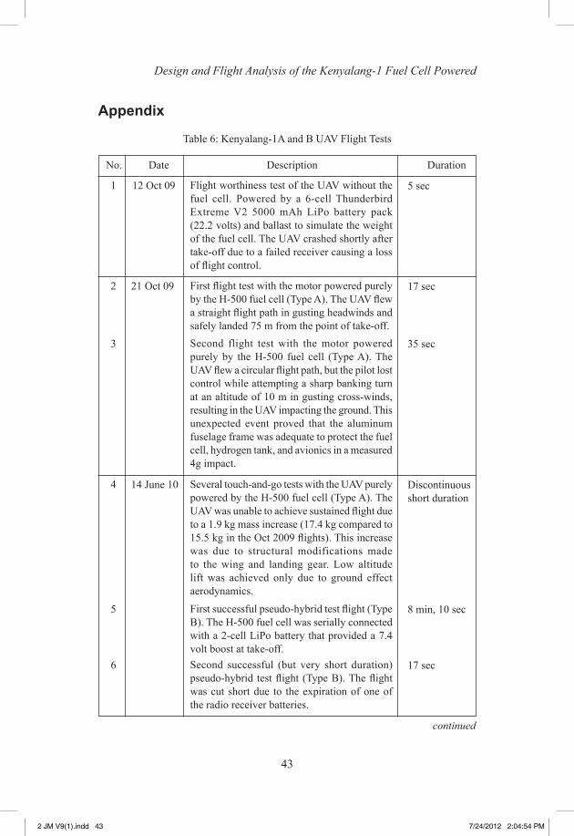
1 12 Oct 09 Flight worthiness test of the UAV without the fuel cell. Powered by a 6-cell Thunderbird Extreme V2 5000 mAh LiPo battery pack (22.2 volts) and ballast to simulate the weight of the fuel cell. The UAV crashed shortly after take-off due to a failed receiver causing a loss of flight control.
5 sec
2 21 Oct 09 First flight test with the motor powered purely by the H-500 fuel cell (Type A). The UAV flew a straight flight path in gusting headwinds and safely landed 75 m from the point of take-off.
17 sec
3 Second flight test with the motor powered purely by the H-500 fuel cell (Type A). The UAV flew a circular flight path, but the pilot lost control while attempting a sharp banking turn at an altitude of 10 m in gusting cross-winds, resulting in the UAV impacting the ground. This unexpected event proved that the aluminum fuselage frame was adequate to protect the fuel cell, hydrogen tank, and avionics in a measured 4g impact.
35 sec
4 14 June 10 Several touch-and-go tests with the UAV purely powered by the H-500 fuel cell (Type A). The UAV was unable to achieve sustained flight due to a 1.9 kg mass increase (17.4 kg compared to 15.5 kg in the Oct 2009 flights). This increase was due to structural modifications made to the wing and landing gear. Low altitude lift was achieved only due to ground effect aerodynamics.
Discontinuous short duration
5 First successful pseudo-hybrid test flight (Type B). The H-500 fuel cell was serially connected with a 2-cell LiPo battery that provided a 7.4 volt boost at take-off.
8 min, 10 sec
6 Second successful (but very short duration) pseudo-hybrid test flight (Type B). The flight was cut short due to the expiration of one of the radio receiver batteries.
17 sec
Table 6: Kenyalang-1A and B UAV Flight Tests
No. Date Description Duration
continued
2 JM V9(1).indd 43 7/24/2012 2:04:54 PM
44
Journal of Mechanical Engineering
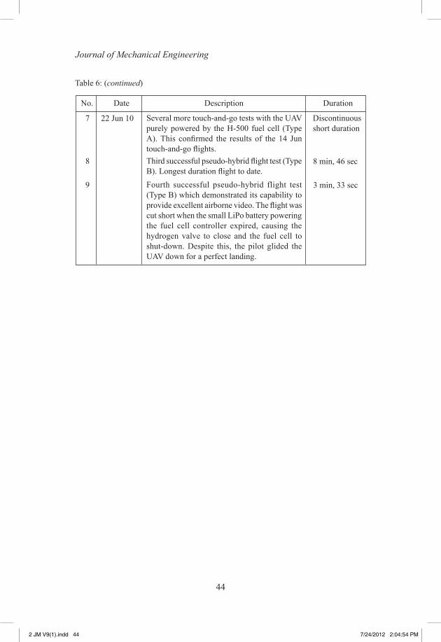
Table 6: (continued)
No. Date Description Duration
7 22 Jun 10 Several more touch-and-go tests with the UAV purely powered by the H-500 fuel cell (Type A). This confirmed the results of the 14 Jun touch-and-go flights.
Discontinuous short duration
8 Third successful pseudo-hybrid flight test (Type B). Longest duration flight to date.
8 min, 46 sec
9 Fourth successful pseudo-hybrid flight test (Type B) which demonstrated its capability to provide excellent airborne video. The flight was cut short when the small LiPo battery powering the fuel cell controller expired, causing the hydrogen valve to close and the fuel cell to shut-down. Despite this, the pilot glided the UAV down for a perfect landing.
3 min, 33 sec
2 JM V9(1).indd 44 7/24/2012 2:04:54 PM