Embed Size (px)
Citation preview
DESIGN AND FABRICATION OF SILICON GLUE GUN
NURUL ADRINA BT MOHD NASIR
Thesis submitted in fulfillment of the requirements
for the award of the Diploma in Mechanical Engineering
Faculty of Mechanical Engineering
UNIVERSITI MALAYSIA PAHANG
DECEMBER 2012
vi
ABSTRACT
The objective of this project is to design and fabricate silicon glue gun for student use at
Fluid Mechanic Laboratory in University Malaysia Pahang. The main problem with the
current silicon glue gun unit available is they easily hardened due to inappropriate action
taken by students after each use such as use plastic to cover the nozzle after usage. The
purchase of silicon glue gun by the faculty is in the big unit for the restoration purpose by
lab technician which can last long for two to three month for the normal use in the lab due
to economical reason. This resulted in wastage of product and extra spending in purchase
new units. There are three stage involves in this project. The first stage is design or
sketches few concept of the advantage of silicon glue gun. Second stage is selecting the
best concept design and the last stage is fabricating the selected design of silicon glue gun.
The fabrication process involves are marking, cutting, drilling, riveting, assembling and
finally spraying for the final touch. As a result, project objectives have been achieved.
This product may less a wasted during a maintenance work and give more benefit to the
instructor.
vii
ABSTRAK
Objektif projek ini ialah merekabentuk dan menghasilkan pistol gam silikon untuk
kegunaan pelajar di Fluid Mechanic Laboratory di Universiti Malaysia Pahang. Masalah
utama dengan unit yang sedia ada ialah unit itu cepat mengeras disebabkan oleh tindakan
yang tidak sesuai digunakan oleh para pelajar selepas digunakan seperti menggunakan
plastik untuk menutup muncung selepas digunakan. Pembelian pistol gam silicon oleh
pihak fakulti adalah dalam unit yang besar yang boleh digunakan untuk dua hingga tiga
bulan untuk kegunaan pihak makmal untuk tujuan pembaikan di dalam makmal di atas
faktor ekonomi. Ini menyebabkan pembaziran dan penambahan dalam kos disebabkan
oleh pembelian unit yang baru. Projek ini terbahagi kepada tiga peringkat. Peringkat
pertama iala merekabentuk beberapa konsep pistol gam silicon. Peringkat kedua ialah
memilih konsep yang terbaik dan peringkat terakhir ialah membentuk mengikut
rekabentuk yang dipilih. Proses pembentukan termasuklah menanda, memotong, menebuk,
merivet, menyambung dan seterusnya menyembur.
viii
TABLE OF CONTENTS
PAGE
SUPERVISOR’S DECLARATION ii
STUDENT’S DECLARATION iii
DEDICATION iv
ACKNOWLEDGEMENTS v
ABSTRACT vi
ABSTRAK vii
TABLE OF CONTENTS viii
LIST OF TABLE xi
LIST OF FIGURES xii
CHAPTER 1 INTRODUCTION
1.1 Introduction 1
1.2 Problem statement 2
1.3 Objective 2
1.4 Scopes 2
1.5 Project flow 3
CHAPTER 2 LITERATURE REVIEW
2.1 Benchmarking 7
2.1.1 Waterproof silicone sealant in a caulk gun 7
2.1.2 Electric glue gun 8
2.1.3 12ml curved tip syringe 9
2.2 Design criteria 10
2.3 Fabrication method 10
2.3.1 Cutting process 10
2.3.2 Rivet process 11
ix
2.3.3 Drilling process 12
2.3.4 Fastening 14
2.3.5 Milling process 15
CHAPTER 3 DESIGN
3.1 Introduction 17
3.2 Design 17
3.3 Design concept 18
3.3.1 Concept A 18
3.3.2 Concept B 18
3.3.3 Concept C 20
3.3 Concept selection 20
3.4 Final design 22
3.5 Bill of material 23
CHAPTER 4 FABRICATION PROCESS
4.1 Introduction 24
4.2 Process involves 24
4.3 Processes 25
CHAPTER 5 RESULT AND DISCUSSION
5.1 Introduction 29
5.2 Product 29
5.3 Product features 31
CHAPTER 6 CONCLUSION AND FUTURE RECOMMENDATION
6.1 Introduction 33
6.2 Problem encountered 33
6.3 Recommendation and future work 34
x
6.4 Conclusion and prospect 35
REFERENCES 36
APPENDICES
A Project Design 37
B Product Features 39
C Surface 41
D Project planning 43
xi
LIST OF TABLE
Table No. Title Page
3.4 Concept selection 21
3.6 Bill of material 23
xii
LIST OF FIGURES
Figure No Title Page
1.1 Project Flow Chart 4
2.1 Waterproof Silicone 7
2.2 Electric Glue Guns 8
2.3 12ml Curved Tip Syringe 9
2.4 Cutting Process 11
2.5 Rivet Tool 11
2.6 Rivet Process 12
2.7 Drilling Machine 14
2.8 Bolt and Nuts Tools 15
2.9 Milling Machine 18
3.1 Concept A 19
3.2 Concept B 19
3.3 Concept C 20
3.5 Final Designs 22
4.1 Cutting Machine 25
4.2 T-Jaw machine 26
4.3 Rivet Process 26
4.4 Rivet Tool Equipment 33
4.5 Finishing Process 27
5.1 Full View of Product 30
5.2 Top View of Product 30

xiii
5.3 Front View of Product 31
5.4 Casing Silicone Glue 32
5.5 Indicators 32
CHAPTER 1
INTRODUCTION
1.1 INTRODUCTION
Any type of metal that requires adhesive material in order to bond different pieces
together can benefit greatly from silicon glue. Commonly, silicon glue will bond quickly,
but can be applied with precision, allowing user to create the most delicate and intricate
metal easily and with minimal mess. In the same way, any repairs that require the bonding
of two items can be quickly completed with glue.
In addition, silicon glue also provides a strong bond that ensures the quality of
prepared part and component. Silicon basically strong and durable, the bonding
resultofthe silicon allows great sealing facility while attaching pieces together.
Glues are used in school project, manufacturing, shipping rooms and construction.
This is available in the familiar clear stick form, but it‟s also come in a variety shapes,
sizes and colors. Some glue sticks are multifunctional and can be used with any glue at
any temperature, but others are intended for use at only one temperature.
2
1.2 PROBLEM STATEMENT
In a fluid laboratory of mechanical engineering at University Malaysia Pahang, the
silicon glue had been applied during repair of some leakage in the lab. This is due to the
working problems that commonly happen in the tab or sinks of these workbenches. If a
tank in the lab got leakage frequently, the silicon glue gun has to be usedfrequently. Since
the lab has been used by students for their experiments so this is may the reason why the
glue gun has been always used.
Commonly, the usages of a silicon glue gun in maintenance work fluid lab involve
only a small quantity of glue. Faculty of mechanical engineering did not buy a small tube
of the silicon glue gun. By buying a small tube of glue gun, the faculty may get a
disadvantage since the price for large quantity small of glue gun will increase the cost.
Using a large size of glue its most effective since did not have to buy many times and
large glue gun its can be sustained for one or 2 months
Next is the used silicon glue being wasted since the balance of silicon becomes
hard because there is no proper cover for this type of tube.
1.3 OBJECTIVE
Based on the problem statement that mentioned previously, to overcome this
problem the objective of this project must be achieved. This objective of this project is to
fabricate and design silicone glue gun.
1.4 SCOPE
Done with objective, next is determining the scope of this project. The scope is to
ensure the project is on the boundary. Firstly is doing a benchmarking. This is focusing on
the silicon glue gun that can only use for maintenance work.
3
Next is a design concept. Which means the 3 design concepts must be created
without using a big cost. The 3 design concepts with different advantage and disadvantage
is being chosen and come out with the final concept.
Lastly is a fabrication. This is all the criteria in final design must be fulfilled. For
this 3 design concept based on the problem statement, the design must put a cover and
indicator for the final design.
1.5 PROJECT FLOW
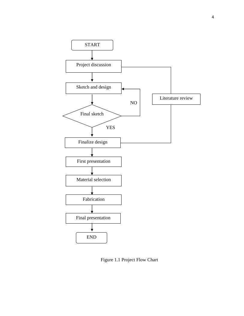
Figure 1.1 shows the flow chart of this project
4
NO
YES
Figure 1.1 Project Flow Chart
Sketch and design
Literature review
First presentation
Finalize design
Material selection
Fabrication
Final presentation
Final sketch
START
END
Project discussion
5
The project started with making a research and literature review. It is from internet,
magazines, public areas and my supervisor that related to my project. All of this literature
review takes about eight weeks. This literature review concludes with objective, scopes
and problem identification for this project. A also made a schedule management or Gantt
chart for my project.
After gathering all the information, the project will proceed with the design
process. To generate idea, firstly make a research from the internet which is more design
and example that will refer to. The final design will be chosen by sketching three design
concepts. For this final design, this best idea will be chosen for a PTA project after
discussing with the supervisor. This sketching takes about 3 weeks to be done.
This selected final design sketched is then transferred to drawing by using Solid
work program that has full dimension.
The next task is preparation for progress presentation and mid presentation this
task has to be done in one week. The presentation which is to evaluate our proposed
project has to be done at week 8. On this week, the slide for presentation has to be
prepared. Thus, before proceed with the presentation this slide has to be approved by the
supervisor.
Done this presentation, the fabrication process is started on week 9. Firstly, come
out all the list material that has to use in the fabrication process. After list all the needed
material, there are only a few materials that need to buy such as a screw, and gun rod.
Other than this, the materials are already provided by the university.
After gathering all of materials that will be used, the project will proceed with the
fabrication process. The drawing and sketching has to be used as a reference by following
the measurement and the type of material needed. The fabrication process that involved is
cutting, drilling, milling, and others. After all the parts have been processed, now it‟s the
6
time to assemble all the parts. The experiment and test the operation of the mechanism of
the silicon glue gun must be done.
Next the preparation of final presentation has to be prepared. This presentation
concludes of 30% of this final project.
Lastly, the final report or thesis has written and prepared. A report is guided by the
UMP thesis format and also guidance from supervisor. All tasks scheduled takes around
fourteen weeks to complete.
7
CHAPTER 2
LITERATURE REVIEW
2.1 BENCHMARKING
Benchmarking is a process of identifying the best product. This is typically to
measure a quality of the product and cost. Next is to compare the product with other
product and analyze the existing product. The objective of the benchmarking is to
understand and evaluate the product in the market.
2.1.1 Waterproof silicone sealants in a caulk gun
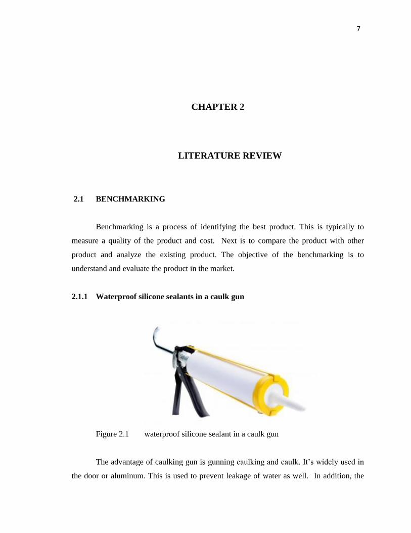
Figure 2.1 waterproof silicone sealant in a caulk gun
The advantage of caulking gun is gunning caulking and caulk. It‟s widely used in
the door or aluminum. This is used to prevent leakage of water as well. In addition, the
8
automotive industry, it also takes a shot along the edge of the glass front and rear of
vehicles is water, wind as well. The advantage of caulk gun is waterproof up to 100%
which is when the silicon being applied on sink or tab the silicon is not absorbed by water.
This disadvantage of this caulk gun is type of glue is dry, it may require time in
days or two days for the glue to dry for maximum traction. Since the silicon did not have
a proper casing so the glue is exposed to the environment. Other than that, the big force is
needed to press the grip. The grip of this glue gun is provided with a big gap to press the
grip, so the big force is needed when operate this product.
The mechanism when operate this product is first of all, hold the gun with 45
degrees between the object and the gun. Then squeeze the grip of the gun, and the glue
will turn out. Its more effective since the glue gun will turn out smoothly and more
tidiness.
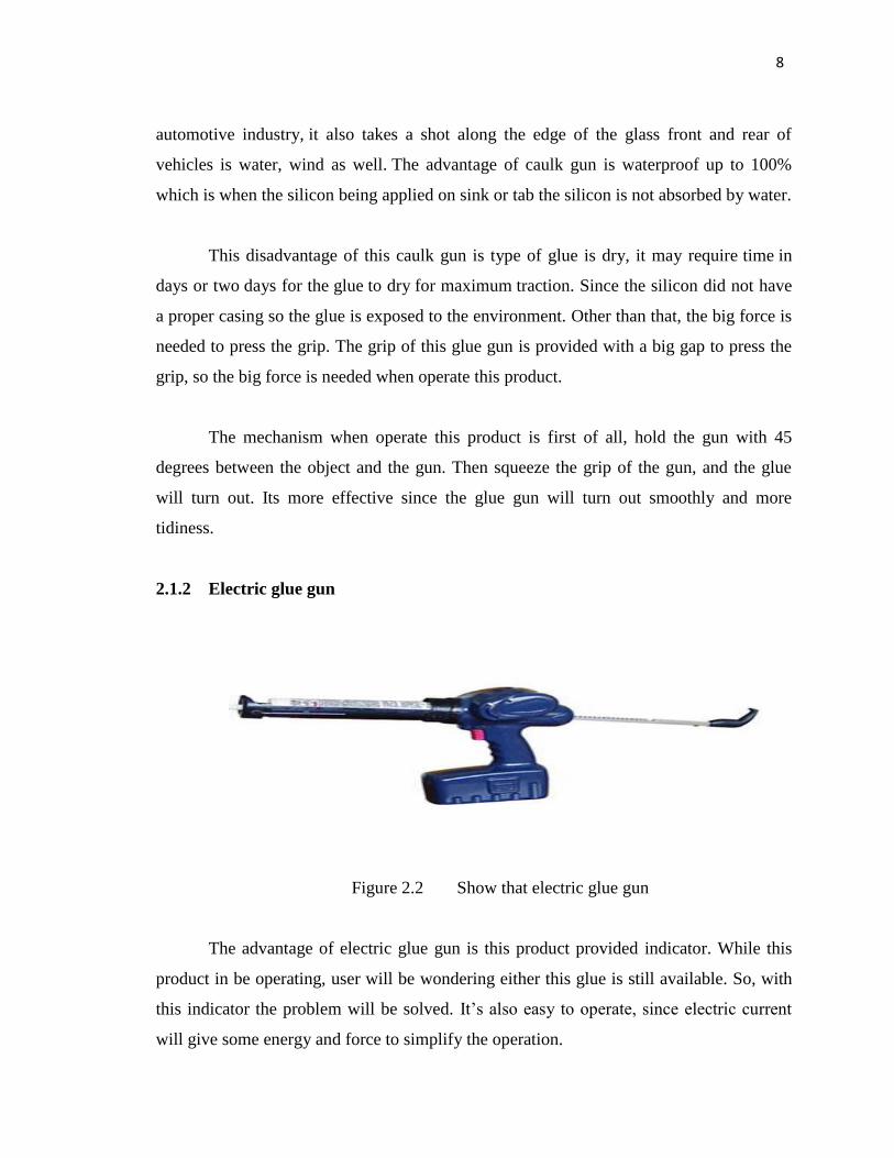
2.1.2 Electric glue gun
Figure 2.2 Show that electric glue gun
The advantage of electric glue gun is this product provided indicator. While this
product in be operating, user will be wondering either this glue is still available. So, with
this indicator the problem will be solved. It‟s also easy to operate, since electric current
will give some energy and force to simplify the operation.
9
This disadvantage of this product is electric is needed so the user has to charge
before use, so it may will waste the time.
Since this product have to charge before use, so the electric current is needed
while operating this product. Then press the button and the glue will automatically turn
out. The press button is provided with the motor so is helped to squeeze the glue gun.
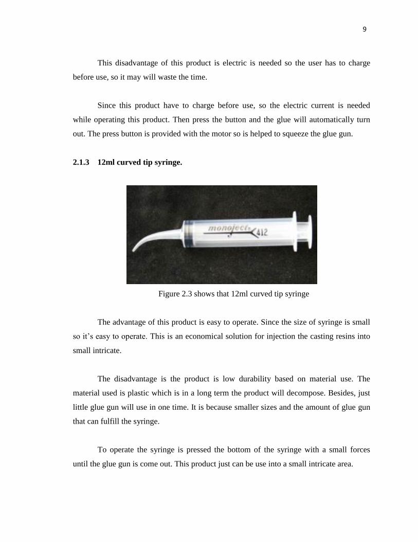
2.1.3 12ml curved tip syringe.
Figure 2.3 shows that 12ml curved tip syringe
The advantage of this product is easy to operate. Since the size of syringe is small
so it‟s easy to operate. This is an economical solution for injection the casting resins into
small intricate.
The disadvantage is the product is low durability based on material use. The
material used is plastic which is in a long term the product will decompose. Besides, just
little glue gun will use in one time. It is because smaller sizes and the amount of glue gun
that can fulfill the syringe.
To operate the syringe is pressed the bottom of the syringe with a small forces
until the glue gun is come out. This product just can be use into a small intricate area.
10
2.2 DESIGN CRITERIA
On this subtopic the design criteria must be highlighted to achieve the objective of
this project. The ideas with the better perspective are being created to ensure the design is
to be more effective and relevant. Firstly, the design criteria of this project is provide a
casing which is can close the nozzle of the tube glue gun. This result shows the wasted of
the glue gun will be reduce. Next is, at the rod to squeeze the silicone glue is create an
indicator. This indicator is helped during a maintenances work while it can be a reference
while the glue becomes run out.
2.3 FABRICATION METHOD
2.3.1 Cutting Process
Cutting processes are those in which a piece of sheet metal is separated by
applying a great enough force to cause the material to fail. The most common cutting
processes are performed by applying a shearing force, and are therefore sometimes
referred to as shearing process. When a great enough shearing force is applied, the shear
stress in the material will exceed the ultimate shear strength and the material will fail and
separate at the cut location. This shearing force is applied by two tools, one above and one
below the sheet. Whether these tools are a punch and die or upper and lower blades, the
tool above the sheet delivers a quick downward blow to the sheet metal that rests over the
lower tool
There are many types of the cutting process, which is cut round duct, straight cuts
and cut circles. Lastly, when do cutting processes please be aware with the sheet metal
edges because of razor sharp. For the safety, always wear leather or other sturdy gloves
when handling this sheet metal.
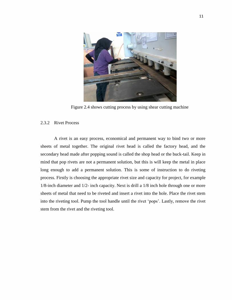
11
Figure 2.4 shows cutting process by using shear cutting machine
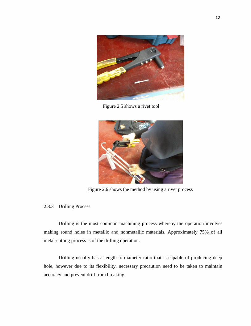
2.3.2 Rivet Process
A rivet is an easy process, economical and permanent way to bind two or more
sheets of metal together. The original rivet head is called the factory head, and the
secondary head made after popping sound is called the shop head or the buck-tail. Keep in
mind that pop rivets are not a permanent solution, but this is will keep the metal in place
long enough to add a permanent solution. This is some of instruction to do riveting
process. Firstly is choosing the appropriate rivet size and capacity for project, for example
1/8-inch diameter and 1/2- inch capacity. Next is drill a 1/8 inch hole through one or more
sheets of metal that need to be riveted and insert a rivet into the hole. Place the rivet stem
into the riveting tool. Pump the tool handle until the rivet „pops‟. Lastly, remove the rivet
stem from the rivet and the riveting tool.
12
Figure 2.5 shows a rivet tool
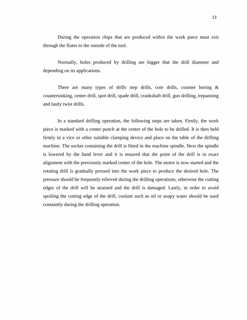
Figure 2.6 shows the method by using a rivet process
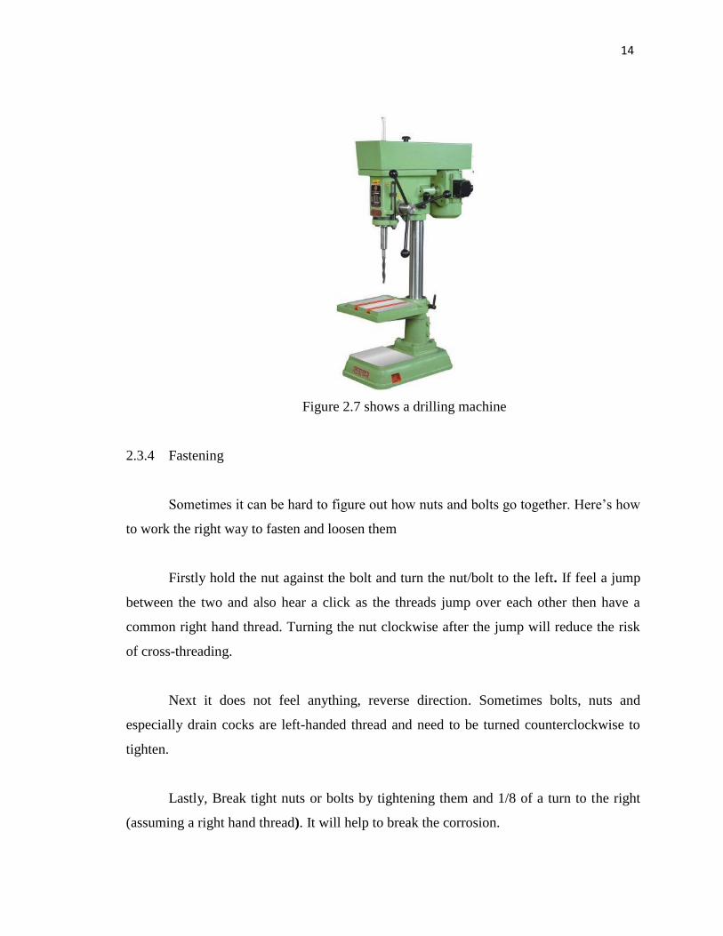
2.3.3 Drilling Process
Drilling is the most common machining process whereby the operation involves
making round holes in metallic and nonmetallic materials. Approximately 75% of all
metal-cutting process is of the drilling operation.
Drilling usually has a length to diameter ratio that is capable of producing deep
hole, however due to its flexibility, necessary precaution need to be taken to maintain
accuracy and prevent drill from breaking.
13
During the operation chips that are produced within the work piece must exit
through the flutes to the outside of the tool.
Normally, holes produced by drilling are bigger that the drill diameter and
depending on its applications.
There are many types of drills step drills, core drills, counter boring &
countersinking, center drill, spot drill, spade drill, crankshaft drill, gun drilling, trepanning
and lastly twist drills.
In a standard drilling operation, the following steps are taken. Firstly, the work
piece is marked with a center punch at the center of the hole to be drilled. It is then held
firmly in a vice or other suitable clamping device and place on the table of the drilling
machine. The socket containing the drill is fitted in the machine spindle. Next the spindle
is lowered by the hand lever and it is ensured that the point of the drill is in exact
alignment with the previously marked center of the hole. The motor is now started and the
rotating drill is gradually pressed into the work piece to produce the desired hole. The
pressure should be frequently relieved during the drilling operations, otherwise the cutting
edges of the drill will be strained and the drill is damaged. Lastly, in order to avoid
spoiling the cutting edge of the drill, coolant such as oil or soapy water should be used
constantly during the drilling operation.
14
Figure 2.7 shows a drilling machine
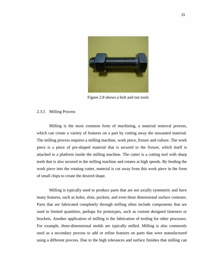
2.3.4 Fastening
Sometimes it can be hard to figure out how nuts and bolts go together. Here‟s how
to work the right way to fasten and loosen them
Firstly hold the nut against the bolt and turn the nut/bolt to the left. If feel a jump
between the two and also hear a click as the threads jump over each other then have a
common right hand thread. Turning the nut clockwise after the jump will reduce the risk
of cross-threading.
Next it does not feel anything, reverse direction. Sometimes bolts, nuts and
especially drain cocks are left-handed thread and need to be turned counterclockwise to
tighten.
Lastly, Break tight nuts or bolts by tightening them and 1/8 of a turn to the right
(assuming a right hand thread). It will help to break the corrosion.
15
Figure 2.8 shows a bolt and nut tools
2.3.5 Milling Process
Milling is the most common form of machining, a material removal process,
which can create a variety of features on a part by cutting away the unwanted material.
The milling process requires a milling machine, work piece, fixture and culture. The work
piece is a piece of pre-shaped material that is secured to the fixture, which itself is
attached to a platform inside the milling machine. The cutter is a cutting tool with sharp
teeth that is also secured in the milling machine and rotates at high speeds. By feeding the
work piece into the rotating cutter, material is cut away from this work piece in the form
of small chips to create the desired shape.
Milling is typically used to produce parts that are not axially symmetric and have
many features, such as holes, slots, pockets, and even three dimensional surface contours.
Parts that are fabricated completely through milling often include components that are
used in limited quantities, perhaps for prototypes, such as custom designed fasteners or
brackets. Another application of milling is the fabrication of tooling for other processes.
For example, three-dimensional molds are typically milled. Milling is also commonly
used as a secondary process to add or refine features on parts that were manufactured
using a different process. Due to the high tolerances and surface finishes that milling can