Embed Size (px)
Citation preview
ii
DESIGN AND FABRICATION OF GO-KART CHASSIS
MUHAMAD ASLAM BIN KAMARUDIN
A report submitted in partial fulfilment of the requirements for the award of
Diploma of Mechanical Engineering
Faculty of Mechanical Engineering
UNIVERSITI MALAYSIA PAHANG
DECEMBER 2012
vii
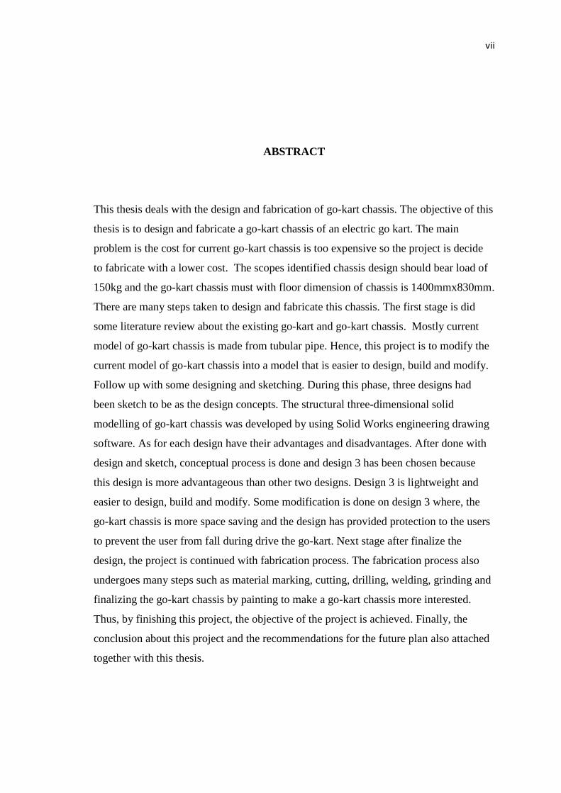
ABSTRACT
This thesis deals with the design and fabrication of go-kart chassis. The objective of this
thesis is to design and fabricate a go-kart chassis of an electric go kart. The main
problem is the cost for current go-kart chassis is too expensive so the project is decide
to fabricate with a lower cost. The scopes identified chassis design should bear load of
150kg and the go-kart chassis must with floor dimension of chassis is 1400mmx830mm.
There are many steps taken to design and fabricate this chassis. The first stage is did
some literature review about the existing go-kart and go-kart chassis. Mostly current
model of go-kart chassis is made from tubular pipe. Hence, this project is to modify the
current model of go-kart chassis into a model that is easier to design, build and modify.
Follow up with some designing and sketching. During this phase, three designs had
been sketch to be as the design concepts. The structural three-dimensional solid
modelling of go-kart chassis was developed by using Solid Works engineering drawing
software. As for each design have their advantages and disadvantages. After done with
design and sketch, conceptual process is done and design 3 has been chosen because
this design is more advantageous than other two designs. Design 3 is lightweight and
easier to design, build and modify. Some modification is done on design 3 where, the
go-kart chassis is more space saving and the design has provided protection to the users
to prevent the user from fall during drive the go-kart. Next stage after finalize the
design, the project is continued with fabrication process. The fabrication process also
undergoes many steps such as material marking, cutting, drilling, welding, grinding and
finalizing the go-kart chassis by painting to make a go-kart chassis more interested.
Thus, by finishing this project, the objective of the project is achieved. Finally, the
conclusion about this project and the recommendations for the future plan also attached
together with this thesis.
viii
ABSTRAK
Tesis ini membentangkan perkembangan mereka bentuk dan menghasilkan rangka
badan go-kart. Objektif tesis ini ialah mereka bentuk dan menghasilkan rangka badan
go-kart untuk go-kart elektrik. Masalah utama yang dihadapi adalah kos go-kart semasa
adalah terlalu mahal dan dengan projek ini ia dapat memutuskan untuk menghasilkan
reka bentuk kos yang lebih rendah. . Projek ini perlu merangkumi skop-skop berikut,
reka bentuk rangka badan go-kart dapat menampung beban 150kg dan rangka badan go-
kart mesti berlandaskan dimensi lantai rangka badan 1400mmx830mm. Terdapat
beberapa langkah-langkah yang telah diambil untuk mereka bentuk dan menghasilkan
rangka badan go-kart. Peringkat pertama adalah melakukan beberapa kajian mengenai
go-kart sedia ada dan rangka badan go-kart. Kebanyakan model semasa rangka badan
go-kart diperbuat daripada paip tiub. Oleh itu, projek ini adalah untuk mengubah suai
model semasa rangka badan go-kart ke dalam bentuk model yang lebih mudah untuk
mereka bentuk, membina dan mengubah suai. Sesulan dengan beberapa bentuk dan
lakaran. Semasa fasa ini, tiga reka bentuk telah dilakarkn untuk menjadi sebagai konsep
reka bentuk. Lukisan struktur tiga dimensi bentuk rangka badan go-kart ini telah direka
dengan menggunakan peisian lukisan kejuruteraan yang dinamakan “Solid Works”.
Setiap rekaan mempunyai kelebihan dan kekurangan masing-masing. Selesai dengan
fasa mereka dan melakar rekaan ini iaitu rekaan ini lebih ringan dan rekaan ini lebih
mudah untuk mereka bentuk, membina, dan mengubah suai berbanding dua reka bentuk
yang lain. Sedikit pengubahsuaian dilakukan ke atas rekaan 3, rangka badan go-kart
lebih jimat dari segi ruang dan reka bentuk mempunyai keselamatan kepada pengguna
untuk mengelakkan pengguna terjatuh ketika memandu go-kart. Selepas menghasilkan
lakaran reka bentuk langkah seterusnya diteruskan dengan proses penghasilan. Proses
penghasilan ini telah menjalani banyak proses tertentu seperti mengukur, menanda,
memotong bahan mentah, membuat lubang, mencantum bahagian-bahagian tertentu,
mengikir bahagian-bahagian yang terlebih semasa dicantumkan dan akhirnya
mencatkan rangka badan go-kart supaya lebih menarik. Dengan menyiapkan projek ini,
objektif projek ini tercapai. Akhir sekali, terdapat juga kesimpulan mengenai projek ini
dan perkara-perkara yang boleh diperbaiki dalam projek ini di masa hadapan dalam
tesis ini.
ix
TABLE OF CONTENTS
Page
BORANG STATUS TESIS i
FRONT PAGE ii
SUPERVISOR’S DECLARATION iii
STUDENT’S DECLARATION iv
DEDICATION v
ACKNOWLEDGEMENTS vi
ABSTRACT vii
ABSTRAK viii
TABLE OF CONTENTS ix
LIST OF TABLES xii
LIST OF FIGURES xiii
LIST OF SYMBOLS xv
LIST OF ABBREVIATIONS xvi
LIST OF APPENDIXES xvii
CHAPTER 1 INTRODUCTION
1.0 Introduction 1
1.1 Project Background 1
1.2 Problem Statement 3
1.3 Objective 3
1.4 Scope of Project 3
1.5 Project Planning 4
1.6 Thesis Outline 7
CHAPTER 2 LITERATURE REVIEW
x
2.0 Introduction 9
2.1 Chassis Design 10
2.1.1 Frame Construction 10
2.1.2 Unit-Body Construction 12
2.1.3 Space Frame Construction 13
2.2 Platform 13
2.3 The Chassis Materials 14
2.3.1 Galvanized Steel 14
2.3.2 High-Strength Steel 14
2.3.3 Alloy Steel 15
2.4 Basic Go-Kart Chassis Theories 15
2.5 Criteria of Good Chassis 16
CHAPTER 3 DESIGN CONCEPT AND SELECTION
3.0 Introduction 18
3.1 Design 18
3.1.1 Design 1 19
3.1.2 Design 2 21
3.1.3 Design 3 23
3.2 Design Comparison 25
3.3 Final Concept Selection 26
3.4 Final Concept Drawing 27
3.5 Part Design Description 27
3.6 Final Design Analysis on the Frame 30
3.7 Selected Materials 32
CHAPTER 4 FABRICATION PROCESS
4.0 Introduction 33
4.1 Fabrication Process 33
4.2 Fabrication Process Steps 34
4.2.1 Measuring and Marking 34
4.2.2 Cutting 34
xi
4.2.3 Welding 35
4.2.4 Drilling 36
4.2.5 Grinding 37
4.2.6 Painting 38
4.3 Safety Precautions in Welding Operation 38
4.3.1 General 38
4.3.2 Personal Protective Equipment 39
CHAPTER 5 RESULT AND DISCUSSION
5.0 Introduction 40
5.1 Final Product 40
5.2 Finished Product 41
5.2.1 Main Frame of the Go-kart Chassis 41
5.3 Result 41
5.4 Discussion 43
CHAPTER 6 CONCLUSION AND RECOMENDATION
6.0 Introduction 44
6.1 Problem Faced During the Project 44
6.2 Conclusion 45
6.3 Recommendations and Improvements 45
REFERENCES 47
APPENDICES 48
xii
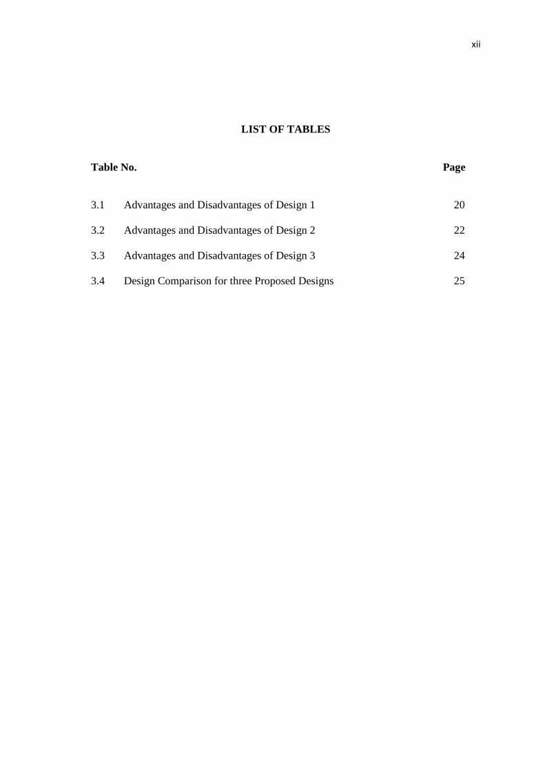
LIST OF TABLES
Table No. Page
3.1 Advantages and Disadvantages of Design 1 20
3.2 Advantages and Disadvantages of Design 2 22
3.3 Advantages and Disadvantages of Design 3 24
3.4 Design Comparison for three Proposed Designs 25
xiii
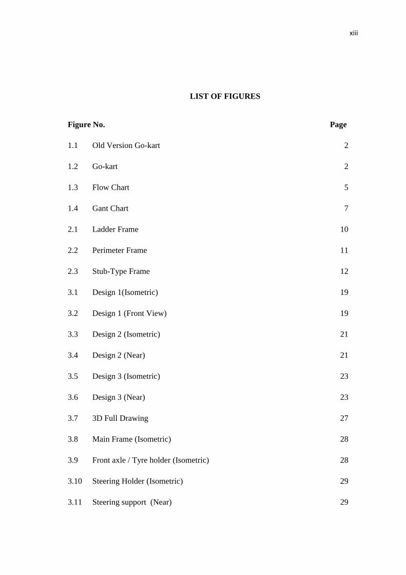
LIST OF FIGURES
Figure No. Page
1.1 Old Version Go-kart 2
1.2 Go-kart 2
1.3 Flow Chart 5
1.4 Gant Chart 7
2.1 Ladder Frame 10
2.2 Perimeter Frame 11
2.3 Stub-Type Frame 12
3.1 Design 1(Isometric) 19
3.2 Design 1 (Front View) 19
3.3 Design 2 (Isometric) 21
3.4 Design 2 (Near) 21
3.5 Design 3 (Isometric) 23
3.6 Design 3 (Near) 23
3.7 3D Full Drawing 27
3.8 Main Frame (Isometric) 28
3.9 Front axle / Tyre holder (Isometric) 28
3.10 Steering Holder (Isometric) 29
3.11 Steering support (Near) 29
xiv
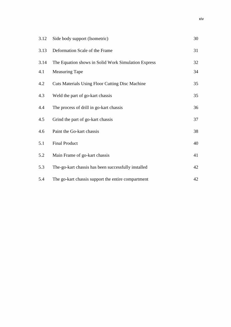
3.12 Side body support (Isometric) 30
3.13 Deformation Scale of the Frame 31
3.14 The Equation shows in Solid Work Simulation Express 32
4.1 Measuring Tape 34
4.2 Cuts Materials Using Floor Cutting Disc Machine 35
4.3 Weld the part of go-kart chassis 35
4.4 The process of drill in go-kart chassis 36
4.5 Grind the part of go-kart chassis 37
4.6 Paint the Go-kart chassis 38
5.1 Final Product 40
5.2 Main Frame of go-kart chassis 41
5.3 The-go-kart chassis has been successfully installed 42
5.4 The go-kart chassis support the entire compartment 42
xv
LIST OF SYMBOLS
kg Kilogram
mm Millimeter
m Meter
% Percent
+ Positive
- Negative
N Newton
Ø Diameter
xvi
LIST OF ABBREVIATIONS
HSS High-Strength Steel
SMAW Shielded Metal Arc Welding
UMP Universiti Malaysia Pahang
xvii
LIST OF APPENDIXES
A Drawing 48
B Bill of Materials 55
C Figures of Machines 56
D Figures of Safety Tools / Wears 59
1
CHAPTER 1
INTRODUCTION
1.0 Introduction
This chapter it will explains about the project background, project objective,
project scope and the project flow that been conducted. Besides that, it also consists
of flow chart and Gantt chart of the project which explains the overall procedure and
how time is being distributed for this project.
1.1 Project Background
Go-kart or karting was born from United States in 1950s, where the engine
mainly from discarded lawn engine. Go-kart is a driving and racing miniature,
skeleton frame, and rear engine automobiles called karts (DiNozzi. B, 1999). Go-kart
is a non popular sport previously, but today it has become one of the most popular
sports by multiple group age. Now days, racing go-karts are considered as one of the
most economic activity where a large number of people can participate. We regularly
hear about motorsports racing such as formula one, NASCAR, rally art and many
more. Those motorsport activities are out of reach of the average people because of
strict regulations and high cost. But apparently, go-kart motorsport gives chances to
public to get involved in legal racing with no restricted age and low budget needed.
Seven times formula one World Champion; Michael Schumacher started his
involvement in motorsports with karting. He joined go-kart motorsports at his
hometown, Germany and won first go-kart championship when he was 19 years old
(McCauley. J, 2008). All go-karts look alike, but the fact is go-kart have its own
classes such as sprint kart, road racing kart, indoor karting and speedway karting. In
2
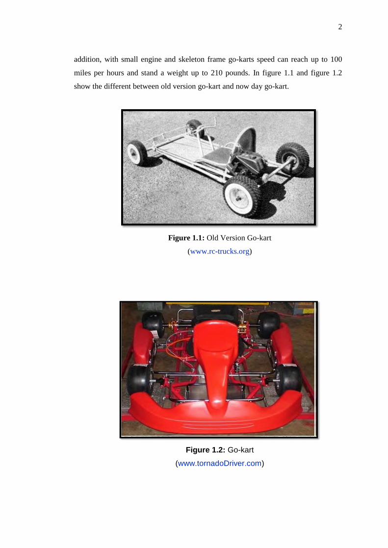
addition, with small engine and skeleton frame go-karts speed can reach up to 100
miles per hours and stand a weight up to 210 pounds. In figure 1.1 and figure 1.2
show the different between old version go-kart and now day go-kart.
Figure 1.1: Old Version Go-kart
(www.rc-trucks.org)
Figure 1.2: Go-kart
(www.tornadoDriver.com)
3
The development in karting has expanded rapidly together with advanced
technology. As this motorsport become popular among citizens, those go-karts
manufactures started to do more research and development to improve the go-kart in
terms of the chassis design, speed, braking system and transmission system. Today is
go-kart frames are made from lighter iron, chromoly and others which is more
durable and it can absorb more vibration even if it has no suspension. Designers,
engineers and others have involved directly towards new achievement in improving
all aspects in the go-kart. The usage of advance technology in manufacturing is
widely utilized to invent a better go-kart.
1.2 Problem Statement
The problem statement of this project is:
(i) To improve the skill and knowledge of Mechanical engineering
student in designing and importance of project developing go-kart.
(ii) The cost for current go-kart chassis is too expensive.
1.3 Objective
The objectives of the project are as follow:
(i) To design a go-kart chassis.
(ii) To fabricate a go-kart chassis.
1.4 Scope of Project
The scopes of project are as follow:
(i) Create conceptual design by using solid works.
(ii) Chassis design should bear load of 150kg.
(iii) The go-kart chassis with floor dimension of chassis is 1400mmx830mm.
4
1.5 Project Planning
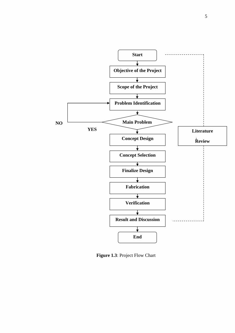
Figure 1.3 is the flow chart of the whole Final Year Project. To start this
project, an appointment with the supervisor is done to understand about the project
title given and manage the schedule of weekly meeting. The meeting with supervisor
was set up on Wednesday every week.
Problems are then indentified and objective and scopes of the project is then
fixed. Designing phase starts off by sketching few designs and models of go-kart
chassis by using manual sketch on A4 papers. Then, analyses the designs and choose
an appropriate design to finalize. Next, propose the design to the supervisor. After
that, convert the design to the three dimensional drawing using Solid Works
software.
The preparation of mid-presentation of the project is next. Before presenting,
the supervisor will see through the presentation slides and comment on corrections to
be made. Then, the presentation on the knowledge attained and instilled in the design
phase is presented to the three panels of judges.
Following up, is the survey for the materials is needed. The modification is
done on the design so as the model chassis will operate better. Once receive the
materials, start the fabrication of the go-kart chassis. Fabrication starts with the
measuring of the materials and follow up by cutting of the materials, welding the
parts together, grinding to get finishing the project and lastly painting the go-kart
chassis.
After that, the final report writing and presentation will be the last task to be
accomplished before semester break. The supervisor will review the final
presentation and revise the mistakes to be amended. The final presentation then again
will be presented to three panels. A draft report would then be submitted to the
supervisor to be point out the flaws. Corrections are done and the real final report is
handed over as completion of the final year project.
5
NO
YES
Figure 1.3: Project Flow Chart
Start
Objective of the Project
Scope of the Project
Problem Identification
Main Problem
Concept Design
Concept Selection
Finalize Design
Fabrication
Verification
Result and Discussion
End
Literature
Review
6
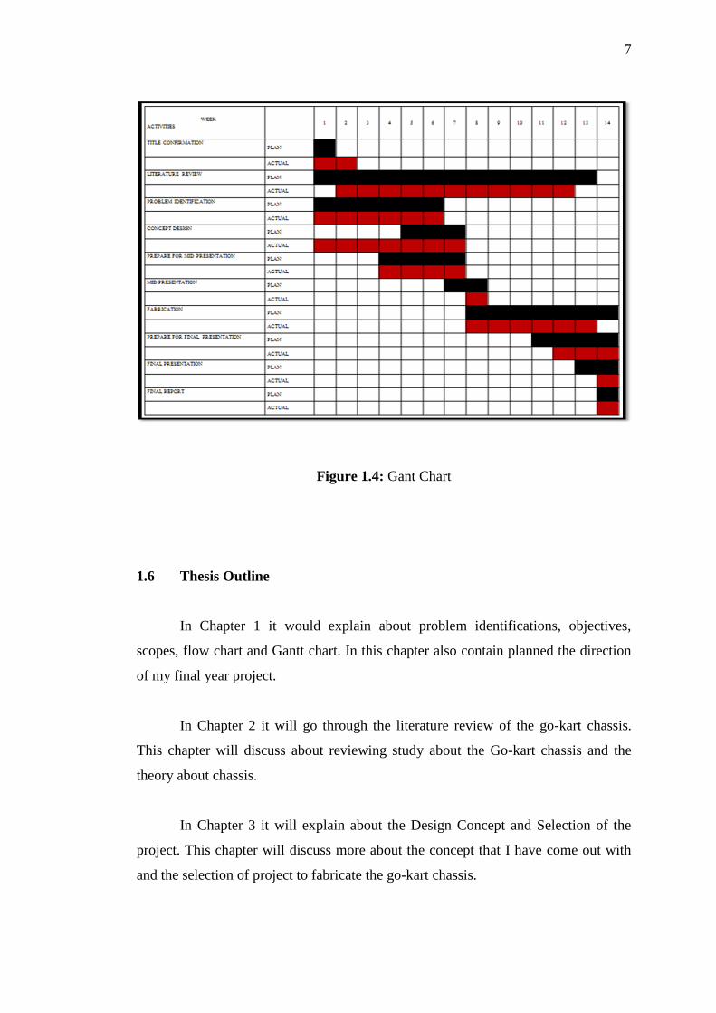
Gantt chart of this project is shown in figure 1.4. Gantt chart would show the
planning and the actual progress of the final project. It will show the difference
between the planning of the project and the actual progress of it thus allowing a
comparison to be made between two.
As shown in the Gantt chart, the time used for concept design was longer
than expected. This was because of the incompatibility of the laptop to design the
chassis. The laptop could not afford to install the suggested, Catia and the design
process has to be done using Solid Works. Besides that, the go-kart chassis
dimension must fixed with other team members tasks so it took a longer time to
create a new concept that can be fixed with other member teams.
The time used for literature review was also shorter. This was because more
focus has to be given to conceptual design and fabrication process that were delayed
due to causes that cannot be prevented.
The fabrication of the go-kart chassis also took longer time than expected
because of the limited choices of material that faculty has. The fabrication process of
the go-kart chassis also took a longer time because the facilities provided at the
workshop is not enough to be done at the appointed time for example cutting
machine problems and anything that the problems that can contribute to this factor.
Other than that, the preparation for final report also started late. It was due
to uncertainties that are caused by the delay of the fabrication process. This is
because the presentation of most of the chapters for the final report has to base on the
fabricated product.
7
Figure 1.4: Gant Chart
1.6 Thesis Outline
In Chapter 1 it would explain about problem identifications, objectives,
scopes, flow chart and Gantt chart. In this chapter also contain planned the direction
of my final year project.
In Chapter 2 it will go through the literature review of the go-kart chassis.
This chapter will discuss about reviewing study about the Go-kart chassis and the
theory about chassis.
In Chapter 3 it will explain about the Design Concept and Selection of the
project. This chapter will discuss more about the concept that I have come out with
and the selection of project to fabricate the go-kart chassis.
8
In Chapter 4 would go through the fabrication process of the selected design,
the tools and machine that were used for fabrication would also be discussed.
In Chapter 5 would then go detail on the final product that has been fabricate.
The fabricated product would explain the go-kart chassis and it would also be shown.
The result and discussion of the project would also be done in this chapter.
In Chapter 6 it contains the conclusion about the project. This chapter would
conclude the project and give some recommendation on future similar projects.
9
CHAPTER 2
LITERATURE REVIEW
2.0 Introduction
In this chapter explains about literature review would be done, which
include the theory about go-kart chassis. Usually a go-kart or owner who wants to
improve the handling of the vehicle will purchase the latest in wheels, tires and other
optional equipment, but end up finding that those things in fact handles worse. The
first stage in achieving a good handling kart that will provide the greatest percentage
of power efficiency is to go right back to basics.
The chassis is the framework of any vehicle. The suspension, steering, and
drive train components such as engine, transmission, and final drive components are
mounted to the chassis. The chassis would have to be strong and rigid platform to
support the suspension components (James D. Halderman). Furthermore, the
constructions of today are vehicles require the use of many different materials.
Chassis of go-kart is not much different from normal car chassis; in fact it is much
less complicated. The different in size and weight make go-kart chassis much easier
to design and construct.
10
2.1 Chassis Design
A typical dictionary definition of chassis usually includes terms such as
framework on which body or working parts of a vehicle, radio or television are built.
There are three basic design used today: frame, unit body, and space frame
construction.
2.1.1 Frame Construction
The frame construction usually consists of channel-shaped steel beams welded
and fastened together. The frame (chassis) of vehicle will supports all the running
gear mounted on it, it also including the engine, transmission, rear axle assembly (if
rear wheel drive), and all the suspension components.
The type of frame construction that is referred to as full frame, is so complete
that most karts can usually be driven without the body. Terms and label of different
kind of frame are as follows:
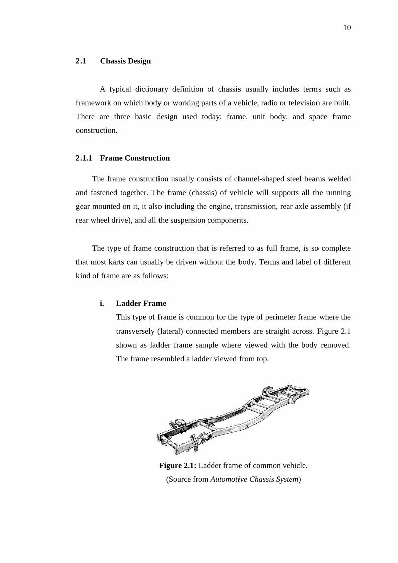
i. Ladder Frame
This type of frame is common for the type of perimeter frame where the
transversely (lateral) connected members are straight across. Figure 2.1
shown as ladder frame sample where viewed with the body removed.
The frame resembled a ladder viewed from top.
Figure 2.1: Ladder frame of common vehicle.
(Source from Automotive Chassis System)
11
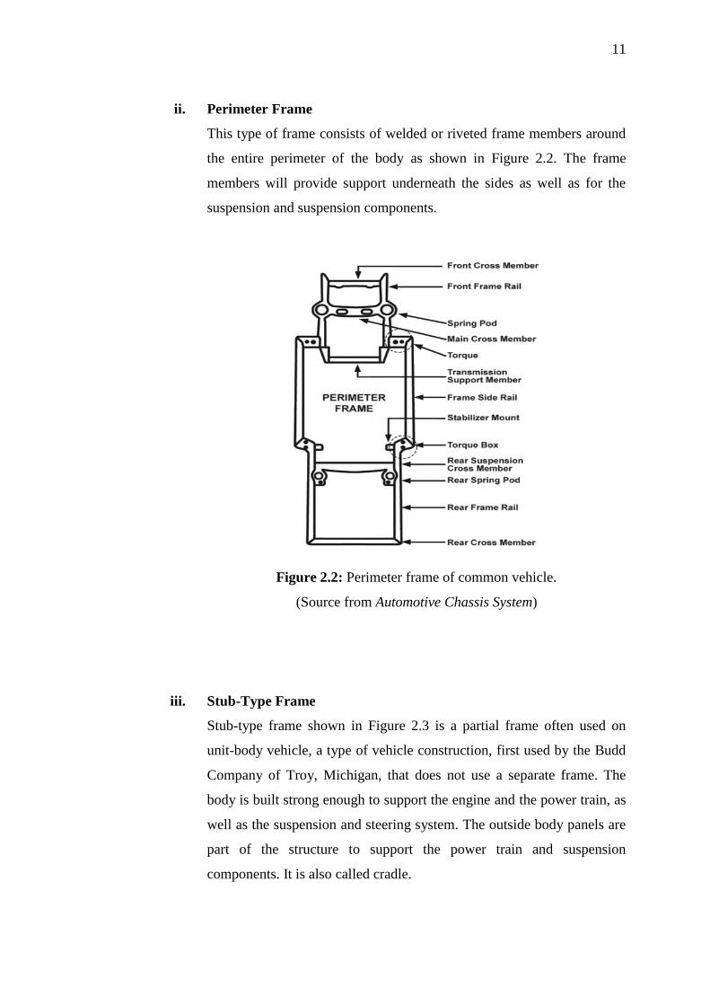
ii. Perimeter Frame
This type of frame consists of welded or riveted frame members around
the entire perimeter of the body as shown in Figure 2.2. The frame
members will provide support underneath the sides as well as for the
suspension and suspension components.
Figure 2.2: Perimeter frame of common vehicle.
(Source from Automotive Chassis System)
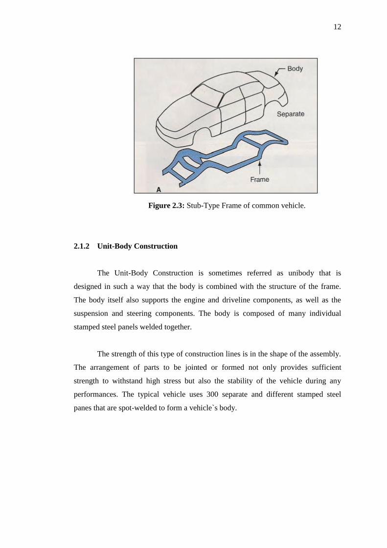
iii. Stub-Type Frame
Stub-type frame shown in Figure 2.3 is a partial frame often used on
unit-body vehicle, a type of vehicle construction, first used by the Budd
Company of Troy, Michigan, that does not use a separate frame. The
body is built strong enough to support the engine and the power train, as
well as the suspension and steering system. The outside body panels are
part of the structure to support the power train and suspension
components. It is also called cradle.
12
Figure 2.3: Stub-Type Frame of common vehicle.
2.1.2 Unit-Body Construction
The Unit-Body Construction is sometimes referred as unibody that is
designed in such a way that the body is combined with the structure of the frame.
The body itself also supports the engine and driveline components, as well as the
suspension and steering components. The body is composed of many individual
stamped steel panels welded together.
The strength of this type of construction lines is in the shape of the assembly.
The arrangement of parts to be jointed or formed not only provides sufficient
strength to withstand high stress but also the stability of the vehicle during any
performances. The typical vehicle uses 300 separate and different stamped steel
panes that are spot-welded to form a vehicle`s body.