Embed Size (px)
Citation preview

DESIGN AND FABRICATION OF COAXIAL MICRO HELICOPTER
A THESIS SUBMITTED IN PARTIAL FULFILLMENT OF THE
REQUIREMENTS FOR THE DEGREE
BACHELOR OF TECHNOLOGY
IN
MECHANICAL ENGINEERING
By:
PRATIK MISHRA 108ME002
Under The Guidance of
Prof. J. Srinivas
DEPARTMENT OF MECHANICAL ENGINEERING
NATIONAL INSTITUTE OF TECHNOLOGY
ROURKELA-769008

DESIGN AND FABRICATION OF COAXIAL MICRO HELICOPTER
A THESIS SUBMITTED IN PARTIAL FULFILLMENT OF THE
REQUIREMENTS FOR THE DEGREE
BACHELOR OF TECHNOLOGY
IN
MECHANICAL ENGINEERING
By:
PRATIK MISHRA 108ME002
DEPARTMENT OF MECHANICAL ENGINEERING
NATIONAL INSTITUTE OF TECHNOLOGY
ROURKELA-769008

i
NATIONAL INSTITUTE OF TECHNOLOGY
ROURKELA
CERTIFICATE This is to certify that the thesis entitled “Design and fabrication of coaxial micro
helicopter”submitted by Pratik Mishra (108ME002) in the partial fulfillment of
therequirements for the award of Bachelor of Technology degree in Mechanical Engineering at
National Institute of Technology Rourkela (Deemed University) is an authentic work carried out
by him under my supervision and guidance. To best of my knowledge, the matter embodied in
this thesis has not been submitted to any other University/Institute for the award of Degree or
Diploma
Date:
ProfJ.Srinivas

ii
ACKNOWLEDGEMENT
I wish to express deep sense of gratitude and indebtedness to Prof. J.Srinivas,
Department of Mechanical Engineering, N.I.T Rourkela, for introducing the
present topic and for his constant guidance, constructive criticism and valuable
suggestion throughout this project work. I also sincerely thank our senior M.tech
students, in charge of CAD LAB, for their kind help and support in my project
work.
Place:
Date:
Pratik Mishra (108ME002)
Department of Mechanical Engineering
National Institute of Technology
Rourkela - 769008

iii
CONTENTS
CERTIFICATE i
ACKNOWLEDGEMENT ii
CONTENTS iii
LIST OF FIGURES v
LIST OF SYMBOLS vii
ABSTRACT x
1.INTRODUCTION 1
1.1 Configurations 2
1.2 Coaxial configuration 2
1.3 Advantages of coaxial configuration 3
1.4 Rotor system 5
1.5 Literature review 6
2. DESIGN AND FABRICATION 9
2.1 Fabrication 10
2.2 Outer shaft 11
2.3 Inner shaft 11
2.4 Stabilizer bar 12
2.5 Upper rotor blade 14
2.6 Lower rotor blade 14
2.7 Gear arrangement 16
2.8 Tail rotor blade 17
iv
2.9 Power supply 18
2.10 Micro controller 19
2.11 Electric motors 19
2.12 Electronics interface 21
3. EQUATIONS OF MOTION 23
3.1 Newton-Euler‟s equation 23
3.2 Micro helicopter control 25
4. RESULTS AND DISCUSSIONS 26
4.1 Force analysis 26
4.1.1 Weight 26
4.1.2 Lift/Thrust Force 27
4.1.3 Drag Force 28
4.1.4 Centripetal Force 29
4.2 Finite element analysis 30
4.3 Speed of the rotor in hover condition 33
5.CONCLUSIONS 34
5.1 Summary 34
5.2 Future scope of work 35
REFERENCES 36
v
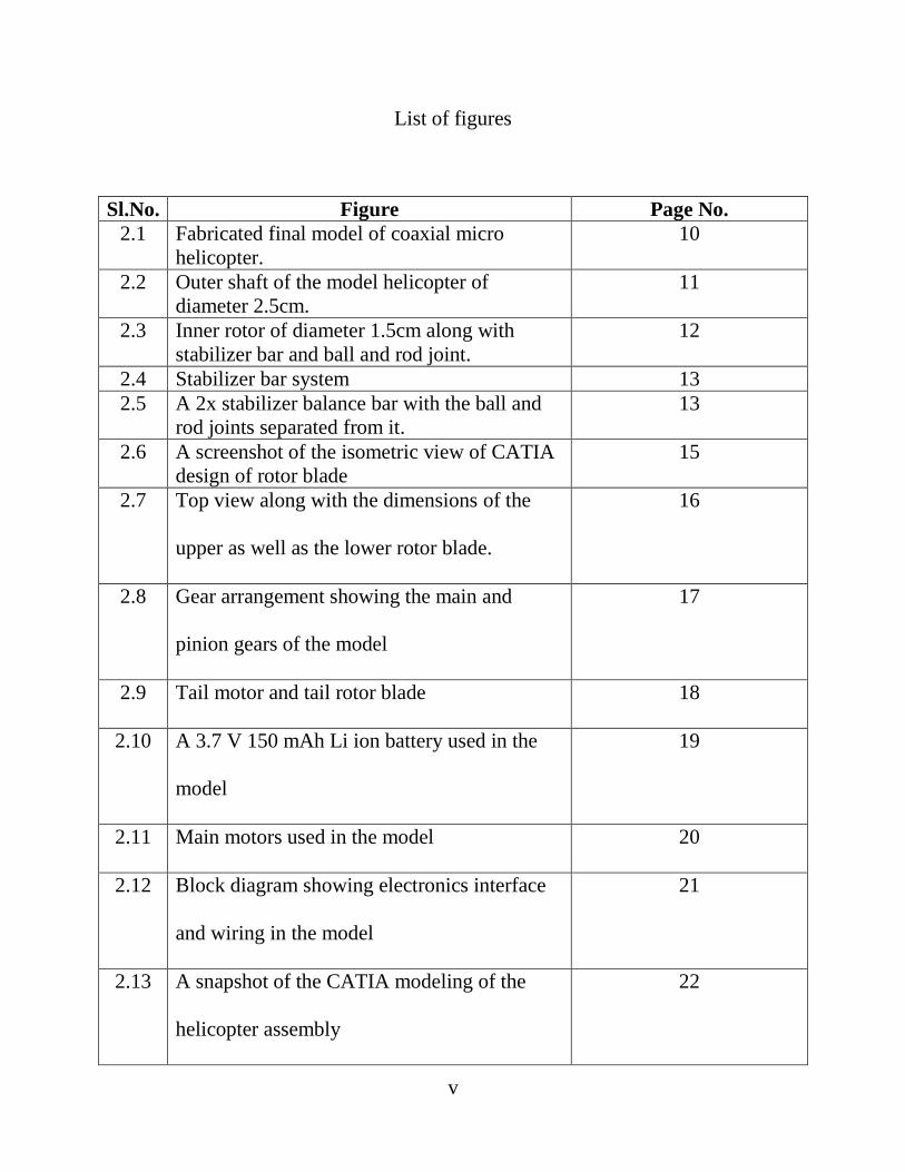
List of figures
Sl.No. Figure Page No.
2.1 Fabricated final model of coaxial micro
helicopter.
10
2.2 Outer shaft of the model helicopter of
diameter 2.5cm.
11
2.3 Inner rotor of diameter 1.5cm along with
stabilizer bar and ball and rod joint.
12
2.4 Stabilizer bar system 13
2.5 A 2x stabilizer balance bar with the ball and
rod joints separated from it.
13
2.6 A screenshot of the isometric view of CATIA
design of rotor blade
15
2.7 Top view along with the dimensions of the
upper as well as the lower rotor blade.
16
2.8 Gear arrangement showing the main and
pinion gears of the model
17
2.9 Tail motor and tail rotor blade 18
2.10 A 3.7 V 150 mAh Li ion battery used in the
model
19
2.11 Main motors used in the model 20
2.12 Block diagram showing electronics interface
and wiring in the model
21
2.13 A snapshot of the CATIA modeling of the
helicopter assembly
22

vi
3.1 Representation of the tilted thrust force with
tilting angles α and β[2]
25
4.1 Forces acting on the blade shown in a CATIA
screenshot
30
4.2 A screenshot of the von-Mises equivalent
stress analysis of the rotor blade under load in
ANSYS
31
4.3 A screenshot of the von-Mises strain analysis
of the rotor blade under load in ANSYS.
32

vii
List of symbols
Tm= Number of teeth on the main gear
Tp = Number of teeth on the pinion gear
G = Gear ratio
Nn = Nominal speed of the main motors
Na = Actual speed of the motors
V = Voltage of the Li ion battery
KV = KV rating of the main motors
η= Loss coefficient of the motor owing to frictional forces
Ω = Rotational speed of the rotor
W = Weight force on the helicopter body
Mb = Mass of 1 rotor blade
FL = Lift force on the rotor blade
CL = Coefficient of lift
Ωh = Rotational speed of rotor at hover condition
vb = Linear speed of the blade
A = Area of rotor disk
FL(t)= Total lift force acting on the helicopter
FL(b1) = Lift force acting on 1 blade
FD = Drag force
CD = Coefficient of drag
FC = Centripetal force
R = Radius of rotor disk

viii
=Acceleration in x direction
= Acceleration in y direction
=Acceleration in z direction
=Body inertia tensor
=Total external force on helicopter
= Moment vector acting on helicopter body
= Mass of the helicopter body
=Angular velocity in x direction
= Angular velocity in y direction
=Angular velocity in z direction
=Velocity in x direction
= Velocity in y direction
= Velocity in z direction
T =Magnitude of thrust
Q =Magnitude of torque
cT=Thrust coefficient

ix
cQ =Torque coefficient
kT=Thrust constant
kQ =Torque constant
tu=Thrust on upper rotor
td=Thrust on lower rotor
qu =Rotor drag torque on upper rotor
qd =Rotor drag torque on lower rotor
rCu =Distance of center of gravity from upper rotor axis
rCd =Distance of center of gravity from lower rotor axis
qgyro,u =Gyroscopic torque on upper rotor
qgyro,d =Gyroscopic torque on lower rotor
nT=Thrust vector direction
nQ=Torque vector direction
Jdrive=Moment of Inertia of the rotor blades about the rotor axis
g = Gravity vector
x
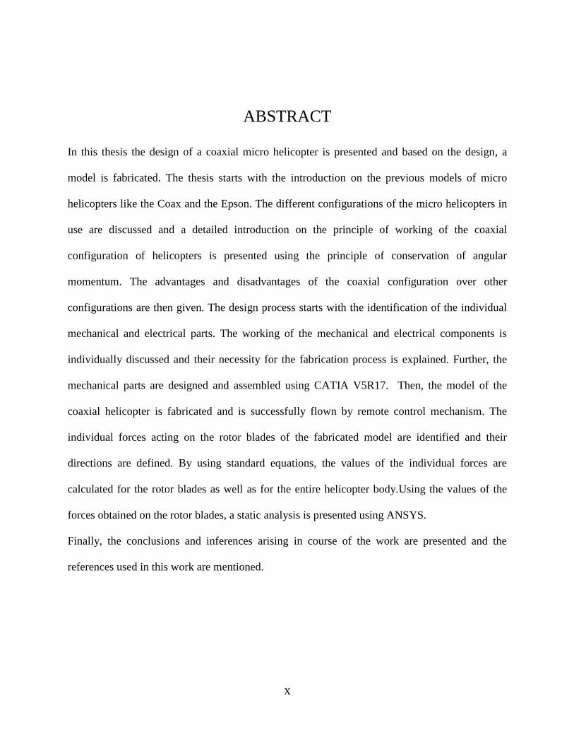
ABSTRACT
In this thesis the design of a coaxial micro helicopter is presented and based on the design, a
model is fabricated. The thesis starts with the introduction on the previous models of micro
helicopters like the Coax and the Epson. The different configurations of the micro helicopters in
use are discussed and a detailed introduction on the principle of working of the coaxial
configuration of helicopters is presented using the principle of conservation of angular
momentum. The advantages and disadvantages of the coaxial configuration over other
configurations are then given. The design process starts with the identification of the individual
mechanical and electrical parts. The working of the mechanical and electrical components is
individually discussed and their necessity for the fabrication process is explained. Further, the
mechanical parts are designed and assembled using CATIA V5R17. Then, the model of the
coaxial helicopter is fabricated and is successfully flown by remote control mechanism. The
individual forces acting on the rotor blades of the fabricated model are identified and their
directions are defined. By using standard equations, the values of the individual forces are
calculated for the rotor blades as well as for the entire helicopter body.Using the values of the
forces obtained on the rotor blades, a static analysis is presented using ANSYS.
Finally, the conclusions and inferences arising in course of the work are presented and the
references used in this work are mentioned.
1
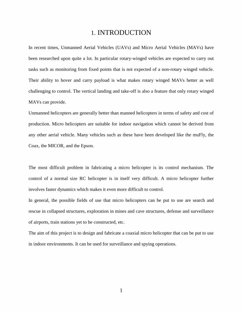
1. INTRODUCTION
In recent times, Unmanned Aerial Vehicles (UAVs) and Micro Aerial Vehicles (MAVs) have
been researched upon quite a lot. In particular rotary-winged vehicles are expected to carry out
tasks such as monitoring from fixed points that is not expected of a non-rotary winged vehicle.
Their ability to hover and carry payload is what makes rotary winged MAVs better as well
challenging to control. The vertical landing and take-off is also a feature that only rotary winged
MAVs can provide.
Unmanned helicopters are generally better than manned helicopters in terms of safety and cost of
production. Micro helicopters are suitable for indoor navigation which cannot be derived from
any other aerial vehicle. Many vehicles such as these have been developed like the muFly, the
Coax, the MICOR, and the Epson.
The most difficult problem in fabricating a micro helicopter is its control mechanism. The
control of a normal size RC helicopter is in itself very difficult. A micro helicopter further
involves faster dynamics which makes it even more difficult to control.
In general, the possible fields of use that micro helicopters can be put to use are search and
rescue in collapsed structures, exploration in mines and cave structures, defense and surveillance
of airports, train stations yet to be constructed, etc.
The aim of this project is to design and fabricate a coaxial micro helicopter that can be put to use
in indoor environments. It can be used for surveillance and spying operations.
2
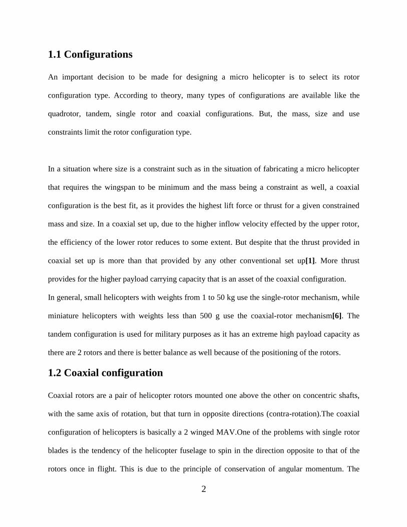
1.1 Configurations
An important decision to be made for designing a micro helicopter is to select its rotor
configuration type. According to theory, many types of configurations are available like the
quadrotor, tandem, single rotor and coaxial configurations. But, the mass, size and use
constraints limit the rotor configuration type.
In a situation where size is a constraint such as in the situation of fabricating a micro helicopter
that requires the wingspan to be minimum and the mass being a constraint as well, a coaxial
configuration is the best fit, as it provides the highest lift force or thrust for a given constrained
mass and size. In a coaxial set up, due to the higher inflow velocity effected by the upper rotor,
the efficiency of the lower rotor reduces to some extent. But despite that the thrust provided in
coaxial set up is more than that provided by any other conventional set up[1]. More thrust
provides for the higher payload carrying capacity that is an asset of the coaxial configuration.
In general, small helicopters with weights from 1 to 50 kg use the single-rotor mechanism, while
miniature helicopters with weights less than 500 g use the coaxial-rotor mechanism[6]. The
tandem configuration is used for military purposes as it has an extreme high payload capacity as
there are 2 rotors and there is better balance as well because of the positioning of the rotors.
1.2 Coaxial configuration
Coaxial rotors are a pair of helicopter rotors mounted one above the other on concentric shafts,
with the same axis of rotation, but that turn in opposite directions (contra-rotation).The coaxial
configuration of helicopters is basically a 2 winged MAV.One of the problems with single rotor
blades is the tendency of the helicopter fuselage to spin in the direction opposite to that of the
rotors once in flight. This is due to the principle of conservation of angular momentum. The
3
engine or power supply of the helicopter, by exerting torque on the rotor blades, gives substantial
angular momentum to the blades. In the absence of external forces such as ground contact, the
angular momentum of the blades must be accompanied by a change in angular momentum of the
fuselage for momentum to remain conserved. When the power supply rotates the blades, the
blades apply equal but opposite torque to the fuselage, causing the fuselage to gain angular
momentum in the opposite direction. This phenomenon will cause an imbalance of the system if
not checked. To counteract this imbalance, the tail rotor was introduced to keep giving a fixed
input of angular momentum to the helicopter body in the direction opposite to that from the main
rotor. Thus, the tail rotor acts as a counterbalance. Then, the helicopter's body remains balanced
and stable level flight can be achieved. Controlling the torque input by the tail rotor on the body
of the helicopter (hence changing the angular momentum input) helps in controlled yaw
movement. This demonstrates the extreme maneuverability of the helicopter. The helicopter can
even hover and pivot about the rotor axis. Rotational motion in designs that exclude the tail
rotors is achieved by using two sets of rotor blades rotating in opposite directions, canceling each
other's angular momentum. Coaxial rotors solve the problem arising out of imbalance of angular
momentum by turning the rotors in opposite directions to each other. The equal and opposite
torques from the rotors that act on the helicopter body, cancel each other out. Yaw control is
accomplished by increasing the rotational speed ofone rotor and decreasing that of the other.
Thus, there arises a controlled dissymmetry of torque.
1.3 Advantages of coaxial configuration
Dissymmetry of lift is an aerodynamic phenomenon caused by the rotation of a helicopter's
rotors during its forward flight. We know that the rotor blades provide lift proportional to the
volume of air flowing over their surface. From the top view of a helicopter‟s forward flight, we

4
see the rotor disk having 2 rotor blades. The rotor blades move along withthe direction of flight
for half of the rotation (advance), and then move in the opposite direction for the next half of the
rotation (retreat). During the advance, a rotor blade produces more lift. As a blade moves along
with the direction of flight, the forward motion of the aircraft increases the relative speed of the
air flowing around the blade with respect to the blade, until it reaches a maximum. At the same
time, the other rotor blade in the retreat produces comparatively less lift. As the rotor blade
moves away from the direction of flight, the relative speed of the airflow over the rotor blade,
with respect to the rotor blade, is decreased by an amount equal to the forward speed of the
aircraft, until it reaches its minimum. But, in case of coaxial rotors, the rotors reduce the effects
of dissymmetry of lift because they are 2 rotors operating in opposite directions. Hence, when 1
of the rotor blades is in retreat, a rotor blade of the other rotor blade will be in advance. Thus, we
can get a more or less constant lift.
The other benefit of coaxial configuration is that it offers more thrust and lift than any other
configuration as there are 2 rotors giving lift and there is the absence, in most cases, except in
cases of balancing, of a tail rotor that also consumes some part of the engine‟s power that can
now be used exclusively for the 2 coaxial rotors.
But the most important advantage of the coaxial rotor system is that it is an extremely compact
structure that can be used for MAVs. It occupies a very small footprint on the ground and is the
best option when size and mass are constraints.
The only major disadvantage of the coaxial system is the increased mechanical difficulty which
is overshadowed by the advantages of the configuration.

5
1.4 Rotor system
The rotor system is the rotating part of a helicopter that is responsible for generating lift. A rotor
system may be mounted horizontally as main rotors, in which case they provide lift vertically, or
it may be vertically mounted, such as a tail rotor, in which case it provides horizontal thrust to
counterbalance torque. The rotor mainly consists of a mast, hub and rotor blades.
The mast is a cylindrical shaft generally made of metal that looks like the spine of the system. At
the top of the mast is the place where the rotors are attached, which is called the hub.
In the case of the coaxial system, there are 2 masts or shafts that are coaxially mounted without
any physical contact between them both. They have a very small clearance distance. Both are
respectively mounted on their gear systems that connect them to the transmission, which is a
battery in case of micro helicopters. The rotors are hinged to the respective shafts at the hub.
Most helicopters have a single main rotor, but torque created as the engine turns the rotor against
its air drag causes the body of the helicopter to turn in the direction opposite to the rotor. Hence
to counter this effect, some sort of anti-torque mechanism must be used. Thus the tail rotor
design is introduced to balance the torque effect by pushing or pulling against the tail.
6
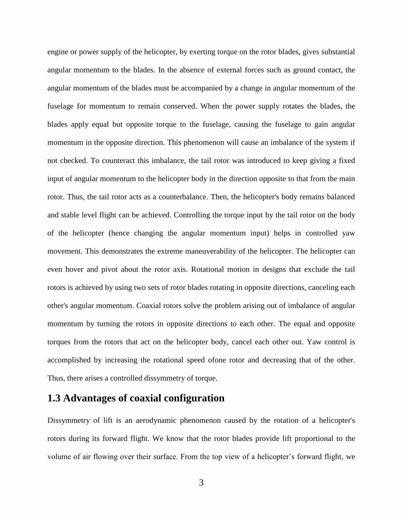
1.5 Literature review
Bermes et al.[1] presented the design of two prototypes of the autonomous micro helicopter
muFly, which were built and flown in untethered test flights. The rotor configurations and
steering principle selection are discussed and selection of coaxial configuration with swashplate
steering mechanism is justified on the basis of dynamic simulation results. The two designs are
compared and their system integration issues are solved.
Schafroth et al. [2]presented the design process of robust H∞-control for a coaxial micro
helicopter by developing a nonlinear dynamic model taking into account all the essential
elements of the helicopter. The system parameters are identified using measurement data from
test benches and CMA-ES (Covariance Matrix Adaptation Evolution Strategy). The verified
model is used for design process of H∞-controllers for attitude and heave control, which are
tested in real flight.
Sheng et al. [3]designed an autonomous takeoff and landing control strategy and implemented it
for a prototype coaxial unmanned helicopter with ducted fan configuration. The control strategy
is designed such that longitudinal and lateral controls use ground forces, attitude and drifting
feedbacks. Ground forces feedback is used to balance longitudinal forces and moments during
liftoff effectively cancelling all ground forces. Attitude and drifting feedbacks are used to
balance the longitudinal and lateral movements of the helicopter during takeoff and landing. The
flight control strategy is successfully verified during flight tests.
Bramwell et al. [4]derived thoroughly the various equations governing the motion of the rotor
blades and the various stresses acting on different parts of the blade as well as on the individual
components of the helicopter.

7
Limnaios and Tsourveloudis [5]presented the design process of a fuzzy logic based controller for
a coaxial micro helicopter and tested the developed controller for altitude, attitude, and position
control through simulations on an identified non-linear model of the helicopter.The robustness
properties of the controller to parameter variations of the model is assessed, as well as, its ability
to accommodate or absorb external disturbances.
Nonami et al.[6]presented the modeling and control system design of unmanned helicopters by
obtaining their mathematical model as a transfer function or state space equation and
subsequently, using the optimal control design for the control method for both small and
miniature unmanned helicopters.
Heyong and Zhengyin [7]solved the three-dimensional unsteady Euler equations numerically to
simulate the unsteady flows around forward flight helicopter with coaxial rotors based on
unstructured dynamic overset grids and found that the performance of both the coaxial rotors
becomes worse because of the aerodynamic interaction between them, and the influence of the
top rotor on the bottom rotor is greater than that of the bottom rotor on the top rotor. The
downwash velocity at the bottom rotor plane is much larger than that at the top rotor plane, and
the downwash velocity at the top rotor plane is a little larger than that at an individual rotor
plane. The downwash velocity and thrust coefficient both become larger when the collective
angle of blades is added. When the spacing between the two coaxial rotors increases, the thrust
coefficient of the top rotor increases, but the total thrust coefficient reduces a little, because the
decrease of the bottom rotor thrust coefficient is larger than the increase of the top rotor thrust
coefficient.
Schafroth et al. [8]investigated the aerodynamics and flight dynamics experimentally to gather
information for the design of the helicopter‟s propulsion group and steering system. Several test

8
benches are designed and built for these investigations. A coaxial rotor test bench is used to
measure the thrust and drag torque of different rotor blade designs. The effects of cyclic pitching
of the swash plate and the passive stabilizer bar are studied on a test bench measuring rotor
forces and moments with a 6–axis force sensor. The gathered knowledge is used to design a first
prototype of the muFly helicopter.
Koehl et al. [9]presented a comprehensive design of a Gun Launched Micro Air Vehicle
(GLMAV). The MAV packaged in a projectile is launched using the energy delivered by a
portable weapon. A detailed GLMAV nonlinear mathematical model is presented for hover and
near-hover flight conditions and identified from experimental load data using a strain-gage
aerodynamic balance. The parameter estimation is based on the Kalman filter estimation method
applied to the simplified aerodynamic model and using the input-output data from the
experiment. The persistently exciting condition is given in terms of physical variables of the
GLMAV through two simple expressions. The identification results are presented and validated
through comparisons between the model output and real load data.
Chen et al.[10]discussed two papers dedicated to design of unconventional and micro
UAVs..This editorial page also puts forward three papers on UAV stabilization, autonomous
flight, and intelligence control. In addition, this special issue gathers two papers on road and
terrain following and finally, there are three papers discussed focusing on path planning.
Cai et al.[11]presented a comprehensive design methodology for constructing small-scale UAV
helicopters and explain the systematic design procedure, which includes hardware component
selection and design to construct a fully functional UAV helicopter, named SheLion.

9
2. DESIGN AND FABRICATION
The design of the coaxial micro helicopter is carried out with a thorough understanding of the
working of the various mechanical elements and parts used in the fabrication of the coaxial
system. The various mechanical elements of the system are:
Outer shaft
Inner shaft
Stabilizer bar
Upper rotor blade
Lower rotor blade
Gear arrangement
Tail rotor blade
The electrical components are of equally vital significance in the fabrication the helicopter. The
different electrical components used during the course of fabrication are as follows:
Power supply (Li ion Battery)
Micro controller
Electric motors
The course of action for this chapter included a detailed design of the individual mechanical
components of the helicopter and then fabricating by assembling all the mechanical and
electrical components at the required places.

10
2.1 Fabrication
For fabrication, a toy helicopter manufactured by ZG COPTER is taken as the starting model.
Some parts of the starting model are disassembled and are incorporated in the final model of the
helicopter. Firstly, a base is created of balsa wood to mount the fuselage. The landing pad is then
constructed by cutting of a measured portion of packaging thermocol. The strip of thermocol is
then glued to the bottom side of the balsa plate using fevikwik glue. The rotor system of the
starting model is then disassembled and is mounted on the balsa plate by using fevikwik glue.
The main motors of KV rating 1600 are then mounted in the space where the motors of the
starting model were previously mounted. The tail motor and tail rotor are then disassembled and
are connected to the programmed microprocessor that is obtained from the working model. This
microprocessor is programmed according to the remote control transmitter body of the starting
model, which is also used in the final model. The Li ion battery of 3.7V 150mAh specification is
then connected to the microprocessor. For the charging requirements of the batteries of the
transmitter, a NOKIA charger‟s charging end is cut off and is connected to the charging wire of
the transmitter by solder. The points where wires are connected are then wound with cello tape to
avoid the open points to short circuit. The helicopter is then successfully flown by controlling it
with the transmitter box. The final model is shown in Fig.2.1.
Fig.2.1 Fabricated final model of coaxial micro helicopter.

11
2.2 Outer shaft
The outer shaft is connected mechanically to the lower rotor by a hinge at the hub. The rotor
blades are bolted to the hub. The outer shaft has a diameter of 2.5 cm. The upper part of the shaft
is connected to the hub that holds the lower rotor blades while the lower end of the shaft is
mounted on the bigger gear of the upper gear system as shown in Fig.2.2. The outer shaft is
made up of fiber and it rotates freely with the gear on which it is mounted.
Fig.2.2 Outer shaft of the model helicopter of diameter 2.5cm.
2.3 Inner shaft
The inner shaft lies coaxially within the outer shaft without any mechanical contact between the
two shafts. The upper end of the inner shaft is connected with the hub which holds the blades of
the upper rotor by means of bolts. The additional task that the inner shaft performs is that it
provides carries a hub that holds the stabilizer bar, which provides necessary stability to the
coaxial system. The stabilizer bar is linked to the hub of the upper rotor by a ball and rod joint
shown in Fig.2.3. The linkages involved in the inner shaft are shown in Fig.2.4. The diameter of

12
the inner shaft is 1.5cm. The lower end of the inner shaft is mounted on the larger gear of the
lower gear arrangement.
Fig.2.3 Inner rotor of diameter 1.5cm along with stabilizer bar and ball and rod joint.
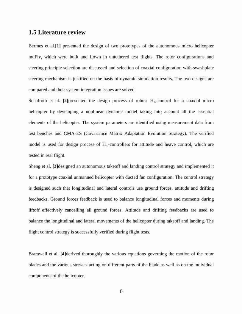
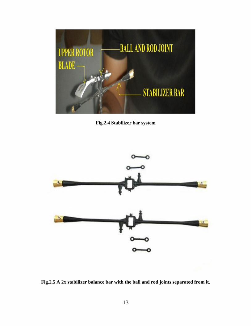
2.4 Stabilizer bar
The stabilizer bar gives cyclic pitch input to the upper rotor and stabilizes the helicopter in flight.
The stabilizer bar is linked with the upper rotor by a ball and rod joint as shown in Fig.2.3. The
upper rotor, the stabilizer bar and the ball and rod joint is considered to be a single system. In
comparison to the other parts of the helicopter, the stabilizer bar system is a massive object, i.e. it
has a high mass. Due to the resulting high inertia, this system lags behind a pitch or roll
movement of the helicopter body as shown in Fig.2.4. Thus there is a time delay for the upper
rotor and stabilizer bar to react to the movement and due to its high inertia, it exerts a redress
moment on the total system in the opposite direction of the roll/pitch movement. This redress
moment balances the helicopter in flight. The stabilizer bar used is a 9 cm long 2x stabilizer
balance bar, which is shown in Fig.2.5.
13
Fig.2.4 Stabilizer bar system
Fig.2.5 A 2x stabilizer balance bar with the ball and rod joints separated from it.
14
2.5 Upper rotor blade
The upper rotor blade used is taken from an already existent toy helicopter. The blade profile is
designed in CATIA after taking the measurements of the different physical dimensions. It is
made of polystyrene. The blade profile specifications are as follows:
Longitudinal length from hinge to free end: 6 cm.
Blade width at free end: 1.4 cm.
Blade width at hinged end: 1.9 cm.
The thickness of the blade is very small.
The isometric view of the upper blade design is shown in Fig.2.6.
2.6 Lower rotor blade
The lower rotor blade used is also detached from a previously existent toy helicopter. The
dimensions of the lower rotor blade are the same as that of the upper rotor blade. It is made of
polystyrene.
The angle of bend of the rotor blades is measured approximately using a ruler box protractor and
is found to be 22 degrees. The mass of the rotor blades is found to be 0.42 g. The mass of the
blade is measured in an air tight weighing machine in the tribology laboratory of NIT Rourkela.
The blade profile of the lower blade is also shown in the CATIA screenshot in Fig.2.5 and
Fig.2.7.

15
Fig.2.6 A screenshot of the isometric view of CATIA design of rotor blade

16
Fig.2.7 Top viewof the upper as well as the lower rotor blade along with the dimensions.
2.7 Gear arrangement
There are 2 simple sets of gears used in the model for reduction of speed of the shafts in
comparison to the motors. The motors rotate at very high speeds and it is very difficult for the
rotor blades as well as the shaft to withstand the extreme stresses developed at speeds of 5920
rpm developed in the motor. The pinion gear is mounted on the motor shaft and rotates with the
same speed as that of the motor. The motor in the model develops a speed of approximately 6000
rpm. The main gear is mounted on either the inner or shaft of the helicopter that holds the hub
that carries the blades. The main and pinion gears are meshed and therefore we get a speed
reduction for the shafts. The specifications for the gears are:
17
Number of teeth of main gear (Tm) : 70
Number of teeth of pinion gear (Tp) : 7
Gear ratio (G) : 10
The lower gear set shown in Fig.2.8 is attached to the inner shaft and the upper gear set is
attached to the outer shaft.
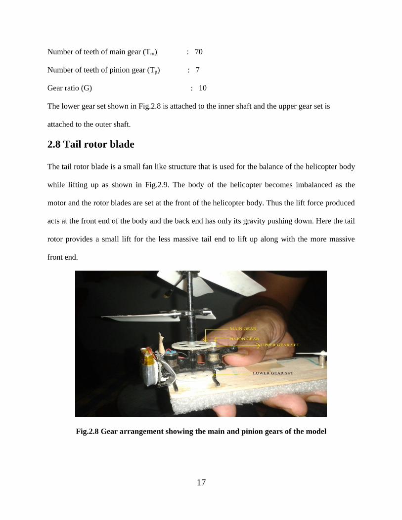
2.8 Tail rotor blade
The tail rotor blade is a small fan like structure that is used for the balance of the helicopter body
while lifting up as shown in Fig.2.9. The body of the helicopter becomes imbalanced as the
motor and the rotor blades are set at the front of the helicopter body. Thus the lift force produced
acts at the front end of the body and the back end has only its gravity pushing down. Here the tail
rotor provides a small lift for the less massive tail end to lift up along with the more massive
front end.
Fig.2.8 Gear arrangement showing the main and pinion gears of the model

18
Fig.2.9 Tail motor and tail rotor blade
2.9 Power supply
The power is supplied for the model from a 3.7 V 150mAh Li ion battery. This battery is very
useful as it provides a high power with a small size, which is shown in Fig.2.10. Due to its small
size it perfectly fits into the requirements of a micro helicopter. The battery is rechargeable up to
1000 times. The battery is directly connected to a microcontroller and it gives power to the
system through the programmed microcontroller. The specifications of the battery are:
Weight : 3.0 g
Dimensions : 4mm×17mm×19mm
Nominal voltage : 3.7 V
Charging voltage : 4.2 V
Typical capacity : 150 mAh

19
Fig.2.10A 3.7 V 150 mAh Li ion battery used in the model
2.10 Micro controller
A micro controller already programmed and used in a toy helicopter is used for the model. The
micro controller processes the inputs that are given to it via the transmitter by the help of an IR
receiver or Thin Small Outline Packtime (TSOP). This micro controller is essential for
controlling the speeds of the motors. It derives power from the LiPo battery and after processing
the signal from the transmitter sends appropriate signals to the main as well as the tail motors.
It has 2 incoming wires( 1 red and 1 black), which are negative and positive wires from the
battery and it has 6 outgoing wires( 3 reds and 3 blacks), 1 red and 1 black each as negative and
positive wires for the 3 motors.
2.11 Electric motors
The electric motors used in the model are of 2 types:
2 Main motors.
1 Tail motor.

20
The two main motors are mounted on a set up as shown in Fig.2.11. The motors have a KV
rating of 1600. They act on a voltage of 3.7 V from the LiPo battery, which gives them a nominal
speed of
Nn = V×KV = 3.7×1600 = 5920 rpm.
But due to the internal losses due to back EMF of the motor, it is assumed it offers a speed
approximately 80% of its nominal value. Hence, actual speed of motor:
Na = η×V×KV = 0.8×3.7×1600 = 4736 rpm.
Now, due to the gear system, there is a speed reduction for the shafts and consequently for the
rotor blades. Hence, the actual speed of the blades is:
Ω = η×V×KV/G
Ω = 0.8×3.7×1600/10 = 473.6 rpm.
The motors are brushless DC motors (BLDC), which weigh 3.6 g and are used because of their
superior efficiency and more lasting period in comparison to brushed motors.
Fig.2.11 Main motors used in the model
21
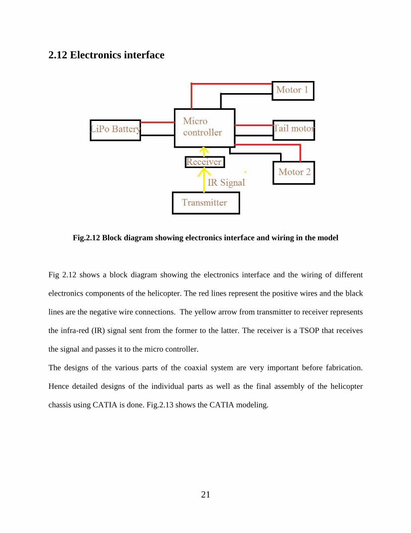
2.12 Electronics interface
Fig.2.12 Block diagram showing electronics interface and wiring in the model
Fig 2.12 shows a block diagram showing the electronics interface and the wiring of different
electronics components of the helicopter. The red lines represent the positive wires and the black
lines are the negative wire connections. The yellow arrow from transmitter to receiver represents
the infra-red (IR) signal sent from the former to the latter. The receiver is a TSOP that receives
the signal and passes it to the micro controller.
The designs of the various parts of the coaxial system are very important before fabrication.
Hence detailed designs of the individual parts as well as the final assembly of the helicopter
chassis using CATIA is done. Fig.2.13 shows the CATIA modeling.

22
Fig.2.13 A snapshot of the CATIA modeling of the helicopter assembly

23
3. EQUATIONS OF MOTION
This chapter presentsa nonlinear modeling of the dynamic forces acting on the helicopter
fuselage by considering the physics and dynamics of the different components of a coaxial micro
helicopter.
3.1 Newton-Euler’s equation
As commonly done in aeronautics, an inertial frame J and a body fixed frame B are introduced.
This gives the transformation equations for velocity, position, angles and angular rates. Using
fundamental Newtonian mechanics, the equations for rigid body motion in the body fixed frame
[2], which is located at a helicopter‟s center of gravity, are:
[ ]
*
+ *
+ (3.1)
and
[
] ( * + *
+) (3.2)
Thus far, the equations of motion are standard and are independent of flight platform.
Now the total external force fand moment m vectors are to be defined.
The forces acting on the helicopter are as follows [2]
f = tu+td+g+wdrag , (3.3)
m= qu+ qd + rCu× tu + rCd× td + qgyro,d+ qgyro,u, (3.4)
Now, the single forces and moments are defined both for lower as well as upper blade.

24
The rotor thrust [2] is ti= Ti .nTi (3.5)
And, the rotor torque [2] is qi= Qi .nQi (3.6)
Now, in hover, the thrust and torque magnitude T and Q of a rotor of radius R can be defined
as [4]
Ti = cTiπρR4Ωi
2 = cTikTΩi
2 (3.7)
Qi= cQiπρR5Ωi
2 = cQikQΩi
2, (3.8)
Here, kT = R4and kQ = R
5.
The thrust vector is described using two tilt angles α and βaround the x and y axis as
shown in Fig.3.1. The expression for thrust vectors [2] using Fig.3.1 are
nTi= [
] (3.9)
The rotor torque vectors act only in z axis but it has to be considered that, when seen from above,
the lower rotor turns clockwise while the upper rotor turns anticlockwise [2].
The next and last torque is that resulting from acceleration of rotors. It might be negligible for
lower rotor, but due to the high inertia of the upper rotor system due to the stabilizer bar, the
torque produced is noticeable. Thus, the gyroscopic torque that acts only in the rotor axis
direction is
Qgyro,i = Jdrive,i . (3.10)
Thus, the dynamic analysis is done by listing the forces and expressing them in terms of
variables.

25
Fig.3.1 Representation of the tilted thrust force with tilting angles α and β [2].
Here, Fig.3.1 shows the representation of the tilted thrust force with tilting angles α and β.
3.2 Micro helicopter control
Control structure for full control of a micro helicopter consists of 6 independent controllers [5].
1.Altitude control
2. Yaw control
3. Pitch and Roll control
The x and y position controllers generate reference inputs to be tracked by pitch and roll
controllers.

26
4. RESULTS AND DISCUSSIONS
4.1 Force calculations
There are a number of forces acting on the rotor blades that are analyzed using ANSYS. First of
all the forces are identified. The first force that acts on the rotor blades is its own weight
downwards at its center of gravity. The second force is the lift/thrust force that acts on the blades
on account of the cutting of airstream by the curvature of the blades. Thirdly, as the blades rotate,
they cut the airstream and therefore, the airstream also exerts a force on the blades due to the air
resistance. This is the drag force that acts on the blades of the rotor. And finally, on account of
the rotation of the rotor blades, there acts a centrifugal force on the blades.
The next step is to consider the forces separately and find out their values for the rotor blades
individually.
4.1.1 Weight
Due to the mass of the blades, there acts a weight force downwards at the center of gravity of the
blades. An individual blade is considered and the force value is found for it. Now, we know that:
W = Mbg (4.1)
The mass of an individual blade is measured in the air tight weighing machine in the tribology
laboratory of NIT Rourkela and is found to be 0.29 g.
Hence, W = 0.29×10-3
×9.8
W = .002842 N.
And, weight of the helicopter body of mass 20.2g is
Wb = .0202×9.8 = 0.19796 N.

27
4.1.2 Lift/Thrust Force
When the blade cuts across an airstream, there is a flow of air both above and below the blade.
The blade profile is such that the air that passes above the blade has to travel more distance in the
same time as compared to the air that passes below the blade. Hence, the air that passes above
the blade has a higher velocity than the air that passes below it. Now, according to Bernoulli‟s
principle, the fluid having higher velocity is at a lower pressure. Hence, the air above the blade,
due to its higher velocity, is at a lower pressure. That means there is a pressure difference
between the air above and below the blade. Thus there arises a force from the high pressure
region to the low pressure region. This is the lift force that acts essentially in the upward
direction due to the blade profile.
The lift force on a blade is given approximately by:
FL = 0.5×CL×ρ×vb2×A (4.2)
Now, the area A is the area of the total rotor disk. So, area A is given by:
A = πR2 (4.3)
Here, R = 6cm. So, area of the rotor disk is:
A = 3.14×(0.06)2
A = 0.011304 m2
Here CL is assumed to be 1.6, a typical lift coefficient value.
Density of air is taken as 1.29 kg/m3. So, ρ = 1.29 kg/m
3.
The angular velocity of the blades Nb is already found out in 2.10 to be 473.6 rpm.
The rotational speed Ω of the blades is: Ω = 473.6/60 = 7.894 rev/s
So, the linear velocity of blades in m/s is:
vb= 7.894×2×π×0.06 = 2.974 m/s.
28
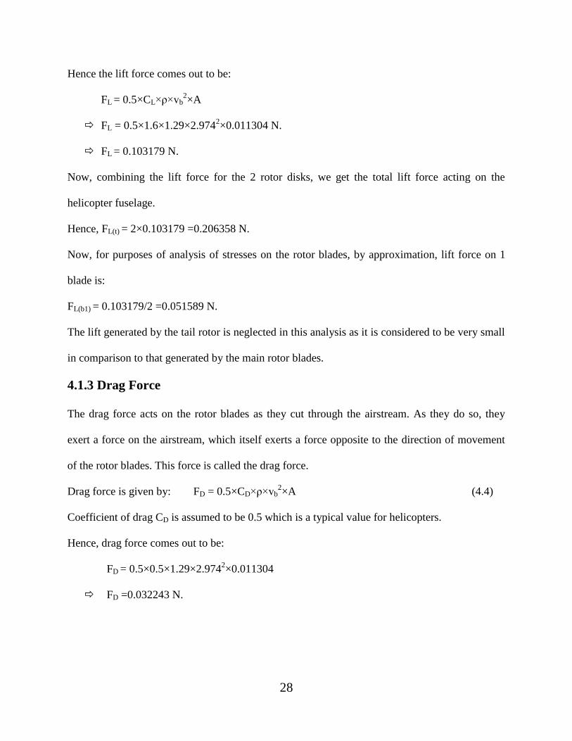
Hence the lift force comes out to be:
FL = 0.5×CL×ρ×vb2×A
FL = 0.5×1.6×1.29×2.9742×0.011304 N.
FL = 0.103179 N.
Now, combining the lift force for the 2 rotor disks, we get the total lift force acting on the
helicopter fuselage.
Hence, FL(t) = 2×0.103179 =0.206358 N.
Now, for purposes of analysis of stresses on the rotor blades, by approximation, lift force on 1
blade is:
FL(b1) = 0.103179/2 =0.051589 N.
The lift generated by the tail rotor is neglected in this analysis as it is considered to be very small
in comparison to that generated by the main rotor blades.
4.1.3 Drag Force
The drag force acts on the rotor blades as they cut through the airstream. As they do so, they
exert a force on the airstream, which itself exerts a force opposite to the direction of movement
of the rotor blades. This force is called the drag force.
Drag force is given by: FD = 0.5×CD×ρ×vb2×A (4.4)
Coefficient of drag CD is assumed to be 0.5 which is a typical value for helicopters.
Hence, drag force comes out to be:
FD = 0.5×0.5×1.29×2.9742×0.011304
FD =0.032243 N.

29
4.1.4 Centrifugal Force
As the blade rotates at a very high speed of 473.6 rpm, there is a force acting towards the center
of the hub along the plane of the blade. This force is the centrifugal force which is an inherent
force for any rotating body.
The centrifugal force is given by:
FC = MbΩ2R (4.5)
FC = 0.29×10-3
×(473.6/60)2×0.06
FC = 0.001084 N.
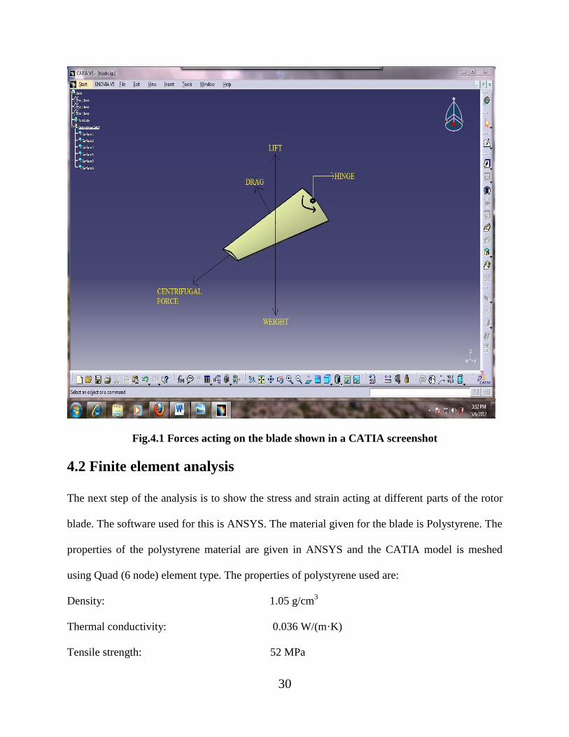
Fig.4.1 shows the various forces acting on the CATIA model of the rotor blade. The weight acts
downwards at the center of gravity. The lift force acts at the center of gravity as well but
upwards. The drag force acts opposite to the direction of motion of the rotor blade as shown.
And finally, the centrifugal force acts away from the hinge as shown.
30
Fig.4.1 Forces acting on the blade shown in a CATIA screenshot
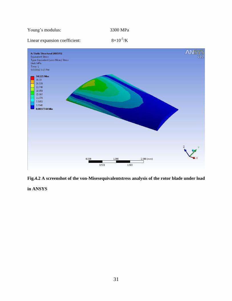
4.2 Finite element analysis
The next step of the analysis is to show the stress and strain acting at different parts of the rotor
blade. The software used for this is ANSYS. The material given for the blade is Polystyrene. The
properties of the polystyrene material are given in ANSYS and the CATIA model is meshed
using Quad (6 node) element type. The properties of polystyrene used are:
Density: 1.05 g/cm3
Thermal conductivity: 0.036 W/(m·K)
Tensile strength: 52 MPa
31
Young‟s modulus: 3300 MPa
Linear expansion coefficient: 8×10⁻⁵
/K
Fig.4.2 A screenshot of the von-Misesequivalentstress analysis of the rotor blade under load
in ANSYS
32
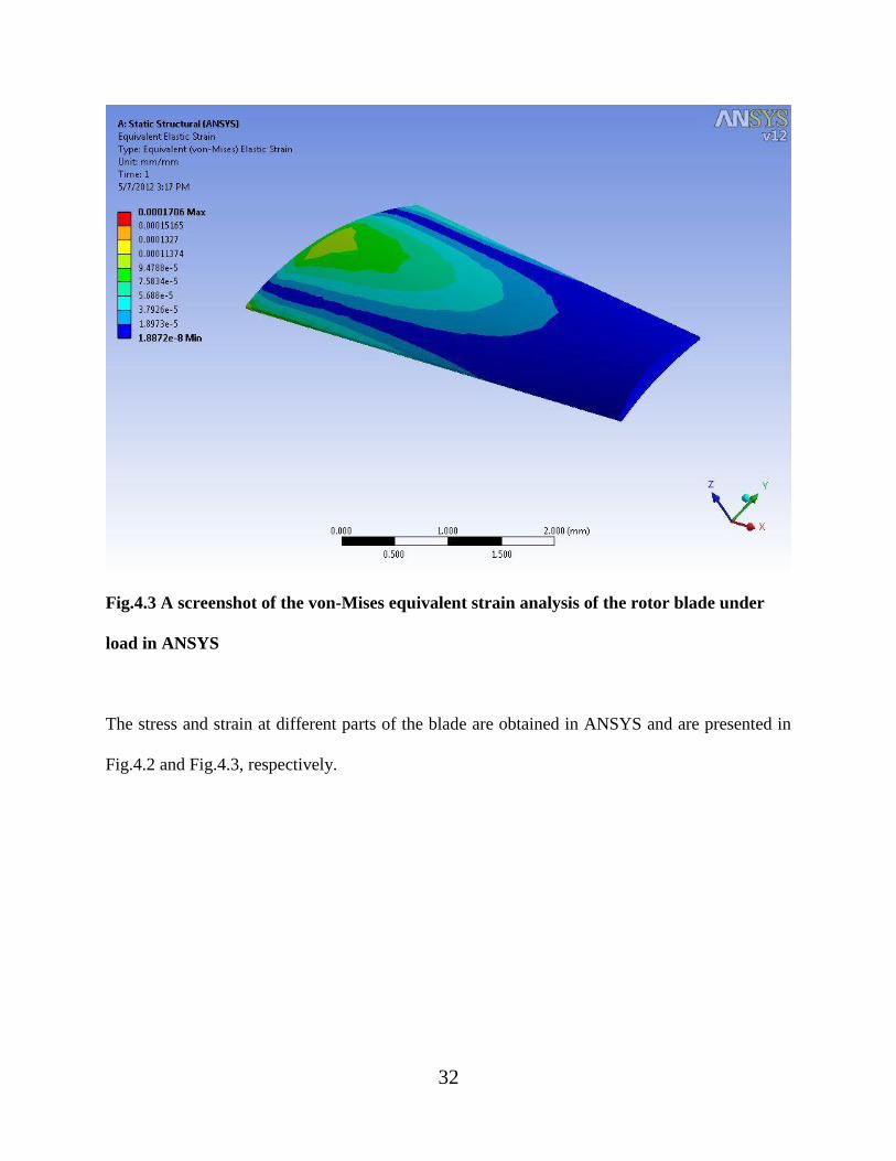
Fig.4.3 A screenshot of the von-Mises equivalent strain analysis of the rotor blade under
load in ANSYS
The stress and strain at different parts of the blade are obtained in ANSYS and are presented in
Fig.4.2 and Fig.4.3, respectively.

33
4.3 Speed of the rotor in hover condition
At hover condition, the lift force and the weight of the helicopter balance each other out. Hence.
Lift force on 2 rotor disks = Weight of helicopter body.
2×0.5×CL×ρ×vb2×A = Wb
1.6×1.29×vb2×0.011304= 0.19796
vb= 2.912 m/s = 7.73 rev/s
Ωh = 463.82 rpm.
This is the speed of the rotor at which the helicopter hovers and this is the speed at which the
helicopter takes off because at this speed, the lift generated just equals the weight of the
helicopter and as the speed increases from this value, the lift force keeps increasing and the
weight remains the same.
34
5. CONCLUSIONS
5.1 Summary
In this work, an attempt is made to design and fabricate a coaxial micro helicopter. The dynamic
forces are evaluated and static analysis is carried out in ANSYS. Even though there are no
noticeable conclusions, the following is observed:
1. Speed of the rotor is obtained in section 2.11 as 473.6 rpm and at that speed of the rotor,
the lift generated is found to be 0.206358 N in section 4.1.2. This lift force is found to be
greater than the weight of the helicopter, which is found to be 0.19796 N in section 4.1.1.
Thus, the lift force generated is calculated to be greater than the weight of the helicopter,
which is the necessary condition for take-off. This result is confirmed in the fabricated
model which takes off as expected.
2. Speed of the rotor in hover condition is found out be 463.82 rpm in section 4.3. This is
the speed at take-off state of the helicopter. Thus, it is concluded that the speed of the
rotor must lie between the limit values of 463.82 rpm and 473.6 rpm for the helicopter to
be in flight. Any speed less than 463.82 rpm will result in the lift force to be less than the
weight for which the helicopter will not take off or if in flight, will fall down.
3. The ANSYS analysis for von-Mises stress in Fig.4.2 shows that the hinged tip of the
rotor blade experiences a stress in the limit from 18.958 MPa to 22.748 MPa. As this
range of values is less than the tensile strength of polystyrene, which is 52 MPa, therefore
no signs of fracture are observed and the analysis is safe. The free tip of the rotor blade
experiences a very low von-Mises stress of 3.7945 MPa, which is acceptable.
35
4. The ANSYS analysis for von-Mises strain in Fig.4.3 shows that the hinged tip of the
rotor blade experiences a strain in the limit from 0.00011374 to 0.0001327 and the free
tip experiences minimal strain of 1.8872×10⁻⁸
.
5.2 Future scope of work
In the fabricated model there arose problems in the control of the yaw motion of the helicopter
fuselage. Study regarding the control of the yaw motion can be attempted and used in the model.

36
REFERENCES
1. C.Bermes, S.Bouabdullah, D.Schafroth, R.Siegwart, „Design of the autonomous micro
helicopter muFly‟, Mechatronics, Vol21, pp-765-775, 2011.
2. D.Schafroth, C.Bermes, S.Bouabdullah, R.Siegwart, „Modeling, System identification
and robust control of a coaxial micro helicopter‟, Control Engineering Practice, Vol18,
pp-700-711, 2010.
3. S.Sheng, A.A.Mian, Z.Chao, J.Bi, „Autonomous takeoff and landing control for a
prototype unmanned helicopter‟, Control Engineering Practice, Vol18, pp-1053-1059,
2010.
4. A.R.S Bramwell, G.Done, D.Balmford, „Bramwell‟s Helicopter Dynamics‟, Second
Edition, Butterworth-Heinemann: Oxford, ISBN: 978-0-7506-5075-5, 2001.
5. G.Limnaios, N.Tsourveloudis, „Fuzzy Logic Controller for a Mini Coaxial Indoor
Helicopter‟, Journal of Intelligent& Robotic Systems, Vol65, pp-187-201, 2012.
6. K.Nonami, F. Kendoul, S.Suzuki, W.Wang, D.Akazawa, „Autonomous Flying Robots:
Unmanned Aerial Vehicles and MicroAerial Vehicles‟, ISBN: 978-4-431-53855-4,
Springer, 2010.
7. X.U Heyong, Y.E Zhengyin, „Numerical Simulation of Unsteady Flow Around Forward
Flight Helicopter with Coaxial Rotors‟, Chinese Journal of Aeronautics, Vol24, pp-1-7,
2011.
8. D.Schafroth, S.Bouabdullah, C.Bermes, R.Siegwart, „From the Test Benches to the First
Prototype of the muFly Micro Helicopter‟, Journal of Intelligent & Robotic Systems,
Vol54, pp-245-260, 2009.

37
9. A.Koehl, H.Rafaralahy, M.Boutayeb, B.Martinez, „Aerodynamic Modeling and
Experimental Identification of a Coaxial Rotor‟, Journal of Intelligent & Robotic
Systems, DOI: 10.1007/s10846-012-9665-x, 2012.
10. C.Chen, B.M.Chen, T.H.Lee, „Special Issue on Development of Autonomous Unmanned
Aerial Vehicles‟, Mechatronics, Vol21, pp-763-764, 2011.
11. G.Cai, L.Feng, B.M.Chen, T.H.Lee, „Systematic design methodology and construction of
UAV helicopters‟, Mechatronics, Vol18, pp-545-558, 2008.