Embed Size (px)
Citation preview

EFLH2300E-flite® products are distributed exclusively by
Horizon Hobby, Inc. 4105 Fieldstone Road Champaign, IL 61822
© 2009 Horizon Hobby, Inc.
US patent number 7, 391, 320Multiple patents pending
Horizon Hobby UK Units 1-4 Ployters Rd
Staple Tye Harlow, Essex
CM18 7NSUnited Kingdom
Horizon Hobby Deutschland GmbH Hamburger Strasse 10
25335 Elmshorn Germany
300C™ and the 300C™ helicopter design are trademarks of Schweizer Aircraft Corporation. They are licensed throughout the world to Horizon Hobby, Inc.
DSM and DSM2 are trademarks or registered trademarks of Horizon Hobby, Inc. The Spektrum trademark is used with permission of Bachmann Industries, Inc.
Spektrum radios and accessories are exclusively available from Horizon Hobby, Inc.
E-fliteRC.com14785.1
Revised 2/09
SpecificationsLength . . . . . . . . . . . . . . . . . . . 6.0 in (150mm)Height . . . . . . . . . . . . . . . . . . . . 4.7 in (120mm)Main Rotor Diameter . . . . . . . . . 7.5 in (190mm)Weight with Battery . . . . . . . . . . 1.0 oz (28 g)Main Motor . . . . . . . . . . . . . . . . Micro coreless (2 installed)Battery . . . . . . . . . . . . . . . . . . . 1S 3.7V 110mAh Li-Po (included)Charger . . . . . . . . . . . . . . . . . . . 1S 3.7V DC Li-Po (included)Transmitter . . . . . . . . . . . . . . . . MLP4DSM 2.4GHz DSM2 4-channel (included)On-Board Electronics . . . . . . . . . 5-in-1 receiver/servos/mixer/ESCs/gyro (installed)
RTF Instruction Manual

2 32 3
IntroductionThe ultra micro-sized Blade® mCX S300 offers first-time pilots the ability to learn how to fly with ease and experienced heli pilots the ability to fly anywhere, anytime. The Blade mCX S300 offers unsurpassed stability and incredible control through the coaxial, counter-rotating head design and Spektrum™ 2.4GHz DSM2™ technology. And, thanks to its rotor span of just 7.5 inches and one-ounce flying weight, the Blade mCX S300 can be flown indoors almost anywhere—from an office to a small bedroom or living room.
The Blade mCX S300 comes 100% factory-assembled, flight-tested and ready to fly right out of the box—no assembly or setup required. Included in the box is the Li-Po flight battery and convenient AA battery-powered DC Li-Po charger, 4-channel transmitter equipped with Spektrum 2.4GHz DSM2 technology, and 8 AA batteries (4 for the transmitter, 4 for the charger). The DSM2 technology offers freedom from frequency restrictions and allows the Blade mCX S300 to be flown anywhere, anytime with full 4-channel control. And it’s covered in a stylish realistic trim scheme for a hotter look.
And although the Blade mCX S300 is ready-to-fly right from the box, please take the time to read through this manual for tips on battery safety and charging, control checks and more before making your first flight. We also suggest viewing the Instructional Video located on the product page for the Blade mCX on www.e-fliterc.com.
WarningAn RC helicopter is not a toy! If misused, it can cause serious bodily harm and damage to property. Fly only indoors, in open areas following all instructions and as recommended in this manual. Keep loose items that can get entangled in the rotor blades away from the main and tail blades, including loose clothing, or other objects such as pencils and screwdrivers. Especially keep your hands away from the rotor blades.
Note on Lithium Polymer BatteriesLithium Polymer batteries are significantly more volatile than alkaline or Ni-Cd/Ni-MH batteries used in RC applications. All manufacturer’s instructions and warnings must be followed closely. Mishandling of Li-Po batteries can result in fire. Always follow the manufacturer’s instructions when disposing of Lithium Polymer batteries.
Table of ContentsSpecifications . . . . . . . . . . . . . . . . . . . . . . . . . . . . . . . . . . . . . . . . . . . . . . . . . . .1Introduction . . . . . . . . . . . . . . . . . . . . . . . . . . . . . . . . . . . . . . . . . . . . . . . . . . . . .3Warning . . . . . . . . . . . . . . . . . . . . . . . . . . . . . . . . . . . . . . . . . . . . . . . . . . . . . . . .3Note on Lithium Polymer Batteries . . . . . . . . . . . . . . . . . . . . . . . . . . . . . . . . . . . . .3Instructions for Disposal of WEEE by Users in the European Union . . . . . . . . . . . . . .4Additional Safety Precautions and Warnings . . . . . . . . . . . . . . . . . . . . . . . . . . . . . .4FCC Information . . . . . . . . . . . . . . . . . . . . . . . . . . . . . . . . . . . . . . . . . . . . . . . . . .5Blade mCX S300 RTF Contents . . . . . . . . . . . . . . . . . . . . . . . . . . . . . . . . . . . . . . .5Additional Equipment . . . . . . . . . . . . . . . . . . . . . . . . . . . . . . . . . . . . . . . . . . . . . .6Preparing for the First Flight Checklist . . . . . . . . . . . . . . . . . . . . . . . . . . . . . . . . . .6Flying Checklist . . . . . . . . . . . . . . . . . . . . . . . . . . . . . . . . . . . . . . . . . . . . . . . . . .6Battery Warnings and Guidelines . . . . . . . . . . . . . . . . . . . . . . . . . . . . . . . . . . . . . .7Battery Charging . . . . . . . . . . . . . . . . . . . . . . . . . . . . . . . . . . . . . . . . . . . . . . . . .9Installing the Transmitter Batteries . . . . . . . . . . . . . . . . . . . . . . . . . . . . . . . . . . . .10Installing the Flight Battery . . . . . . . . . . . . . . . . . . . . . . . . . . . . . . . . . . . . . . . . .11Additional Smartbind Information . . . . . . . . . . . . . . . . . . . . . . . . . . . . . . . . . . . . .12Transmitter Control Identification . . . . . . . . . . . . . . . . . . . . . . . . . . . . . . . . . . . . .13Control Test . . . . . . . . . . . . . . . . . . . . . . . . . . . . . . . . . . . . . . . . . . . . . . . . . . . .145-in-1 Control Unit Description, Arming and Motor Control Test . . . . . . . . . . . . . . . .17Understanding the Primary Flight Controls . . . . . . . . . . . . . . . . . . . . . . . . . . . . . .20Dual Rates . . . . . . . . . . . . . . . . . . . . . . . . . . . . . . . . . . . . . . . . . . . . . . . . . . . . .24Choosing a Flying Area . . . . . . . . . . . . . . . . . . . . . . . . . . . . . . . . . . . . . . . . . . . .24Flying the Blade mCX S300 . . . . . . . . . . . . . . . . . . . . . . . . . . . . . . . . . . . . . . . . .25Transmitter and Receiver Binding . . . . . . . . . . . . . . . . . . . . . . . . . . . . . . . . . . . . .27Troubleshooting Guide . . . . . . . . . . . . . . . . . . . . . . . . . . . . . . . . . . . . . . . . . . . .28Exploded View Parts Listing . . . . . . . . . . . . . . . . . . . . . . . . . . . . . . . . . . . . . . . .30Exploded View . . . . . . . . . . . . . . . . . . . . . . . . . . . . . . . . . . . . . . . . . . . . . . . . . .31Replacement Parts List . . . . . . . . . . . . . . . . . . . . . . . . . . . . . . . . . . . . . . . . . . . .32Option Parts List . . . . . . . . . . . . . . . . . . . . . . . . . . . . . . . . . . . . . . . . . . . . . . . .32Warranty Period . . . . . . . . . . . . . . . . . . . . . . . . . . . . . . . . . . . . . . . . . . . . . . . . .33Limited Warranty . . . . . . . . . . . . . . . . . . . . . . . . . . . . . . . . . . . . . . . . . . . . . . . .33Damage Limits . . . . . . . . . . . . . . . . . . . . . . . . . . . . . . . . . . . . . . . . . . . . . . . . . .33Safety Precautions . . . . . . . . . . . . . . . . . . . . . . . . . . . . . . . . . . . . . . . . . . . . . . .34Questions, Assistance and Repairs . . . . . . . . . . . . . . . . . . . . . . . . . . . . . . . . . . .34Inspections or Repairs . . . . . . . . . . . . . . . . . . . . . . . . . . . . . . . . . . . . . . . . . . . .34Warranty Inspection and Repairs . . . . . . . . . . . . . . . . . . . . . . . . . . . . . . . . . . . . .34Non-Warranty Repairs . . . . . . . . . . . . . . . . . . . . . . . . . . . . . . . . . . . . . . . . . . . . .35Product Registration . . . . . . . . . . . . . . . . . . . . . . . . . . . . . . . . . . . . . . . . . . . . . .36Declaration of Conformity . . . . . . . . . . . . . . . . . . . . . . . . . . . . . . . . . . . . . . . . . .37
4 54 5
Instructions for Disposal of WEEE by Users in the European Union
This product must not be disposed of with other waste. Instead, it is the user’s responsibility to dispose of their waste equipment by handing it over to a designated collections point for the recycling of waste electrical and electronic equipment. The separate collection and recycling of your waste equipment at the time of disposal will help to conserve natural resources and ensure that it is recycled in a manner that protects human
health and the environment. For more information about where you can drop off your waste equipment for recycling, please contact your local city office, your household waste disposal service or where you purchased the product.
Additional Safety Precautions and WarningsAs the user of this product, you are solely responsible for operating it in a manner that does not endanger yourself and others or result in damage to the product or the property of others. Age Recommendation: 14 years or over. This is not a toy. This product is not intended for use by children without direct adult supervision.
This model is controlled by a radio signal that is subject to interference from many sources outside your control. This interference can cause momentary loss of control so it is advisable to always keep a safe distance in all directions around your model, as this margin will help to avoid collisions or injury.
•Neveroperateyourmodelwithlowtransmitterbatteries.
•Alwaysoperateyourmodelinanopenareaawayfromcars, traffic, or people.
•Avoidoperatingyourmodelinthestreetwhereinjuryordamage can occur.
•Neveroperatethemodeloutintothestreetorpopulatedareas for any reason.
•Carefullyfollowthedirectionsandwarningsforthisandanyoptional support equipment (chargers, rechargeable battery packs, etc.) that you use.
•Keepallchemicals,smallpartsandanythingelectricaloutofthe reach of children.
•Moisturecausesdamagetoelectronics.Avoidwaterexposuretoall equipment not specifically designed and protected for this purpose.
•Neverlickorplaceanyportionofyourmodelinyourmouthasit could cause serious injury or even death.
FCC InformationThis device complies with part 15 of the FCC rules. Operation is subject to the following two conditions: (1) This device may not cause harmful interference, and (2) this device must accept any interference received, including interference that may cause undesired operation.
Caution: Changes or modifications not expressly approved by the party responsible for compliance could void the user’s authority to operate the equipment.
This product contains a radio transmitter with wireless technology which has been tested and found to be compliant with the applicable regulations governing a radio transmitter in the 2.400 GHz to 2.4835 GHz frequency range.
Blade mCX S300 RTF ContentsItem DescriptionNot Available Separately . . . . . . . . . . . . . Blade mCX S300 RTF Airframe EFLH1064 . . . . . . . . . . . . . . . . . . . . . . . MLP4DSM 4-Channel Transmitter, 2.4GHz with DSM2 EFLB1101S . . . . . . . . . . . . . . . . . . . . . . 110mAh 1S 3.7V Li-Po EFLC1003 . . . . . . . . . . . . . . . . . . . . . . . 1S 3.7V Li-Po Charger, 0.3AEFLH2220W . . . . . . . . . . . . . . . . . . . . . Lower Main Blade Set, White with Decals (1 pr): BMCXEFLH2221W . . . . . . . . . . . . . . . . . . . . . Upper Main Blade Set, White with Decals (1pr): BMCXEFLH1209 . . . . . . . . . . . . . . . . . . . . . . . Screwdriver Not Available Separately . . . . . . . . . . . . . 8 AA Batteries (Optional) FUG4 . . . . . . . . . . . . . . . . . . . 4 AA Batteries

6 76 7
Additional EquipmentNo additional equipment is required to complete your Blade mCX S300.
Preparing for the First Flight ChecklistPlease note this checklist is not intended to be a replacement for the content included in this instruction manual. Although it can be used as a quick start guide, we strongly suggest reading through this manual completely before proceeding.
•Removeandinspectcontents
•InstallfouroftheincludedAAbatteriesinthecharger
•Beginchargingtheflightbattery
•InstalltheremainingfourAAbatteriesinthetransmitter
•Installtheflightbatteryinthehelicopter(onceithasbeenfullycharged)
•Testthecontrols
•Familiarizeyourselfwiththecontrols
•Findasuitableareaforflying
Flying ChecklistPlease note this checklist is not intended to be a replacement for the content included in this instruction manual. Although it can be used as a quick start guide, we strongly suggest reading through this manual completely before proceeding.
•Alwaysturnthetransmitteronfirst
•Plugtheflightbatteryintotheleadfromthe5-in-1controlunit
•Allowthe5-in-1controlunittoinitializeandarmproperly
•Flythemodel
•Landthemodel
•Unplugtheflightbatteryfromthe5-in-1controlunit
•Alwaysturnthetransmitterofflast
Battery Warnings and GuidelinesWhile the 1S 3.7V DC Lithium Polymer Battery Charger (EFLC1103) included with your Blade mCX S300 has been specifically designed to safely charge the included 1S 3.7V 110mAh Lithium Polymer Battery (EFLB1101S), you MUST read the following safety instructions and warnings before handling, charging or using the Li-Po battery.
Note: Lithium Polymer batteries are significantly more volatile than the alkaline, Ni-Cd or Ni-MH batteries used in RC applications. All instructions and warnings must be followed exactly. Mishandling of Li-Po batteries can result in fire.
By handling, charging or using the included Li-Po battery you assume all risks associated with lithium batteries. If you do not agree with these conditions, return your complete Blade mCX S300 model in new, unused condition to the place of purchase immediately.
•Youmustchargetheincluded1S3.7V110mAhLi-Pobatteryinasafeareaawayfrom flammable materials.
•Neverchargethebatteryunattended.Whenchargingthebatteryyoushouldalwaysremain in constant observation to monitor the charging process and react to potential problems that may occur.
•Afterflight,thebatterymustbecooledtoambienttemperaturebeforecharging.
• You MUST use the included 1S 3.7V DC Li-Po Charger (EFLC1003) ONLY. Failure to do so may result in a fire causing personal injury and/or property damage. DO NOT use a Ni-Cd or Ni-MH charger.
• If at any time during the charge or discharge process the battery begins to balloon or swell, discontinue charging or discharging immediately. Quickly and safely disconnect the battery, then place it in a safe, open area away from flammable materials to observe it for at least 15 minutes. Continuing to charge or discharge a battery that has begun to balloon or swell can result in a fire. A battery that has ballooned or swollen even a small amount must be removed from service completely.

8 98 9
•Storethebatteryatroomtemperatureinadryareaforbestresults.
•Whentransportingortemporarilystoringthebattery,thetemperaturerangeshouldbe from 40–120 degrees Fahrenheit. Do not store the battery or model in a car or direct sunlight whenever possible. If stored in a hot car, the battery can be damaged or even catch fire.
• Do not over-discharge the Li-Po flight battery. Discharging the battery too far below recommended voltage level can cause damage resulting in reduced power and duration, or failure of the battery entirely.
Li-Po cells should not be discharged to below 3V each under load. In the case of the 1S Li-Po battery used for the Blade® mCX S300, you will not want to allow the battery to fall to below 3V during flight.
The Blade mCX S300’s 5-in-1 control unit features a soft Low Voltage Cutoff (LVC) that occurs when the battery reaches 3V under load. When the soft cutoff occurs, the ESCs of the 5-in-1 unit will reduce power to the motors (regardless of the power level you have set with the throttle stick) in order to prevent the voltage of the battery from dropping below 3V. This reduction in power usually requires that you land the model immediately, at which point you should power down the model and unplug the flight battery.
And while it is possible to power the model up and to fly again after the soft LVC occurs, this is NOT recommended as continued discharging to the soft LVC will cause permanent damage to the Li-Po battery resulting in lost power and duration when using the battery for subsequent flights, or failure of the battery entirely. Continued attempts to further discharge the battery may also result in loss of control while the motor is running as the voltage of the battery may drop below the minimum operating voltage of the receiver and other electronics.
Also, it is not recommended that you fly to the soft LVC every time you fly. Instead, you should be aware of the power level of the battery/helicopter throughout the flight, and if at any time the helicopter begins to require more throttle than typical to maintain hover or flight, you should land the helicopter immediately. Routinely discharging the battery to the soft LVC can still cause permanent damage to the battery.
Note: When the battery power/voltage is getting low you will typically find that significant rudder trim and/or rudder stick adjustments are needed to prevent the helicopter from spinning. This usually occurs before soft LVC, and indicates a good time to stop flying.
If you have any further questions or concerns regarding the handling, charging and/or use of the included Li-Po battery pack, please contact the Horizon Support Team at 877-504-0233.
Battery ChargingIt is important that you only charge the included 1S 3.7V 110mAh Li-Po Battery (EFLB1101S) with the included 1S 3.7V DC Li-Po Charger (EFLC1003). Attempting to charge the battery using another Li-Po charger or non-Li-Po-compatible charger could result in serious damage. Please familiarize yourself thoroughly with the Battery Warnings and Guidelines section before continuing.
Please follow these steps to charge the Li-Po battery with the included charger.
•RemovethecoveronthebottomofthechargerandinstallfouroftheincludedAA batteries, noting proper polarity. Replace the cover after the AA batteries are installed.
•Slidethebatteryintotheslotonthecharger.Theendcapofthebatteryhasbeenspecifically designed to allow the battery to slide into the slot easily one way (usually with the label on the battery facing outward) to prevent reverse polarity connection. However, please be sure to check for proper alignment and polarity before proceeding to the next step.
•Gentlypressthebatteryanditsconnectorintothechargejack/connectorlocatedat the bottom of the slot on the charger. Again, be sure to check for and to achieve proper polarity before making the connection.
•Afteryoumaketheconnectionsuccessfully,theLEDlightonthechargerwillturnsolid red, indicating that charging has begun.
•Itwilltakeapproximately30–40minutestochargeafullydischarged(notover-discharged) battery. As the battery nears full charge, the LED light will begin to blink. When the battery is fully charged the LED light will blink approximately every 20 seconds or will go out entirely.
Note: The Li-Po battery included with your Blade mCX S300 will arrive partially charged. For this reason the initial charge may only take 15–20 minutes.

10 1110 11
Note:YoucanexpecttochargetheLi-Poflightbatteryapproximately15–20times before it will be necessary to replace the AA batteries in the charger. Replacing the included batteries with alkaline batteries will extend the AA battery life.
Note: If LED remains on for longer than 40 minutes while charging and or 5 seconds after removing the Li-Po flight battery, please replace the AA batteries in the charger.
Installing the Transmitter BatteriesInstall four of the included AA batteries in the transmitter. Check for proper operation of the transmitter by switching the power switch on (to the left). The LED light at the top of the transmitter should begin to glow solid red while the transmitter beeps.
Installing the Flight BatteryOnce the Li-Po battery has been fully charged, it’s ready to be installed in the helicopter.
Install the battery in the helicopter by sliding it into the battery mounting supports/slots just below the main gears. Slide the battery into the slots with the label facing downward and the connector oriented toward the back of the helicopter.
Note: Be sure to slide the battery into the slots until the endcap of the battery comes into contact with the rear battery support. This will allow you to achieve the correct center of gravity for the best overall flight performance. However, also be sure that the battery is not pushed far enough forward that it will make contact with the servo gears, as this could cause damage to the gears and a potential crash.

12 1312 13
Additional Smartbind™ InformationPrior to each flight, you should ensure that you power on your transmitter and wait about five seconds before you plug in the flight battery into the receiver. Doing this allows time for the transmitter to scan and secure two open frequencies. If the flight battery is plugged in too quickly and the link is missed, it may cause the receiver to inadvertently enter bind mode. If this occurs simply leave the transmitter on and then disconnect and reconnect the flight battery. Once the flight battery is plugged in, put the helicopter on a horizontal surface as soon as you can (within two seconds) for gyro calibration. Do not move/sway the helicopter during the calibration process. Failure to do this will cause unstable flight performance.
Transmitter Control Identification Note: EachtimebeforeyouflyyoushouldALWAYSturnthetransmitteronbefore
connecting the flight battery to the 5-in-1 unit. After each flight, be sure that you always disconnect the flight battery from the 5-in-1 unit before powering the transmitter off.
Mode 2
Throttle Trim ButtonsAileron Trim ButtonsElevator Trim Buttons
Rudder Trim Buttons
Mode 1
Elevator Trim ButtonsAileron Trim ButtonsThrottle Trim Buttons
Rudder Trim Buttons
Rudder/Throttle Functions
Rudder/Elevator Functions
Aileron/Elevator Functions
Aileron/Throttle Functions
14 1514 15
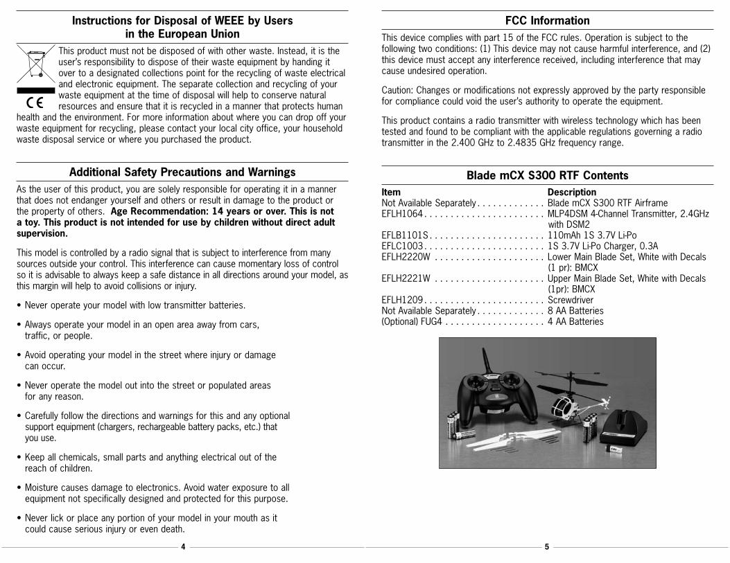
Control TestTurn the transmitter on first and lower the throttle stick completely. Then, plug the battery into the battery lead of the 5-in-1 unit.
Note: The connectors on the battery and battery lead are keyed to prevent reverse polarity connection. However, if you force them together in the wrong orientation and with the wrong polarity, it is still possible to damage the battery and/or 5-in-1 unit. To help further prevent a reverse polarity connection, one side of the endcap on the battery and the connector on the battery lead of the 5-in-1 unit will have a red dot. The connectors are oriented for a proper polarity connection when the red dots are on the same side (usually toward the top of the helicopter).
Mode 2
Mode 1
Position the helicopter to view it from the right-hand side. Move the right-hand stick on the transmitter forward and aft to check elevator pitch control. When the stick is pushed forward, the right-hand servo (when viewing the helicopter from behind) should pull the swashplate downward.
Mode 1
Mode 2
With the stick pulled back, the right-hand servo should push the swashplate upward.
Mode 1
Mode 2
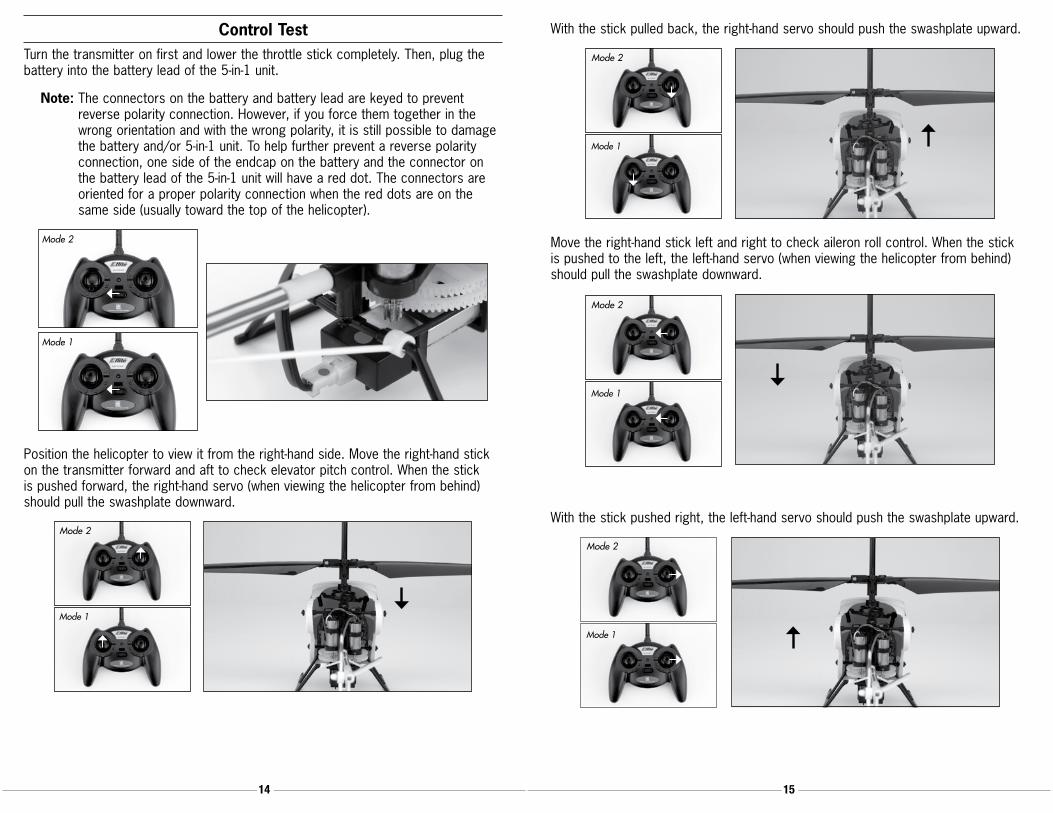
Move the right-hand stick left and right to check aileron roll control. When the stick is pushed to the left, the left-hand servo (when viewing the helicopter from behind) should pull the swashplate downward.
Mode 1
Mode 2
With the stick pushed right, the left-hand servo should push the swashplate upward.
Mode 1
Mode 2

16 1716 17
If at any time during the test the controls respond in the opposite direction, it may be necessary to reverse/change the direction of operation of the flight controls. Follow these steps to change the direction of the various flight controls:
•Becertainthatthebatteryisdisconnectedfromthebatteryleadofthe5-in-1control unit and the transmitter is turned off.
•Pushdownontheappropriatedigitaltrimbuttononthetransmitterforthecontrolyou would like to change the direction of. For example:
Top elevator trim button—elevator channel normal Bottom elevator trim button—elevator channel reversed Left aileron trim button—aileron channel normal Right aileron trim button—aileron channel reversed
•Continuetoholdtheappropriatetrimbuttonwhileturningthetransmitteron.
•Holdthedigitaltrimbuttondownforapproximatelyfiveseconds,untilaseriesofbeeps/tones are heard confirming the selection.
•Connectthebatterytothe5-in-1andcompletetheflightcontroltest,confirmingthat all controls are operating in the correct directions.
If you decide to use an E-flite LP5DSM or HP6DSM transmitter, please position your channel reversal dip switches as follows:
LP5DSM Transmitter HP6DSM Transmitter
Note: Keep a record of the existing settings in case you want to go back and fly
your other aircraft.
Once you’ve reconfirmed the flight control directions, all controls should be functioning properly. However, if you continue to encounter any problems with your Blade mCX S300 responding properly to the transmitter, do not fly. Call the Horizon Support Team at 1-877-504-0233.
5-in-1 Control Unit Description, Arming and Motor Control TestThe unique 5-in-1 Control Unit installed on your Blade mCX S300 is a lightweight combination of main motor electronic speed controls, mixer, gyro, servos and Spektrum DSM2 compatible receiver. The 5-in-1 unit is also equipped with a status indicator LED.
The following checklist contains the steps you must follow to ensure proper arming and operation of the 5-in-1 unit, as well as proper motor response.
• Each time before you fly you should ALWAYS turn the transmitter on before connecting the flight battery to the 5-in-1 unit. Never connect the flight battery to the 5-in-1 unit before powering the transmitter on first. After each flight, be sure that you always disconnect the flight battery from the 5-in-1 unit before powering the transmitter off.
Note: The only time you should connect the flight battery to the 5-in-1 unit before powering the transmitter on is when you are binding the receiver of the 5-in-1 unit to the transmitter. Please see the Transmitter and Receiver Binding section of this manual for more information.
• The throttle stick MUST be set in the lowest possible position, and the throttle trim must be set to the middle or a lower-than-middle position (the middle position is indicated by a longer-than-usual beep/tone), in order for the 5-in-1 unit to arm.

18 1918 19
If this is the first test flight, or a test flight following repairs, you should also center the rudder, aileron and elevator trims.
Set throttle stick at lowest
possible position.
Set throttle stick at lowest
possible position.
Aileron Trim Buttons
Elevator Trim ButtonsThrottle Trim Buttons
Rudder Trim Buttons Aileron Trim Buttons
Throttle Trim ButtonsElevator Trim Buttons
Rudder Trim Buttons
Mode 2 Mode 1
•AfterconfirmingthatthetransmitterhasbeenturnedonandthattheLEDisglowing solid red, it is now safe to connect the flight battery to the 5-in-1 unit.
• With battery power applied to the 5-in-1 unit, the status indicator LED should glow solid red, then blink, then become solid red again.
Note: It is extremely important that you do not move or sway the helicopter once the LED begins to blink confirming that the initialization process and calibration of the gyro has begun. If you do move the helicopter while the LED is blinking, disconnect the flight battery from the 5-in-1 unit and repeat the initialization process.
•WhenthestatusLEDbecomessolidred,the5-in-1unitisinitializedandreadyforflight. Also, as long as the throttle stick and trim are set to the correct positions during the initialization process, the ESCs/motors will now be armed. Use caution as both rotor blades will now spin with throttle stick input.
Note: If the status LED does not become solid red, please review the following.
•IfafterblinkingredthestatusLEDbecomessolidred,butyouhavenocontrolofthe motors, you have a positive Radio Frequency (RF) link between the transmitter and receiver, but the throttle stick and throttle trim may not be set to the correct positions. Check to be sure that the throttle stick is in the lowest possible position and that the throttle trim is set to the middle or a lower-than-middle position. If you now have control of the motors, proceed to the next step of the checklist.
•IfafterblinkingredthestatusLEDturnsoffcompletely,youdonothaveapositiveRF link between the transmitter and receiver. Check to be sure that the transmitter
has been powered on and that the LED indicator on the transmitter is glowing solid red. If the transmitter is powered on and functioning properly, disconnect the flight battery from the 5-in-1 unit, then reconnect it. Now the 5-in-1 unit should initialize and arm properly.
If your 5-in-1 unit will not initialize and arm after following the guidelines as listed above, call the Horizon Support Team at 1-877-504-0233.
• Once you have placed the helicopter in a safe area, free of obstructions, and are clear of the rotor blades, you can safely begin to power up the model to check for proper operation of the motors.
•Advancethethrottlestickupwardslowly,justuntilbothrotorbladesbegintospin. DO NOT attempt to fly the helicopter at this time. Note the direction that each of the rotor blades spins. When viewed from the top, the upper main rotor blades should spin counterclockwise and the lower main rotor blades should spin clockwise. If either set of rotor blades is operating in the wrong direction, disconnect the battery and reverse the polarity of the corresponding motor’s input power leads.
•Afterconfirmingthatthedirectionofrotationforbothrotorbladesiscorrect,itisbest to confirm that both rotor blades respond properly to rudder control inputs.
With the rotor blades spinning at a low level of power, move the rudder (left-hand) stick all the way to the right. This should cause the speed of the upper main rotor blade to increase, and the speed of the lower main rotor blade to decrease.
Next, move the rudder stick all the way to the left. This should cause the speed of the lower main rotor blade to increase and the speed of the upper main rotor blade to decrease. If both rotor blades are not responding properly to rudder input, simply reverse the locations of their motor plugs on the 5-in-1 unit.
After confirming that both rotor blades are rotating in the correct directions, and are responding properly to rudder inputs, your Blade mCX S300 is ready for flight. However, please be sure to review the following sections of the manual BEFORE proceeding with the first flight.

20 2120 21
Understanding the Primary Flight ControlsIf you are not familiar with the controls of your Blade mCX S300, please take a few minutes to familiarize yourself with them before attempting your first flight.
When the throttle stick is in the lowest possible position and throttle trim is set to the middle or a lower-than-middle position, the main rotor blades will not spin. Advancing the stick upward will increase the speed of the main rotor blades. Increasing the speed of the main rotor blades will cause the model to climb.
Mode 1
Mode 2Climb
Decreasing the speed of the main rotor blades by lowering the left-hand stick will cause the model to descend.
Mode 1
Mode 2Descend
After lifting the model off the ground you can balance the throttle by carefully moving the throttle stick up and down so the model will hold a stationary hover without climbing or descending.
Moving the left-hand stick to the left will turn (yaw) the nose of the helicopter to the left about the axis of the main shaft. This is accomplished by increasing the speed of the lower main rotor blade while decreasing the speed of the upper main rotor blade.
Mode 1
Mode 2 Nose Yaw Left
Moving the left-hand stick to the right will turn (yaw) the nose of the helicopter to the right about the axis of the main shaft. This is accomplished by increasing the speed of the upper main rotor blade while decreasing the speed of the lower main rotor blade.
Mode 1
Mode 2 Nose Yaw Right
The rudder trim can be used to help keep the nose of the helicopter from rotating to the left or right when in hover with no rudder stick input. For example, if the nose of the helicopter drifts to the right when in hover, add left rudder trim (by pressing the left-hand rudder trim button) until the nose stays as close to straight as possible.
22 2322 23
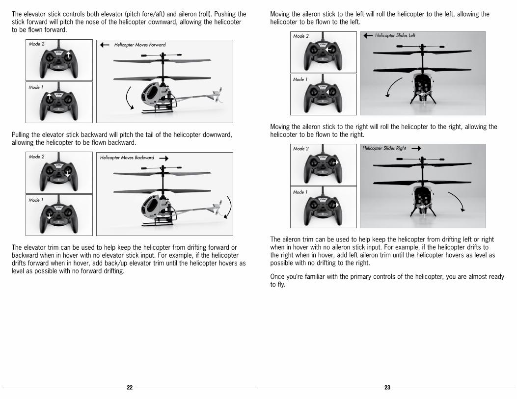
The elevator stick controls both elevator (pitch fore/aft) and aileron (roll). Pushing the stick forward will pitch the nose of the helicopter downward, allowing the helicopter to be flown forward.
Mode 1
Mode 2 Helicopter Moves Forward
Pulling the elevator stick backward will pitch the tail of the helicopter downward, allowing the helicopter to be flown backward.
Mode 1
Mode 2 Helicopter Moves Backward
The elevator trim can be used to help keep the helicopter from drifting forward or backward when in hover with no elevator stick input. For example, if the helicopter drifts forward when in hover, add back/up elevator trim until the helicopter hovers as level as possible with no forward drifting.
Moving the aileron stick to the left will roll the helicopter to the left, allowing the helicopter to be flown to the left.
Mode 1
Mode 2 Helicopter Slides Left
Moving the aileron stick to the right will roll the helicopter to the right, allowing the helicopter to be flown to the right.
Mode 1
Mode 2 Helicopter Slides Right
The aileron trim can be used to help keep the helicopter from drifting left or right when in hover with no aileron stick input. For example, if the helicopter drifts to the right when in hover, add left aileron trim until the helicopter hovers as level as possible with no drifting to the right.
Once you’re familiar with the primary controls of the helicopter, you are almost ready to fly.
24 2524 25
Dual RatesThe MLP4DSM transmitter included with your Blade mCX S300 is equipped with a dual rate feature. This feature allows the pilot to toggle between the high and lowcontrolratesavailablefortheaileron,elevatorandrudderchannels.Youcantoggle between the high and low rates by pushing in on the right-hand stick on the transmitter (while the transmitter is powered on).
Whenthetransmitterisfirstpoweredonitwillbeinthehigh-ratemode.Youcantellyou are in the high-rate mode when the LED on the transmitter glows solid red. In the high-rate mode the controls are allowed to reach their maximum values, which is typically preferred by experienced pilots interested most in maximum control authority.
By pushing in on the right-hand stick while in the high-rate mode, you can enter thelow-ratemode.Youcantellyouareinthelow-ratemodewhentheLEDonthetransmitter blinks continuously. The low-rate mode is typically preferred by (and best for) first-time, low-time and other pilots interested most in a reduced amount of control that allows for smoother and more easily controlled hovering and flying.
Note: The throttle curve in the low-rate mode is also different than it is in the high-rate mode. This makes it much smoother and easier to control the throttle when in the low-rate mode.
Choosing a Flying AreaWhen you are ready for your first flight, you will want to select a relatively open indoor area that is free of people and obstructions. And while it is possible for experienced pilots to fly the Blade mCX S300 in relatively small indoor areas with great success due to its size and controllability, we strongly recommend an area with at least 10-feet by 10-feet of floor space and no less than 8-foot ceilings when making your first few flights.
Once you have properly trimmed your helicopter and become familiar with its handling and capabilities, you will be able to fly in other smaller, less open areas.
Note: The Blade mCX S300 is designed and intended to be flown INDOORS ONLY.
Flying the Blade mCX S300Having followed the proper 5-in-1 control unit initialization and arming procedures, confirmed proper control of the servos and motors, and found a suitable flying area, your Blade mCX S300 is ready for flight.
Note: In addition to reviewing the flight maneuvers outlined below, we recommend that you watch the Instructional Video located on the product page for the Blade mCX S300 on www.horizonhobby.com to see many of these maneuvers and adjustments performed by the helicopter and pilot.
•Slowlyraisethethrottlestick,increasingthespeedofthemainrotorbladesuntilthe model begins to lift off. Do not raise the throttle stick too quickly as the model could climb too fast causing you to lose control or make contact with objects above.
•Liftthemodeloffthegroundjustafewinchesandconcentrateonbalancingthethrottle stick position so that the model holds a steady hover altitude. In some cases it may be best to make a few short “hops” to an altitude of just a few inches until you become familiar with the control inputs and trim settings required to maintain a steady hover and altitude.
As you will find, the Blade mCX S300 requires minor throttle adjustments to maintain its altitude in hover. Remember to keep these throttle adjustments as minimal as possible as large adjustments could result in a loss of control and/or a possible crash.
•Whileattemptingtoestablishalow-levelhover,youcanalsochecktoseeifanytrim adjustments are required to help keep the Blade mCX S300 from constantly drifting in various directions. If you find the helicopter constantly drifts without any directional control input, it will be best to land the model before making any adjustments to the trim settings. Additional details regarding the location and function of the trim buttons can be found in the “Understanding the Primary Flight Controls” section of this manual.
If the nose of the helicopter is drifting to the left or right, you will need to adjust the rudder trim.
If the helicopter is drifting forward or backward, you will need to adjust the elevator trim.
If the helicopter is drifting to the left or right, you will need to adjust the aileron trim.
Continue to make trim adjustments until the helicopter can hover at a low altitude with very little drifting and directional control input. If the Blade mCX S300 is your first helicopter model, it may be best to have the help of an experienced helicopter pilot to trim the model for you before making your first flight.

26 2726 27
•OnceyouhavetheBlademCXS300properlytrimmedandmaintainingastablelow-level hover, practice using the rudder, elevator and aileron controls to get a feel for how the helicopter responds to control inputs. Remember to keep the control inputs as minimal as possible to prevent over-controlling the helicopter, especially when in hover.
After becoming comfortable with hovering the Blade mCX S300 at low-levels of altitude just a few inches off the ground, you can transition to hovering and flying the helicopter at higher altitudes of approximately three to four feet. At these higher altitudes you will be able to get a feel for the flight characteristics of the Blade mCX S300 when it is flying out of “ground effect.”
•Ifatanytimeduringflightyoufeellikethehelicopterisdriftingoutofcontrol,simplyreleaseallofthecontrolsexceptforthrottle.Youwillneedtousethethrottle to maintain altitude, but due to the inherent stability of the coaxial, counter-rotating blade design, the Blade mCX S300 will simply return to a stable hover on its own if space allows.
•Don’tbeafraidtosetthehelicopterdownonthegroundquicklybyloweringthethrottle when approaching walls or other obstacles to help prevent main rotor blade strikes.
• IN THE UNFORTUNATE EVENT OF A CRASH OR ROTOR BLADE STRIKE, NO MATTER HOW MINOR OR MAJOR, YOU MUST LOWER THE THROTTLE STICK TO THE LOWEST POSSIBLE POSITION AS QUICKLY AS POSSIBLE TO PREVENT DAMAGE TO THE ESCS OF THE 5-IN-1 UNIT. YOU MUST ALSO BE SURE THAT THE THROTTLE TRIM IS SET TO THE MIDDLE POSITION OR TO A POSITION THAT IS LOWER THAN THE MIDDLE.
Failure to lower the throttle stick to the lowest possible position in the event of a crash could result in damage to the ESCs in the 5-in-1 unit, which may require replacement of the 5-in-1 unit.
Note: Crash damage is not covered under the warranty.
•OnceyouhavegainedexperienceandconfidenceinhoveringtheBlademCXS300, you can attempt more advanced maneuvers including:
Forward Flight Skidding Takeoffs
Backward Flight Skidding Landings
Pirouettes Spot Landings
Transmitter and Receiver BindingBinding is the process of programming the receiver to recognize the GUID (Globally Unique Identifier) code of a single specific transmitter. If you ever find it is necessary to replace the transmitter or the receiver/5-in-1 unit for your model, it will be necessary for you to ‘bind’ the new transmitter or receiver/5-in-1 to your existing transmitter or receiver/5-in-1 for proper operation.
The following steps outline the binding process:
•Makesuretheflightbatteryisdisconnectedfromthe5-in-1unitandthetransmitteris turned off.
•Plugtheflightbatteryintothe5-in-1unit.After5secondstheLEDonthe5-in1unitwill begin flashing.
•PUSHdirectlydownontheleft-handstickwhileswitchingthetransmitteron(youwill feel a ‘click’ when you push in on the end of the stick).
•Ifyouenteredbindmodecorrectly,youwillhearaseriesofbeepsfromthetransmitter and see the LED on the transmitter blink.
•YouwillseeasolidLEDapproximately5-10secondslateronthereceiver/5-in-1.Youshouldnowbeboundtothetransmitter,andhavefullcontrolandfunction.
If you encounter any problems, repeat the binding process again or call the Horizon Support Team at 1-877-504-0233.
28 2928 29
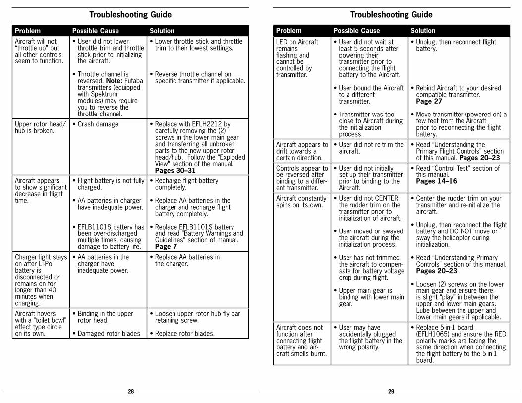
Troubleshooting Guide Troubleshooting Guide
Problem Possible Cause SolutionAircraft will not “throttle up” but all other controls seem to function.
•Userdidnotlowerthrottle trim and throttle stick prior to initializing the aircraft.
•Throttlechannelisreversed. Note: Futaba transmitters (equipped with Spektrum modules) may require you to reverse the throttle channel.
•Lowerthrottlestickandthrottletrim to their lowest settings.
•Reversethrottlechannelon specific transmitter if applicable.
Upper rotor head/hub is broken.
•Crashdamage •ReplacewithEFLH2212by carefully removing the (2) screws in the lower main gear and transferring all unbroken parts to the new upper rotor head/hub. Follow the “Exploded View” section of the manual. Pages 30–31
Aircraft appears to show significant decrease in flight time.
•Flightbatteryisnotfullycharged.
•AAbatteriesinchargerhave inadequate power.
•EFLB1101Sbatteryhasbeen over-discharged multiple times, causing damage to battery life.
•Rechargeflightbattery completely.
•ReplaceAAbatteriesinthe charger and recharge flight battery completely.
•ReplaceEFLB1101Sbatteryand read “Battery Warnings and Guidelines” section of manual. Page 7
Charger light stays on after Li-Po battery is disconnected or remains on for longer than 40 minutes when charging.
•AAbatteriesinthe charger have inadequate power.
•ReplaceAAbatteriesin the charger.
Aircraft hovers with a “toilet bowl” effect type circle on its own.
•Bindingintheupperrotor head.
•Damagedrotorblades
•Loosenupperrotorhubflybarretaining screw.
•Replacerotorblades.
Problem Possible Cause Solution
LED on Aircraft remains flashing and cannot be controlled by transmitter.
•Userdidnotwaitatleast 5 seconds after powering their transmitter prior to connecting the flight battery to the Aircraft.
•UserboundtheAircraftto a different transmitter.
•Transmitterwastooclose to Aircraft during the initialization process.
•Unplug,thenreconnectflight battery.
•RebindAircrafttoyourdesiredcompatible transmitter. Page 27
•Movetransmitter(poweredon)afew feet from the Aircraft prior to reconnecting the flight battery.
Aircraft appears to drift towards a certain direction.
•Userdidnotre-trimtheaircraft.
•Read“UnderstandingthePrimary Flight Controls” section of this manual. Pages 20–23
Controls appear to be reversed after binding to a differ-ent transmitter.
•Userdidnotinitiallyset up their transmitter prior to binding to the Aircraft.
•Read“ControlTest”sectionofthis manual. Pages 14–16
Aircraft constantly spins on its own.
•UserdidnotCENTERthe rudder trim on the transmitter prior to initialization of aircraft.
•Usermovedorswayedthe aircraft during the initialization process.
•Userhasnottrimmedthe aircraft to compen-sate for battery voltage drop during flight.
•Uppermaingearisbinding with lower main gear.
•Centertheruddertrimonyourtransmitter and re-initialize the aircraft.
•Unplug,thenreconnecttheflightbattery and DO NOT move or sway the helicopter during initialization.
•Read“UnderstandingPrimaryControls” section of this manual. Pages 20–23
•Loosen(2)screwsonthelowermain gear and ensure there is slight “play” in between the upper and lower main gears. Lube between the upper and lower main gears if applicable.
Aircraft does not function after connecting flight battery and air-craft smells burnt.
•Usermayhave accidentally plugged the flight battery in the wrong polarity.
•Replace5-in-1board(EFLH1065) and ensure the RED polarity marks are facing the same direction when connecting the flight battery to the 5-in-1 board.

30 3130 31
Exploded View Parts ListingReference # Description (Quantity Requested) Item #001 Stabilizer Flybar Paddle (2) EFLH2219002 Stabilizer Flybar Seesaw (1) EFLH2219003 Stabilizer Flybar (1) EFLH2219004 Upper Rotor Head & Stabilizer Flybar Hub/Holder (1) EFLH2212005 Upper Rotor Blade (2) EFLH2221006 Bushing (2) EFLH2213007 Stabilizer Flybar Linkage (1) EFLH2219008 Screw T1.2x5mm (7) EFLH2225009 Inner Shaft (1) EFLH2212010 Bushing Holder (1) EFLH2213011 Lower Main Blade (2) EFLH2220012 Outer Shaft (1) EFLH2213013 Lower Rotor Head (1) EFLH2217014 Screw M1.2x2mm (3) EFLH2225015 Upper Swashplate (1) EFLH2216016 Bearing 6x10x2.5mm (1) EFLH2216017 Lower Swashplate (1) EFLH2216018 Main Motor, Right (1) EFLH2210019 Main Motor, Left (1) EFLH2209020 Outer Shaft Retaining Collar (1) EFLH2214021 Servo Pushrod Control Link (2) EFLH2218022 Servo Pushrod (2) EFLH2218023 Main Frame (1) EFLH2224024 Replacement Servo Mechanics (2): BMCX EFLH1066025 5-in-1 Control Unit (1) EFLH1065026 Insulating Washer (2) EFLH2225027 Screw M0.8x2.5mm (8) EFLH2225028 S300 Body/Canopy, w/ Decals: BMCX EFLH2327029 Inner Shaft Main Gear (1) EFLH2211030 Inner Shaft Main Gear Retaining Collar (1) EFLH2211031 S300 Landing Skid & Battery Mount: BMCX EFLH2322032 Screw M1.2x2.5mm (1) EFLH2225033 Battery (1) EFLB1101S034 Outer Shaft Main Gear (1) EFLH2213035 Outer Shaft Bearing 3x6x2mm (2) EFLH2215036 O-Ring (8) EFLH2226037 S300 Canopy/Body Mount Extension (2) EFLH2327038 Pinion Gear (2) EFLH2209 EFLH2210039 Tail Boom and Angle Adapter (1) EFLH2323040 Lower Rotor Head/Swash Linkage (2) EFLH2217041 Tail Boom and Angle Adapter (1) EFLH2323042 S300 Tail Boom Accent Set EFLH2324043 S300 Tail Rotor and Fin Set EFLH2328
Exploded View
024
012
009
001
043
042
041
038
039
037
036
035
034
032
033
006
015
031
030
029
027028
026025
023 022
021
020
019
018
017016
011 014
013
010
040
008
007005
004
003
002

32 3332 33
Replacement Parts ListEFLB1101S . . . . . . . . . . 110mAh 1S 3.7V Li-Po: BMCXEFLC1003 . . . . . . . . . . . 1S 3.7V Li-Po Charger, 0.3A: BMCXEFLH1064 . . . . . . . . . . .MLP4DSM 4-Channel Transmitter, 2.4GHz: BMCXEFLH1065 . . . . . . . . . . . 5-in-1 Control Unit, Rx/Servos/ESCs/Mixer/Gyro: BMCXEFLH1066 . . . . . . . . . . . Replacement Servo Mechanics (2): BMCXEFLH2209 . . . . . . . . . . .Motor w/Pinion, Left: BMCXEFLH2210 . . . . . . . . . . .Motor w/Pinion, Right: BMCXEFLH2211 . . . . . . . . . . . Inner Shaft Main Gear: BMCXEFLH2212 . . . . . . . . . . . Inner Shaft w/Head/Hub: BMCXEFLH2213 . . . . . . . . . . . Outer Shaft, Main Gear and Bushing Holder Set: BMCXEFLH2214 . . . . . . . . . . . Outer Shaft Retaining Collar Set: BMCXEFLH2215 . . . . . . . . . . . Outer Shaft Bearing, 3x6x2mm (2): BMCXEFLH2216 . . . . . . . . . . . Swashplate Set: BMCXEFLH2217 . . . . . . . . . . . Lower Rotor Head & Linkage Set: BMCXEFLH2218 . . . . . . . . . . . Servo Pushrod Set: BMCXEFLH2219 . . . . . . . . . . . Stabilizer Flybar Set: BMCXEFLH2220 . . . . . . . . . . . Lower Main Blade Set (1 pair): BMCXEFLH2221 . . . . . . . . . . . Upper Main Blade Set (1 pair): BMCXEFLH2322 . . . . . . . . . . . S300 Landing Skid and Battery Mount: BMCX EFLH2323 . . . . . . . . . . . S300 Tail Boom and Angle Adapter: BMCX EFLH2224 . . . . . . . . . . .Main Frame Set: BMCXEFLH2225 . . . . . . . . . . . Hardware Set: BMCXEFLH2226 . . . . . . . . . . . Body/Canopy Mounting O-Ring (8): BMCXEFLH2327 . . . . . . . . . . . S300 Body/Canopy, w/ Decals: BMCXEFLH2328 . . . . . . . . . . . S300 Tail Rotor and Fin Set: BMCX EFLH2324 . . . . . . . . . . . S300 Tail Boom Accent Set: BMCX
Option Parts ListEFLH2216GL . . . . . . . . . Swashplate Set, Glow in the Dark: BMCXEFLH2220GL . . . . . . . . . Lower Main Blade Set, Glow in the Dark (1 pr): BMCXEFLH2220W . . . . . . . . . Lower Main Blade Set, White with Decals (1pr): BMCXEFLH2221GL . . . . . . . . . Upper Main Blade Set, Glow in the Dark (1 pr): BMCXEFLH2221W . . . . . . . . . Upper Main Blade Set, White with Decals (1pr): BMCXEFLH2222GL . . . . . . . . . Landing Skid & Batt Mnt Set, Glow in the Dark: BMCXEFLH2224GL . . . . . . . . .Main Frame Set, Glow in the Dark: BMCXEFLH2227W . . . . . . . . . Body/Canopy, White without Decals: BMCXEFLH2228GL . . . . . . . . . Vertical Fin, Glow in the Dark without Decals: BMCXEFLH2228W . . . . . . . . . Vertical Fin, White without Decals: BMCXEFLH2230 . . . . . . . . . . . Decal Sheet, Blue/Silver Graphics: BMCXEFLC1004 . . . . . . . . . . . 4-port ChargerEFLC1005 . . . . . . . . . . . 6V Power Supply (For 4-port Charger)
Warranty PeriodHorizon Hobby, Inc., (Horizon) warranties that the Products purchased (the “Product”) will be free from defects in materials and workmanship at the date of purchase by the Purchaser.
Limited Warranty(a) This warranty is limited to the original Purchaser (“Purchaser”) and is not transferable.REPAIRORREPLACEMENTASPROVIDEDUNDERTHISWARRANTYISTHEEXCLUSIVEREMEDYOFTHEPURCHASER.ThiswarrantycoversonlythoseProducts purchased from an authorized Horizon dealer. Third party transactions are not covered by this warranty. Proof of purchase is required for warranty claims. Further, Horizon reserves the right to change or modify this warranty without notice and disclaims all other warranties, express or implied.
(b)Limitations-HORIZONMAKESNOWARRANTYORREPRESENTATION,EXPRESSORIMPLIED,ABOUTNON-INFRINGEMENT,MERCHANTABILITYORFITNESSFORAPARTICULAR PURPOSE OF THE PRODUCT. THE PURCHASER ACKNOWLEDGES THAT THEYALONEHAVEDETERMINEDTHATTHEPRODUCTWILLSUITABLYMEETTHEREQUIREMENTS OF THE PURCHASER’S INTENDED USE.
(c) Purchaser Remedy- Horizon’s sole obligation hereunder shall be that Horizon will, at its option, (i) repair or (ii) replace, any Product determined by Horizon to be defective. In the event of a defect, these are the Purchaser’s exclusive remedies. Horizon reserves the right to inspect any and all equipment involved in a warranty claim. Repair or replacement decisions are at the sole discretion of Horizon. This warranty does not cover cosmetic damage or damage due to acts of God, accident, misuse, abuse, negligence, commercial use, or modification of or to any part of the Product. This warranty does not cover damage due to improper installation, operation, maintenance, or attempted repair by anyone other than Horizon. Return of any goods by Purchaser must be approved by Horizon before shipment.
Damage LimitsHORIZON SHALL NOT BE LIABLE FOR SPECIAL, INDIRECT OR CONSEQUENTIAL DAMAGES,LOSSOFPROFITSORPRODUCTIONORCOMMERCIALLOSSINANYWAYCONNECTED WITH THE PRODUCT, WHETHER SUCH CLAIM IS BASED IN CONTRACT, WARRANTY,NEGLIGENCE,ORSTRICTLIABILITY.Further,innoeventshalltheliabilityof Horizon exceed the individual price of the Product on which liability is asserted. As Horizon has no control over use, setup, final assembly, modification or misuse, no liability shall be assumed nor accepted for any resulting damage or injury. By the act of use, setup or assembly, the user accepts all resulting liability.
If you as the Purchaser or user are not prepared to accept the liability associated with the use of this Product, you are advised to return this Product immediately in new and unused condition to the place of purchase.
34 3534 35
Law: These Terms are governed by Illinois law (without regard to conflict of law principals).
Safety PrecautionsThis is a sophisticated hobby Product and not a toy. It must be operated with caution and common sense and requires some basic mechanical ability. Failure to operate this Product in a safe and responsible manner could result in injury or damage to the Product or other property. This Product is not intended for use by children without direct adult supervision. The Product manual contains instructions for safety, operation and maintenance. It is essential to read and follow all the instructions and warnings in the manual, prior to assembly, setup or use, in order to operate correctly and avoid damage or injury.
Questions, Assistance and RepairsYourlocalhobbystoreand/orplaceofpurchasecannotprovidewarrantysupportor repair. Once assembly, setup or use of the Product has been started, you must contact Horizon directly. This will enable Horizon to better answer your questions and service you in the event that you may need any assistance. For questions or assistance, please direct your email to [email protected], or call 877.504.0233 toll free to speak to a service technician.
Inspections or RepairsIf this Product needs to be inspected or repaired, please call for a Return Merchandise Authorization (RMA). Pack the Product securely using a shipping carton. Please note that original boxes may be included, but are not designed to withstand the rigors of shipping without additional protection. Ship via a carrier that provides tracking and insurance for lost or damaged parcels, as Horizon is not responsible for merchandise until it arrives and is accepted at our facility. A Service Repair Request is available at www.horizonhobby.com on the “Support” tab. If you do not have internet access, please include a letter with your complete name, street address, email address and phone number where you can be reached during business days, your RMA number, a list of the included items, method of payment for any non-warrantyexpensesandabriefsummaryoftheproblem.Youroriginalsalesreceiptmust also be included for warranty consideration. Be sure your name, address, and RMA number are clearly written on the outside of the shipping carton.
Warranty Inspection and RepairsTo receive warranty service, you must include your original sales receipt verifying the proof-of-purchase date. Provided warranty conditions have been met, your Product will be repaired or replaced free of charge. Repair or replacement decisions are at the sole discretion of Horizon Hobby.
Non-Warranty RepairsShould your repair not be covered by warranty the repair will be completed and payment will be required without notification or estimate of the expense unless the expense exceeds 50% of the retail purchase cost. By submitting the item for repair you are agreeing to payment of the repair without notification. Repair estimates are availableuponrequest.Youmustincludethisrequestwithyourrepair.Non-warrantyrepair estimates will be billed a minimum of ½ hour of labor. In addition you will be billed for return freight. Please advise us of your preferred method of payment. Horizon accepts money orders and cashiers checks, as well as Visa, MasterCard, American Express, and Discover cards. If you choose to pay by credit card, please include your credit card number and expiration date. Any repair left unpaid or unclaimed after 90 days will be considered abandoned and will be disposed of accordingly. Please note: non-warranty repair is only available on electronics and model engines.
United States Electronics and engines requiring inspection or repair should be shipped to the following address:
Horizon Service Center 4105 Fieldstone Road
Champaign, Illinois 61822
All other Products requiring warranty inspection or repair should be shipped to the following address:
Horizon Product Support 4105 Fieldstone Road
Champaign, Illinois 61822
Please call 877-504-0233 or e-mail us at [email protected] with any questions or concerns regarding this product or warranty.
European Union Electronics and engines requiring inspection or repair should be shipped to the following address:
Horizon Hobby UK Units 1-4 Ployters Rd
Staple Tye Harlow, Essex
CM18 7NS United Kingdom
Please call +44 (0) 1279 641 097 or e-mail us at [email protected] with any questions or concerns regarding this product or warranty.

36 3736 37
Electronics and engines requiring inspection or repair should be shipped to the following address:
Horizon Technischer Service Hamburger Strasse 10
25335 Elmshorn Germany
Please call +49 4121 46199 66 or e-mail us at [email protected] with any questions or concerns regarding this product or warranty.
Product RegistrationRegistering your product will provide you the option to stay up-to-date on product information, new products, customization options and other information for E-flite owners. Register your product today for your chance to win great E-flite products. Visit www.E-fliteRC.com/register/ for terms and conditions of the sweepstakes or to register your product today. Sweepstakes open to residents of the 50 United States, Puerto Rico or Virgin Islands. Must be 18 years of age or older to win.
Declaration of Conformity(in accordance with ISO/IEC 17050-1)
No. HH2008121801
Product(s): Blade mCX S300 Item Number(s): EFLH2300, EFLH2380 Equipment class: 1
The object of declaration described above is in conformity with the requirements of the specifications listed below, following the provisions of the European R&TTE directive 1999/5/EC:
EN 300-328 Technical requirements for Radio equipment EN 301 489-1, 301 489-17 General EMC requirements for Radio
equipmentEN 60950 Safety
Signed for and on behalf of: Horizon Hobby, Inc. Champaign, IL USA Dec 18, 2008
Steven A. Hall Vice President International Operations and Risk Management Horizon Hobby, Inc.

38 3938 39