Embed Size (px)
Citation preview

Proceedings World Geothermal Congress 2010 Bali, Indonesia, 25-29 April 2010
1
Design and Experimental Validation of Heat Exchangers Equipment for 2 kW Model of Binary Cycle Power Plant
Bambang Teguh P1., Himawan S.1, Suyanto, Taufan S.2, MD Trisno3 1BTMP-BPPT, 230 building, Puspiptek, Serpong – Tangerang, 15314, Indonesia
2PTKKE, BPPT building, Tour II, Floor 20, Jl. MH. Thamrin, No. 8. Jakarta 3Lecturer in Mech. Engineering Dept.- ISTN-Jakarta
[email protected], [email protected]
Keywords: geothermal, binary cycle, n-pentane, thermal waste, brine, heat exchangers, turbine
ABSTRACT
Currently, 100% of brine at direct-steam geothermal power plant is injected into injection wells. Injected brine generally has a temperature higher than 100oC and mass flow rate around hundred of ton/hour. The rapid estimation showed the content of rejected energy is around hundred millions of watts. Binary cycle plant may be advantageous technology to recover this energy waste. In order to study the implementation above technology, BPPT has developed the 2 kW model of binary cycle power plant using the thermal energy of brine. In this plant, thermal energy of brine is transferred via a heat exchanger to working fluid for use in a fairly conventional Rankine cycle. The power cycle consists of an evaporator, a turbine-generator, a condenser, and feed pump. Other equipment is cooling tower to serve the condenser cooling water. The working fluid used in this plant is n-pentane to achieve a good thermodynamic match to the particular characteristics of brine, especially brine temperature. This paper presents the design and testing of heat exchangers equipments and n-pentane turbine of this binary cycle plant model. From design analysis the heat exchanger equipment to be used are 56.31 kW shell and tube evaporator, 53.68 kW shell and tube condenser. The turbine design is single-stage impulse turbine with five convergent nozzles, 382.3 mm rotor diameter, 60 blades, 16.5 mm height of blade, and 10 mm width of blade. This turbine is designed to operate at 3000 rpm and 65.6% turbine efficiency. Experimental result showed that the system has successfully produced 1.2 kWe. There is 8.5% different in efficiency lower than design condition The method of design and the result of experiment will be discussed in this paper.
1. INTRODUCTION
1.1 Thermal Waste of Direct Steam Plant
Indonesia has the largest geothermal resources in the world, with a potential of 40% in the world, around 27,000 MW. Indonesia has been focusing on the development of high enthalpy geothermal resources. Geothermal power plants have been operated around 1052 MW in Indonesia that are direct-steam plants type. 100% of separated brine from these plants is reinjected into injection wells. The reinjected brine generally has a temperature higher than 100oC and mass flow rate of hundred ton per hour. Therefore the thermal energy rejected is around hundred million watts. An example for 1×110 MW direct-steam geothermal power plant existing in West Java, rejected brine is around 270 ton/hr at 180oC and 11.0 bar (abs), containing thermal energy around 57.23 MW.
This thermal energy of the brine can be recovered by transferring via a heat exchanger to working fluid for use in other process. In this case, depending on silica content in the brine, minimum temperature drop of brine permitted in heat exchanger is limited by silica scaling formation
Assuming the permitted temperature drop of this brine in heat exchanger is until 140oC, then the thermal energy that can be recovered is about 13 MW thermal.
In the era of energy crisis, this energy waste is very important to be concerned to increase energy saving and efficiency. On the other hand, in Indonesia there are a lot of low-to-medium enthalpy resources which can also be utilized for electricity generation, but they are not developed optimally yet.
1.2 Binary Cycle Plant
Binary cycle plant is an advantageous technology for recovering the energy waste or unusable energy especially at low geo-fluid temperatures (150oC), or geo-fluids with high corrosion and scaling potential. In a binary cycle plant, thermal energy of brine or geo-fluid is transferred through a heat exchanger to working fluid for using in a fairly conventional Rankine cycle. A flow diagram for typical basic binary plant is shown in Figure 1.
Figure 1. Schematic of binary cycle geothermal power-plant Source: http://www.worldenergy.org
The power cycle consists of heat exchangers (pre-heater and evaporator), a set of control valves, a turbine-generator set, a condenser, and feed pump. Either water or air may be used for cooling depending on the applied cooling systems. If the wet cooling system is applied, an independent source of make-up water must be found. Owing to chemical impurities, the waste brine is not suitable for cooling tower make-up.
Teguh et al.
2
The engineering designer must consider a wide range of candidate working fluids for the power cycle. For making the selection, one tries to achieve a good thermodynamic match to the particular characteristics of the geo-fluid, especially the geo-fluid temperature. Among the important properties of candidate working fluids are: critical temperature and pressure, saturation properties (including whether the fluid exhibits retrograde condensation, thermal stability, flammability, toxicity, ozone depletion potential, heat transfer coefficients, speed of sound at turbine exhaust condition, and cost. Hydrocarbons such as isobutane, isopentane, and propane are good candidate working fluids as are certain refrigerants.
The optimal fluid will give high utilization efficiency together with safe and economical operation. Binary plants lend themselves very well to modular packages in the power range of 1 to 3 MW per unit.
In order to study the implementation of binary plant technology, BPPT has developed the 2 kW model of binary cycle power plant using thermal energy of brine. A diagram of this model is shown in Figure 2. The power cycle consists of an evaporator, a turbine-generator, a condenser, and feed pump. Other equipment is a cooling tower to serve the condenser cooling water. Thermal energy of brine is transferred trough a heat exchanger (evaporator) to working fluid. The working fluid of the plant is n-pentane. The paper presents the design and testing of this binary cycle plant model. Experimental validation of this plant was conducted using a small extraction of brine at Wayang Windu geothermal power plant.
Figure 2. Diagram for binary plant using brine as thermal energy resources. Source: Bambang T. Prasetyo (2008)
1.3 Heat Exchangers
Many types of heat exchanger (plates, tubular, etc) can be used as evaporator and condenser. But in this study, shell and tube type is chosen because its has some advantages, for example: very simple geometry, well-established design procedure, can be constructed from a wide range of materials, uses well-established fabrication techniques, easily cleaned, and technicians were familiarized with this technology.
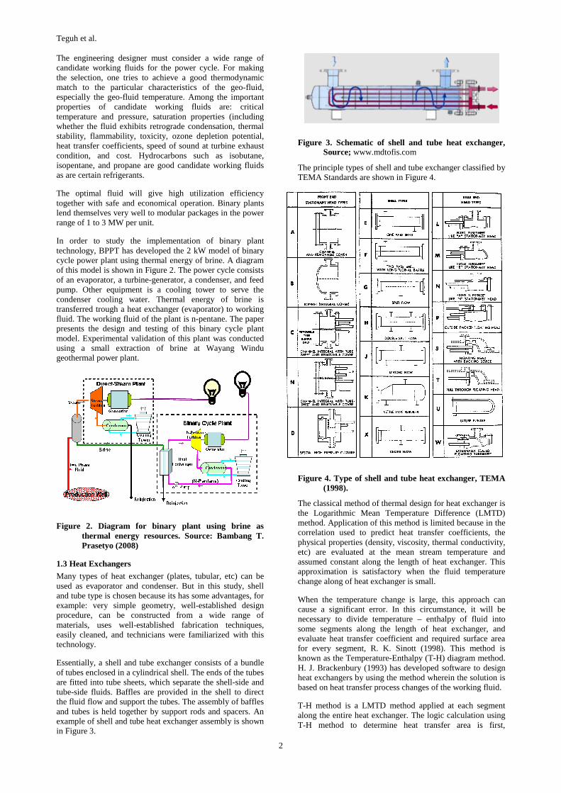
Essentially, a shell and tube exchanger consists of a bundle of tubes enclosed in a cylindrical shell. The ends of the tubes are fitted into tube sheets, which separate the shell-side and tube-side fluids. Baffles are provided in the shell to direct the fluid flow and support the tubes. The assembly of baffles and tubes is held together by support rods and spacers. An example of shell and tube heat exchanger assembly is shown in Figure 3.
Figure 3. Schematic of shell and tube heat exchanger, Source; www.mdtofis.com
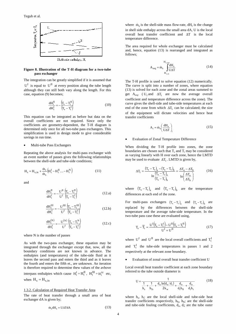
The principle types of shell and tube exchanger classified by TEMA Standards are shown in Figure 4.
Figure 4. Type of shell and tube heat exchanger, TEMA (1998).
The classical method of thermal design for heat exchanger is the Logarithmic Mean Temperature Difference (LMTD) method. Application of this method is limited because in the correlation used to predict heat transfer coefficients, the physical properties (density, viscosity, thermal conductivity, etc) are evaluated at the mean stream temperature and assumed constant along the length of heat exchanger. This approximation is satisfactory when the fluid temperature change along of heat exchanger is small.
When the temperature change is large, this approach can cause a significant error. In this circumstance, it will be necessary to divide temperature – enthalpy of fluid into some segments along the length of heat exchanger, and evaluate heat transfer coefficient and required surface area for every segment, R. K. Sinott (1998). This method is known as the Temperature-Enthalpy (T-H) diagram method. H. J. Brackenbury (1993) has developed software to design heat exchangers by using the method wherein the solution is based on heat transfer process changes of the working fluid.
T-H method is a LMTD method applied at each segment along the entire heat exchanger. The logic calculation using T-H method to determine heat transfer area is first,

Teguh et al.
3
calculation of the T-H profile and second calculation of the heat transfer area.
1.3.1 Calculation of T-H Profile
• Single-tube Pass Exchanger
Figure 5 illustrates the operation of a single pass counter-flow exchanger with flow-rate sm& on the shell side and tm&
on the tube side. A heat balance over area A of the exchanger gives:
( ) ( ) tin,ttsout,ss mHHmHH && −=− (1)
Figure 5. Schematic diagram of a counter-flow, single pass exchanger
Where Hs and Ht are respectively the shell-side and tube-side specific enthalpies and the subscript ‘in’ and ‘out’ refer respectively to the inlet and outlet of the fluid streams. Hence, the tube-side specific enthalpy can be explicitly expressed in the terms of the shell-side enthalpy as follows:
( )out,sst
sin,tt HH
m
mHH −=−
&
& (2)
( )sin,st
sout,tt HH
m
mHH −−=−
&
& (3)
where equation (3) is determined from equation (2) using the following heat balance over the whole exchanger.
( ) ( ) tin,tout,tsout,sin,sT mHHmHHQ &&& −=−= (4)
It is assumed here that the relationship between the temperature and the specific enthalpy is known for each stream. The shell-side temperature, Ts, can therefore be plotted as a function of the shell-side specific enthalpy as illustrated on Figure 6. Using equation (2) or (3) and the tube-side T-H curve, the tube-side temperature, Tt, can also be plotted against Hs as shown in Figure 6. The temperature difference Ts-Tt can therefore be obtained for any value of Hs. It is worth nothing that Figure 6 is independent of heat transfer coefficient and hence of the detailed geometry. In a design, therefore, the diagrams need only be obtained once for all single-pass exchangers.
Figure 6. Illustration of the temperature-enthalpy diagram for single pass counter-flow exchanger
• Two-tube Pass Exchanger
Figure 7 illustrates the operation of two-tube pass exchanger in which the shell-side flow is counter-current to the first pass and co-current to the second.
Figure 7. Schematic diagram of a two-tube pass exchanger
A heat balance over area A of exchanger give;
( ) ( ) tIItout,tin,t
Itsout,ss mHHHHmHH && −+−=− (5)
where ItH and II
tH are the specific enthalpies in pass I and
II respectively. Combining this with the overall balance for the exchanger (equation 4) gives;
( )It
IIt
s
tin,ss HH
m
mHH −−=
&
& (6)
An incremental heat balance over dA for pass I gives;
( )2
dATTUdHm I
tsII
tt −=& (7)
where it is assumed that half the area is in each pass. IU is
the overall coefficient and ItT the temperature for pass I.
Similarly for pass II ;
( )2
dATTUdHm II
tsIIII
tt −=& (8)
Dividing equation (7) by equation (8) gives;
( )( )I
ts
IIts
I
II
It
IIt
TT
TT
U
U
dH
dH
−−−= (9)
Starting with ItH = in,tH when II
tH = out,tH , this equation may
be integrated numerically over the exchanger by using the following other relationships;
a. equation (6) relating the shell-side to the tube-side enthalpies,
b. the T-H curves for each stream, and c. relationships expressing the overall coefficient U
as a function of Ht, Hs and Ts-Tt .
Integration is stopped when ItH = II
tH and the results may be
plotted on a T-H diagram as illustrated in Figure 8
tm&
sm&
out,sH
out,tH
in,sH
in,tHss T,H
tt T,H
A dA
tm&sm&
out,sH
out,tH
in,sH
in,tH
ss T,H
It
It T,H
A dA
IIt
IIt T,H
tm&
Teguh et al.
4
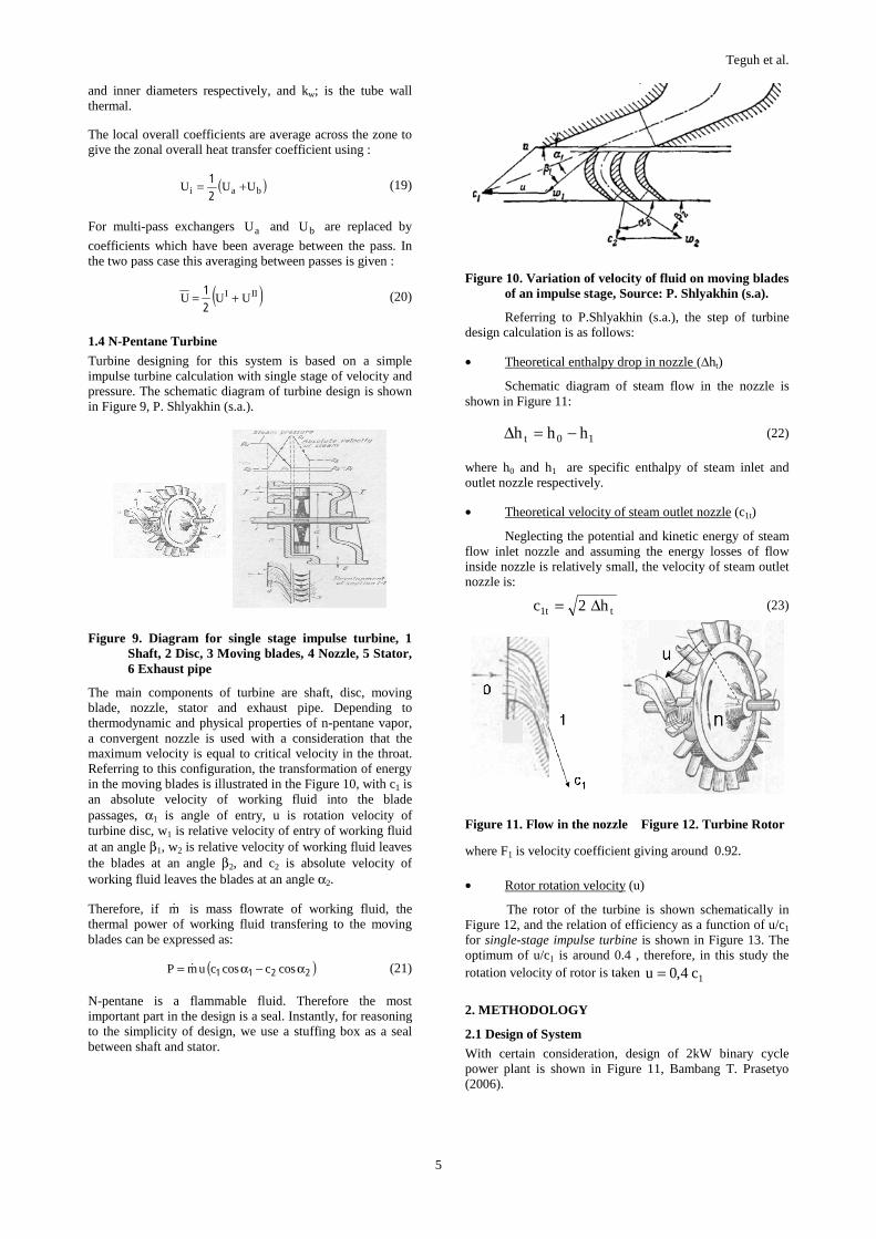
Figure 8. Illustration of the T-H diagram for a two-tube pass exchanger
The integration can be greatly simplified if it is assumed that IU is equal to IIU at every position along the tube length
although they can still both vary along the length. For this case, equation (9) becomes;
( )( )I
ts
IIts
It
IIt
TT
TT
dH
dH
−−
−= (10)
This equation can be integrated as before but data on the overall coefficients are not required. Since only the coefficients are geometry-dependent, the T-H diagram is determined only once for all two-tube pass exchangers. This simplification is used in design mode to give considerable savings in run time.
• Multi-tube Pass Exchangers
Repeating the above analysis for multi-pass exchanger with an event number of passes gives the following relationships between the shell-side and tube-side conditions;
( )Nt
IIt
It
s
tin,ss H....HH
m
mHH −−+=
&
& (11)
and
( )( )I
ts
IIts
I
II
It
IIt
TT
TT
U
U
dH
dH
−−−= (12.a)
( )( )I
ts
IIIts
I
III
It
IIIt
TT
TT
U
U
dH
dH
−−−= (12.b)
( ) ( ) ( )( )I
ts
Nts
I
N
It
Nt
TT
TT
U
U
dH
dH
−−−= (12.c)
where N is the number of passes
As with the two-pass exchanger, these equation may be integrated through the exchanger except that, now, all the boundary conditions are not known in advance. The enthalpies (and temperatures) of the tube-side fluid as it leaves the second pass and enters the third and as it leaves the fourth and enters the fifth et., are unknown. An iteration is therefore required to determine thew values of the avbove
interpass enthalpies which cause ItH = II
tH , IIItH = IV
tH etc,
when in,ss HH =
1.3.2. Calculation of Required Heat Transfer Area
The rate of heat transfer through a small area of heat exchanger dA is given by;
TdAUdHm ss ∆=& (13)
where sm& is the shell-side mass flow-rate, dHs is the change
in shell side enthalpy across the small area dA, U is the local overall heat transfer coefficient and T∆ is the local temperature difference.
The area required for whole exchanger must be calculated and, hence, equation (13) is rearranged and integrated as follows;
∫ ∆=
out,s
in,s
H
H
ssreq TU
dHmA & (14)
The T-H profile is used to solve equation (12) numerically. The curve is split into a number of zones, where equation (13) is solved for each zone and the zonal areas summed to get Areq. ( iU and iT∆ are now the average overall
coefficient and temperature difference across the zone). The curve gives the shell-side and tube-side temperatures at each end of the zone from which iT∆ can be calculated; the size
of the equipment will dictate velocities and hence heat transfer coefficients
i
ssi TU
dHmA ⎟
⎠
⎞⎜⎝
⎛∆
= & (15)
• Evaluation of Zonal Temperature Difference
When dividing the T-H profile into zones, the zone boundaries are chosen such that Ts and Tt may be considered as varying linearly with H over each zone, hence the LMTD may be used to evaluate iT∆ . LMTD is given by,
( ) ( )( )( ) ⎟⎟
⎠
⎞⎜⎜⎝
⎛
∆∆
∆−∆=
−−
−−−=∆
b
a
ba
bts
ats
btsatsi
T
Tln
TT
TT
TTln
TTTTT (16)
where ( )ats TT − and ( )bts TT − are the temperature
differences at each end of the zone.
For multi-pass exchangers ( )ats TT − and ( )bts TT − are
replaced by the differences between the shell-side temperature and the average tube-side temperature. In the two-tube pass case these are evaluated using,
( ) ( )III
IIts
IIIts
I
tsUU
TTUTTUTT
+−−−=− (17)
where IU and IIU are the local overall coefficients and ItT
and ItT the tube-side temperatures in passes 1 and 2
respectively at the relevant zone boundary.
• Evaluation of zonal overall heat transfer coefficient U
Local overall heat transfer coefficient at each zone boundary referred to the tube outside diameter is
( )ti
o
fti
o
w
ioo
fss hd
d
hd
d
k
ddlnd
hh
U++++
=
211
1 (18)
where hs, ht; are the local shell-side and tube-side heat transfer coefficients respectively, hfs, hft; are the shell-side and tube-side fouling coefficients, do, di; are the tube outer
Teguh et al.
5
and inner diameters respectively, and kw; is the tube wall thermal.
The local overall coefficients are average across the zone to give the zonal overall heat transfer coefficient using :
( )bai UUU +=21 (19)
For multi-pass exchangers aU and bU are replaced by
coefficients which have been average between the pass. In the two pass case this averaging between passes is given :
( )III UUU +=21 (20)
1.4 N-Pentane Turbine
Turbine designing for this system is based on a simple impulse turbine calculation with single stage of velocity and pressure. The schematic diagram of turbine design is shown in Figure 9, P. Shlyakhin (s.a.).
Figure 9. Diagram for single stage impulse turbine, 1 Shaft, 2 Disc, 3 Moving blades, 4 Nozzle, 5 Stator, 6 Exhaust pipe
The main components of turbine are shaft, disc, moving blade, nozzle, stator and exhaust pipe. Depending to thermodynamic and physical properties of n-pentane vapor, a convergent nozzle is used with a consideration that the maximum velocity is equal to critical velocity in the throat. Referring to this configuration, the transformation of energy in the moving blades is illustrated in the Figure 10, with c1 is an absolute velocity of working fluid into the blade passages, α1 is angle of entry, u is rotation velocity of turbine disc, w1 is relative velocity of entry of working fluid at an angle β1, w2 is relative velocity of working fluid leaves the blades at an angle β2, and c2 is absolute velocity of working fluid leaves the blades at an angle α2.
Therefore, if m& is mass flowrate of working fluid, the thermal power of working fluid transfering to the moving blades can be expressed as:
( )2211 α−α= cosccoscumP & (21)
N-pentane is a flammable fluid. Therefore the most important part in the design is a seal. Instantly, for reasoning to the simplicity of design, we use a stuffing box as a seal between shaft and stator.
Figure 10. Variation of velocity of fluid on moving blades of an impulse stage, Source: P. Shlyakhin (s.a).
Referring to P.Shlyakhin (s.a.), the step of turbine design calculation is as follows:
• Theoretical enthalpy drop in nozzle (∆ht)
Schematic diagram of steam flow in the nozzle is shown in Figure 11:
10t hhh −=∆ (22)
where h0 and h1 are specific enthalpy of steam inlet and outlet nozzle respectively.
• Theoretical velocity of steam outlet nozzle (c1t)
Neglecting the potential and kinetic energy of steam flow inlet nozzle and assuming the energy losses of flow inside nozzle is relatively small, the velocity of steam outlet nozzle is:
tt1 h2c ∆= (23)
Figure 11. Flow in the nozzle Figure 12. Turbine Rotor
where F1 is velocity coefficient giving around 0.92. • Rotor rotation velocity (u)
The rotor of the turbine is shown schematically in Figure 12, and the relation of efficiency as a function of u/c1
for single-stage impulse turbine is shown in Figure 13. The optimum of u/c1 is around 0.4 , therefore, in this study the rotation velocity of rotor is taken 1c4,0u =
2. METHODOLOGY
2.1 Design of System
With certain consideration, design of 2kW binary cycle power plant is shown in Figure 11, Bambang T. Prasetyo (2006).
Teguh et al.
6
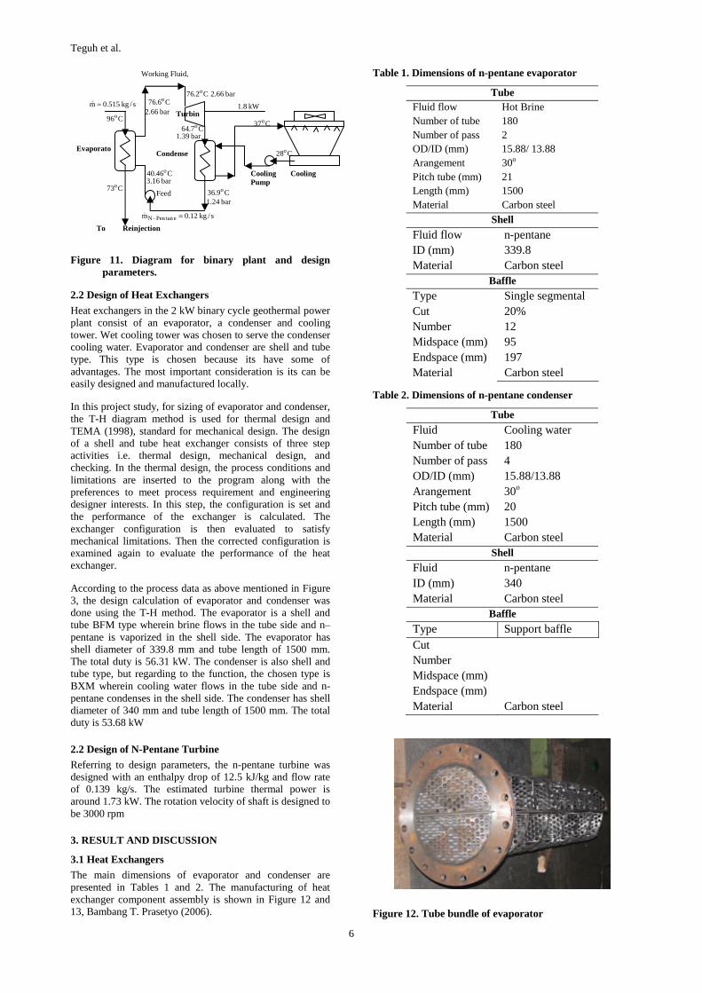
Figure 11. Diagram for binary plant and design parameters.
2.2 Design of Heat Exchangers
Heat exchangers in the 2 kW binary cycle geothermal power plant consist of an evaporator, a condenser and cooling tower. Wet cooling tower was chosen to serve the condenser cooling water. Evaporator and condenser are shell and tube type. This type is chosen because its have some of advantages. The most important consideration is its can be easily designed and manufactured locally.
In this project study, for sizing of evaporator and condenser, the T-H diagram method is used for thermal design and TEMA (1998), standard for mechanical design. The design of a shell and tube heat exchanger consists of three step activities i.e. thermal design, mechanical design, and checking. In the thermal design, the process conditions and limitations are inserted to the program along with the preferences to meet process requirement and engineering designer interests. In this step, the configuration is set and the performance of the exchanger is calculated. The exchanger configuration is then evaluated to satisfy mechanical limitations. Then the corrected configuration is examined again to evaluate the performance of the heat exchanger.
According to the process data as above mentioned in Figure 3, the design calculation of evaporator and condenser was done using the T-H method. The evaporator is a shell and tube BFM type wherein brine flows in the tube side and n–pentane is vaporized in the shell side. The evaporator has shell diameter of 339.8 mm and tube length of 1500 mm. The total duty is 56.31 kW. The condenser is also shell and tube type, but regarding to the function, the chosen type is BXM wherein cooling water flows in the tube side and n-pentane condenses in the shell side. The condenser has shell diameter of 340 mm and tube length of 1500 mm. The total duty is 53.68 kW
2.2 Design of N-Pentane Turbine
Referring to design parameters, the n-pentane turbine was designed with an enthalpy drop of 12.5 kJ/kg and flow rate of 0.139 kg/s. The estimated turbine thermal power is around 1.73 kW. The rotation velocity of shaft is designed to be 3000 rpm
3. RESULT AND DISCUSSION
3.1 Heat Exchangers
The main dimensions of evaporator and condenser are presented in Tables 1 and 2. The manufacturing of heat exchanger component assembly is shown in Figure 12 and 13, Bambang T. Prasetyo (2006).
Table 1. Dimensions of n-pentane evaporator
Tube Fluid flow Hot Brine Number of tube 180 Number of pass 2 OD/ID (mm) 15.88/ 13.88 Arangement 30o Pitch tube (mm) 21 Length (mm) 1500 Material Carbon steel
Shell
Fluid flow n-pentane ID (mm) 339.8 Material Carbon steel
Baffle Type Single segmental Cut 20% Number 12 Midspace (mm) 95 Endspace (mm) 197 Material Carbon steel
Table 2. Dimensions of n-pentane condenser
Tube
Fluid Cooling water Number of tube 180 Number of pass 4 OD/ID (mm) 15.88/13.88 Arangement 30o Pitch tube (mm) 20 Length (mm) 1500 Material Carbon steel
Shell Fluid n-pentane ID (mm) 340 Material Carbon steel
Baffle
Type Support baffle Cut Number Midspace (mm) Endspace (mm) Material Carbon steel
Figure 12. Tube bundle of evaporator
EvaporatoCondense
Feed
Cooling Cooling Pump
Turbins/kg515.0m =&
C96o
C73o
To Reinjection
Working Fluid,
C6.76 o
bar66.2
C46.40 o
bar16.3
s/kg12.0m etanPenN =−&
C9.36 o
bar24.1
C2.76 o bar66.2
kW8.1
C37o
C28o
C7.64 o
bar39.1

Teguh et al.
7
Figure 13. Assembly of evaporator and condenser
3.2 n-Pentane Turbine
The result of design calculation is shown at Figure 14, and the detailed dimensions are showed in Table 3, Bambang T. Prasetyo (2006).
Figure 14. Photo of parts and assembly of 2 kW n-pentane turbine
Table 3. Dimensions of n-pentane turbine parts
Parts Dimension Nozzle number 5.0 height mm 10.0 widht mm 5.0 angle α1(o) (o) 14.5 Rotor pitch diameter mm 382.3 shaft diameter mm 33.0 Blades number 60.0 Height mm 12/16.6 width mm 10.0 angle β1 (o) 23.8 angle β2 (o) 16.8
radius of curvature R mm 13.8 Pitch mm 20
3.3 Experiments
Performance test of the 2 kW binary cycle geothermal powerplant was carried out at Wayang Windu Geothermal Power Plant facility. The heat source for running the model
came from hot brine tapped from an injection well pipeline. The assembly of all equipment on site is shown in Figure 15.
Some measurements were established at the points as shown in the Figure 16 to analyze the performance of the binary cycle plant. The results of the experiment can be summarized in Table 4.
4. CONCLUSION
Design and performance test of the 2 kW binary cycle geothermal power plant have been accomplished. Regarding the experimental result shown in Table 4, the important things that can be inferred from this study can be summarized as follows:
• Binary cycle power plant can be applied using relatively low enthalpy heat sources.
• The methods for designing the equipments have been proven to be accurate.
Figure 15. Assembly of 2 kW binary cycle plant at Wayang Windu
Figure 16. Measurement location of parameters

Teguh et al.
8
Table 4. One of experimental series of measurements
Location Unit Design Measurement
Inlet Evap.– Brine Temp. ºC 95 110 Outlet Evap. – Brine Temp.
ºC 78.5 84
Inlet Evap. – n-Pentane Flowrate
l/min.
13.7 14
Inlet Evap. – n-Pentane Pressure
bara 3.5 3.8
Inlet Evap. – n-Pentane Temperature
ºC 40.46 38
Outlet Evap.– n-Pentane Pressure
bara 3.48 3.8
Outlet Evap. – n-Pentane Temperature
ºC 74 84
Inlet Cond. – n-Pentane Pressure
bara 1.36 1.6
Inlet Cond – n-Pentane Temperature
ºC 62.3 69
Outlet Cond. – n-Pentane Pressure
bara 1.35 1.4
Outlet Cond. – n-Pentane Temperature
ºC 41.96 48
Inlet Cond. – Cooling Water Temperature
ºC 31 32
Outlet Cond. – Cooling Water Temperature
ºC 37.5 44
Turbine – Rotation Velocity
rpm 3000 3124
Generator – Voltage V 220 210 Generator – Power W 1800 1200
REFERENCES
Bambang T. Prasetyo et all, Design and Manufacture of 2kW Binary Cycle Plant Model, Technical Report, P3TPSE-BPPT, Jakarta, 2006
Bambang T. Prasetyo et all, Design and Manufacture of 2kW N-pentane Turbine, Technical Report, P3TPSE-BPPT, Jakarta, 2006
Bambang T. Prasetyo et all, Heat Exchangers Design for BPPT 100 kW Binary Plant, Technical Report, BPPT, Jakarta, 2008
H. J. Brackenbury, D. J. Evans and D. B. Gibons, HTFS-Design Report, Harwell-National Engineering Laboratory-Chalk River Lboratories, UK, 1993
P. Shlyakhin, Steam Turbines-Theory and Design, Peace Publishers, Moscow, s.a.
R. K. Sinott, Coulson & Richardson’s Chemical Engineering, Vol. 6, Revised 2nd edition, Butterworth-Heinemann, 1998
Thomas C. Elliot, Kao Chen and Robert C. Swanekamp, Standard Handbook of Powerplant Engineering, 2nd edition, Mc Graw-Hill, 1989
TEMA, 7th Edition, 1998