Embed Size (px)
Citation preview
An autonomous, underactuated exoskeleton for load-carrying augmentation
Conor James Walsh Kenneth Pasch, ScD, PE Hugh Herr
MIT Media Lab Biomechatronics Group
Massachusetts Institute of Technology Cambridge, MA 02139, USA
Email: [email protected]
MIT Media Lab Biomechatronics Group
Massachusetts Institute of Technology Cambridge, MA 02139, USA
Email: [email protected]
1MIT Media Lab, Biomechatronics Group 2Harvard/MIT Division of Health Sciences
and Technology, Massachusetts Institute of Technology
Cambridge, MA 02139, USA Email: [email protected]
Abstract - Metabolic studies have shown that there is a
metabolic cost associated with carrying load [1]. In previous work, a lightweight, underactuated exoskeleton has been described that runs in parallel to the human and supports the weight of a payload [2]. A state-machine control strategy is written based on joint angle and ground-exoskeleton force sensing to control the joint actuation at this exoskeleton hip and knee. The joint components of the exoskeleton in the sagittal plane consist of a force-controllable actuator at the hip, a variable-damper mechanism at the knee and a passive spring at the ankle. The control is motivated by examining human walking data. Positive, non-conservative power is added at the hip during the walking cycle to help propel the mass of the human and payload forward. At the knee, the damper mechanism is turned on at heel strike as the exoskeleton leg is loaded and turned off during terminal stance to allow knee flexion. The passive spring at the ankle engages in controlled dorsiflexion to store energy that is later released to assist in powered plantarflexion. Preliminary studies show that the state machines for the hip and knee work robustly and that the onset of walking can be detected in less than one gait cycle. Further, it is found that an efficient, underactuated leg exoskeleton can effectively transmit payload forces to the ground during the walking cycle. Index Terms - exoskeleton, state-machine, control, walking
I. INTRODUCTION
A leg exoskeleton could benefit people who engage in load carrying by increasing load capacity, lessening the likelihood of injury, improving efficiency and reducing the perceived level of difficulty. Exoskeletons have been developed that amplify the strength of the wearer, apply assistive torques to the wearer’s joints and support a payload for the wearer [3][4][5]. Several exoskeleton design approaches have employed hydraulic actuators to power hip, knee and ankle joints in the sagittal plane [4][5]. Such an exoskeleton design demands a great deal of power, requiring a heavy power supply to achieve system autonomy. For example, the exoskeleton in [5] consumes approximately 2.27kW of hydraulic power, 220 Watts of electrical power, and has a total system weight of 100 lbs. This approach leads to a noisy device that has a very low payload to system weight ratio. Further, this type of exoskeleton is heavy, and if failure were to occur, could significantly harm the wearer.
Evidence from biology [6] and passive walkers [7]
suggests that legged locomotion can be very energy efficient. The exchange between potential and kinetic energy suggests that walking may be approximated as a passive mechanical process. Passive walkers reinforce this fact. In such a device, a human-like pair of legs settles into a natural gait pattern generated by the interaction of gravity and inertia. Although a purely passive walker requires a modest incline to power its movements, researchers have enabled robots to walk on level ground by adding just a small amount of energy solely at the hip or the ankle joint [8]. Recent evidence suggests that elastic energy storage is also critical for efficient bipedal ambulation. Palmer [9] showed that by characterizing the human ankle during the stance phase of walking in terms of simple mechanical spring elements, sagittal plane dynamics of a normal ankle can be reproduced at least at slow to moderate walking speeds. Further, in [10] it was shown in numerical simulation that an exoskeleton using passive elastic devices can substantially reduce muscle force and metabolic energy in walking.
Backpack
Ankle Spring
Knee Damper
Hip Actuator Pelvic Harness
Thigh Cuff
Foot Attachment
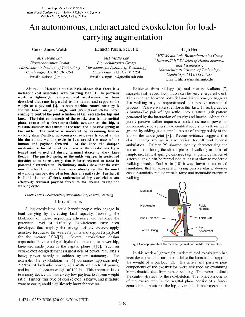
Fig.1 Concept sketch of the main components of the MIT exoskeleton. In this work a lightweight, underactuated exoskeleton has
been developed that runs in parallel to the human and supports the weight of a payload [2]. The active and passive joint components of the exoskeleton were designed by examining biomechanical data from human walking. This paper outlines the control strategy for the exoskeleton. The joint components of the exoskeleton in the sagittal plane consist of a force-controllable actuator at the hip, a variable-damper mechanism
1-4244-0259-X/06/$20.00 ©2006 IEEE
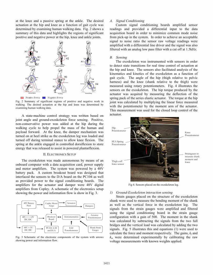
at the knee and a passive spring at the ankle. The desired actuation at the hip and knee as a function of gait cycle was determined by examining human walking data. Fig. 2 shows a summary of this data and highlights the regions of significant positive and negative power at the hip, knee and ankle joints.
Fig. 2 Summary of significant regions of positive and negative work in walking. The desired actuation at the hip and knee was determined by examining human walking data.
A state-machine control strategy was written based on
joint angle and ground-exoskeleton force sensing. Positive, non-conservative power was added at the hip during the walking cycle to help propel the mass of the human and payload forward. At the knee, the damper mechanism was turned on at heel strike as the exoskeleton leg was loaded and turned off during terminal stance to allow knee flexion. The spring at the ankle engaged in controlled dorsiflexion to store energy that was released to assist in powered plantarflexion.
II. ELECTRONICS SETUP
The exoskeleton was made autonomous by means of an onboard computer with a data acquisition card, power supply and motor amplifiers. The system was powered by a 48V battery pack. A custom breakout board was designed that interfaced the sensors to the D/A board on the PC104 as well as provided power to the signal conditioning boards. The amplifiers for the actuator and damper were 48V digital amplifiers from Copley. A schematic of the electronics setup showing the power and information flow is show in Fig. 3. Copley Motor
Amps Actuators
Joint Potentiometers
Shank Strain Gauges
PC104 A/D and D/A
48V > 5V DC/DC
Instrumentation
Dampers
Breakout Board
48V Battery Pack
48V > + - 12V DC/DC
Actuator Potentiometers
Fig. 3 Schematic of the electronic components of the system with arrows showing power and information flow.
A. Signal Conditioning Custom signal conditioning boards amplified sensor
readings and provided a differential input to the data acquisition board in order to minimize common mode noise from pick-up in the system. In order to achieve an acceptable signal to noise ratio the sensor raw voltage readings were amplified with a differential line driver and the signal was also filtered with an analog low pass filter with a cut off at 1.5kHz. B. Sensing
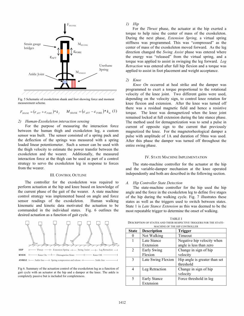
The exoskeleton was instrumented with sensors in order to detect state transitions for real time control of actuation at the hip and knee. The sensors also facilitated analysis of the kinematics and kinetics of the exoskeleton as a function of gait cycle. The angle of the hip (thigh relative to pelvic harness) and the knee (shank relative to the thigh) were measured using rotary potentiometers. Fig. 4 illustrates the sensors on the exoskeleton. The hip torque produced by the actuator was acquired by measuring the deflection of the spring pack of the series elastic actuator. The torque at the hip joint was calculated by multiplying the linear force measured with the potentiometer by the moment arm of the actuator. This measurement was used for the closed loop control of the actuator.
Knee Potentiometer
Hip Potentiometer
SEA Spring Potentiometer
Straingaues to measure shank moment and force Thigh cuff
force sensor
Fig 4. Sensors placed on the exoskeleton leg. 1) Ground-Exoskeleton interaction sensing Strain gauges placed on the structure of the exoskeleton shank were used to measure the bending moment of the shank as well as the vertical force in the exoskeleton leg. The signals from the strain gauges were amplified and filtered using the signal conditioning board in the strain gauge configuration with a gain of 500. The moment in the shank was calculated by subtracting the signals from the two full bridges and the vertical load was calculated by adding the two signals. Fig. 5 illustrates this and equations (1) were used to calculate the force and moment respectively. The gains, kf and km were determined experimentally by calibrating the raw voltage measurements with known weights applied.
MSHANK
Urethane Spring
Ankle Joint
εAFT εFORE
Strain gauge bridges
FSHANK
MANKLE
Fig. 5 Schematic of exoskeleton shank and foot showing force and moment measurement scheme.
( ) fFOREAFTSHANK kF *εε += ( ) mFOREAFTSHANK kM *εε −= (1)
2) Human-Exoskeleton interaction sensing For the purpose of measuring the interaction force between the human thigh and exoskeleton leg, a custom sensor was built. The sensor consisted of a spring pack and the deflection of the springs was measured with a spring loaded linear potentiometer. Such a sensor can be used with the thigh velocity to estimate the power transfer between the exoskeleton and the wearer. Additionally, the measured interaction force at the thigh can be used as part of a control strategy to servo the exoskeleton leg in response to forces from the wearer.
III. CONTROL OUTLINE
The controller for the exoskeleton was required to perform actuation at the hip and knee based on knowledge of the current phase of the gait of the wearer. A state machine control strategy was implemented based on angle and force sensor readings of the exoskeleton. Human walking kinematic and kinetic data motivated the actuation to be commanded in the individual states. Fig. 6 outlines the desired actuation as a function of gait cycle.
Thrust Extension Spring Swing Assist Leg Retraction
Knee On Demagnetize Knee Knee Off
Ankle free Spring compression and release Ankle free
HIP
KNEE
ANKLE
Fig 6. Summary of the actuation control of the exoskeleton leg as a function of gait cycle with an actuator at the hip and a damper at the knee. The ankle is completely passive but is included for completeness.
1) Hip For the Thrust phase, the actuator at the hip exerted a
torque to help raise the center of mass of the exoskeleton. During the next phase, Extension Spring, a virtual spring stiffness was programmed. This was “compressed” as the center of mass of the exoskeleton moved forward. As the leg direction changed the Swing Assist phase was entered where the energy was “released” from the virtual spring, and a torque was applied to assist in swinging the leg forward. Leg Retraction was entered after full hip flexion and a torque was applied to assist in foot placement and weight acceptance. 2) Knee Knee On occurred at heal strike and the damper was programmed to exert a torque proportional to the rotational velocity of the knee joint. Two different gains were used, depending on the velocity sign, to control knee rotation for knee flexion and extension. After the knee was turned off there was a residual magnetic field and hence a resistive torque. The knee was demagnetized when the knee joint remained locked at full extension during the late stance phase. The method used for demagnetization was to send a pulse in current of opposite sign to the current that previously magnetized the knee. For the magnetorheological damper a pulse with amplitude of 1A and duration of 50ms was used. After this phase the damper was turned off throughout the entire swing phase.
IV. STATE MACHINE IMPLEMENTATION
The state-machine controller for the actuator at the hip and the variable-damper mechanism at the knee operated independently and both are described in the following section. A. Hip Controller State Detection The state-machine controller for the hip used the hip angle and the force in the exoskeleton leg to define five stages of the hip during the walking cycle. Fig. 7 illustrates these states as well as the triggers used to switch between states. State 1 is Late Stance Extension as this was deemed to be the most repeatable trigger to determine the onset of walking.
TABLE I
DESCRIPTION OF STATES AND THEIR RESPECTIVE TRIGGERS FOR THE STATE-MACHINE OF THE HIP CONTROLLER
State Description Trigger 0 Not Walking Timeout 1 Late Stance
Extension Negative hip velocity when angle is less than zero
2 Early Swing Flexion
Change in sign of hip velocity
3 Late Swing Flexion Hip angle is greater than set threshold
4 Leg Retraction Change in sign of hip velocity
5 Early Stance Extension
Force threshold in leg
Min Hip Angle
Not Walking
Leg Retraction
Early Stance Extension
Late Stance Extension
Early Swing Flexion
Late Swing Flexion
Angle Threshold
Max Hip Angle
Leg Loaded
Angle Threshold
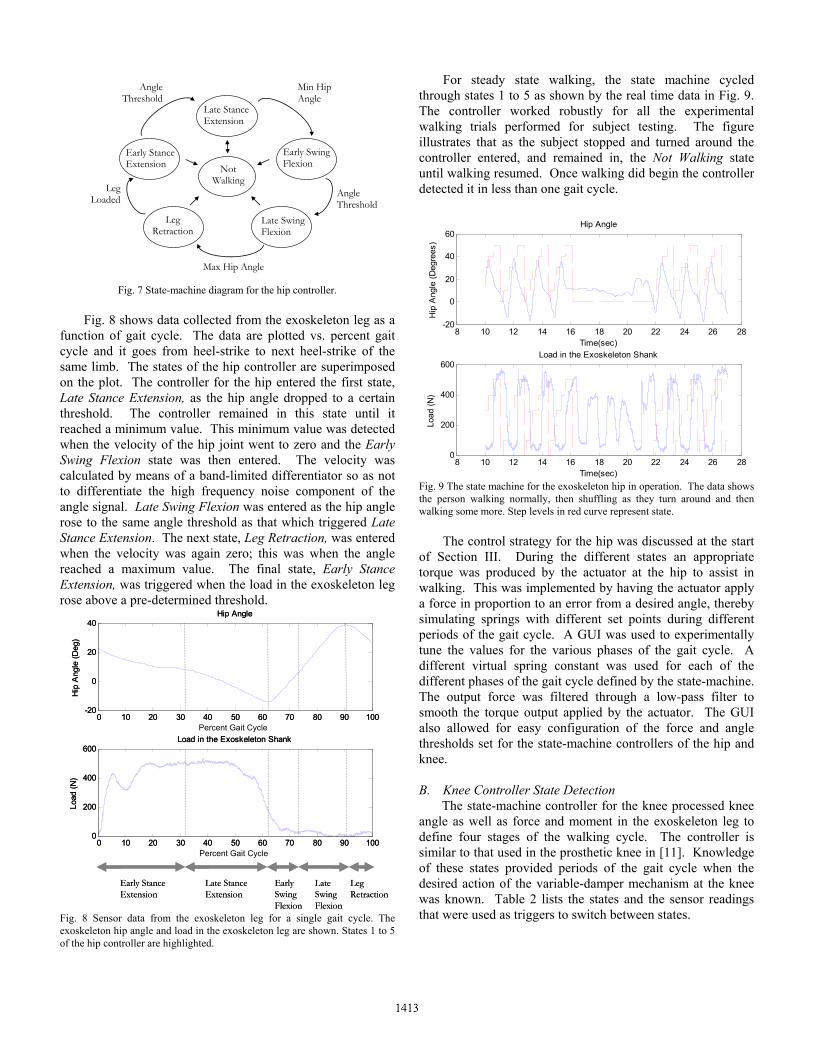
Fig. 7 State-machine diagram for the hip controller.
Fig. 8 shows data collected from the exoskeleton leg as a function of gait cycle. The data are plotted vs. percent gait cycle and it goes from heel-strike to next heel-strike of the same limb. The states of the hip controller are superimposed on the plot. The controller for the hip entered the first state, Late Stance Extension, as the hip angle dropped to a certain threshold. The controller remained in this state until it reached a minimum value. This minimum value was detected when the velocity of the hip joint went to zero and the Early Swing Flexion state was then entered. The velocity was calculated by means of a band-limited differentiator so as not to differentiate the high frequency noise component of the angle signal. Late Swing Flexion was entered as the hip angle rose to the same angle threshold as that which triggered Late Stance Extension. The next state, Leg Retraction, was entered when the velocity was again zero; this was when the angle reached a maximum value. The final state, Early Stance Extension, was triggered when the load in the exoskeleton leg rose above a pre-determined threshold.
0 10 20 30 40 50 60 70 80 90 100-20
0
20
40
Hip
Ang
le (D
eg)
Time(sec)
Hip Angle
0 10 20 30 40 50 60 70 80 90 1000
200
400
600
Load
(N)
Time(sec)
Load in the Exoskeleton Shank
Early Stance Extension
Late Stance Extension
Early Swing Flexion
Late Swing Flexion
Leg Retraction
0 10 20 30 40 50 60 70 80 90 100-20
0
20
40
Hip
Ang
le (D
eg)
Time(sec)
Hip Angle
0 10 20 30 40 50 60 70 80 90 1000
200
400
600
Load
(N)
Time(sec)
Load in the Exoskeleton Shank
Early Stance Extension
Late Stance Extension
Early Swing Flexion
Late Swing Flexion
Leg Retraction
Percent Gait Cycle
Percent Gait Cycle
Fig. 8 Sensor data from the exoskeleton leg for a single gait cycle. The exoskeleton hip angle and load in the exoskeleton leg are shown. States 1 to 5 of the hip controller are highlighted.
For steady state walking, the state machine cycled through states 1 to 5 as shown by the real time data in Fig. 9. The controller worked robustly for all the experimental walking trials performed for subject testing. The figure illustrates that as the subject stopped and turned around the controller entered, and remained in, the Not Walking state until walking resumed. Once walking did begin the controller detected it in less than one gait cycle.
8 10 12 14 16 18 20 22 24 26 28-20
0
20
40
60
Hip
Ang
le (D
egre
es)
Time(sec)
Hip Angle
8 10 12 14 16 18 20 22 24 26 280
200
400
600
Load
(N)
Time(sec)
Load in the Exoskeleton Shank
Fig. 9 The state machine for the exoskeleton hip in operation. The data shows the person walking normally, then shuffling as they turn around and then walking some more. Step levels in red curve represent state. The control strategy for the hip was discussed at the start of Section III. During the different states an appropriate torque was produced by the actuator at the hip to assist in walking. This was implemented by having the actuator apply a force in proportion to an error from a desired angle, thereby simulating springs with different set points during different periods of the gait cycle. A GUI was used to experimentally tune the values for the various phases of the gait cycle. A different virtual spring constant was used for each of the different phases of the gait cycle defined by the state-machine. The output force was filtered through a low-pass filter to smooth the torque output applied by the actuator. The GUI also allowed for easy configuration of the force and angle thresholds set for the state-machine controllers of the hip and knee. B. Knee Controller State Detection
The state-machine controller for the knee processed knee angle as well as force and moment in the exoskeleton leg to define four stages of the walking cycle. The controller is similar to that used in the prosthetic knee in [11]. Knowledge of these states provided periods of the gait cycle when the desired action of the variable-damper mechanism at the knee was known. Table 2 lists the states and the sensor readings that were used as triggers to switch between states.
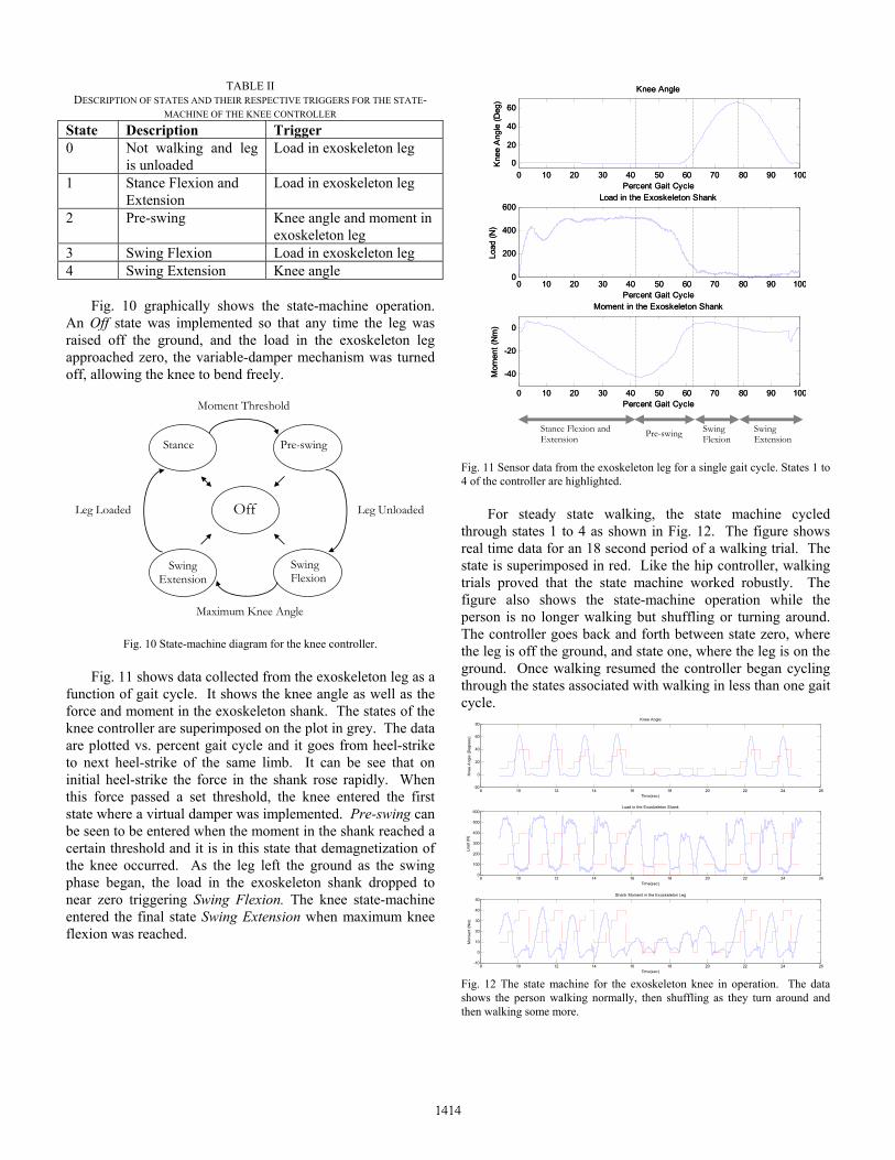
TABLE II DESCRIPTION OF STATES AND THEIR RESPECTIVE TRIGGERS FOR THE STATE-
MACHINE OF THE KNEE CONTROLLER State Description Trigger 0 Not walking and leg
is unloaded Load in exoskeleton leg
1 Stance Flexion and Extension
Load in exoskeleton leg
2 Pre-swing Knee angle and moment in exoskeleton leg
3 Swing Flexion Load in exoskeleton leg 4 Swing Extension Knee angle
Fig. 10 graphically shows the state-machine operation. An Off state was implemented so that any time the leg was raised off the ground, and the load in the exoskeleton leg approached zero, the variable-damper mechanism was turned off, allowing the knee to bend freely.
Off
Swing Extension
Pre-swing Stance
Swing Flexion
Leg Unloaded
Moment Threshold
Maximum Knee Angle
Leg Loaded
Fig. 10 State-machine diagram for the knee controller.
Fig. 11 shows data collected from the exoskeleton leg as a function of gait cycle. It shows the knee angle as well as the force and moment in the exoskeleton shank. The states of the knee controller are superimposed on the plot in grey. The data are plotted vs. percent gait cycle and it goes from heel-strike to next heel-strike of the same limb. It can be see that on initial heel-strike the force in the shank rose rapidly. When this force passed a set threshold, the knee entered the first state where a virtual damper was implemented. Pre-swing can be seen to be entered when the moment in the shank reached a certain threshold and it is in this state that demagnetization of the knee occurred. As the leg left the ground as the swing phase began, the load in the exoskeleton shank dropped to near zero triggering Swing Flexion. The knee state-machine entered the final state Swing Extension when maximum knee flexion was reached.
0 10 20 30 40 50 60 70 80 90 1000
20
40
60
Kne
e A
ngle
(Deg
)
Percent Gait Cycle
Knee Angle
0 10 20 30 40 50 60 70 80 90 1000
200
400
600
Load
(N)
Percent Gait Cycle
Load in the Exoskeleton Shank
0 10 20 30 40 50 60 70 80 90 100
-40
-20
0
Mom
ent (
Nm
)
Percent Gait Cycle
Moment in the Exoskeleton Shank
Stance Flexion and Extension Pre-swing Swing
FlexionSwing Extension
0 10 20 30 40 50 60 70 80 90 1000
20
40
60
Kne
e A
ngle
(Deg
)
Percent Gait Cycle
Knee Angle
0 10 20 30 40 50 60 70 80 90 1000
200
400
600
Load
(N)
Percent Gait Cycle
Load in the Exoskeleton Shank
0 10 20 30 40 50 60 70 80 90 100
-40
-20
0
Mom
ent (
Nm
)
Percent Gait Cycle
Moment in the Exoskeleton Shank
Fig. 11 Sensor data from the exoskeleton leg for a single gait cycle. States 1 to 4 of the controller are highlighted. For steady state walking, the state machine cycled through states 1 to 4 as shown in Fig. 12. The figure shows real time data for an 18 second period of a walking trial. The state is superimposed in red. Like the hip controller, walking trials proved that the state machine worked robustly. The figure also shows the state-machine operation while the person is no longer walking but shuffling or turning around. The controller goes back and forth between state zero, where the leg is off the ground, and state one, where the leg is on the ground. Once walking resumed the controller began cycling through the states associated with walking in less than one gait cycle.
8 10 12 14 16 18 20 22 24 26-20
0
20
40
60
80
Kne
e A
ngle
(Deg
rees
)
Time(sec)
Knee Angle
8 10 12 14 16 18 20 22 24 260
100
200
300
400
500
600
Load
(N)
Time(sec)
Load in the Exoskeleton Shank
8 10 12 14 16 18 20 22 24 26-10
0
10
20
30
40
50
Mom
ent (
Nm
)
Time(sec)
Shank Moment in the Exoskeleton Leg
Fig. 12 The state machine for the exoskeleton knee in operation. The data shows the person walking normally, then shuffling as they turn around and then walking some more.
V. PRELIMINARY RESULTS AND DISCUSSION
Initial walking experiments have been conducted with the autonomous exoskeleton loaded with a 75lb payload on an indoor athletic track at MIT. A. Kinematics The trajectory of the exoskeleton hip joint for a typical gait cycle is shown in Fig. 8. The range of motion agrees well with biological data. However, the figure shows that the trajectory of the exoskeleton hip was not as close to a sinusoid as the normal human walking hip trajectory seen in [2]. This is likely due to the increased mass attached to the human leg which limited maximum hip flexion. Fig. 11 shows the exoskeleton knee trajectory. It was similar to that of normal human knee flexion in the swing phase. However during the stance phase the knee of the exoskeleton exhibited a reduced amount of initial knee flexion and extension. This was likely due to the fact that the exoskeleton knee exerted high damping on heel strike in order to support the payload. Incorporating a spring into the design of the knee as discussed in [2], may lead to a more biological trajectory of the exoskeleton knee.
0 10 20 30 40 50 60 70 80 90 1000
100
200
300
400
500
600
Load
(N)
Percent Gait Cycle
75 lb payload
75 lb payload + 45 lb exoskeleton
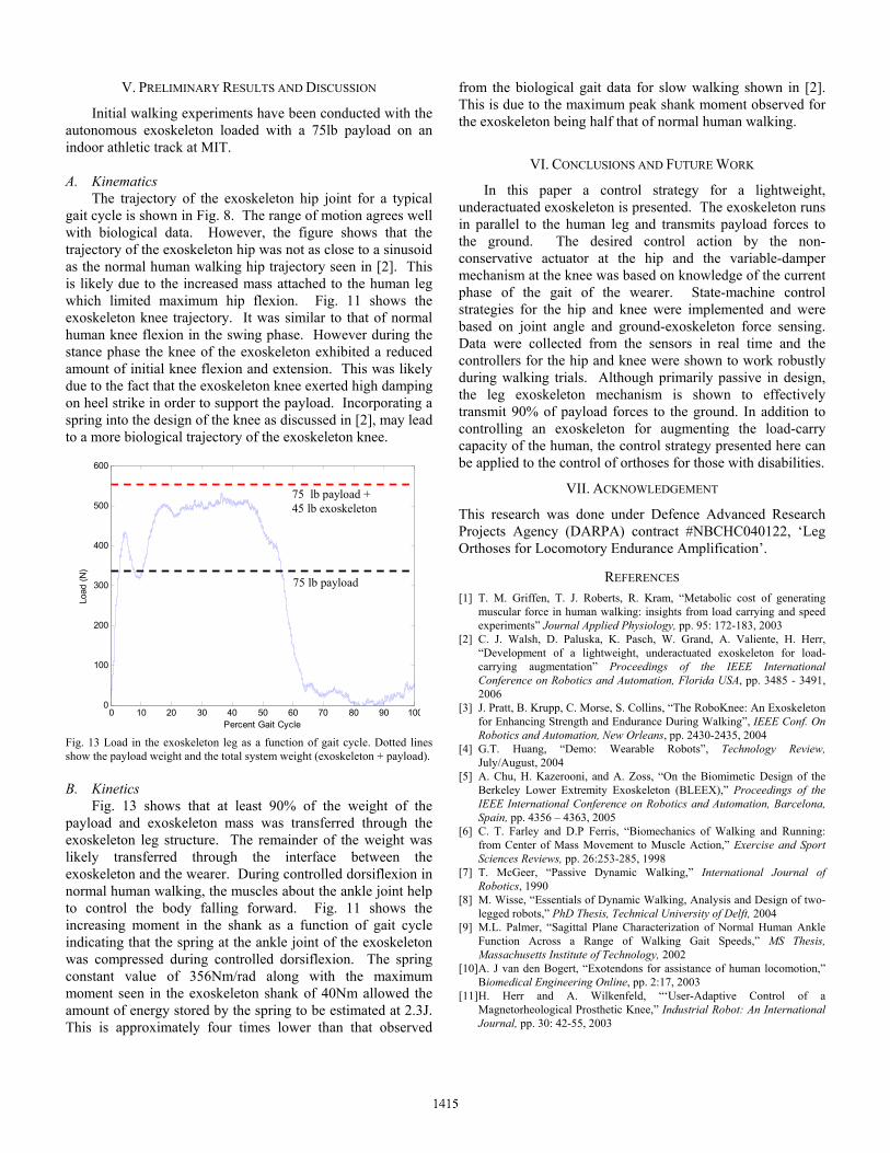
Fig. 13 Load in the exoskeleton leg as a function of gait cycle. Dotted lines show the payload weight and the total system weight (exoskeleton + payload). B. Kinetics Fig. 13 shows that at least 90% of the weight of the payload and exoskeleton mass was transferred through the exoskeleton leg structure. The remainder of the weight was likely transferred through the interface between the exoskeleton and the wearer. During controlled dorsiflexion in normal human walking, the muscles about the ankle joint help to control the body falling forward. Fig. 11 shows the increasing moment in the shank as a function of gait cycle indicating that the spring at the ankle joint of the exoskeleton was compressed during controlled dorsiflexion. The spring constant value of 356Nm/rad along with the maximum moment seen in the exoskeleton shank of 40Nm allowed the amount of energy stored by the spring to be estimated at 2.3J. This is approximately four times lower than that observed
from the biological gait data for slow walking shown in [2]. This is due to the maximum peak shank moment observed for the exoskeleton being half that of normal human walking.
VI. CONCLUSIONS AND FUTURE WORK
In this paper a control strategy for a lightweight, underactuated exoskeleton is presented. The exoskeleton runs in parallel to the human leg and transmits payload forces to the ground. The desired control action by the non-conservative actuator at the hip and the variable-damper mechanism at the knee was based on knowledge of the current phase of the gait of the wearer. State-machine control strategies for the hip and knee were implemented and were based on joint angle and ground-exoskeleton force sensing. Data were collected from the sensors in real time and the controllers for the hip and knee were shown to work robustly during walking trials. Although primarily passive in design, the leg exoskeleton mechanism is shown to effectively transmit 90% of payload forces to the ground. In addition to controlling an exoskeleton for augmenting the load-carry capacity of the human, the control strategy presented here can be applied to the control of orthoses for those with disabilities.
VII. ACKNOWLEDGEMENT
This research was done under Defence Advanced Research Projects Agency (DARPA) contract #NBCHC040122, ‘Leg Orthoses for Locomotory Endurance Amplification’.
REFERENCES [1] T. M. Griffen, T. J. Roberts, R. Kram, “Metabolic cost of generating
muscular force in human walking: insights from load carrying and speed experiments” Journal Applied Physiology, pp. 95: 172-183, 2003
[2] C. J. Walsh, D. Paluska, K. Pasch, W. Grand, A. Valiente, H. Herr, “Development of a lightweight, underactuated exoskeleton for load-carrying augmentation” Proceedings of the IEEE International Conference on Robotics and Automation, Florida USA, pp. 3485 - 3491, 2006
[3] J. Pratt, B. Krupp, C. Morse, S. Collins, “The RoboKnee: An Exoskeleton for Enhancing Strength and Endurance During Walking”, IEEE Conf. On Robotics and Automation, New Orleans, pp. 2430-2435, 2004
[4] G.T. Huang, “Demo: Wearable Robots”, Technology Review, July/August, 2004
[5] A. Chu, H. Kazerooni, and A. Zoss, “On the Biomimetic Design of the Berkeley Lower Extremity Exoskeleton (BLEEX),” Proceedings of the IEEE International Conference on Robotics and Automation, Barcelona, Spain, pp. 4356 – 4363, 2005
[6] C. T. Farley and D.P Ferris, “Biomechanics of Walking and Running: from Center of Mass Movement to Muscle Action,” Exercise and Sport Sciences Reviews, pp. 26:253-285, 1998
[7] T. McGeer, “Passive Dynamic Walking,” International Journal of Robotics, 1990
[8] M. Wisse, “Essentials of Dynamic Walking, Analysis and Design of two-legged robots,” PhD Thesis, Technical University of Delft, 2004
[9] M.L. Palmer, “Sagittal Plane Characterization of Normal Human Ankle Function Across a Range of Walking Gait Speeds,” MS Thesis, Massachusetts Institute of Technology, 2002
[10] A. J van den Bogert, “Exotendons for assistance of human locomotion,” Biomedical Engineering Online, pp. 2:17, 2003
[11] H. Herr and A. Wilkenfeld, “‘User-Adaptive Control of a Magnetorheological Prosthetic Knee,” Industrial Robot: An International Journal, pp. 30: 42-55, 2003