Embed Size (px)
Citation preview

UNIVERSITI TEKNIKAL MALAYSIA MELAKA
DESIGN AND DEVELOPMENT OF PNEUMATIC GRIPPER
FOR COMAU ROBOT
This report submitted in accordance with the requirements of the Universiti Teknikal
Malaysia Melaka (UTeM) for the Bachelor Degree of Manufacturing Engineering
(Robotic and Automation) with Honours.
By
MOHD NAZILI BIN YAACOB
FACULTY OF MANUFACTURING ENGINEERING
2009

Alamat Tetap:
Kampung Telosan
16800 Pasir Puteh
Kelantan Darul Naim
Tarikh: _________________________
** Jika Laporan PSM ini SULIT atau TERHAD, sila lampirkan surat daripada pihak berkuasa/organisasi berkenaan dengan menyatakan sekali sebab dan tempoh laporan PSM ini perlu dikelaskan sebagai
SULIT atau TERHAD.
UNIVERSITI TEKNIKAL MALAYSIA MELAKA
BORANG PENGESAHAN STATUS LAPORAN PROJEK SARJANA MUDA
TAJUK: Design and Development of Pneumatic Gripper for COMAU Robot
SESI PENGAJIAN: 2008/09 Semester 2
Saya MOHD NAZILI BIN YAACOB
mengaku membenarkan Laporan PSM ini disimpan di Perpustakaan Universiti Teknikal Malaysia Melaka (UTeM) dengan syarat-syarat kegunaan seperti berikut:
1. Laporan PSM adalah hak milik Universiti Teknikal Malaysia Melaka dan penulis. 2. Perpustakaan Universiti Teknikal Malaysia Melaka dibenarkan membuat salinan
untuk tujuan pengajian sahaja dengan izin penulis. 3. Perpustakaan dibenarkan membuat salinan laporan PSM ini sebagai bahan
pertukaran antara institusi pengajian tinggi.
4. **Sila tandakan (√)
SULIT
TERHAD
TIDAK TERHAD
(Mengandungi maklumat yang berdarjah keselamatan atau kepentingan Malaysia yang termaktub di dalam
AKTA RAHSIA RASMI 1972)
(Mengandungi maklumat TERHAD yang telah ditentukan
oleh organisasi/badan di mana penyelidikan dijalankan)
Disahkan oleh:
Cop Rasmi: Tarikh: _______________________

DECLARATION
I, hereby, declared this report entitled “Design and Development of Pneumatic
Gripper for COMAU Robot” is the result of my own research except as cited
references.
Signature : ……………………………………………..
Author’s Name : MOHD NAZILI BIN YAACOB
Date : 25 May 2009
APPROVAL
This report is submitted to the Faculty of Manufacturing Engineering of UTeM as
partial fulfillments for the degree of Bachelor of Manufacturing Engineering
(Robotic and Automation) with Honours. The member of supervisory committee is
as follow:
………………………………………………..
(Pn. Syamimi binti Shamsuddin)
Main Supervisor
Faculty of Manufacturing Engineering

i
ABSTRACT
Gripper is an important component for an industrial robot because the application of
the robot is verified according to the type of gripper utilized as its end effector. The
aim of the project is to design and develop a new and improved pneumatic gripper
for pick and place applications to be integrated with the COMAU robot available in
the Robotics Laboratory at Faculty of Manufacturing Engineering (FKP). This
project is focused in producing a pneumatic gripper that can grasp object of various
sizes and shapes effectively. Knowledge in computer aided design (CAD) and fluid
power are vital in order to complete this project. In this project, 4 types of gripper
design were suggested and the best design was selected to be fabricated. Solidworks
2005 software had been used for detail design and documentation of the gripper. The
new improved gripper is parallel type which utilizes a double acting cylinder as a
driver for the jaw movement only has one movable jaw. The other jaw is fixed and
acts as a supporter for the object to be gripped. To analyze its functionality and
effective, the gripper had been tested to grasp several shapes of object such as
spherical shape, block shape, and cylindrical shape. Results confirmed that the
improved gripper is able to grasp bigger object with various shapes compare to the
current gripper available with COMAU robot.

ii
ABSTRAK
Pencengkam merupakan komponen penting dalam sesebuah robot industri. Tujuan
utama projek ini adalah untuk mencipta dan membangunkan satu pencengkam
pneumatik baru yang telah dibaikpulih untuk aplikasi angkat dan letak bagi
diintegrasikan dengan robot COMAU yang terdapat di makmal robotik, fakulti
kejuruteraan pembuatan (FKP). Projek ini difokuskan kepada penghasilan
pencengkam pneumatik yang boleh memegang pelbagai saiz dan bentuk objek
secara cekap. Pengetahuan di dalam pereka berbantu komputer (CAD) dan kuasa
bendalir amat penting dalam melaksanakan projek ini. Dalam membangunkan
pencengkam yang baru, empat rekaan pencengkam telah dicadangkan dan rekaan
yang terbaik dipilih untuk di bina. Perisian SolidWorks 2005 digunakan untuk
proses memperincikan rekaan dan dokumentasi. Pencengkam yang baru ini
merupakan pencengkam jenis selari yang menggunakan silinder pneumatik dua arah
sebagai penggiat kepada pergerakan rahang pencengkam. Pencengkam ini hanya
mempunyai satu rahang yang bergerak and satu lagi rahang merupakan rahang tetap
yang bertindak sebagai penyokong untuk objek. Untuk menganalisis fungsi dan
keberkesanan pencengkam ini, beberapa ujian telah dijalankan dengan menggunakan
beberapa jenis objek yang berlainan bentuk. Daripada keputusan yang diperolehi
menunjukkan pencengkam baru yang telah dibaikpulih ini dapat memegang objek
yang lebih besar dan berbagai bentuk berbanding dengan pencengkam yang sedia
ada.

iii
DEDICATION
For my parents, Yaacob bin Che Noh and Halimah binti Daud, for all my siblings
and friends, and for my beloved supervisor.

iv
ACKNOWLEDGEMENT
I would like to give my gratitude toward Allah S.W.T because of His merciful and
graceful, I manage to finish up my project entitle Design and Development of
Pneumatic Gripper for COMAU Robot. I would like to thanks my beloved
supervisor, Pn. Syamimi binti Shamsuddin for all her guidance and advices along
the development of this project until finish. Without her guidance and advice, I
would have been lost. Not forgotten my co-supervisor, En. Arfauz bin A. Rahman,
thanks for supporting me while my real supervisor was not around. I truly appreciate
his effort in ensure I’m not stray from the objective of my project. I also would like
to thanks all the technicians that involve during the development of this project in
helping and give good advices on the usage of the laboratory equipment. Their
guidance is important for me in achieving my goals. To all my beloved friends and
family, thanks for supporting and helping me when I’m in need. Thank you so
much.

v
TABLE OF CONTENT
Abstract i
Abstak ii
Dedication iii
Acknowledgement iv
Table of Content v
List of Tables ix
List of Figures x
1. INTRODUCTION 1
1.1 Background 1
1.2 Problem Statement 2
1.3 Project Aim and Objective 2
1.4 Project Scope 3
1.5 Benefit of Project 3
1.6 Project Planning 4
2. LITERATURE REVIEW 6
2.1 Definition of Robot 6
2.2 Industrial Robot 7
2.2.1 Industrial Robot Anatomy 8
2.2.2 Types of Industrial Robot 10
2.2.2.1 Cartesian Robot 10
2.2.2.2 Cylindrical Robot 11
2.2.2.3 Spherical Robot 11
2.2.2.4 Articulated Robot 12
2.2.3 Robot Kinematics 12
2.2.4 Robot Programming 14
2.2.4.1 Robot Programming Method 15
2.2.4.2 Robot Programming Languages 18
2.2.5 Robot Manufacturer 20

vi
2.3 End Effector 21
2.4 Tools 23
2.4.1 Definition of Tools 23
2.4.2 Types of Tools 23
2.5 Grippers 28
2.5.1 Definition and Conceptual Basics 29
2.5.2 Gripper Flexibility 32
2.5.3 Gripper Classification. 33
2.5.4 Gripper Selection 35
2.5.5 Gripper Types 41
2.5.5.1 Impactive Gripper 41
2.5.5.2 Ingressive Gripper 44
2.5.5.3 Astrictive Prehension 45
2.5.5.4 Contigutive Prehension. 46
2.5.6 Gripper Mechanism 47
2.5.6.1 Linkages Actuation 47
2.5.6.2 Rack-pinion Actuation 47
2.5.6.3 Cam Actuation 48
2.5.6.4 Screw actuation 48
2.6 Design Tools / Software 49
2.6.1 AutoCAD 50
2.6.2 CATIA 50
2.6.3 SolidWorks 50
2.7 Pneumatic Gripper in FKP’s Robotic Laboratory 52
2.7.1 Gripper Characteristics 53
2.7.2 Gripper Mechanism 54
2.8 Previous Studies on Gripper Design for Industrial Robot 54
2.9 Summary 56
3. METHODOLOGY 57
3.1 Project Understanding and Planning 57
3.2 Research and Literature 59
3.2.1 Internet 59
3.2.2 Books, Journals, and Articles 59

vii
3.3 Study the Current Gripper 59
3.4 Define Problems and Suggest Improvement 60
3.5 Conceptual Design of a New Gripper 60
3.5.1 Procedures to used Solidwork 2005 for 3D Modeling 63
3.6 Process Planning and Tools Selection 65
3.7 Material Selection 65
3.8 Fabrication and Assembly 65
3.9 Testing and Analysis 66
3.10 Result and Troubleshooting 66
4. DESIGN AND DEVELOPMENT 67
4.1 Design Stage 67
4.1.1 First Design 68
4.1.2 Second Design 69
4.1.3 Third Design 70
4.1.4 Forth Design 71
4.1.5 Choosing the Best Design 72
4.1.6 Detail Design and Documentation 72
4.2 Development Stage 74
4.2.1 Device Selection 75
4.2.2 Material Selection for Mechanical Parts 76
4.2.3 Cutting Material into Desired Parts 76
4.2.4 Dimension Marking 78
4.2.5 Produce Shaft (Turning Process) 79
4.2.6 Milling Process 80
4.2.7 Drilling and Tapping Process 82
4.2.8 Gripper Assembly 84
4.2.9 Cost Breakdown of the Improved Gripper 87
4.2.10 Integration of the New Gripper with COMAU Robot 88
4.2.10.1 Procedure on Programming Using Teach Pendant 90
4.2.10.2 New Gripper Operation 93
5. TESTING, RESULT AND DISCUSSION 95
5.1 Gripper’s Function Test 95
viii
5.1.1 Result and Observation 95
5.2 Gripping Test 97
5.2.1 Block Shape Test 97
5.2.2 Cylindrical Shape Test 98
5.2.3 Spherical Shape Test 99
5.2.4 Result and Observation 100
5.3 Discussion 104
6. CONCLUSION AND SUGGESTIONS FOR FUTURE WORKS 107
REFERENCES 109
APPENDICES
A. Detail Drawing and Documentation
B. Programming

ix
LIST OF TABLES
1.1 Gantt chart for PSM 1 4
1.2 Gantt chart for PSM 2 4
1.3 Detail plan for fabrication works and report writing in PSM 2 5
2.1 Classification of gripper comprising 4 gripper categories 34
2.2 Selection consideration of gripper 36
2.3 The specification of the current pneumatic gripper 52
4.1 Pugh method for choosing the best design. 72
4.2 Description of gripper parts 74
4.4 Information of the pneumatic cylinder 75
4.3 List of materials 76
4.4 Cost breakdown of the improved gripper 87

x
LIST OF FIGURES
2.1 The base, arm, wrist, and end-effector forming the
mechanical structure of a manipulator 9
2.2 Cartesian robot 11
2.3 Cylindrical robot 11
2.4 Spherical robot 12
2.5 Articulated robot 12
2.6 General kinematic configuration of a robot system 14
2.7 Process of on-line programming 15
2.8 Lead-through programming process 16
2.9 Walk-through programming method 16
2.10 Of-line programming method 17
2.11 Classification of programming methods for industrial robot 18
2.12 Typical examples of end effector 23
2.13a Spot welders 25
2.13b Arc welder 25
2.14a Grinder 26
2.14b Deburrer 26
2.15 Spray gun 27
2.16 Drill as end effector 28
2.17 Possibilities for prehension of a spherical object 30
2.18 Subsystem of a mechanical gripper 31
2.19 Functional model of a gripper 32
2.20 Technical solution on achieving gripper flexibility 33
2.21 Gripper Classification 35
2.22 Consideration parameters 37
2.23 Flowchart guide to aid gripper selection 39
2.24a Pneumatic cylinder 42
2.24b Membrane drive 42
2.24c Electromechanical drive with a rotating screw nut and
guiding (skew preventing) rod 42

xi
2.24d Electromagnetic drive, opened by spring force 42
2.25 Basic design strategies for electric motors driven grippers 43
2.26 Concept of electromagnetic drive gripper 44
2.27 CluPicker mechanism gripper 45
2.28 Possibilities for vacuum production 46
2.29 Adhesive tape gripper 46
2.30 Linkages actuation 47
2.31 Rack-pinion actuation 48
2.32 Cam actuation 48
2.33 Screw actuation 49
2.34 Current pneumatic gripper attached to COMAU robot 52
2.35 Cross sectional diagram of the gripper with dimensions 53
2.36 Two three-axis gripper with force sensors 55
2.37 Reconfigurable robotic gripper 56
3.1 Project’s Flow Chart 58
3.2 Design stage 61
3.3 Solidworks 2005 software 62
3.4 Solidwork 2005 main window 63
3.5 New Solidwork document window 63
3.6 Main window for start sketching 64
3.7 Sketch and 3D features 64
4.1 Isometric view of the first design 68
4.2 Isometric view of the second design 69
4.3 Isometric view of the third design 70
4.4 Isometric view of the forth design 71
4.5 Exploded view of the new gripper design 73
4.6 Main process under fabrication 74
4.7 Laser cutting machine 77
4.8 Parts undergoes laser cutting process 77
4.9 Cutting aluminum block using band saw 78
4.10 Marking process 78
4.11 Parts undergoes turning process using lathe machine 79

xii
4.12 Turning process 80
4.13 Vertical milling machine 80
4.14 End milling process 81
4.15 Setting the work piece to be perpendicular with cutting tool 81
4.16 The final outcomes of milling process 82
4.17 Center Drill 82
4.18 Drilling process 83
4.19 Tapping process 83
4.20 Gripper assembly 84
4.21 Holes on the side of gripper’s movable jaw 85
4.22 Assembly of pneumatic cylinder with gripper’s body 85
4.23 Alignment of the guided shaft 86
4.24 Fix jaw assembly 86
4.25 New gripper mounted on the wrist end of the COMAU robot 88
4.26 COMAU robot teach pendant features 89
4.27 DOUT command to control the gripper 89
4.28 5/2 ways directional control valve 90
4.29 Create new program 91
4.30 Enter program name 91
4.31 Insert empty line for new command 91
4.32 Insert command 92
4.33 Press START to execute command 92
4.34 Program for testing the functionality of the new gripper 93
4.35 Pneumatic system 93
4.36 Operation flow 94
5.1 Function test. 96
5.2 Gripper’s jaw stuck with guided shaft. 96
5.3 Dimension of aluminum block. 97
5.4 Designed layout for pick and place operation (for the first shape). 98
5.5 Dimension of the mildsteel pipe 98
5.6 Designed layout for pick and place operation (for the 2nd shape). 99
5.7 Dimension of the golf ball. 99
5.8 Designed layout for pick and place operation (for the 3rd shape). 100

xiii
5.9 Gripping the block shape object 100
5.10 Gripping the cylindrical shape object. 101
5.11 New gripper’s jaw design. 102
5.12 Gripper’s jaw design without V-shape grove. 102
5.13 Gripping the spherical shape object 103
5.14 Comparison between gripping a golf ball and tennis ball 104
5.15 The fitting of the pneumatic cylinder 104
5.16 The movable jaw slant while gripping the ball. 105
5.17 Additional device. 105

1
CHAPTER 1
INTRODUCTION
1.1 Background
Pneumatic system is commonly used in industries such as in the robotic arm
application without having to worry about polluting the environment because the
systems only use air. It can be said that the pneumatic system is environmental
friendly. A pneumatic gripper is a specific type of pneumatic actuator that typically
involves either parallel or angular motion of surfaces that will grip an object and is
commonly used as part of a "pick and place" system that will allow a component to
be picked up and placed somewhere else as part of a manufacturing system.
Some grippers act directly on the object they are gripping based on the force of the
air pressure supplied to the gripper, while others will use a mechanism such as
sensors to control the amount of force applied to the object being gripped. Grippers
can also varied in terms of the opening size, the amount of force that can be applied,
and the shape of the gripping surfaces frequently called "Jaws". They can be used to
pick up everything from very small items to very large items. Grippers are
frequently added to industrial robots as end effectors in order to allow the robot to
interact with other objects.
This project is aimed to design and develops a working pneumatic gripper to be
integrated with the COMAU robot in Robotics Laboratory at Faculty of
Manufacturing Engineering (FKP) at Universiti Teknikal Malaysia Melaka (UTeM).
The design shall incorporate proper valves and cylinder system for pick and place
application for the robot. In order to achieve the goal of the project, CAD design and
pneumatic circuitry knowledge is crucial. Other knowledge that is required in

2
finishing this project includes machine design, applied mechanic, programming,
fabricating and material selection.
1.2 Problem Statement
The current pneumatic gripper for COMAU in FKP’s robotic laboratory is small in
size and can only grip small and light weight material. The base of the gripper
attached with the end of the robot arm is only about 55 mm x 55 mm in dimension.
The dimension of the gripper body is 50 mm x 42 mm and the thickness is 27 mm.
The jaw of the gripper it self is small. The thickness is only 1/3 from the thickness of
the body. The jaws can open maximum 10 mm both side and only can grip up to 30
mm of the material. It is also not suitable for gripping a heavy cylindrical object
because the probability the object will slip is high. The hard surface of the jaw can
easily damage the soft material surface and edge (the gripper did not construct with
build in force sensor to begin with) when grasping the material. Because the size is
small, the jaws cannot strongly hold a heavier object and probably will slip while
running the pick and place process. The external gripping force per finger effective
value is 42 N and the internal gripping force per finger effective value is 66 N.
1.3 Project Aim and Objective
The aim of this project is to design and develop a new pneumatic gripper for
COMAU. The aim is achieved through these objectives:
(a) To design and develop a new and improved pneumatic based robot gripper for
the COMAU robot in FKP’s Robotic Laboratory.
(b) To integrate the gripper with the COMAU robot available in Robotic
laboratory.
(c) To test and analyze the functionality of the gripper when integrated with the
COMAU robot.

3
1.4 Project Scope
This project is focused in designing and developing a new pneumatic based gripper
that can grasp a bigger size object with efficient grip and can reduce impact to the
object. The gripper will be designed using Solidwork software, the 3D software that
can design, simulate, and analyze the material properties use in producing the
gripper before being fabricate. This gripper will than be integrated with COMAU
robot in robotic laboratory for pick and place of two or more shapes of object. In
order to design and develop the gripper, a further study on the current gripper
available in robotic laboratory on how it mechanism and characteristics should be
conducted. At the end of the development process, testing will be carrying out to
analyze whether the gripper can work properly or not.
1.5 Benefit of project
By the end of this project, hopefully the following benefits can be achieved:
(a) Improving the grasping mechanism of the current gripper to be more efficient
and safe.
(b) Can grip various type of material shapes compare to the current robot gripper in
FKP’s robotic laboratory.
(c) The continuous research and sharing information from this project can give an
idea to develop various gripper types for more complex and flexible
application.

4
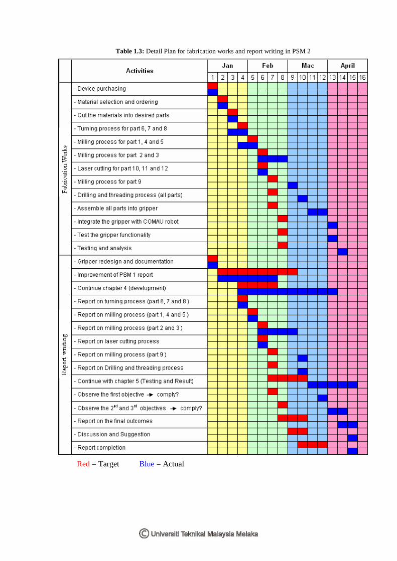
1.6 Project Planning
Table 1.1 shows the Gantt chart for activities in PSM 1 and Table 1.2 shows the
Gantt chart for activities in PSM 2. Table 1.3 shows the detail plan (weekly target)
for fabrication works (including testing and analysis) and report writing in PSM 2.
Table 1.1: Gantt chart for PSM 1
Table 1.2: Gantt chart for PSM 2
5
Table 1.3: Detail Plan for fabrication works and report writing in PSM 2
Red = Target Blue = Actual

6
CHAPTER 2
LITERATURE REVIEW
This chapter discusses about information related to this project in order to give well
understanding and good review about things that are crucially needed. This chapter
also includes the study on the existing robot gripper available with the COMAU
robot in FKP’s robotic laboratory. Beside that, the previous research from other
people that related with this project also stated.
2.1 Definition of Robot
Robot is a computer-controlled machine that can be programmed to accomplish
different task autonomously (Manseur, 2006). Different researchers divide the robot
into different categories. International Federation of Robotic, et al. (2005) divided
robot into two types which is service robot and industrial robot. According to their
definition, service robot is a robot which operated semi or autonomously to perform
services useful to the well-being of humans and equipment, excluding
manufacturing operation and industrial robot is an automatically controlled,
reprogrammable, multipurpose manipulator programmable in three or more axes,
which may be either fixed in place or mobile for use in industrial automation
applications.
Manseur (2006) grouped the robot into several types which is robot arm, mobile
robot, small-scale robot, nano-robot, parallel robot manipulator, special environment
robot, and anthropomorphic robot.

7
This research will go into detail concerning industrial robot because this project is
base on industrial robot. The next sub topic will explain in detail about the industrial
robot and its application in industries.
2.2 Industrial Robot
Groover (2008) define industrial robot as a general purpose, programmable machine
possessing certain anthropomorphic characteristic like human. Its can also be define
as a re-programmable multifunctional manipulator design to move material, parts,
tools, or specialized devices through variable programmed motions for performance
of a variety of task (McDonald, 1989 cited in Man Zhihong, 2004, p.1).
The most common anthropomorphic characteristic of industrial robot is mechanical
arm or commonly called robot manipulator, which is use to performed various
industrial tasks. Industrial robots are classified base on several characteristic.
According to Richard and Andrew (1994), the most common general characteristic
that is take consideration in classify an industrial robots are; arm configuration,
number of axes (degree of freedom), load-carrying capability, work envelope,
control system, power source, speed of movement, repeatability, accuracy, and
reliability.
Industrial robots also refer to the automatic articulated programmable transfer and
handling machine (Colestock, 2005). An industrial robot system not only includes
industrial robots but also any devices and/or sensors required for the robot to
perform its tasks as well as sequencing or monitoring communication interfaces
(Man Zhihong, 2004).
By the research from reading books and articles, the advantages of using industrial
robot in manufacturing industries can be stated as follow:
- accurate and consistent part loading
- a reduction in part defect
- increased productivity