Embed Size (px)
Citation preview

Draft
Design and Development of Autonomous Amphibious Unmanned Aerial Vehicle for in-situ Water Quality
Assessment and Water Sampling
Journal: Journal of Unmanned Vehicle Systems
Manuscript ID juvs-2020-0036.R2
Manuscript Type: Article
Date Submitted by the Author: 12-May-2021
Complete List of Authors: Manoharan, Dinesh; UCAL Fuel Systmes Limited, AerospaceC., Gajendran; UCAL Fuel Systems Limited, AerospaceM.K., Padmanabhan; Virginia Tech India Centre for Research and InnovationS., Vignesh; UCAL Fuel Systems Limited, AerospaceSankaran, Rajesh; UCAL Fuel Systems Limited, Aerospace G.D., Bhuvaneshwaran; UCAL Fuel Systems Limited, Aerospace
Keyword: Unmanned Aerial Vehicle, Hybrid UAV, Amphibious UAV, Unmanned Surface Vehicle, Hovercraft
Is the invited manuscript for consideration in a Special
Issue, Collection, or competition? :
Not applicable (regular submission)
© The Author(s) or their Institution(s)
Journal of Unmanned Vehicle Systems

Draft
1
Design and Development of Autonomous Amphibious Unmanned Aerial Vehicle
for in-situ Water Quality Assessment and Water Sampling
Dinesh Manoharana, Gajendran C.a, Padmanabhan M.K.b, Vignesh S.a, Rajesh S.a, Bhuvaneshwaran
G.D.a,
aUCAL Fuel Systems Limited, Chennai, India
bVirginia Tech India Center for Research and Innovation, Chennai, India
Corresponding author: Dinesh Manoharan
Corresponding author’s email address: [email protected]
Page 1 of 28
© The Author(s) or their Institution(s)
Journal of Unmanned Vehicle Systems

Draft
2
Abstract
This paper presents the design and development of an Autonomous Amphibious Unmanned Aerial Vehicle (AAUAV)
System with hybrid version of a Multicopter and a Hovercraft that can vertically take-off and land as well as travel on
water and smooth earth surfaces for water based applications like water quality assessment, water sampling, remote
sensing, underwater mapping etc. Based on the conceptual design, parameters such as aircraft overall dimensions, weight
estimation, aircraft performance, power requirement and endurance of the UAV were calculated and evaluated. Using
these computed parameters, a suitable propulsion system was selected. A 3D CAD model of the UAV was developed and
2D manufacturing drawings were made. Finally, a prototype of the UAV was fabricated, assembled, and all the sub-
systems were integrated. Initial trial runs were made to check the proper functioning of all sub-systems as intended.
Subsequently, to verify and validate the UAV’s concept and design configuration, ground and field tests were conducted
to test the vertical-take-off and landing, flying, and amphibious capabilities of the developed unmanned system. Results
of the tests have proven that a well-conceived Design and development has been successfully completed.
Keywords: Unmanned Aerial Vehicle, Hybrid UAV, Amphibious UAV, Unmanned Surface Vehicle, Hovercraft
1. Introduction
The commercial use of drones has increased significantly over the last few years and this trend is expected to continue in
the coming years as automation is regarded as the future in many domains. While there are many advanced aerial, surface
and underwater vehicles available commercially, cross-domain vehicle concept hasn’t been explored much. A cross-
domain vehicle concept would merge the advantages of operating in each of these domains. This paper presents a novel
concept of an Amphibious Unmanned Aerial Vehicle that can operate in air and water for in-situ water quality assessment,
water sampling and also other water-based applications like, remote sensing, underwater mapping etc. Currently,
amphibious unmanned systems i.e., unmanned vehicles capable of travelling on land and water (Shirsath et al. 2015) are
extensively used for military and rescue operations (Collins 1993). To attain the amphibious characteristics, some vehicle
designs use wheels to land, floats for water, and rotors for flying (Arhami et al. 2010). Hovercrafts are a good example of
an amphibious vehicle that uses inflatable skirts to hover and travel on land and water. Hovercraft comes in different types
Page 2 of 28
© The Author(s) or their Institution(s)
Journal of Unmanned Vehicle Systems
Draft
3
of configuration with respect to the hull type, skirt design, fan placement etc. (Knapp 2013; Okafor 2013). A Hovercraft
is an amphibian vehicle used to carry passengers and cargo on land and water surfaces (Jaiswal et al. 2014). Compared to
any other type of boats, a hovercraft does not require any surface contact for traction and can freely move on different type
of surfaces. Since there is only a marginal friction between a hovercraft and the traversing surface, they are capable of
moving forward at very less forward thrust or force depending upon surface characteristics (Tiwari 2015). The multirotor
type UAVs are a very good choice for use in amphibious vehicle because of their vertical take-off and landing capabilities
which can aid in precise and smooth landing on both land and water (Mahen M.A et al. 2014). The combination of two
vehicles, in our case a multirotor and hovercraft requires significant design and manufacturing skills to integrate (Koko
2014) as the dynamics of the vehicle are different for each vehicle with respect to their operational needs. Implementing
an efficient Vertical Take-Off and Landing (VTOL) design to an unmanned vehicle and enable them to take-off and operate
from both land and water is a significant technical challenge (Zhang 2017). This can be achieved by many technologies,
but among them, employing a multirotor system configuration is quite efficient and reliable. Multirotor systems are
primarily classified with respect to the number of rotors used and each configuration has its own advantages and
disadvantages, but as a general rule, higher the number of rotors used higher will be the flight stability (Detweiler et al.
2012). Controlling the motion and achieving precise maneuvering capabilities in a hovercraft is a very difficult task since
the speed of the hovercraft cannot be increased or reduced instantaneously due to inertia of the vehicle and less surface
friction. Similarly, maneuvering can also be difficult due to the water currents and wind gust that may be present which
can make the vehicle to drift on water (Schleigh 2006). Smooth and responsive control of the vehicle is attained by the
design of a robust controller. The development of dynamic modeling and associated controller for autonomous hovercraft
is normally achieved using Euler Lagrange method (Mohd Zamzuri et al. 2012). The Lyapunov stability criterion is used
to develop a nonlinear controller for hovercraft (Garcia and White 2015). Elementary motion detectors are used to detect
the objects in front of the vehicle and the inertial parameters are used to control the flight of a vehicle (Fuller and Murray
2011). The selection of materials is based on structure, weight, and forces acting on it. In integrating the vehicle, the
capability of the two systems working independently and in tandem is to be ensured (Yu et al. 2011). The pressure and
different loads acting on the Hovercraft hull base is important to be assessed (Abdul Kadir et al. 2011). The designed
Hovercrafts are tested initially for steady-state hovering conditions (Haider and Sajjad 2012). Based on the performance,
design modifications are done to improve the stability and reduce the drag. Although a surface vehicles and aerial vehicles
Page 3 of 28
© The Author(s) or their Institution(s)
Journal of Unmanned Vehicle Systems

Draft
4
are being used for water-based applications there are several limitations when using them such as surface vehicle can be
hard to deploy in water bodies located in remote areas and steep terrains. Similarly, multicopters have shorter endurance
and lower payload capacity compared to surface vehicles so for larger water bodies it requires multiple missions and long
durations. Moreover, the airflow from the rotors can disturb the water at sampling points thereby giving inaccurate results.
We aim to overcome these limitations by appropriate optimization and balance of the technical parameters of the
conventional unmanned systems used for water-based applications by integrating the capabilities of a surface vehicle as
well as an aerial vehicle to develop an amphibious hybrid UAV system that can provide better functionalities and broad
use cases such as remote sensing operations (Yayla et al. 2013), coastal observations (Jin and Shim 2014), helping fish
farms in seashores to monitor the fisheries (Pisanich and Morris 2002) etc.
2. Methodology
Figure 1 shows the design and development methodology of the AAUAV. Initially, a literature survey was carried out to
collect information on the existing products and technologies available in the marketplace for similar kinds of applications.
Then the conceptual design of our UAV was carried out followed by the design calculations and finally the detailed design
of the AAUAV was carried out. Proof of concept model was fabricated and the preliminary testing of the UAV was
conducted. Based on the preliminary test results, certain design modifications were made and the final design and
configuration of the AAUAV was frozen. Based on this final configuration, a prototype of the AAUAV was fabricated,
assembled and all the Sub-systems were integrated. Finally, the UAV was subjected to all functional tests including several
ground tests and field tests to check the operational capabilities of the AAUAV which include flying, landing and moving
on water surfaces etc. These tests were conducted for verification and validation of the proposed concept and design
configuration of the developed Hybrid Amphibious Unmanned Aerial Vehicle and all its sub-systems.
Figure 1 Design and development methodology of the AAUAV
Page 4 of 28
© The Author(s) or their Institution(s)
Journal of Unmanned Vehicle Systems

Draft
5
3. Literature Survey
In this section, existing products used for water sampling applications have been studied. Since there are no UAVs that is
similar to our design, three multirotor type amphibious unmanned vehicles and two surface vehicles were compared.
Fixed-wing type drones were not considered because they are much difficult to have a precise control over the landing
point and they can be operated only in water bodies that have a sufficient take-off and landing distances. The vehicles
that were studied are, “Unmanned Aerial Vehicle (UAV) - Assisted Water Sampling” by Clemson University, HexH2O
Pro V2 by QuadH2O company, BullRay Heavy Aero by Rapid composites, ESM30 USV by Ocean Alpha and Heron USV
by Clearpath Robotics. Except the BullRay, all these products deal with the extensive need of UAVs to perform water
sampling for better and accurate water quality analysis.
The “Unmanned Aerial Vehicle (UAV) - Assisted Water Sampling” by Clemson University for water quality analysis is a
hexacopter with low density foam to keep it afloat on water. It has a water collecting mechanism. However, it is incapable
of on-board analysis (Cengiz Koparan and A. Bulent Koc 2016). HexH2O is a hexacopter type amphibious drone
commercially developed by a company called QuadH2O. It is completely waterproof and is capable of heavy payload
flights. However, it is only capable of doing aerial and on water surface imagery and no real time data. The UAV system
is only used for aerial footage and then deciding which water body is visually polluted (Schroth 2017). Bullray is a rugged,
fully autonomous, waterproof and man-portable VTOL unmanned aircraft system (UAS) that can be configured for less-
than-lethal applications. It is primarily aimed to support demanding commercial, law enforcement and military needs
(Mike Ball 2017). The ESM30 is an Autonomous Water Sampling & Monitoring (USV) that can collect water samples up
to 1.8 litres and transmit real-time water quality data to the base station (OceanAlpha n.d.). Heron is a catamaran type
mapping and monitoring USV. It has a payload bay for mounting underwater sensors or equipment on deck. It can be used
for several applications such as first aid, search & rescue, surveillance, underwater mapping, water sampling and water
quality monitoring (Clearpath Robotics n.d.). The specifications of these unmanned systems are given in the Table 1.
Table 1 Existing Products Comparison
Products
Specifications Hexacopter – Clemson
University HexH2O Pro V2 BullRay ESM30 Heron
Vehicle type Multicopter Multicopter Multicopter Surface Vehicle Surface Vehicle
Page 5 of 28
© The Author(s) or their Institution(s)
Journal of Unmanned Vehicle Systems

Draft
6
Dimensions (mm x mm x mm)
550 (L) x 550 (W) x 400 (H)
650 (L) x 740 (W) x 240 (H)
1829 (L) x 1829 (W) x 635
(H)
1150 (L) x 750 (W) x 430 (H)
1350 (L) x 980 (W) x 320 (H)
Weight (kg) 2.73 4.8 45.3 31 28Payload (kg) 0.397 2 18 7.2 10Max. Speed in air (m/s) 10 15 31 NA NA
Max. Speed in water (m/s) NA NA NA 1.5 1.7
Endurance (min) 5.57 30 20 180 150
All these water-based unmanned systems were studied to understand their specifications and performance. This gives us
an idea of the design aspects for our vehicle to achieve the amphibious qualities. The problem with the multirotor type
UAVs is that they cannot travel along the water surface, have limited endurance and less payload capacity unless we use
a large multirotor drones. However, it is difficult to transport larger drones and the cost of operation also increases. On the
other hand, USVs offer a much better payload capacity and endurance but deploying them in remote areas and steep terrains
can be a very difficult task that can require a larger manpower and additional equipment. So, the main idea for combining
these two platforms was to get the best characteristics of both these vehicle types. Conventional USVs have a boat like
body that is good for travelling on water but it cannot be used as a base for landing on the ground since rocks and other
particles on the ground can damage the hull of the craft. Unlike them, Hovercrafts have a skirt around its hull that is
specifically designed for travelling on rough surfaces and are tear resistant. Power consumption can be on the higher side
in Hovercrafts but they have good performance in terms of speed and weight carrying capacity on water comparable to the
conventional boats. Hence a hovercraft was chosen as the base of our amphibious vehicle. When it comes to multicopters,
although hexa and octa rotor configurations provide much better stability compared to quadrotor the main reason for
selecting a quadrotor configuration was to keep the vehicle as compact as possible and to avoid the possible performance
loss due to the propeller stream hitting the hull of the hovercraft. Other factors such as availability of Brushless DC motors
that can produce the required thrust, propeller size payload capacity and endurance influenced the selection of the co-axial
quadcopter configuration. The aim was to develop a hybrid vehicle that as a good compromise between the multicopter
and hovercraft systems in terms of the payload, endurance, size and speed. The proposed amphibious UAV will be capable
of travelling on both air and on water surface and also on smooth land surfaces. The amphibious UAV will be modular
i.e., the multicopter and hovercraft can be disassembled and used as a separate system if needed.
Page 6 of 28
© The Author(s) or their Institution(s)
Journal of Unmanned Vehicle Systems

Draft
7
4. UAV Design
The proposed amphibious system’s design and functionality should ab initio satisfy the need of customers, relevant
industries, and various end-users. The Ideation of the AAUAV’s conceptual design was carried out, considering the
multicopter and hovercraft performance parameters including endurance, provisions for payload (such as mounting of
water sampler, hyper spectral camera, and other relevant sensors), safe landing and take-off on water as well as land,
traversing on water surface and light weight structures which are of paramount interest. In order to arrive at this, various
conceptual designs were visualized using computer-aided solid modelling and they were evaluated based on size, shape,
provision for payload, rotor configurations, space available on hovercraft’s hull, ease of integration and disassembly of
multi rotor and hovercraft modules. On studying these different configurations and also the design data from the literature
survey, an “X” type airframe with a co-axial quad motor configuration was selected for the multi copter and a plenum hull
and bag skirt configuration was chosen for the hovercraft. The “X” type co-axial motor configuration was selected since
it provides the required lift force with smaller length propeller blades thus making the drone relatively compact and also
provides good stability for our vehicle compared to “H” or “+” type airframe designs. Since the hovercraft is rectangular
in shape, when using the “H” type or “+” configuration in our vehicle, the arms of the multicopter needs to be extended a
significant amount to avoid the propeller stream from hitting the hovercraft’s hull while maintaining equal rotor distances
and symmetry of the multicopter. From our experimental testing of proof of concept models, the models with larger arms
were more agile and difficult to control manually and larger arms will also increase the overall dimensions and weight of
the vehicle. As the hovercraft hull supports the entire weight of the UAV in land and water it is important to have a rigid
structure, good stability characteristics capable of handling the high center of gravity (C.G.) and sufficient buoyancy. The
plenum hull design with a bag skirt is chosen here, it provides good rigidity as well as sufficient air volume inside the
hovercraft’s body which makes the overall density of the hull to be low and enabling the UAV to float on water. During
the rough estimation of weight and dimension of the hovercraft for the conceptual design, the volume of the hovercraft’s
hull was not sufficient enough to provide the required buoyancy to carry the initially estimated weight on its own without
inflating the skirt. Since increasing the size of the hull will significantly increase the overall weight of the vehicle which
will impact the T/W ratio of the multicopter. Hence, two floats, one on each side of the hovercraft hull was added to
provide the required buoyancy while maintaining the required T/W ratio and also provide better stability to the craft while
Page 7 of 28
© The Author(s) or their Institution(s)
Journal of Unmanned Vehicle Systems

Draft
8
maneuvering on water. Two Electric Duct Fans (EDFs) mounted to the hull will be used to inflate bag skirt and another
separate EDF in the rear of the hovercraft will be used to provide forward thrust to move the vehicle and maneuvering is
done with the help of a rudder placed behind the rear EDF. Figure 2 shows the final conceptual design of the AAUAV.
Figure 2 Conceptual design of the AAUAV
4.1. Mission Profile
The mission profile of the multicopter involves take-off from land (home point), climb to the specified mission altitude,
fly towards the first waypoint on the waterbody, land on the waterbody, take-off from the landing point after the mission
is completed, climb to the specified mission altitude, orient itself towards the home point and fly back, descend and land
at the home point.
Figure 3 Amphibious UAV mission profile
Generally, the drone will be launched from only a few meters from the waterbody of interest but we have taken a maximum
distance of 150 meters between the home point or launch point to a waterbody. At an average operating speed of 5 m/s the
drone will be able to cover 150 meters in 30 seconds. Similarly, the flying altitude was considered as 50 meters, which is
sufficiently above any trees or other obstacles that may be present in the surroundings. Considering a climb rate of 2m/s,
theoretically the drone can climb to 50 m altitude in 25 seconds. The landing phase is split into two halves, during the first
Page 8 of 28
© The Author(s) or their Institution(s)
Journal of Unmanned Vehicle Systems

Draft
9
40 meters the drone will descend at a rate of 1 m/s and for the remaining distance it will descend at a rate of 0.5 m/s to
ensure a smooth landing. So, the theoretical time taken for landing is 1 minute. The actual mission duration for the
hovercraft depends on the area of the waterbody being surveyed. However, the maximum operating duration of the
hovercraft is estimated with respect to the average or operating speed of the hovercraft which is taken as 1 m/s from the
literatures and the maximum travel distance is considered as 2 km which is sufficient enough to cover multiple sampling
points in a large waterbody. At 1 m/s the hovercraft can cover 2 km in 33 mins. After completing the mission, the hovercraft
returns to it landing point of the water body before flying back to the home point. Hence, the theoretical time take to fly to
a water body and return to the home point is about 3 minutes 50 seconds. Adding a 40 seconds buffer for the motor startup,
initial acceleration and maneuvering during various phases of the flight the total operating time for the Multicopter is
estimated as 4 minutes 30 seconds and including the hovercraft’s operation time the total minimum mission duration comes
around 37 minutes 30 seconds Apart from that the multicopter may be used to recover the vehicle in case of any emergency
conditions like hovercraft malfunction, communication loss, hovercraft battery depletion etc. by flying back to the home
point or nearby recovery site safely. These are the mission requirements for the amphibious UAV. Taking the mission
duration has the primary criteria the design of the vehicle was carried out.
4.2. Weight Estimation
Aircraft weight, as a design parameter, influences different design aspects namely structure, propulsion, aerodynamics,
center of gravity of the vehicle etc. In the preliminary design stage, weight estimation of major components of the aircraft
was derived considering the statistical data, information from the CAD model and assumptions made based on the existing
UAVs, its components, and sub-systems. Based on these data the weight of the AAUAV was calculated as shown in Table
2.
Table 2 Weight Estimation
S.No. Components Weight (Kg)1. Multicopter Airframe 2.42. Hovercraft Hull 4.53. Skirt 14. Multicopter Propulsion system 35. Multicopter Power system 5.86. Multicopter Flight control system 0.47. Payload 5
Page 9 of 28
© The Author(s) or their Institution(s)
Journal of Unmanned Vehicle Systems

Draft
10
8. Servo 0.39. Electronic Duct fan (EDF) 1.210. Electronic Speed Controller for the EDF 0.411. Hovercraft power system 512. Miscellaneous 2
Total Weight (kg) 31
4.3. MulticopterDesign
A major parameter that dictates the design of the multicopter is its estimated weight and the selection of its propulsion
system. Generally, the thrust required for a multirotor is taken as 1.8 to 2 times the Maximum Take-off Weight (MTOW)
of the UAV. Therefore, the Thrust-to-Weight ratio (T/W) was considered as 1.8. Based on the T/W the thrust required per
rotor is calculated as follows,
𝑇𝑜𝑡𝑎𝑙 𝑡ℎ𝑟𝑢𝑠𝑡 𝑟𝑒𝑞𝑢𝑖𝑟𝑒𝑑 (𝑁) = ( 𝑇𝑊) ∗ 𝑀𝑇𝑂𝑊 𝑜𝑓 𝑡ℎ𝑒 𝑈𝐴𝑉(𝑖𝑛 𝑘𝑔) ∗ 𝐴𝑐𝑐𝑒𝑙𝑒𝑟𝑎𝑡𝑖𝑜𝑛 𝑑𝑢𝑒 𝑡𝑜 𝑔𝑟𝑎𝑣𝑖𝑡𝑦
𝑇ℎ𝑟𝑢𝑠𝑡 𝑟𝑒𝑞𝑢𝑖𝑟𝑒𝑑 𝑝𝑒𝑟 𝑚𝑜𝑡𝑜𝑟 (𝑁) =𝑇𝑜𝑡𝑎𝑙 𝑡ℎ𝑟𝑢𝑠𝑡 𝑟𝑒𝑞𝑢𝑖𝑟𝑒𝑑
𝑁𝑜.𝑜𝑓 𝑀𝑜𝑡𝑜𝑟𝑠
From the above equations, the required thrust from each motor of the multicopter was determined to be 68.42 N. Based on
this, a 320 KV Brushless DC (BLDC) Motor with a 22” x 6.6” propeller combination was selected which generates a
maximum thrust of 70.41 N (T-Motor n.d.) which is above the required thrust to maintain a T/W of 1.8. The total frame
size of the multicopter was decided based clearance required between the muticopter propellers and the space required for
placement of other components on the multicopter and it was estimated to be 1.4 m x 1.4 m.
4.4. Hovercraft Design
The major requirement of the hovercraft’s design is the space that is needed to carry the payload, batteries, all the required
avionics, provision for integrating the multicopter and also the volume needed for producing the required buoyancy to
keep the 31 kg AAUV afloat on water. So, the length and width of the hovercraft was selected based on these parameters.
The design ratios and other design assumptions were made as per the General Design Rules (GDR) normally followed in
the design of hovercraft (Elsley and Devereux 1968). With reference to the GDR, the hovercraft design parameters were
computed. The calculated hovercraft design parameters are shown in Table 3
Design Assumptions,
Length to width ratio is1.5
Page 10 of 28
© The Author(s) or their Institution(s)
Journal of Unmanned Vehicle Systems

Draft
11
Bag Pressure (Pb) to Cushion Pressure (Pc) ratio (Bag Skirt Type Hovercraft) is 1.3
Hover Gap, h = 0.0127 mm
Forward Thrust (Tf) to weight (W) ratio while hovering is 0.2
Pitch (p) to Diameter (d) ratio of Propeller is 0.6≤
The size of the hovercraft was decided based on the sufficient space required for mounting the multicopter, placement of the water
sampling unit and other subsystems. With the selected length (0.75 m), width (0.5 m) and height (0.1634 m) of the hovercrafts hull, the
Volume of water displaced by the hovercraft is 0.0306 m3. Hence the buoyant force of the hovercraft is 300 N which is less than the
overall weight of the vehicle. Keeping in mind not to significantly increase the overall weight of the vehicle so as to maintain the T/W
ratio, two floats each of dimensions 0.34 m x 0.15 m x 0.10 m were added to provide the required additional buoyancy. The resultant
buoyant force after adding the floats is 400 N which is higher than the overall weight of vehicle hence it will float even without inflating
the bag skirt.
Table 3 Calculated design parameters of the hovercraft
Parameter ValueLength of Hovercraft 0.75 m
Cushion Area 0.375 m2
Cushion Pressure 810.43 N/m2
Air Exit velocity 36.37 m/sAir Escaping Area 0.03175 m2
Airflow Rate required 1.155 m3/sPower required per EDF 935.78WForward thrust required 60 N
To achieve the required cushion pressure of 810.43 N/m2, exit airflow rate of 1.55 m3/s, each one of the two EDFs for
inflated the skirt must be able to push air at a power of 935.78 W and the rear mounted EDF must be able to produce 60N
thrust. Based on these requirements a 70mm 2200 KV EDF was selected which can generate the required rate of airflow
to inflate the bag-skirt and maintain the required air pressure inside and also produce the required thrust for propelling the
vehicle forward. The rate of airflow escaping through the holes provided underneath the craft creates the air gap needed
for the hovercraft to hover smoothly on water.
Page 11 of 28
© The Author(s) or their Institution(s)
Journal of Unmanned Vehicle Systems

Draft
12
4.5. Power System Selection and Endurance Estimation
Based on the maximum voltage and power required by the propulsion system selected for the muticopter and hovercraft,
suitable Lithium Polymer (LiPo) batteries were chosen as the power source for the UAV. The nominal voltage per cell in
a LiPo battery is 3.7 V and the maximum voltage per cell is 4.2 V. The batteries were selected based on the maximum
current drawn and operating voltage of the motors, endurance required by the multicopter and the hovercraft, and also
taking into account the maximum allowable weight of the UAV.
The BLDC motor used for the multicopter has a maximum current draw of 58.6 A and an operating voltage of 22.2 V [22].
However, it will be able to provide the required thrust for operating the UAV at 70% to 80% of its max power capacity.
So, an average power draw of 33 A (at 75% throttle) per motor was considered based on the data sheet provided by the
manufacturer. Therefore, the average total current drawn by all the motors in the multicopter was estimated as 264 A. The
current drawn by subsystems including flight controller, telemetry etc. of the multicopter comes to around 4 amps. So the
total current drawn by the multicopter is 268 amps Considering the allowable weight limit of the vehicle and the operating
voltage of the multicopter motors two 6S or 6-cell (22.2V) 22000mAh LiPo batteries with a discharge rate of 25C were
selected. So, the total energy available from the multicopter battery is 44000mAh or 44Ah. The total battery capacity
divided by the total current drawn gives the endurance of multicopter which comes around 10 minutes. Similarly, the EDFs
used in the hovercraft have an average current draw of nearly 21 A per EDF at an operating voltage of 14.8 V The two
EDFs used for inflating the bag skirt will operate at nearly at a constant rpm for most of the mission while the forward
thrust producing EDF will have variable operating power draw depending on the path, environmental conditions, etc. The
current consumed by flight controller and Raspberry Pi Model B is around 0.7 A. Therefore, the average total current
drawn by the hovercraft was estimated as 64 A. Hence, two 4S or 4-cell 16000mAh 25C LiPo batteries were selected for
powering the hovercraft which amounts to a total battery capacity of 32 Ah. Hence, the estimated endurance of the
hovercraft will be around 30 minutes. Therefore, the total endurance of the UAV will be up to 40 minutes.
4.6. Flight control and communication system
Flight Control System (FCS) acts as the brain of the UAV, as all the operations of the vehicle are controlled and monitored
by the flight control unit. Generally, a FCS comprises of Main Control Board (MCB) that contains the computer program
which computes and controls the UAV’s performance. In addition, an IMU (Inertial Measurement Unit), a Geographical
Page 12 of 28
© The Author(s) or their Institution(s)
Journal of Unmanned Vehicle Systems

Draft
13
Positioning System (GPS) module, a compass and other external sensors are also mounted. These sensors provide the
MCB with the data required for its operations such as, vehicle speed, attitude, the direction of heading, location, etc. Due
to the modular nature of the vehicle, it was necessary to use two FCS Systems i.e., one for the multicopter and one for the
hovercraft operations so that it can be used separately if needed. It is also provided with pre-built compatibility for various
airframe configurations along with various advanced FCS features and capabilities such as return-to-home, geographic
fence, collision avoidance etc. The Pixhawk 2.4.8 flight control board along with the PX4 firmware is used for the control
and autonomous operation of the vehicle. Both Pixhawk and PX4 are open source platforms with the capability to be used
with different vehicles including, multirotors, fixed wings, rovers, surface vehicle, hybrid vehicle like VTOLs etc. apart
from it, we can develop our own flight control algorithms as per our vehicle needs. For our vehicle we have used the inbuilt
vehicle configuration of x type co-axial quadcopter configuration for the multicopter and the boat configuration for our
hovercraft since it uses a rudder for vectoring the thrust similar to a boat.
Figure 4 Flight control and communication system architecture
The ultimate aim is to perform all the tasks completely autonomously. Since two separate FCS were used, they needed to
operate in coordination to control the craft as per the mission and all the processes also need to be executed automatically.
This is achieved by developing an appropriate algorithm and the associated computer program that can communicate with
both the flight control systems simultaneously via mavlink protocol and provide appropriate commands without needing
a ground operator to manually control each part of the mission. The developed program was implemented in a Raspberry
Pi Model B computer board which acts as a medium or hub between the two FCS systems as illustrated in Figure 3 for
Page 13 of 28
© The Author(s) or their Institution(s)
Journal of Unmanned Vehicle Systems

Draft
14
providing seamless switchover between the two flight controllers during the course of a planned mission. The Raspberry
Pi is used for combining the two flight controllers and giving commands to them via mavlink as per the mission details set
in the Ground Control Station. However, the switching can also be done manually using the remote if needed. The user
can set the mission details in the Ground Control Station (GCS) application. As per the mission data input, the GCS will
transmit the command signals wirelessly via RF module (data telemetry) using the UART protocol to the Raspberry Pi.
Wherein the Raspberry Pi acts as a central processing unit and processes the commands of the mission and transmits it to
the pixhawk flight controllers which then controls the AAUV.
5. Proof of Concept Testing
Before fabricating a prototype, the performance of the multicopter and the hovercraft modules need to be tested to verify
the actual performance against the theoretical estimations. For this purpose, proof of concept model of the hovercraft and
multicopter were fabricated and tested as standalone systems to achieve satisfactory performance without any flaws in
their operational capabilities before integrating them as a single unit. Various static and dynamic tests were conducted to
study the hovercraft’s performance parameters such as skirt pressure, exit velocity, throttle conditions, and speed of the
Hovercraft. The exit velocity at each skirt hole was measured using a SKYWATCH Explorer handheld anemometer which
has a small fan suitable for measuring airspeed from small outlet areas. When operating the EDFs at 55% throttle an
average exit velocity of around 36.76 m/s was achieved from each of the 22 holes in the bag skirt, From the exit velocity,
the average airflow rate at each hole was calculated to be 0.051 m3/s. Hence the total airflow rate from all the holes comes
to 1.167 m3/s. This airflow rate is sufficient for generating the required cushion pressure of 810.43 N/m2.
Since the required cushion pressure was achieved at 55% throttle of the duct fans, vehicle speed tests were conducted from
50% throttle of the duct fans and progressively increased to 100% and the performance of the vehicle at different throttle
positions were computed. Further, the hovercraft’s speed on land was estimated by measuring the time taken to travel a
certain distance at the given throttle percentage. Markers were placed on the floor at 5 meter intervals, and the hovercraft
was made to accelerate from the starting point to the ending point by slowing increasing the throttle and keeping it constant
at a certain percentage. The time taken for the hovercraft to move from starting point to the end point was recorded and
the speed of the hovercraft was calculated by dividing the distance traveled by the time taken. Similarly, the speed of the
hovercraft at different throttle positions were estimated.
Page 14 of 28
© The Author(s) or their Institution(s)
Journal of Unmanned Vehicle Systems

Draft
15
Figure 5 Hovercraft testing on water
Speed Tests were also carried out in water similar to the procedure mentioned above. The results of the speed tests as
measured experimentally and the data from the flight controller is given in the Table 4 and Table 5. The results show that
the hovercraft traveled much faster in water than on land. This difference in speed could be attributed to the different
frictional forces on water and land.
Table 4 Hovercraft performance on land
S.No
Hovering Motor
Throttle(%)
Forward Motor Throttle
(%)
Current Consumed
(A)
Speed – Experimental
(m/s)
Speed – from FCS(m/s)
1. 30 49.5 1.95 2.022. 50 58.75 2.26 2.193. 70 66.75 3.14 3.224.
55
100 73 3.65 3.58
Table 5 Hovercraft performance on the water
S.No
Hovering Motor
Throttle(%)
Forward Motor Throttle
(%)
Current Consumed
(A)
Speed – Experimental
(m/s)
Speed – from FCS(m/s)
1. 30 49.3 2.81 2.732. 50 57.87 3.12 3.103. 70 67.2 3.95 3.924.
55
100 72.8 5.05 5.12
Subsequently, flight tests of the multicopter system was carried out to check its stability and performance at maximum
load-carrying conditions. Initial flight tests were conducted to study the behavior of the UAV at normal and windy
conditions and based on the UAVs performance, the proportional–integral–derivative (PID) control in the FCS was tuned
Page 15 of 28
© The Author(s) or their Institution(s)
Journal of Unmanned Vehicle Systems

Draft
16
to make the corrective response of the FCS towards any deviations in performance more precise. After fine tuning the PID,
the maximum payload carrying capacity and flight endurance of the multicopter were also checked by using dummy
payloads. The test was carried out only till 80% throttle since it is not safe to operate the motors close to the fully loaded
conditions for a long period of time.
Figure 6 Multicopter flight test
Table 6 Multirotor hover flight test results
S.NoPayload Weight
(kg)
Take-off Weight
(kg)
Hover Throttle
(%)
Flight Time(min)
Average current draw (A)
Battery Remaining
(%)
Estimated Endurance
(min)
1. 0 16 50% 5 91.7 83% 28.82. 5 21 65% 5 160.4 70% 16.53. 10 26 70% 5 200.8 62% 134. 15 31 75% 5 263.2 50% 10
Table 6 shows the current drawn and the estimated endurance of the vehicle at different payload capacities. It can be seen
that the multicopter performed as predicted in the theoretical calculation with an endurance 10 mins at maximum take-off
weight of 31 kg. Both the multicopter and the hovercraft as individual systems performed satisfactorily without any major
problems. Then they were integrated into a single hybrid system for further testing.
Page 16 of 28
© The Author(s) or their Institution(s)
Journal of Unmanned Vehicle Systems

Draft
17
Figure 7 Hybrid UAV static testing in water
Subsequently, the buoyancy and stability of hybrid vehicle was tested in water by means of visual observation as shown
in Figure 7. Flight tests were carried out to check stability and control responses of the multicopter. The flight test results
showed that the FCS produced good control responses for any changes in the UAVs attitude which is indicated by the
matching response of the PID controller to changes in moments as shown in Figure 8.
Page 17 of 28
© The Author(s) or their Institution(s)
Journal of Unmanned Vehicle Systems

Draft
18
Figure 8 PID response to pitch, roll and yaw
6. Figure AAUAV Prototype Fabrication, Integration and Testing
The multicopter and hovercraft airframe were manufactured from carbon fiber composites. Initially, the multicopter
mainframe was assembled and all the necessary wiring from the power distribution board to the inner arms were made
accordingly. The power distribution board had two sets of power supply inputs which were used to provide power supply
to all the motors and the other flight components viz., LED, flight controller, camera, etc. Separate BECs were provided
accordingly for other components with a regulated power supply. Landing gears were attached to the multicopter
mainframe arms using aluminum clamps and secured using fasteners. Motors, ESCs, and LEDs were connected to each of
the four outer arms of the multicopter and respective propellers were mounted onto the motors. The flight controller was
mounted on to the airframe, the GPS module, power module, safety buzzer connections were made accordingly. The RC
receiver was connected via S-Bus port to the flight controller using a servo wire. The servo signal wires from each ESC
Page 18 of 28
© The Author(s) or their Institution(s)
Journal of Unmanned Vehicle Systems

Draft
19
were connected to the output port of the flight controller, the batteries were connected and calibration of the UAV was
carried out using QGround Control Software. The fully integrated multicopter is shown in Figure 9.
Figure 9 Fully integrated multicopter
The Hull of the hovercraft was fabricated from carbon composite and the skirt was made from polyurethane fabric. The
hovercraft skirt was attached to the bottom and top of the hull using supporting frames and screws. A thin rubber seal was
provided between the hull and skirt attachment to prevent leaking of any air from inside the hovercraft. Electric duct fans
were attached to the respective motor mounts on top and back of the hull. The power supply, ESC, servo motor and the
flight controller connections were made as seen in Figure 10; the batteries were connected to the hovercraft and it was
calibrated.
Figure 10 Fully integrated hovercraft
Page 19 of 28
© The Author(s) or their Institution(s)
Journal of Unmanned Vehicle Systems
Draft
20
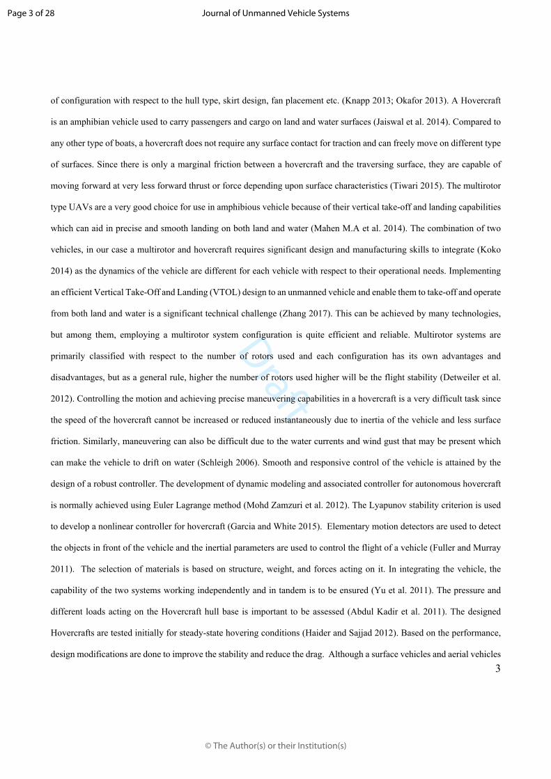
Finally, both the multicopter and hovercraft were integrated together to form a single hybrid UAV as shown in Figure 11.
The Raspberry Pi computer board was mounted on to the UAV and flight controller connections were made accordingly.
An RF module was connected to the UAV and another to the GCS for communication and data transmission.
Figure 11 Fully integrated AAUAV prototype
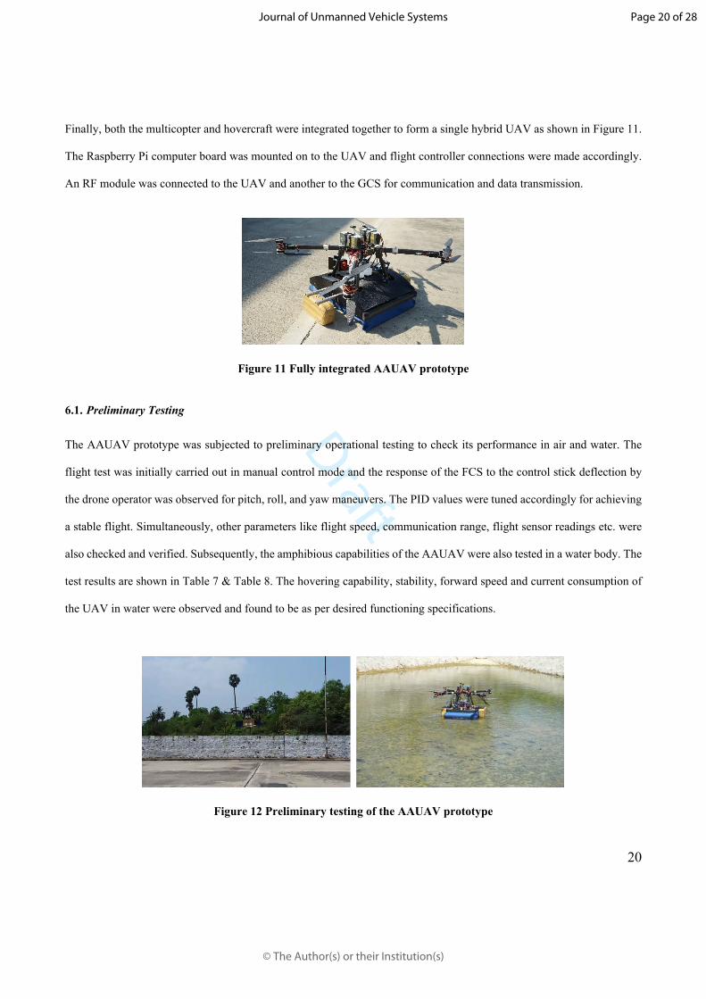
6.1. Preliminary Testing
The AAUAV prototype was subjected to preliminary operational testing to check its performance in air and water. The
flight test was initially carried out in manual control mode and the response of the FCS to the control stick deflection by
the drone operator was observed for pitch, roll, and yaw maneuvers. The PID values were tuned accordingly for achieving
a stable flight. Simultaneously, other parameters like flight speed, communication range, flight sensor readings etc. were
also checked and verified. Subsequently, the amphibious capabilities of the AAUAV were also tested in a water body. The
test results are shown in Table 7 & Table 8. The hovering capability, stability, forward speed and current consumption of
the UAV in water were observed and found to be as per desired functioning specifications.
Figure 12 Preliminary testing of the AAUAV prototype
Page 20 of 28
© The Author(s) or their Institution(s)
Journal of Unmanned Vehicle Systems

Draft
21
Table 7 Amphibious UAV – Hovercraft mode test results in water
S.No
Hovering Motor
Throttle(%)
Forward Motor Throttle
(%)
Current Consumed
(A)
Speed – Experimental
(m/s)
Speed – from FCs(m/s)
1. 30 49.50 0.78 0.702. 50 56.63 0.92 0.963. 70 67.33 1.05 1.024.
55
100 73.1 1.3 1.28
Table 8 Amphibious UAV – Multirotor mode flight test results
S.No. Parameters Value1. Take-off Weight 31 kg2. Flight time 8 mins3. Flight Speed 5 m/s4. Current drawn 264.46 A5. Voltage drawn 23.4 V6. Battery Remaining 25 %
6.2. Field Test
Field testing of the UAV was carried out to check and validate the different operational capabilities and performance of
the UAV under actual environmental conditions prevailing in the field of operation. The flight test was conducted in a
larger water body and the evaluation was done based on parameters such as speed, stability, maneuverability, endurance,
payload carrying capability. On completion of all pre-flight checks, the AAUAV was powered on and the mission details
like the home point location, waypoints, flight speed, altitude, fail-safe conditions, etc. were programmed into the GCS
and the mission was initiated. Figure 13 shows the planned mission flight path of the vehicle.
Figure 13 Mission flight path of the Amphibious UAV
Page 21 of 28
© The Author(s) or their Institution(s)
Journal of Unmanned Vehicle Systems

Draft
22
The UAV took off from the home point (launch point) and flew towards the water body. After reaching the specified
waypoint, the UAV started descending and landed on the water surface as planned. As the UAV starts descending, the two
EDFs on the hovercraft’ hull were switched ON which inflated the bag skirt to keep the AAUAV float in water as shown
in Figure 14.
Figure 14 UAV taking off and landing on the water surface
After the AAUAV lands on the water surface, the flight controller automatically detects that the vehicle has landed and it
proceeds to switch off the muticopter rotors and disarms them. After the rotors are disarmed the status of the same is sent
to the raspberry pi via mavlink protocol. Then, the pi gives a command to the Hovercraft’s FCS to arm the EDFs. The
forward thrust producing EDF pushes the AAUAV forward along the surface of the water. The rudder attached to the servo
motor was used to control the heading direction of the AAUAV as it navigated along the specified waypoints as shown in
Figure 15. After completing the planned mission on water, the AAUAV returned in hovercraft mode to the initial landing
point on the water surface.
Page 22 of 28
© The Author(s) or their Institution(s)
Journal of Unmanned Vehicle Systems
Draft
23
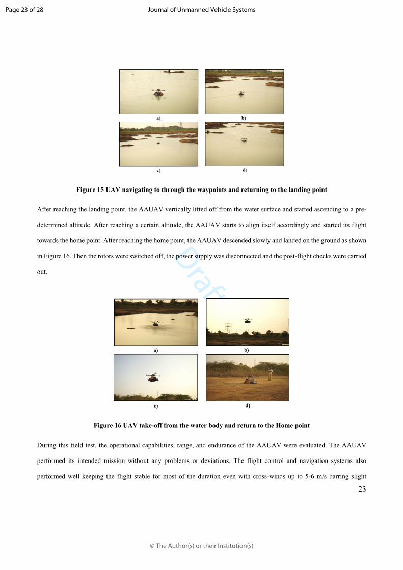
Figure 15 UAV navigating to through the waypoints and returning to the landing point
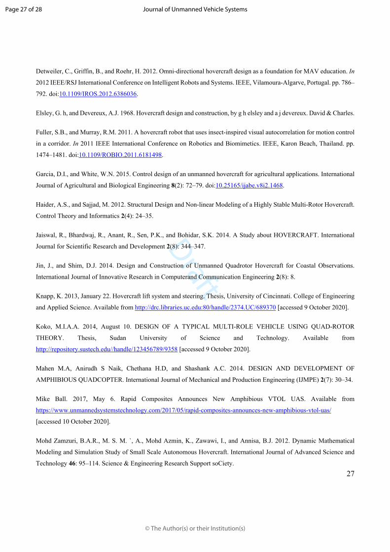
After reaching the landing point, the AAUAV vertically lifted off from the water surface and started ascending to a pre-
determined altitude. After reaching a certain altitude, the AAUAV starts to align itself accordingly and started its flight
towards the home point. After reaching the home point, the AAUAV descended slowly and landed on the ground as shown
in Figure 16. Then the rotors were switched off, the power supply was disconnected and the post-flight checks were carried
out.
Figure 16 UAV take-off from the water body and return to the Home point
During this field test, the operational capabilities, range, and endurance of the AAUAV were evaluated. The AAUAV
performed its intended mission without any problems or deviations. The flight control and navigation systems also
performed well keeping the flight stable for most of the duration even with cross-winds up to 5-6 m/s barring slight
Page 23 of 28
© The Author(s) or their Institution(s)
Journal of Unmanned Vehicle Systems

Draft
24
oscillation occasionally when cross-winds speeds were greater than 6 m/s. This is due to two reason, firstly the vertical
axis C.G is lower relative to the multicopter and the hovercraft’s larger surface area below the multicopter acts as a wall
of resistance to the sudden external force from cross-winds which creates high moments so, slight oscillations were
observed. However, it was being damped quickly by the response from the Flight controller and higher thrust rotors. These
oscillations can be avoided by find a much better compromise in C.G between the multicopter and the hovercraft. Another
solution is by reducing the overall weight of the vehicle using better materials thereby increasing thrust-to-weight ratio of
the vehicle which can provide better resistance and stability against high winds. A nominal GPS accuracy error of ±2m
was observed. As estimated in the theoretical calculations, the UAV achieved its total Endurance of 40mins with 20%
battery power remaining. The flight data from the mission is shown in Figure 17, Figure 18, Figure 19 & Figure 20.
Figure 17 Flight Path – Planned vs Actual
Figure 18 Battery Voltage vs Time
Page 24 of 28
© The Author(s) or their Institution(s)
Journal of Unmanned Vehicle Systems

Draft
25
Figure 19 Motor outputs (PWM vs Time)
Figure 20 Multicopter Pitch, Roll and Yaw Angles
7. Conclusion
In conclusion, a novel concept of a Hybrid Amphibious UAV with fully autonomous operational capabilities has been
designed and developed. The multicopter and hovercraft units fabricated, integrated, and tested individually as well as a
hybrid system functioned extremely well. Extensive laboratory and field tests were successfully carried out to assess
performance, stability, autonomous operation and navigational capability in air and on water. The final field trials were
also successful with the AAUAV satisfying all its operation, performance and endurance parameters. The modular nature
and heavy payload capacity of the UAV enable it to be used for a multitude of applications including aerial imagery,
Page 25 of 28
© The Author(s) or their Institution(s)
Journal of Unmanned Vehicle Systems

Draft
26
mapping, remote sensing, payload delivery, etc. and also for water-based applications like water quality analysis, water
sample collection, underwater mapping, rescue operation and so on. In future, we plan to use better materials and advanced
manufacturing techniques for reducing the overall weight of the vehicle to improve the total endurance and payload
capacity. Further design optimizations will also be carried out to reduce the overall height of the vehicle to move the
vertical C.G relatively closer to the body of both the multicopter as well as hovercraft for achieving better stability.
Author Statements
Acknowledgment:
This research project was carried out under Indo-Korea bilateral R&D grant-funded and supported by Global Innovation
& Technology Alliance and Department of Science & Technology, Govt. of India. We thank them for their support and
guidance.
Competing Interests:
The authors declare there are no competing interests.
References
Abdul Kadir, A., Salit, M.S., and Jaafar, A.A. 2011. Development of a hovercraft prototype with an aluminium hull base.
International Journal of Physical Sciences 6(17): 4185–4194. Academic Journals. doi:10.5897/IJPS10.31.
Arhami, Hasnan, K., and Wahab, A.Ab. 2010. Towards the conceptual design and construction of an unmanned small-
scale air-land-water vehicle. In 2010 International Conference on Computer Applications and Industrial Electronics. IEEE,
Kuala Lumpur. pp. 98–103. doi:10.1109/ICCAIE.2010.5735055.
Cengiz Koparan, and A. Bulent Koc. 2016. Unmanned Aerial Vehicle (UAV) assisted water sampling. In 2016 ASABE
International Meeting. American Society of Agricultural and Biological Engineers. doi:10.13031/aim.20162461157.
Clearpath Robotics. (n.d.). Heron Unmanned Surface Vessel for Aquatic Research. Available from
https://clearpathrobotics.com/heron-unmanned-surface-vessel/ [accessed 10 October 2020].
Collins, K.A. 1993, June. A concept of unmanned aerial vehicles in amphibious operations. Thesis, Monterey, California.
Naval Postgraduate School. Available from https://calhoun.nps.edu/handle/10945/39778 [accessed 9 October 2020].
Page 26 of 28
© The Author(s) or their Institution(s)
Journal of Unmanned Vehicle Systems
Draft
27
Detweiler, C., Griffin, B., and Roehr, H. 2012. Omni-directional hovercraft design as a foundation for MAV education. In
2012 IEEE/RSJ International Conference on Intelligent Robots and Systems. IEEE, Vilamoura-Algarve, Portugal. pp. 786–
792. doi:10.1109/IROS.2012.6386036.
Elsley, G. h, and Devereux, A.J. 1968. Hovercraft design and construction, by g h elsley and a j devereux. David & Charles.
Fuller, S.B., and Murray, R.M. 2011. A hovercraft robot that uses insect-inspired visual autocorrelation for motion control
in a corridor. In 2011 IEEE International Conference on Robotics and Biomimetics. IEEE, Karon Beach, Thailand. pp.
1474–1481. doi:10.1109/ROBIO.2011.6181498.
Garcia, D.I., and White, W.N. 2015. Control design of an unmanned hovercraft for agricultural applications. International
Journal of Agricultural and Biological Engineering 8(2): 72–79. doi:10.25165/ijabe.v8i2.1468.
Haider, A.S., and Sajjad, M. 2012. Structural Design and Non-linear Modeling of a Highly Stable Multi-Rotor Hovercraft.
Control Theory and Informatics 2(4): 24–35.
Jaiswal, R., Bhardwaj, R., Anant, R., Sen, P.K., and Bohidar, S.K. 2014. A Study about HOVERCRAFT. International
Journal for Scientific Research and Development 2(8): 344–347.
Jin, J., and Shim, D.J. 2014. Design and Construction of Unmanned Quadrotor Hovercraft for Coastal Observations.
International Journal of Innovative Research in Computerand Communication Engineering 2(8): 8.
Knapp, K. 2013, January 22. Hovercraft lift system and steering. Thesis, University of Cincinnati. College of Engineering
and Applied Science. Available from http://drc.libraries.uc.edu:80/handle/2374.UC/689370 [accessed 9 October 2020].
Koko, M.I.A.A. 2014, August 10. DESIGN OF A TYPICAL MULTI-ROLE VEHICLE USING QUAD-ROTOR
THEORY. Thesis, Sudan University of Science and Technology. Available from
http://repository.sustech.edu//handle/123456789/9358 [accessed 9 October 2020].
Mahen M.A, Anirudh S Naik, Chethana H.D, and Shashank A.C. 2014. DESIGN AND DEVELOPMENT OF
AMPHIBIOUS QUADCOPTER. International Journal of Mechanical and Production Engineering (IJMPE) 2(7): 30–34.
Mike Ball. 2017, May 6. Rapid Composites Announces New Amphibious VTOL UAS. Available from
https://www.unmannedsystemstechnology.com/2017/05/rapid-composites-announces-new-amphibious-vtol-uas/
[accessed 10 October 2020].
Mohd Zamzuri, B.A.R., M. S. M. `, A., Mohd Azmin, K., Zawawi, I., and Annisa, B.J. 2012. Dynamic Mathematical
Modeling and Simulation Study of Small Scale Autonomous Hovercraft. International Journal of Advanced Science and
Technology 46: 95–114. Science & Engineering Research Support soCiety.
Page 27 of 28
© The Author(s) or their Institution(s)
Journal of Unmanned Vehicle Systems

Draft
28
OceanAlpha. (n.d.). ESM30 | Unmanned Surface Vehicle 丨 OceanAlpha. Available from
https://www.oceanalpha.com/product-item/esm30/ [accessed 10 October 2020].
Okafor, B. 2013. Development of a Hovercraft Prototype. International Journal of Engineering and Technology 3(3).
Pisanich, G., and Morris, S. 2002. Fielding an amphibious UAV: development, results, and lessons learned. In Proceedings.
The 21st Digital Avionics Systems Conference. IEEE, Irvine, CA, USA. pp. 8C4-1-8C4-9.
doi:10.1109/DASC.2002.1052944.
Schleigh, J. 2006. Construction of a Hovercraft Model and Control of its Motion. Thesis. Available from
https://drum.lib.umd.edu/handle/1903/6603 [accessed 9 October 2020].
Schroth, F. 2017, March 13. New Waterproof Drone Hits the Market — the HexH20 Pro V2. Available from
https://dronelife.com/2017/03/13/new-waterproof-drone-hits-the-market-the-hexh20-pro-v2/ [accessed 10 October 2020].
Shirsath, P.S., Hajare, M.S., Sonawane, G.D., Kuwar, M.A., and Gunjal, M.S.U. 2015. A REVIEW ON DESIGN AND
ANALYSIS OF AMPHIBIOUS VEHICLE. International Journal of Science, Technology & Management 04(01): 16.
Tiwari, A. 2015. TO STUDY AND FABRICATION OF AIR CUSHION VEHICLE. Int. J. Res. Granthaalayah 3(3): 70–
84. doi:10.29121/granthaalayah.v3.i3.2015.3034.
T-Motor. (n.d.). MN605-S KV320 - 2PCS/SET_Navigator Type_Motors_Multirotor_T-MOTOR Store-Official Store for
T-motor drone motor, ESC, Propeller. Available from https://store-en.tmotor.com/goods.php?id=472 [accessed 10 October
2020].
Yayla, M., Sarsilmaz, S.B., Mutlu, T., Cosgun, V., Kurtulus, B., Kurtulus, D.F., and Tekinalp, O. 2013. Dynamic Stability
Flight Tests of Remote Sensing Measurement Capable Amphibious Unmanned Aerial Vehicle (A-UAV). In Proceedings
of the 7th Ankara International Aerospace Conference AIAC, Ankara, Türkiye. pp. 11–13.
Yu, S.-C., Pyo, J.-H., Cho, P.C., Kim, D.-Y., Park, M.-K., and Hwang, C.-S. 2011. Preliminary Study On Robotic
Amphibious Vehicle. International Society of Offshore and Polar Engineers. Available from
https://www.onepetro.org/conference-paper/ISOPE-I-11-323 [accessed 9 October 2020].
Zhang, S. 2017. Review of Vertical Take-Off and Landing Aircraft. In 2017 Second International Conference on
Mechanical, Control and Computer Engineering (ICMCCE). IEEE, Harbin. pp. 53–56. doi:10.1109/ICMCCE.2017.9.
Page 28 of 28
© The Author(s) or their Institution(s)
Journal of Unmanned Vehicle Systems