Embed Size (px)
Citation preview

Design and Development of a New Cargo Parachute and Container Delivery System
Bruce Bonaceto & Peter StalkerU. S. Army Soldier Systems Center-Natick, MA 01760 USA
Abstract
The U S Army Soldiers Systems Center, Product Manager Force Sustainment Systems at Natick ,MA was tasked with the development of a new low cost Container Delivery System (CDS). Theprogram plan was to develop a new airdrop container, a High Velocity parachute and a Low Velocityparachute as alternatives to existing CDS components. Current CDS is used to support missions thatprovide water, food and supplies to areas unreachable by other means or to quickly provide theseitems on the spot for military operations. In actuality, very few airdrop items are returned for reuseand only in training does reuse occur. The High Velocity parachute and a Low Velocity parachuteuse the same basic design principles to keep the costs as low as possible. The container has beensimplified in construction and is still able to perform its mission. These designs are based on using ahigh tear resistant, low cost, woven, polypropylene material. New materials and methods to producea low cost parachute were investigated during this program. This led to examining the basic premiseof parachute design and to challenge some of these basic concepts to see if the labor costs could bereduced through a simpler design and using standard, low cost, commercially available material.These concepts eliminate reinforcement of the canopy and use the inherent strength of low cost,canopy stock width material, along with a slower opening design to withstand the high parachuteopening shock. The suspension lines are tied directly to the canopy material, reducing the number ofsuspension lines and eliminating the labor associated with sewing them on. This innovative parachutedesign is new in both geometry and method of construction. This is a modified cross parachute designthat uses several strips of fabric that cross the other fabric at 90 degrees and are spaced so thatcrown vents are created to increase the geometric porosity and reduce opening shock. The number ofsuspension lines are reduced using this new design. The standard 26 ft Ringslot High ‘V’ chute has 26lines compared to the new 12 line design. The G-12 cargo parachute has 64 compared to the new 20line design. The fabric runs from one side of the parachute over the top to the other side without abreak in the fabric so as not to create weak points at junctions. c. Stitching is kept to a minimum byonly sewing the edges of the wide material at their edges where they intersect the other fabric thatcrosses at the crown and at the ends. Fabrication can be accomplished by non parachute makers suchas tent or sail makers. A low cost slider is used on the high velocity, high altitude parachute tofurther reduce opening shock. As a result, the cost is reduced by approximately 60% of the presentinventory items and at the same time decent rate is reduced by 4 % to 12 %. Testing to date has beensuccessful with the High Velocity chute and the container having completed all formal testing and areaccepted for their intended use of loads up to 2,200 pounds and altitudes up to 25,000 feet. The LowVelocity chute has shown that it can deliver 2,200 pounds with a rate of descent of 25 feet/second andis now being tested in its final configuration before entering formal testing.This paper describes thenew container and the design of the two new parachutes and discusses airdrop test results.
I. Introduction
For many years the U S Army and other world governments have used A-22 containers to delivermiscellaneous items of supplies and equipment by means of cargo airdrop. The items are delivered byeither High-Velocity or Low-Velocity parachutes and from C-130 or C-17 aircraft. Up to 40 containerswith up to 2,200 pounds each can be delivered by this method. This method of airdrop is known as theContainer Delivery System (CDS) and has proven itself to be an effective way to deliver suppliesmeasuring no more than 4 ft x 4 ft x 4ft and weighing between 501lbs and 2,200 lbs. The A-22 container isplaced on a plywood skidboard and several layers of energy-dissipating honeycomb are used under the A-22 to attenuate the ground impact shock and protect the supplies. High-Velocity airdrop has a descent rateof 70 to 90 ft/sec; for Low-Velocity the descent rate is 28.5 ft/sec or below.
18th AIAA Aerodynamic Decelerator Systems Technology Conference and Seminar AIAA 2005-1647
This material is declared a work of the U.S. Government and is not subject to copyright protection in the United States.
During Operation Provide Promise in Bosnia, United States (U.S.) Forces delivered aid usingover $31 million of standard airdrop equipment with no equipment recovered, clearly identifying a need fora low cost one-time use CDS alternative for airdrop missions of this type.
II Low Cost Airdrop System (LCADS) Requirements
The LCADS will provide an efficient low-cost aerial delivery capability for the full spectrum of Armyoperations to include combat re-supply missions, Stability and Support Operations (SASO), and MilitaryOperations Other Than War (MOOTW). The LCADS creates a low-cost means of addressing the logisticalre-supply needs found in those ambiguous situations residing between peace and war, such as peacekeepingand peace enforcement operations, as well as humanitarian relief operations and support to domesticauthorities. LCADS is comprised of three items: the Low Cost Container, Low Cost High-VelocityParachute, and Low Cost Low-Velocity Parachute. All components are simple in design, maintenance,operation, and potential refurbishment, thus generating low development and lifecycle costs andminimizing materiel lead times, and come pre-packed from the manufacturer.
The LCADS must be designed so that it cost less than current system, thus reducing mission costs.The intent of this system is to create a low-cost system that can deliver supplies at a cost that is less than55% of current systems. A maximum suspended load weight of 2200 lb load capacity will allow supplies that typically weightbetween 501 and 2,200 lbs to be delivered to intended recipients on the ground. Supplies must be deliveredto a specific point on the ground where they can be recovered and used to support the full spectrum ofmilitary operations or humanitarian relief efforts. High velocity (the ability to rapidly descend throughwinds) is required to attain delivery accuracy when delivery aircraft must fly high over the target due toterrain, weather, or ground threat. During high velocity airdrops, a descent rate of no greater than 90 feetper second is desired so that a load can be rigged to survive the force of impact. It is nearly impossible torig an airdrop load to survive an impact greater than 90 feet per second. During low-velocity airdrops, adescent of no greater than 28.5 feet per second is desired so that a load can be rigged to survive the 19Gforce of impacting the ground. .
The LCADS must be compatible with Army and Air Force air and ground support platforms andsimultaneous air-droppable from standard U.S. Air Force cargo aircraft and special operations, NATO, andother services aircraft.
LCADS must be capable of being deployed at current CDS release altitudes: for High-Velocity airdropof between 1,250 feet above ground level (AGL) to 25,000 feet mean sea level (MSL) and 500 to 1,250 feetAGL for Low Velocity airdrop.
The LCADS must have a probability of successful airdrop completion without the occurrence of asystem abort that makes the airdropped load non-mission capable after ground impact of at least 0.92.
III Low Cost A-22 Container (LCC)
The Low Cost Container is a low-cost alternative to the A-22 cargo container. The LCC isdesigned for single use air delivery and will not be recovered. It will be used to contain standard CDSoperational loads ranging in weight from 501 to 2,200 lbs. It will be airdropped at aircraft speeds of up to150-KIAS at altitudes of 501 to1,200-ft AGL and 15,000 to 25,000-ft MSL. Weight 10 lbs; dimensionsapprox 48-inx48-in base, four approx 7-ft long sidepieces (approximately the same as the A-22).
The LCC shown in Figure 1is made of 2-in polypropylene webbing stitched in a simplified versionof the A-22 cargo bag, with a standard D-ring at the apex of each of its four “crow’s foot” shaped sides anda standard friction adapter on each of the 2 restraining straps. The LCC is placed on top of the energydissipater material. The sides of the container are laced together around the load (a load of 4 water drums isshown in Figure 1). The LCC is tied to the skid and the parachute is tied to the ‘D’ rings of the LCC.
Both High-Velocity and Low-Velocity airdrops using the LCC were conducted to assess theoperational effectiveness and suitability for U. S. Army use. Rigged loads weighed from 501 to 2,200 lbs atairspeeds of 140 to 150 knots from C-130 and C-17 aircraft. Airdrops were conducted at an altitude of25,000 feet for High-Velocity airdrop and 1,200 feet for Low-Velocity airdrop. The LCC met all the designcriteria and its performance equaled that of the standard A-22 containers.

Figure. 1 LCC Rigged for High ‘V’ Airdrop
IV Design of the High-Velocity Parachute
A. Materials
Several materials were evaluated for the High Velocity parachute canopy material: nylon, non-woven polyesters, polyethylene scrim films and woven polypropylenes. The woven polypropylene wasdetermined to be the most suitable. Polypropylene is a polymer that derived from the processing of crudeoil and natural gas. A weave of 24 x 11 strips were used for the High-V design. This material is widelyused as a geo-textile to build silt fences, and in road building and repair as a stabilizer and separator. It hasthe advantage of low cost combined with high tear resistance, elasticity, tenacity and the best porosity forthis chute design. Nylon sells for $2 to $5 per square yard where as the 3.5 ounce woven polypropylene isselling from $0.20 to $0.50 per square yard. Tests showed the woven polypropylene to have a tearresistance over 3 times stronger than a similar weight of nylon material. These qualities led to a newdesign that used more material, yet allowed for simplification of the design, so that the labor to make theparachute and the overall costs were lower. It is estimated that the use of this material for parachutes whenstored will last up to 20 years.
The High V parachute uses twelve 3/8” diameter ropes that tie on to the canopy. This reducednumber of suspension lines means that stronger lines were required. Three ply twisted rope was selectedbecause of its low cost and good elastic properties.

Figure 2. High-Velocity Parachute
B. Construction
Low cost is achieved by constructing a parachute with the least amount stitching and the fewestsuspension lines resulting in reduced manufacturing time. The High-Velocity parachute uses 12 suspensionlines, rather than the 26 lines of the 26-ft ringslot parachute. This is accomplished by using the materialitself to distribute the load over the 3-foot wide leg material. A sleeve is created at both ends of each panelby folding the end over and sewing it to itself. The suspension line is threaded through the sleeve andknotted in place. The other end of the suspension line (Figure 2) is tied to the container. The only stitchingon the canopy is where the edges of each panel intersect the other panels at 90 degree angle. The totalamount of stitching on the High V canopy is 128 feet as compared to the 420 feet for the 26-ft ringslot.Stitching is performed by a 4-needle cable stitch machine.
C. Detail of Design
This design evolved from the cross parachute. Building on the cross chute’s simplicity of designand fabrication, the legs of the cross parachute were broken up into three separate panels and spaced apartto create four vent holes in the crown and vertical slots in the legs. This distance was empiricallydetermined to provide the best geometric porosity and to reduce the opening shock. The relatively hightenacity polypropylene warp fibers run from one side of the parachute to the other side. The fibers aregathered together and attached to the suspension line that is tied thru the sleeve.
The three suspension lines for each side of the chute are tied on to the corresponding rings on thecontainer to save the cost of the attaching clevis. An ‘X’ shaped load spreader is made from 1 ¼” nylonwebbing. Each three lines are routed thru each corresponding webbing end and attached with 80 lb cotton.The spreader is added to the lines 3 feet above the container to provide a wide confluence point andessentially extend the container attaching points and eliminate the extensions used on the A-22 container. Asimple ‘X’ slider is used to further reduce opening shock and to provide control of badly deployed chutes.

V Design of the Low-Velocity Parachute
Figure 3. Low ‘V’ Parachute
A. Materials
A 2.7 ounce woven polypropylene was selected for this design, which has the same properties asthe material used in the High-V parachute
A 5/16” nylon three-ply twisted rope was selected because of its low cost and good elasticproperties. The Low-V parachute design reduces the number of suspension lines from 64 to 20 lines.
B. Detail of Design
The same basic design principles are used in the Low-V parachute as the High-V parachute. Tenstrips of machine woven material at 7.33 feet wide are cut to 90 feet long. Five panels are crossed with thefive more panels and sewn at the edges on the crown. They are spaced apart and crossed at 90 degrees tocreate sixteen vents in the crown (Figure 3) to increase geometric porosity and reduce opening shock. Thisis a greater challenge than the High-V parachute because the suspension line forces must be transmittedfrom a single point to spread over the 7.33 foot wide panel material. Also packing and unfolding such widepanels is difficult and was only achieved through several trials of packing and reefing methods. Stitchingwas performed by a 4-needle cable stitch machine. The same method of attaching the lines to the canopywas as the High-V by forming sleeves at the end of the panels for the lines to be tied too.
The five suspension lines for each side of the chute are attached to snap hooks. The four snaphooks are used to quickly attach to the four corresponding ‘D’ rings of the container. An ‘O’ ring is usedaround the suspension lines 5 feet above the container to provide a single confluence point and essentiallyextend the container’s risors attaching points and eliminate the extensions used on the A-22 container.
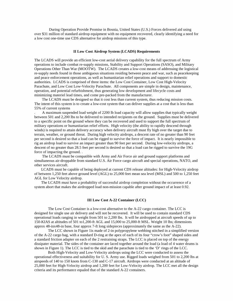
Testing showed that to achieve our goal of being .92 reliability that a hem organizer/reefingsystem was need to prevent parachute damage during a bad deployment The skirt of the parachute wasconnected together at the attachment point where the suspension lines attach to the canopy to prevent thepossibility of a skirt inversion which allows one or more legs to move outside of the skirt to inflate on theirown which causes unsymmetrical inflation and chute damage. Several reefing designs have beensuccessfully tested to date: slider, reefing line with break ties and permanent ties attaching the legstogether.
Figure 4. Low ’V’ Parachute Deployment from C-17
Figure 5. Low ‘V’ Chute Reefed Figure 6. Low ‘V’ Chute Inflatedwith a Slider
C. “Chute First” Parachute Deployment
It was decided to use “Chute First” parachute deployment instead of the present G-12 pilot chutedeployed. This accomplishes three things: saves the cost of the 68” pilot chute, eliminates the trailing staticlines from the aircraft and provides better low altitude performance. A low cost deployment bag designshown in Figure 7. attached to a A-22 load, was made from the same material as the canopy. The bag is asimple design that is open at one end and at the opposite end has a hole in which the ’O’ ring is attached tothe bag. The suspension lines are thread thru the ‘O’ ring from inside the bag. The excess lines are folded inthe bottom of the bag and the canopy is folded on top of the lines. A static line is attached to the apex of thecanopy. The bag is attached to the load with a 5 foot 9/16” tubular tied to the ‘O’ ring. Cotton break tieshold the parachute on the load. The other end of the static line is attached to the aircraft anchor cable with abreak tie. The static line during deployment shown in Figure 4.pulls the canopy out of the bag and then thestatic line detaches from the aircraft anchor cable when the break tie is broken.

Figure 7. Low ‘V’ Chute Rigged for Airdrop
VI High ‘V’ Airdrop Testing at The Yuma Proving Grounds1
A. Test Conditions
A total of 61 CDS with the Low Cost Hi-V Parachute were dropped for Phase 2, which include 25 singleCDS and 36 CDS in mass deployment formation. On C-130 aircraft, 20 instrumented-singles and one passof 16 CDS (a full stick) were dropped. On C-17 aircraft, 5 instrumented-singles and one pass of 20 CDS(half of a full stick), one CDS of which was instrumented, were dropped. Initially, 20 CDS were to bedropped from the C-17 as well as from the C-130 aircraft All drops were conducted from 25,000 ft meansea level (MSL) at airspeeds between 130 and 150 knots-indicated-airspeed (KIAS) on Mohave Drop Zoneat Yuma Proving Ground. Most of the DT CDS were rigged with the LCADS LCC due to a low supply ofstandard A-22 containers. Single drops were weighted to the maximum CDS weight of approximately2200 lbs. Mass deployment drops contained CDS with weights ranging from 500 to 2200 lbs.Instrumented CDS were equipped with strain links and PDAS for gathering opening force data and utilizedoptical tracking ground cameras to record time-space-position information for obtaining the velocity atimpact. Mass deployment drops were observed to note any air starvation caused by neighboring canopies.Low-Cost Hi-V data were compared post-drop with data gathered for the 26-Ft RS canopy during Phase 1
B. Kineto Tracking Mounts (KTMs)
The dynamic performance for all of the LCADS loads was measured using optical trackers called KTMs.Dynamic performance includes altitude losses, descent rates, and trajectory reconstruction. Each KTM hasa precision-tooled stabilized tracking mount with azimuth and elevation encoders which are sampled alongwith Coordinated Universal Time (UTC) once every video or camera frame. These data were coded ontothe edge of each video frame. The KTM mounts each have four independent camera stations which cansupport a mix of 70-mm, 35-mm, and video cameras. At a minimum, three KTMs are used to record thedrops in order to generate Time, Space Position Information (TSPI) data. The video tapes are read after thedrops. The video reading station is equipped with a decoder and video reading software. The decoderallows the edge data (time, azimuth and elevation) to be read with each video frame. Calibration targets areused to determine the scale of video pixels to radians, which are known as “Reader Constants.” TheReader Constants give the conversion needed to calculate the azimuth and elevation of any pixel on thevideo screen, which is referenced to the center of the payload. Each test object is read to an individual filewhich contains time, azimuth, elevation, x counts (pixels), and y counts. Once these data files are created,they are processed to provide the TSPI solution. The processing is conducted using YPG-developedsoftware which first reads-in each data file and uses the computed Reader Constants to produce the angularmeasurement to the test object. The software takes each measurement at a corresponding time to compute
TSPI by calculating the nearest intersection of each angular measurement. A sliding filter smoothes theoutput of TSPI and the program allows for rotation and translation of the output, if required.
C. Strain Links
Strain links were used to measure opening shock on the LCADS loads. The strain links consist of a metal“dog-bone,” full-bridged strain patch and amplifier. The output from the strain links was recorded on thePortable Data Acquisition System (PDAS) recorder. PDAS is a ruggedized, self-containedmicrocontroller-based data logger which provides up to eight channels of 12-bit resolution 0-5 volts, directcurrent (vDc) analog input, as well as a logic level switch input for event flagging. It has 2 Mb of non-volatile memory, which allows for up to 4 minutes of recording four channels at 1000 Hz sample rate.After recording, ASCII text data or binary data can be downloaded to a personal computer (PC) via an RS-232 connection. The amplified strain link output is 0-5 vDc, which is what PDAS digitizes and records.The voltage data are converted to force (pounds) by using a “K-factor” determined by the YPG CalibrationLaboratory, and are unique to each link. To compute opening shock, the channel at each time interval isplotted, from which the maximum strain link force is determined. This maximum force experienced isdivided by the suspended weight of the load. This gives opening shock in “G’s” (acceleration due to theearth’s gravity: 32.2 ft/s2 or 9.81 m/s2).
D. Video
Ground-to-Air video was recorded using a stabilized KTM mount. A high-speed lens, 250 frames persecond, was also used on the mount as a means of slow-motion tracking of the opening sequence of everyLCADS drop. Onboard video cameras were placed to capture three main views: First Motion, Ramp, andOverall. The First Motion camera shows the initial movement of the CDS bundle and any interaction thebundle might experience on the inside of the aircraft. The Ramp camera points out the ramp door anddown, to give a view of the initial canopy opening sequence. The overall camera was mounted furthertowards the cockpit but points towards the ramp, giving an overall view of each CDS bundle exiting theaircraft.
E. Descent Rate
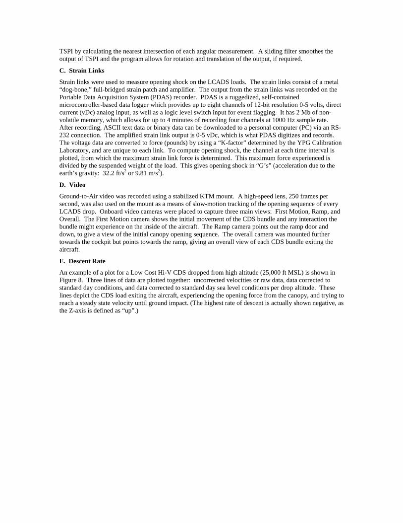
An example of a plot for a Low Cost Hi-V CDS dropped from high altitude (25,000 ft MSL) is shown inFigure 8. Three lines of data are plotted together: uncorrected velocities or raw data, data corrected tostandard day conditions, and data corrected to standard day sea level conditions per drop altitude. Theselines depict the CDS load exiting the aircraft, experiencing the opening force from the canopy, and trying toreach a steady state velocity until ground impact. (The highest rate of descent is actually shown negative, asthe Z-axis is defined as “up”.)
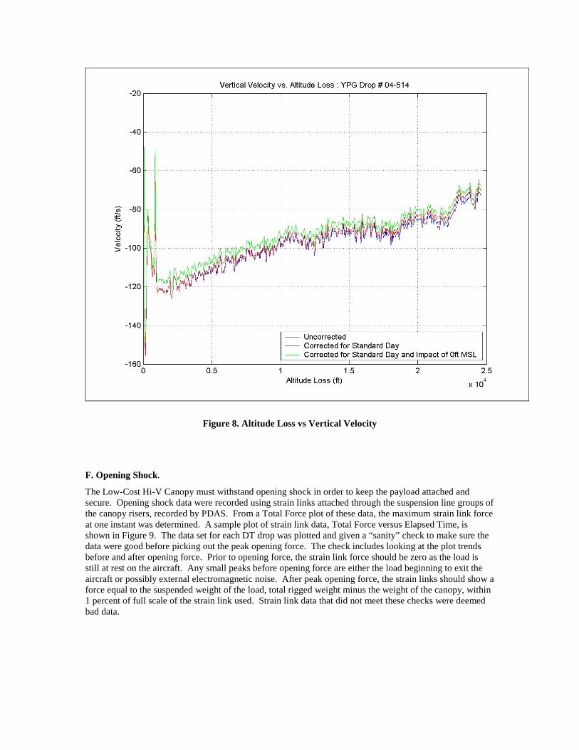
Figure 8. Altitude Loss vs Vertical Velocity
F. Opening Shock.
The Low-Cost Hi-V Canopy must withstand opening shock in order to keep the payload attached andsecure. Opening shock data were recorded using strain links attached through the suspension line groups ofthe canopy risers, recorded by PDAS. From a Total Force plot of these data, the maximum strain link forceat one instant was determined. A sample plot of strain link data, Total Force versus Elapsed Time, isshown in Figure 9. The data set for each DT drop was plotted and given a “sanity” check to make sure thedata were good before picking out the peak opening force. The check includes looking at the plot trendsbefore and after opening force. Prior to opening force, the strain link force should be zero as the load isstill at rest on the aircraft. Any small peaks before opening force are either the load beginning to exit theaircraft or possibly external electromagnetic noise. After peak opening force, the strain links should show aforce equal to the suspended weight of the load, total rigged weight minus the weight of the canopy, within1 percent of full scale of the strain link used. Strain link data that did not meet these checks were deemedbad data.

FIGURE 9. OPENING SHOCK OF THE HIGH ‘V’ PARACHUTE
G. CONCLUSIONThe LCADS Low-Cost Hi-V Canopy met the objectives of all subtests and is suitable for operational
testing. All LCADS DT Phase 2 Low-Cost High-V Canopies were verified for field readiness conditionprior to airdrop. The Low-Cost High-V Chute met the load capacity criteria of 2200 pounds (lbs), iscompatible with U.S. Air Force (USAF) cargo aircraft, is operationally suitable to be dropped from 25,000ft, can survive ground impact at high velocities, is capable of delivering a serviceable load in greater than13-knot ground winds, and meets the specifications of 0.92 reliability at 80 percent confidence and 0.85probability of airdrop completion without the occurrence of an Essential Function Failure.
VII References1Robyn Moskowitz , “Developmental Test of the Low-Cost Aerial Delivery System: Low-Cost HighVelocity Parachute, LCADS Phase 2 of 3”, Final Test Report YPG # 05-013-L5, Yuma Test Center, YumaAZ, Feb 2005
![O No Stitching [Single laver suit only] Stitching Styles Stitching ...hotshoeracewear.com/wp-content/uploads/2018/12/Suit-Order-form-… · [Single laver suit only] Stitching Styles](https://img.pdfslide.us/doc/110x75/5ed667d875f83015187a9121/o-no-stitching-single-laver-suit-only-stitching-styles-stitching-single-laver.jpg)