Embed Size (px)
Citation preview
DESIGN AND
CONSTRUCTION
OF STEEL TRANSIT
BRIDGE
STRUCTURES IN
THE CONTEXT OF
A LARGE DESIGN-
BUILD PROJECT
GREGORY H. SHAFER, PE
J. ROSS BURHOUSE, PE
BIOGRAPHY
Greg Shafer is a Bridge
Technical Manager for Parsons
and has been working in the
field of bridge design and
construction for 32 years. Mr.
Shafer graduated Magna Cum
Laude from the University of
Delaware with a Bachelor of
Science in Civil Engineering
degree and has also earned a
Master of Science Degree from
the University of Colorado. He
has been involved with
numerous large bridge projects
utilizing structural steel bridge
solution including the $650
million replacement of the
Woodrow Wilson Bridge and
the new $350 million John
James Audubon Bridge in St.
Francisville, Louisiana.
J. Ross Burhouse is a Senior
Associate in the Fairfax,
Virginia office of Dewberry,
where he has served as a bridge
engineer since 2002. Prior to
joining Dewberry he worked for
five years in the Major Bridge
Division of Parsons
Transportation Group. He holds
a Bachelor’s degree in Civil
Engineering from Princeton
University and a Master’s
degree in Civil Engineering
from the University of
Maryland. Mr. Burhouse is a
registered professional engineer
in the Commonwealth of
Virginia, and a member of the
American Society of Civil
Engineers and Sigma Xi
Society.
SUMMARY
The Dulles Corridor Metrorail
Phase 2A or Silver Line is an
extension of the Washington,
DC Metro system from Reston
to Loudoun County, Virginia
including a station at Dulles
Airport. The alignment of the
guideway generally falls in the
median of the Dulles
International Airport Access
Highway (DIAAH) on the east
side of the airport and the
median of the Dulles Greenway
on the north side of the airport.
Due to severe limitations on the
track profile and clearance over
existing roads in the median of
the DIAAH, ballasted steel
through-girder structures were
utilized to span Centerville
Road and Horsepen Run. The
through-girder design provided
a sufficiently rigid structure to
meet the strict vibration criteria
as well as the other operational
requirements for the facility,
with a structural depth of just 30
inches below the ballast.
An additional bridge over Broad
Run was built in the narrow
median of the Greenway on the
north side of Dulles Airport.
With two existing highway
bridges already crossing stream,
there was just 2 feet clear on
either side of the new transit
bridge to the highway bridges.
This necessitated a structural
scheme that could accommodate
the existing bridges in erection
of the transit bridge girders.
The details of the design and
construction of these unique
transportation structures will be
discussed in the context of the
design-build contract in which
they were executed.
Page 1 of 11
DESIGN AND CONSTRUCTION OF STEEL TRANSIT
BRIDGE STRUCTURES IN THE CONTEXT OF A LARGE
DESIGN-BUILD PROJECT
Introduction
The Metropolitan Washington Airports Authority
(MWAA) is constructing the 23-mile Silver Line
extension of the existing Metrorail system, which
will be operated by the Washington Metropolitan
Area Transit Authority (WMATA) in Northern
Virginia from East Falls Church to Washington
Dulles International Airport west to Ashburn.
Dulles Airport was constructed in the early 1960’s in
Northern Virginia, 30 miles west of Washington DC.
While the city has had the WMATA Metro system
for a long time, the train did not go to Dulles
Airport. The Silver Line now makes this connection
to the airport and the growing suburbs beyond.
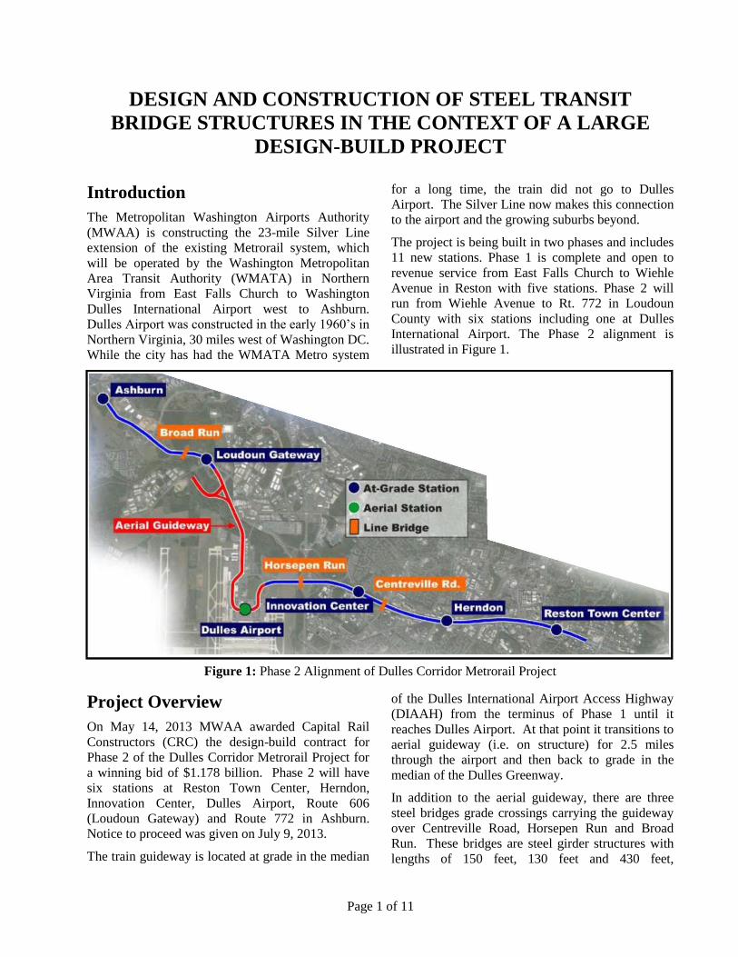
The project is being built in two phases and includes
11 new stations. Phase 1 is complete and open to
revenue service from East Falls Church to Wiehle
Avenue in Reston with five stations. Phase 2 will
run from Wiehle Avenue to Rt. 772 in Loudoun
County with six stations including one at Dulles
International Airport. The Phase 2 alignment is
illustrated in Figure 1.
Figure 1: Phase 2 Alignment of Dulles Corridor Metrorail Project
Project Overview
On May 14, 2013 MWAA awarded Capital Rail
Constructors (CRC) the design-build contract for
Phase 2 of the Dulles Corridor Metrorail Project for
a winning bid of $1.178 billion. Phase 2 will have
six stations at Reston Town Center, Herndon,
Innovation Center, Dulles Airport, Route 606
(Loudoun Gateway) and Route 772 in Ashburn.
Notice to proceed was given on July 9, 2013.
The train guideway is located at grade in the median
of the Dulles International Airport Access Highway
(DIAAH) from the terminus of Phase 1 until it
reaches Dulles Airport. At that point it transitions to
aerial guideway (i.e. on structure) for 2.5 miles
through the airport and then back to grade in the
median of the Dulles Greenway.
In addition to the aerial guideway, there are three
steel bridges grade crossings carrying the guideway
over Centreville Road, Horsepen Run and Broad
Run. These bridges are steel girder structures with
lengths of 150 feet, 130 feet and 430 feet,
Page 2 of 11
respectively, each with its own unique requirements
and configuration.
As part of the RFP, MWAA provided Preliminary
Engineering (PE) drawings which had been
developed prior to putting the project out to bid. The
PE drawings presented a possible solution to
meeting the project technical requirements. In
response to the RFP, the Design-Build team
proposed its own unique design which differed in
some aspects from the PE concepts. A particular
challenge to the Design-Build team was to obtain
buy-in from the various stakeholders on final design
concepts which departed from the PE drawings. To
address specific technical challenges and arrive at a
cost-effective solution that satisfied project
requirements, the structure types chosen in the final
design of the bridges over Centreville Road and
Horsepen Run varied significantly from the PE
designs.
At Centreville Road and Horsepen Run, proposed
steel thru-girders provide the required vertical
clearance over the road or stream while reducing the
elevation of the track profile compared to the PE
design. This resulted in significant savings for the
retaining walls of the at-grade approaches to the
bridges. It also eliminated a pier in the median of
Centreville Road that would have had to been added
at a future date when Centreville Road is widened.
The third bridge is a conventional skewed three-span
plate girder with composite deck slab founded on
drilled shafts in the Broad Run floodplain.
Design Requirements
General Rapid Transit Vehicle
Clearances to Fixed Features
The configuration of each bridge is defined to meet
general operational requirements of WMATA. The
width of the structures is defined by three clearance
requirements:
Vehicle dynamic clearance envelopes
Maintenance clearance in the track bed, and
Safety walk clearances to provide for safe
maintenance access and emergency egress.
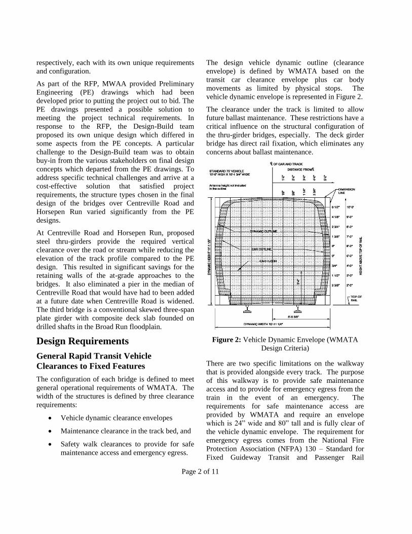
The design vehicle dynamic outline (clearance
envelope) is defined by WMATA based on the
transit car clearance envelope plus car body
movements as limited by physical stops. The
vehicle dynamic envelope is represented in Figure 2.
The clearance under the track is limited to allow
future ballast maintenance. These restrictions have a
critical influence on the structural configuration of
the thru-girder bridges, especially. The deck girder
bridge has direct rail fixation, which eliminates any
concerns about ballast maintenance.
Figure 2: Vehicle Dynamic Envelope (WMATA
Design Criteria)
There are two specific limitations on the walkway
that is provided alongside every track. The purpose
of this walkway is to provide safe maintenance
access and to provide for emergency egress from the
train in the event of an emergency. The
requirements for safe maintenance access are
provided by WMATA and require an envelope
which is 24” wide and 80” tall and is fully clear of
the vehicle dynamic envelope. The requirement for
emergency egress comes from the National Fire
Protection Association (NFPA) 130 – Standard for
Fixed Guideway Transit and Passenger Rail
Page 3 of 11
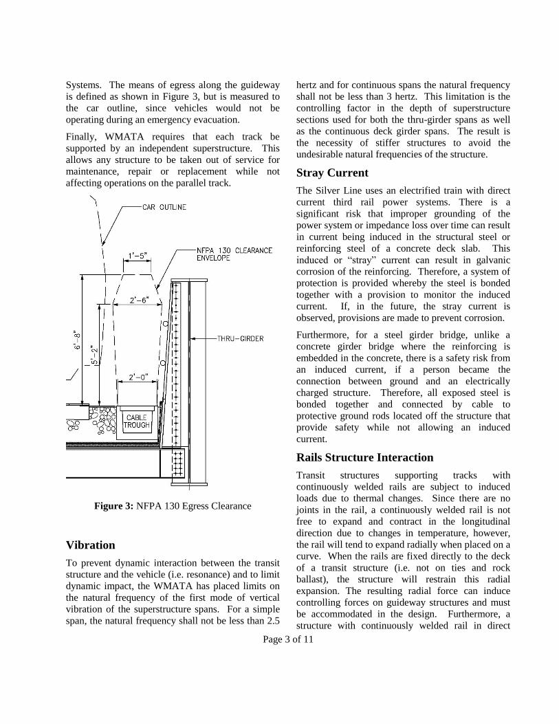
Systems. The means of egress along the guideway
is defined as shown in Figure 3, but is measured to
the car outline, since vehicles would not be
operating during an emergency evacuation.
Finally, WMATA requires that each track be
supported by an independent superstructure. This
allows any structure to be taken out of service for
maintenance, repair or replacement while not
affecting operations on the parallel track.
Figure 3: NFPA 130 Egress Clearance
Vibration
To prevent dynamic interaction between the transit
structure and the vehicle (i.e. resonance) and to limit
dynamic impact, the WMATA has placed limits on
the natural frequency of the first mode of vertical
vibration of the superstructure spans. For a simple
span, the natural frequency shall not be less than 2.5
hertz and for continuous spans the natural frequency
shall not be less than 3 hertz. This limitation is the
controlling factor in the depth of superstructure
sections used for both the thru-girder spans as well
as the continuous deck girder spans. The result is
the necessity of stiffer structures to avoid the
undesirable natural frequencies of the structure.
Stray Current
The Silver Line uses an electrified train with direct
current third rail power systems. There is a
significant risk that improper grounding of the
power system or impedance loss over time can result
in current being induced in the structural steel or
reinforcing steel of a concrete deck slab. This
induced or “stray” current can result in galvanic
corrosion of the reinforcing. Therefore, a system of
protection is provided whereby the steel is bonded
together with a provision to monitor the induced
current. If, in the future, the stray current is
observed, provisions are made to prevent corrosion.
Furthermore, for a steel girder bridge, unlike a
concrete girder bridge where the reinforcing is
embedded in the concrete, there is a safety risk from
an induced current, if a person became the
connection between ground and an electrically
charged structure. Therefore, all exposed steel is
bonded together and connected by cable to
protective ground rods located off the structure that
provide safety while not allowing an induced
current.
Rails Structure Interaction
Transit structures supporting tracks with
continuously welded rails are subject to induced
loads due to thermal changes. Since there are no
joints in the rail, a continuously welded rail is not
free to expand and contract in the longitudinal
direction due to changes in temperature, however,
the rail will tend to expand radially when placed on a
curve. When the rails are fixed directly to the deck
of a transit structure (i.e. not on ties and rock
ballast), the structure will restrain this radial
expansion. The resulting radial force can induce
controlling forces on guideway structures and must
be accommodated in the design. Furthermore, a
structure with continuously welded rail in direct
Page 4 of 11
fixation must account for the possibility that a rail
may break somewhere along the length of the bridge
during the service life of the structure. The stresses
in the rail are maximum at the bridge expansion
joints and are most critical under extreme cold
temperatures. When a rail breaks, it is free to
contract in the longitudinal direction. It is necessary
to restrain this contraction to prevent a large gap at
the break location which could induce a derailment
of the train. The contraction is limited by the use of
limited slip rail fasteners that provide some restraint
to the free slippage of the rail. However, this
restraint induces forces in the structure which could
cause damage to the piers and foundations without
proper consideration.
Utilities
Each of the transit structures considered here support
the electrical distribution lines that supply power to
the substations provided along the guideway to
provide power for the trains. These 34.5 kV AC
current powerlines are supported in 8” diameter
conduits along the girders. The general public must
be protected from the shock hazard presented by
these electrical lines, so the lines are encased in
fiberglass conduits where exposed above ground.
As well, the transition from buried ductbank to
exposed ductbank along girders required careful
consideration to prevent damage to the electrical
system due to settlement or thermal movement.
Centreville Road Bridge A key design requirement at this site was for the
Metrorail bridge to accommodate the future cross-
section of Centreville Road. The adjacent highway
bridges over Centreville Road feature 100 foot long
single spans with pile supported abutments behind
Mechanically Stabilized Earth (MSE) walls. Rather
than matching the existing bridge lengths, the
Metrorail bridge was required to span a clear
opening of over 141 feet to accommodate future
improvements to Centreville Road and a bike trail
planned by Fairfax County. Furthermore the
abutments needed to be independent of the existing
MSE wall system which will ultimately be removed
for the future widening of Centreville Road.
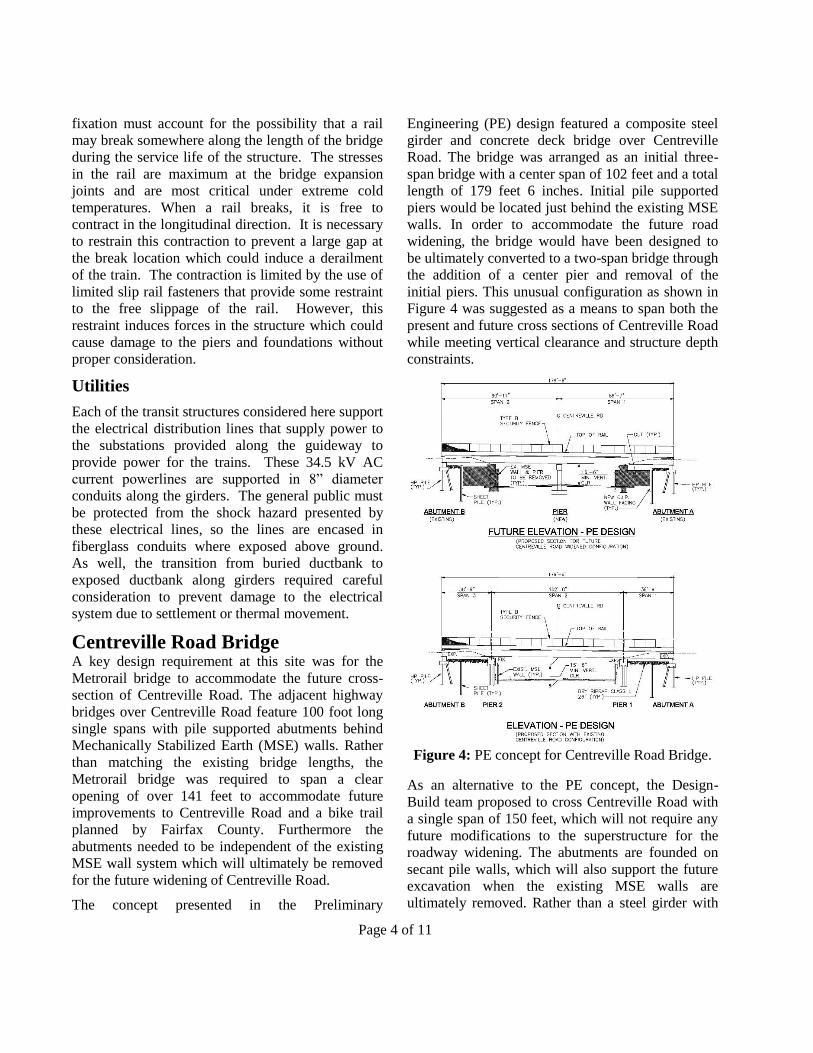
The concept presented in the Preliminary
Engineering (PE) design featured a composite steel
girder and concrete deck bridge over Centreville
Road. The bridge was arranged as an initial three-
span bridge with a center span of 102 feet and a total
length of 179 feet 6 inches. Initial pile supported
piers would be located just behind the existing MSE
walls. In order to accommodate the future road
widening, the bridge would have been designed to
be ultimately converted to a two-span bridge through
the addition of a center pier and removal of the
initial piers. This unusual configuration as shown in
Figure 4 was suggested as a means to span both the
present and future cross sections of Centreville Road
while meeting vertical clearance and structure depth
constraints.
Figure 4: PE concept for Centreville Road Bridge.
As an alternative to the PE concept, the Design-
Build team proposed to cross Centreville Road with
a single span of 150 feet, which will not require any
future modifications to the superstructure for the
roadway widening. The abutments are founded on
secant pile walls, which will also support the future
excavation when the existing MSE walls are
ultimately removed. Rather than a steel girder with
Page 5 of 11
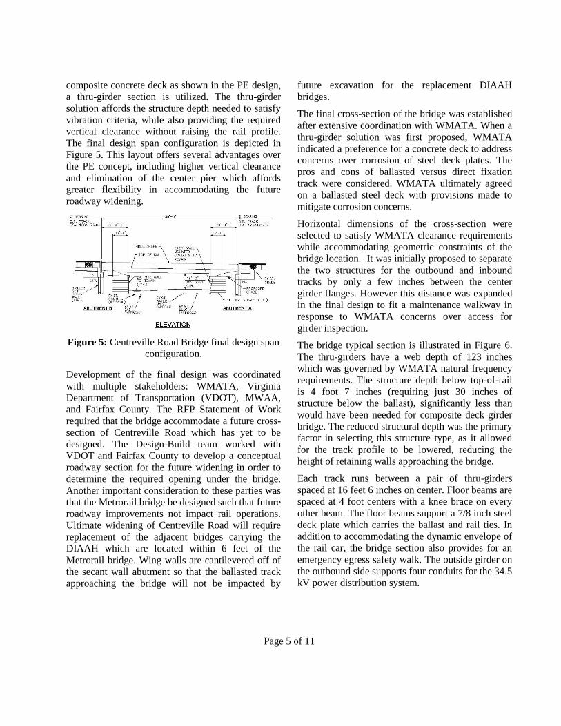
composite concrete deck as shown in the PE design,
a thru-girder section is utilized. The thru-girder
solution affords the structure depth needed to satisfy
vibration criteria, while also providing the required
vertical clearance without raising the rail profile.
The final design span configuration is depicted in
Figure 5. This layout offers several advantages over
the PE concept, including higher vertical clearance
and elimination of the center pier which affords
greater flexibility in accommodating the future
roadway widening.
Figure 5: Centreville Road Bridge final design span
configuration.
Development of the final design was coordinated
with multiple stakeholders: WMATA, Virginia
Department of Transportation (VDOT), MWAA,
and Fairfax County. The RFP Statement of Work
required that the bridge accommodate a future cross-
section of Centreville Road which has yet to be
designed. The Design-Build team worked with
VDOT and Fairfax County to develop a conceptual
roadway section for the future widening in order to
determine the required opening under the bridge.
Another important consideration to these parties was
that the Metrorail bridge be designed such that future
roadway improvements not impact rail operations.
Ultimate widening of Centreville Road will require
replacement of the adjacent bridges carrying the
DIAAH which are located within 6 feet of the
Metrorail bridge. Wing walls are cantilevered off of
the secant wall abutment so that the ballasted track
approaching the bridge will not be impacted by
future excavation for the replacement DIAAH
bridges.
The final cross-section of the bridge was established
after extensive coordination with WMATA. When a
thru-girder solution was first proposed, WMATA
indicated a preference for a concrete deck to address
concerns over corrosion of steel deck plates. The
pros and cons of ballasted versus direct fixation
track were considered. WMATA ultimately agreed
on a ballasted steel deck with provisions made to
mitigate corrosion concerns.
Horizontal dimensions of the cross-section were
selected to satisfy WMATA clearance requirements
while accommodating geometric constraints of the
bridge location. It was initially proposed to separate
the two structures for the outbound and inbound
tracks by only a few inches between the center
girder flanges. However this distance was expanded
in the final design to fit a maintenance walkway in
response to WMATA concerns over access for
girder inspection.
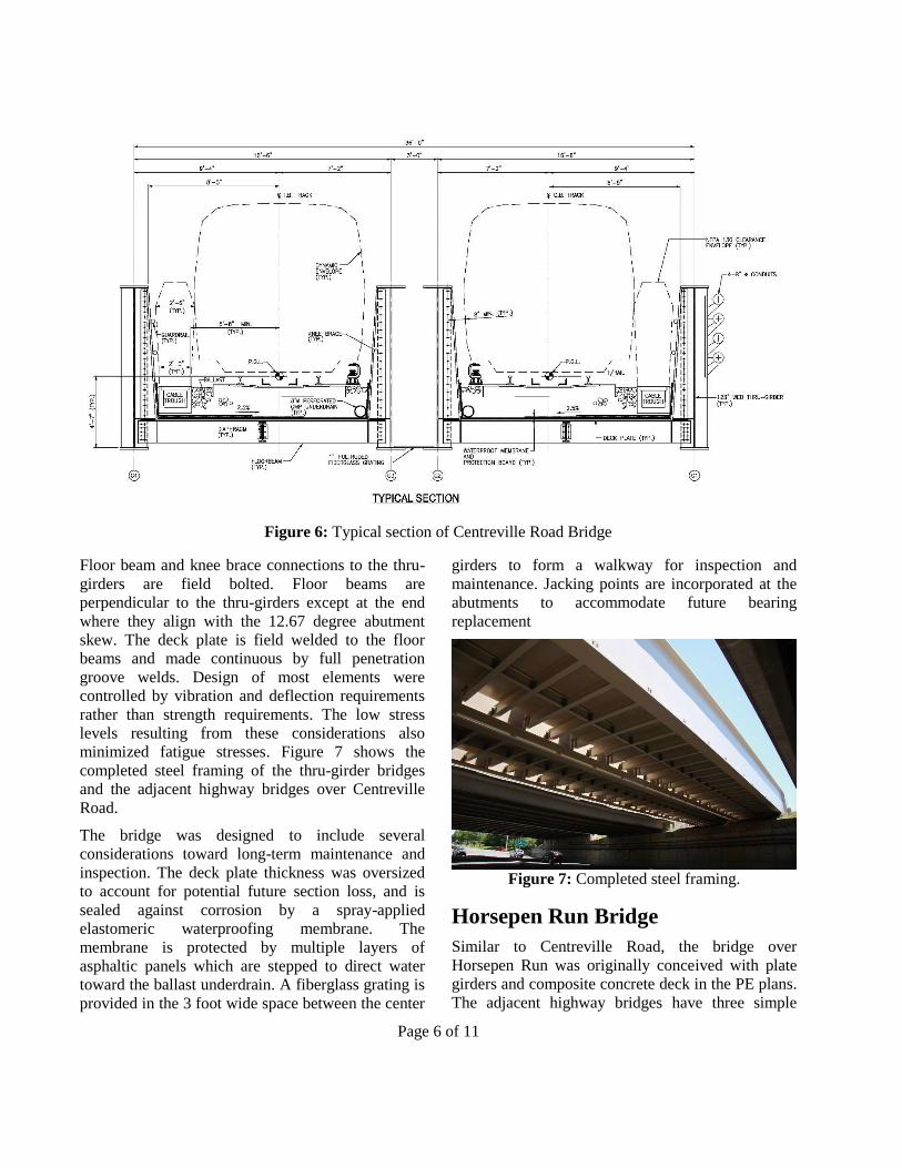
The bridge typical section is illustrated in Figure 6.
The thru-girders have a web depth of 123 inches
which was governed by WMATA natural frequency
requirements. The structure depth below top-of-rail
is 4 foot 7 inches (requiring just 30 inches of
structure below the ballast), significantly less than
would have been needed for composite deck girder
bridge. The reduced structural depth was the primary
factor in selecting this structure type, as it allowed
for the track profile to be lowered, reducing the
height of retaining walls approaching the bridge.
Each track runs between a pair of thru-girders
spaced at 16 feet 6 inches on center. Floor beams are
spaced at 4 foot centers with a knee brace on every
other beam. The floor beams support a 7/8 inch steel
deck plate which carries the ballast and rail ties. In
addition to accommodating the dynamic envelope of
the rail car, the bridge section also provides for an
emergency egress safety walk. The outside girder on
the outbound side supports four conduits for the 34.5
kV power distribution system.
Page 6 of 11
Figure 6: Typical section of Centreville Road Bridge
Floor beam and knee brace connections to the thru-
girders are field bolted. Floor beams are
perpendicular to the thru-girders except at the end
where they align with the 12.67 degree abutment
skew. The deck plate is field welded to the floor
beams and made continuous by full penetration
groove welds. Design of most elements were
controlled by vibration and deflection requirements
rather than strength requirements. The low stress
levels resulting from these considerations also
minimized fatigue stresses. Figure 7 shows the
completed steel framing of the thru-girder bridges
and the adjacent highway bridges over Centreville
Road.
The bridge was designed to include several
considerations toward long-term maintenance and
inspection. The deck plate thickness was oversized
to account for potential future section loss, and is
sealed against corrosion by a spray-applied
elastomeric waterproofing membrane. The
membrane is protected by multiple layers of
asphaltic panels which are stepped to direct water
toward the ballast underdrain. A fiberglass grating is
provided in the 3 foot wide space between the center
girders to form a walkway for inspection and
maintenance. Jacking points are incorporated at the
abutments to accommodate future bearing
replacement
Figure 7: Completed steel framing.
Horsepen Run Bridge
Similar to Centreville Road, the bridge over
Horsepen Run was originally conceived with plate
girders and composite concrete deck in the PE plans.
The adjacent highway bridges have three simple
Page 7 of 11
spans with a center span of 60 feet and two side
spans of 35 foot 5 inches each. The PE plans showed
the same span lengths for the Metrorail bridge. Once
the Design-Build team developed the thru-girder
concept for Centreville Road, it was decided to use
the same structural type at Horsepen Run. A thru-
girder bridge at Horsepen Run allows for the stream
to be crossed with a single span of 130 feet 10
inches and eliminates the need for any piers. Over 5
feet of freeboard is provided over the 100 year flood
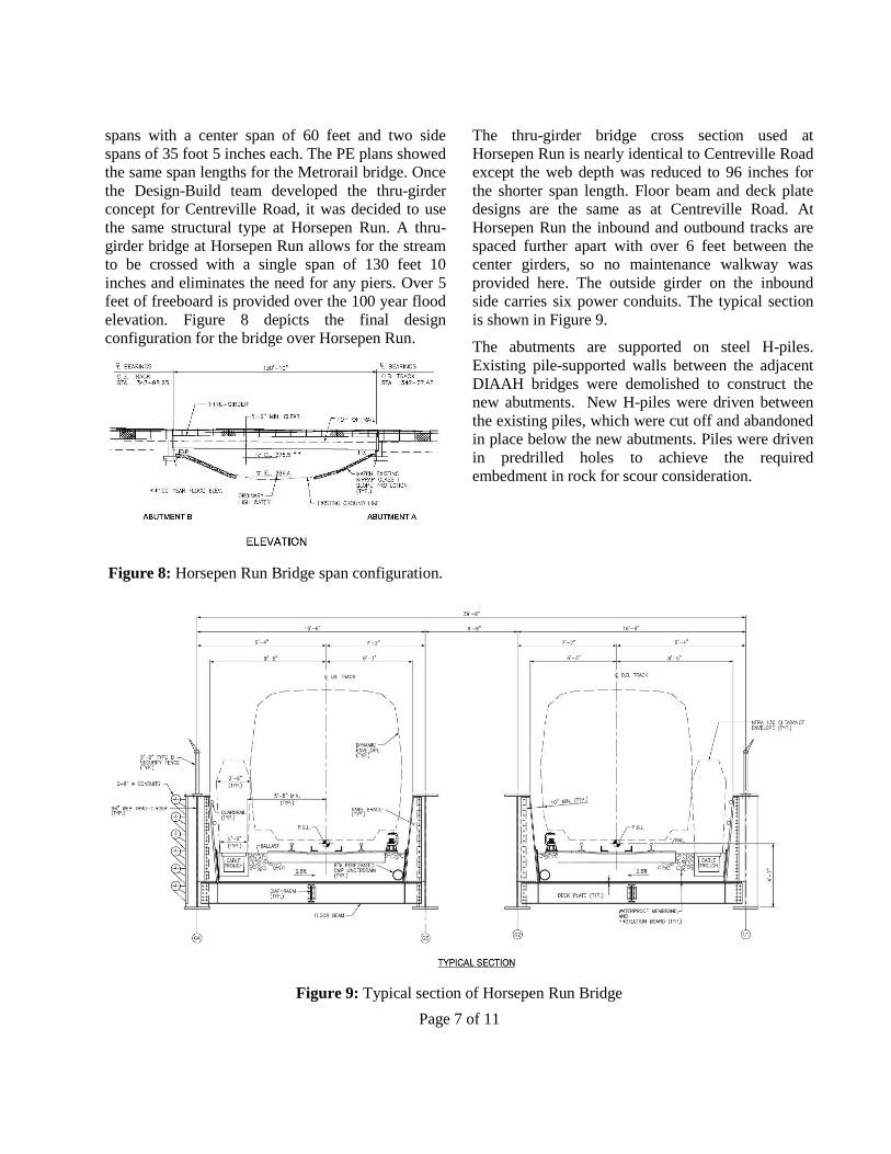
elevation. Figure 8 depicts the final design
configuration for the bridge over Horsepen Run.
Figure 8: Horsepen Run Bridge span configuration.
The thru-girder bridge cross section used at
Horsepen Run is nearly identical to Centreville Road
except the web depth was reduced to 96 inches for
the shorter span length. Floor beam and deck plate
designs are the same as at Centreville Road. At
Horsepen Run the inbound and outbound tracks are
spaced further apart with over 6 feet between the
center girders, so no maintenance walkway was
provided here. The outside girder on the inbound
side carries six power conduits. The typical section
is shown in Figure 9.
The abutments are supported on steel H-piles.
Existing pile-supported walls between the adjacent
DIAAH bridges were demolished to construct the
new abutments. New H-piles were driven between
the existing piles, which were cut off and abandoned
in place below the new abutments. Piles were driven
in predrilled holes to achieve the required
embedment in rock for scour consideration.
Figure 9: Typical section of Horsepen Run Bridge
Page 8 of 11
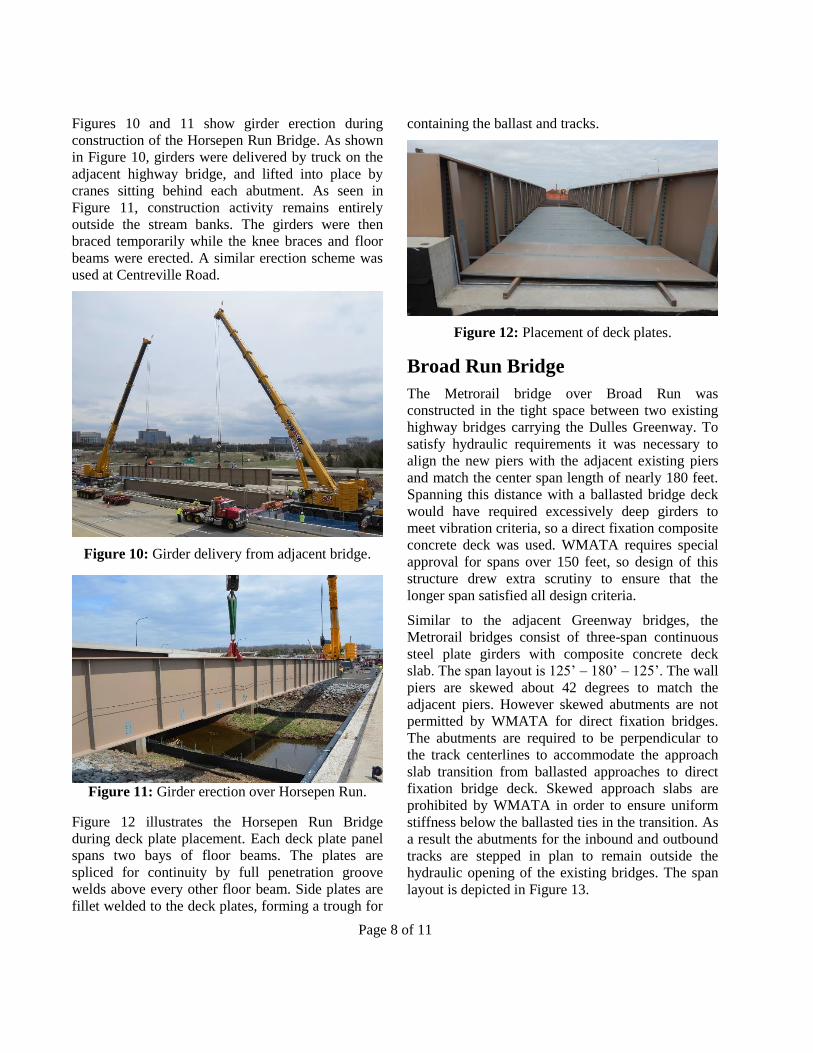
Figures 10 and 11 show girder erection during
construction of the Horsepen Run Bridge. As shown
in Figure 10, girders were delivered by truck on the
adjacent highway bridge, and lifted into place by
cranes sitting behind each abutment. As seen in
Figure 11, construction activity remains entirely
outside the stream banks. The girders were then
braced temporarily while the knee braces and floor
beams were erected. A similar erection scheme was
used at Centreville Road.
Figure 10: Girder delivery from adjacent bridge.
Figure 11: Girder erection over Horsepen Run.
Figure 12 illustrates the Horsepen Run Bridge
during deck plate placement. Each deck plate panel
spans two bays of floor beams. The plates are
spliced for continuity by full penetration groove
welds above every other floor beam. Side plates are
fillet welded to the deck plates, forming a trough for
containing the ballast and tracks.
Figure 12: Placement of deck plates.
Broad Run Bridge
The Metrorail bridge over Broad Run was
constructed in the tight space between two existing
highway bridges carrying the Dulles Greenway. To
satisfy hydraulic requirements it was necessary to
align the new piers with the adjacent existing piers
and match the center span length of nearly 180 feet.
Spanning this distance with a ballasted bridge deck
would have required excessively deep girders to
meet vibration criteria, so a direct fixation composite
concrete deck was used. WMATA requires special
approval for spans over 150 feet, so design of this
structure drew extra scrutiny to ensure that the
longer span satisfied all design criteria.
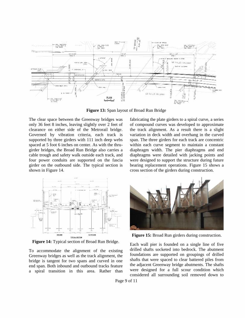
Similar to the adjacent Greenway bridges, the
Metrorail bridges consist of three-span continuous
steel plate girders with composite concrete deck
slab. The span layout is 125’ – 180’ – 125’. The wall
piers are skewed about 42 degrees to match the
adjacent piers. However skewed abutments are not
permitted by WMATA for direct fixation bridges.
The abutments are required to be perpendicular to
the track centerlines to accommodate the approach
slab transition from ballasted approaches to direct
fixation bridge deck. Skewed approach slabs are
prohibited by WMATA in order to ensure uniform
stiffness below the ballasted ties in the transition. As
a result the abutments for the inbound and outbound
tracks are stepped in plan to remain outside the
hydraulic opening of the existing bridges. The span
layout is depicted in Figure 13.
Page 9 of 11
Figure 13: Span layout of Broad Run Bridge
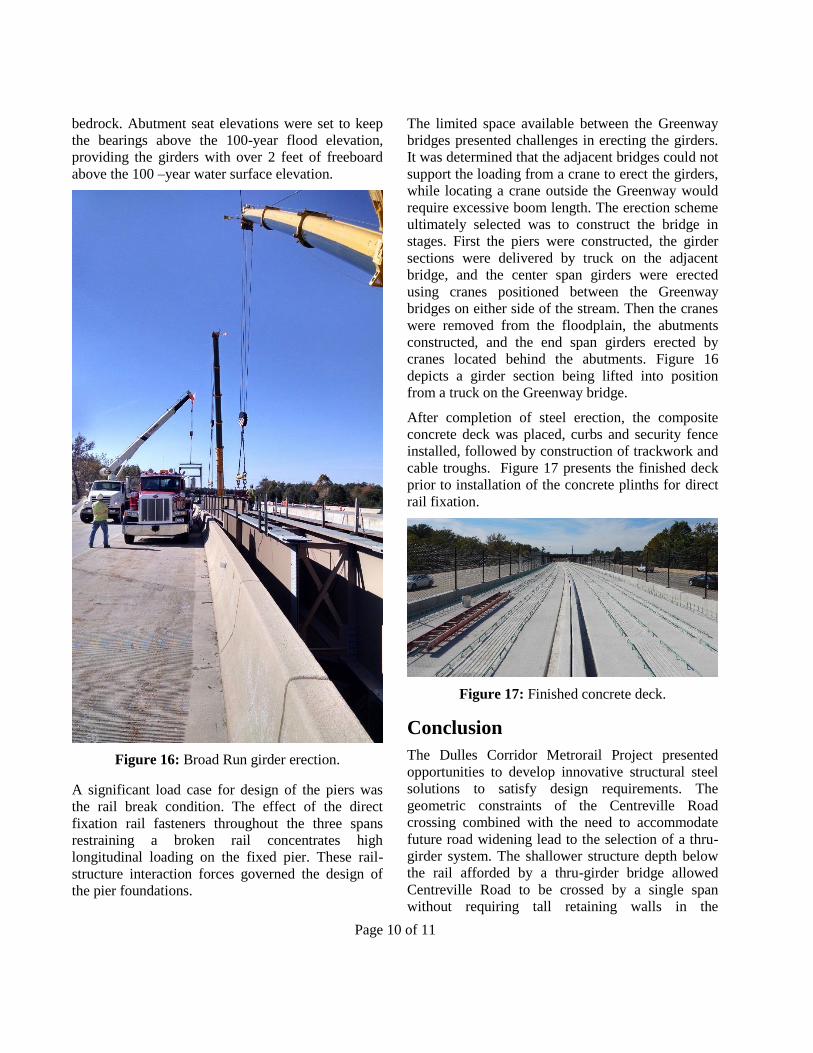
The clear space between the Greenway bridges was
only 36 feet 8 inches, leaving slightly over 2 feet of
clearance on either side of the Metrorail bridge.
Governed by vibration criteria, each track is
supported by three girders with 111 inch deep webs
spaced at 5 foot 6 inches on center. As with the thru-
girder bridges, the Broad Run Bridge also carries a
cable trough and safety walk outside each track, and
four power conduits are supported on the fascia
girder on the outbound side. The typical section is
shown in Figure 14.
Figure 14: Typical section of Broad Run Bridge.
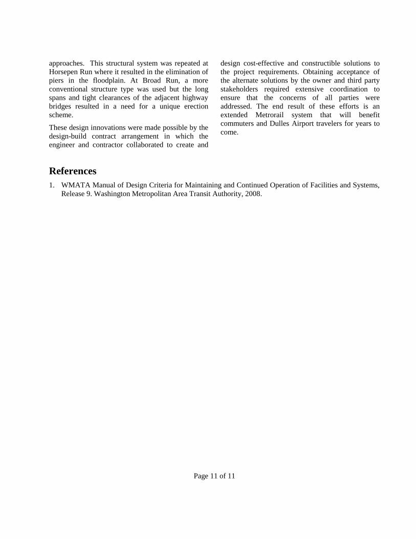
To accommodate the alignment of the existing
Greenway bridges as well as the track alignment, the
bridge is tangent for two spans and curved in one
end span. Both inbound and outbound tracks feature
a spiral transition in this area. Rather than
fabricating the plate girders to a spiral curve, a series
of compound curves was developed to approximate
the track alignment. As a result there is a slight
variation in deck width and overhang in the curved
span. The three girders for each track are concentric
within each curve segment to maintain a constant
diaphragm width. The pier diaphragms and end
diaphragms were detailed with jacking points and
were designed to support the structure during future
bearing replacement operations. Figure 15 shows a
cross section of the girders during construction.
Figure 15: Broad Run girders during construction.
Each wall pier is founded on a single line of five
drilled shafts socketed into bedrock. The abutment
foundations are supported on groupings of drilled
shafts that were spaced to clear battered piles from
the adjacent Greenway bridge abutments. The shafts
were designed for a full scour condition which
considered all surrounding soil removed down to
Page 10 of 11
bedrock. Abutment seat elevations were set to keep
the bearings above the 100-year flood elevation,
providing the girders with over 2 feet of freeboard
above the 100 –year water surface elevation.
Figure 16: Broad Run girder erection.
A significant load case for design of the piers was
the rail break condition. The effect of the direct
fixation rail fasteners throughout the three spans
restraining a broken rail concentrates high
longitudinal loading on the fixed pier. These rail-
structure interaction forces governed the design of
the pier foundations.
The limited space available between the Greenway
bridges presented challenges in erecting the girders.
It was determined that the adjacent bridges could not
support the loading from a crane to erect the girders,
while locating a crane outside the Greenway would
require excessive boom length. The erection scheme
ultimately selected was to construct the bridge in
stages. First the piers were constructed, the girder
sections were delivered by truck on the adjacent
bridge, and the center span girders were erected
using cranes positioned between the Greenway
bridges on either side of the stream. Then the cranes
were removed from the floodplain, the abutments
constructed, and the end span girders erected by
cranes located behind the abutments. Figure 16
depicts a girder section being lifted into position
from a truck on the Greenway bridge.
After completion of steel erection, the composite
concrete deck was placed, curbs and security fence
installed, followed by construction of trackwork and
cable troughs. Figure 17 presents the finished deck
prior to installation of the concrete plinths for direct
rail fixation.
Figure 17: Finished concrete deck.
Conclusion
The Dulles Corridor Metrorail Project presented
opportunities to develop innovative structural steel
solutions to satisfy design requirements. The
geometric constraints of the Centreville Road
crossing combined with the need to accommodate
future road widening lead to the selection of a thru-
girder system. The shallower structure depth below
the rail afforded by a thru-girder bridge allowed
Centreville Road to be crossed by a single span
without requiring tall retaining walls in the
Page 11 of 11
approaches. This structural system was repeated at
Horsepen Run where it resulted in the elimination of
piers in the floodplain. At Broad Run, a more
conventional structure type was used but the long
spans and tight clearances of the adjacent highway
bridges resulted in a need for a unique erection
scheme.
These design innovations were made possible by the
design-build contract arrangement in which the
engineer and contractor collaborated to create and
design cost-effective and constructible solutions to
the project requirements. Obtaining acceptance of
the alternate solutions by the owner and third party
stakeholders required extensive coordination to
ensure that the concerns of all parties were
addressed. The end result of these efforts is an
extended Metrorail system that will benefit
commuters and Dulles Airport travelers for years to
come.
References
1. WMATA Manual of Design Criteria for Maintaining and Continued Operation of Facilities and Systems,
Release 9. Washington Metropolitan Area Transit Authority, 2008.