Embed Size (px)
Citation preview
Small Bridges Conference, Melbourne, Victoria, 2015
P a g e 1 | 15
DESIGN AND CONSTRUCTION OF PURLING BROOK FALLS
SUSPENSION BRIDGE (JOHN STACEY BRIDGE), SPRINGBROOK
NATIONAL PARK, QLD
Antony Schofield, Arup Pty Ltd, Brisbane, Australia
ABSTRACT
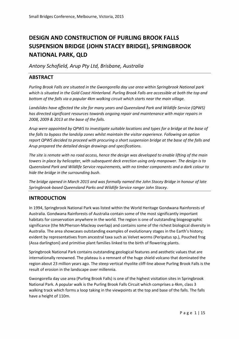
Purling Brook Falls are situated in the Gwongorella day use area within Springbrook National park
which is situated in the Gold Coast Hinterland. Purling Brook Falls are accessible at both the top and
bottom of the falls via a popular 4km walking circuit which starts near the main village.
Landslides have affected the site for many years and Queensland Park and Wildlife Service (QPWS)
has directed significant resources towards ongoing repair and maintenance with major repairs in
2008, 2009 & 2013 at the base of the falls.
Arup were appointed by QPWS to investigate suitable locations and types for a bridge at the base of
the falls to bypass the landslip zones whilst maintain the visitor experience. Following an option
report QPWS decided to proceed with procuring a short suspension bridge at the base of the falls and
Arup prepared the detailed design drawings and specifications.
The site is remote with no road access, hence the design was developed to enable lifting of the main
towers in place by helicopter, with subsequent deck erection using only manpower. The design is to
Queensland Park and Wildlife Service requirements, with no timber components and a dark colour to
hide the bridge in the surrounding bush.
The bridge opened in March 2015 and was formally named the John Stacey Bridge in honour of late
Springbrook-based Queensland Parks and Wildlife Service ranger John Stacey.
INTRODUCTION
In 1994, Springbrook National Park was listed within the World Heritage Gondwana Rainforests of
Australia. Gondwana Rainforests of Australia contain some of the most significantly important
habitats for conservation anywhere in the world. The region is one of outstanding biogeographic
significance (the McPherson-Macleay overlap) and contains some of the richest biological diversity in
Australia. The area showcases outstanding examples of evolutionary stages in the Earth’s history;
evident by representatives from ancestral taxa such as Velvet worms (Peripatus sp.), Pouched frog
(Assa darlingtoni) and primitive plant families linked to the birth of flowering plants.
Springbrook National Park contains outstanding geological features and aesthetic values that are
internationally renowned. The plateau is a remnant of the huge shield volcano that dominated the
region about 23 million years ago. The steep vertical rhyolite cliff-line above Purling Brook Falls is the
result of erosion in the landscape over millennia.
Gwongorella day use area (Purling Brook Falls) is one of the highest visitation sites in Springbrook
National Park. A popular walk is the Purling Brook Falls Circuit which comprises a 4km, class 3
walking track which forms a loop taking in the viewpoints at the top and base of the falls. The falls
have a height of 110m.
Small Bridges Conference, Melbourne, Victoria, 2015
P a g e 2 | 15
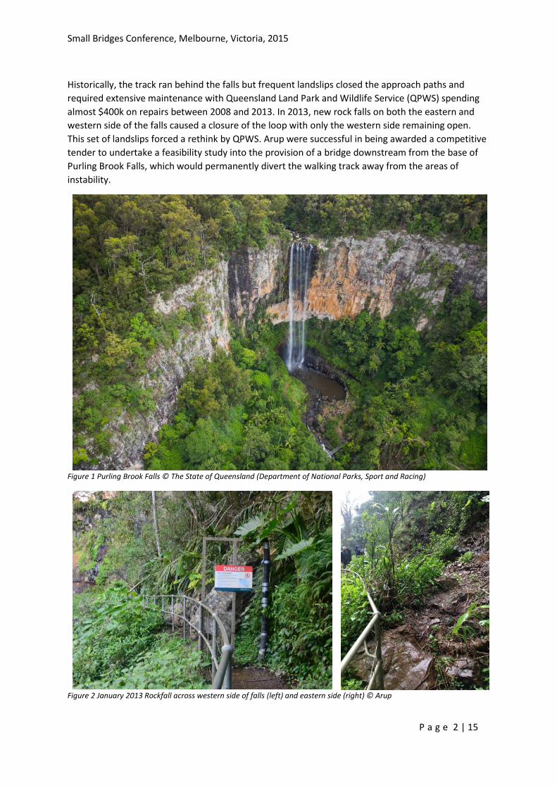
Historically, the track ran behind the falls but frequent landslips closed the approach paths and
required extensive maintenance with Queensland Land Park and Wildlife Service (QPWS) spending
almost $400k on repairs between 2008 and 2013. In 2013, new rock falls on both the eastern and
western side of the falls caused a closure of the loop with only the western side remaining open.
This set of landslips forced a rethink by QPWS. Arup were successful in being awarded a competitive
tender to undertake a feasibility study into the provision of a bridge downstream from the base of
Purling Brook Falls, which would permanently divert the walking track away from the areas of
instability.
Figure 1 Purling Brook Falls © The State of Queensland (Department of National Parks, Sport and Racing)
Figure 2 January 2013 Rockfall across western side of falls (left) and eastern side (right) © Arup
Small Bridges Conference, Melbourne, Victoria, 2015
P a g e 3 | 15
BRIDGE FEASIBILITY
The QPWS requirements for the bridge were as follows.
Determine the best site for the bridge
Determine a suitable bridge form
Establish an initial estimate of probable cost to help determine the viability of the project
Visual Amenity. Infrastructure is to be located in visual shadows wherever possible. The design
and positioning of new infrastructure will take into consideration the character of the park.
Vegetation Protection. Facilities are to be located in currently cleared and or disturbed areas.
Destruction of standing timber would not generally be accepted.
Materials. Selection of sympathetic materials for all infrastructure components is essential. The
materials should be inert, blend in with the surrounding environment and be selected for their
longevity, ease and minimisation of maintenance.
Site Character. All items of infrastructure should exhibit a common theme in sympathy with the
site character and comply with the provisions of the QPWS Facilities Manual.
Rare and Threatened Species. Facilities are not to be located where any declared rare and
threatened species of plants and animals under the Nature Conservation Act 1992 have been
recorded.
Cultural Heritage Artefacts. Facilities are not to be located in the vicinity of any sites that are
deemed cultural heritage artefacts
Water quality. The site is situated in the headwaters of the Gold Coast City Council drinking water
catchment for the Little Nerang Dam. The construction project will need to ensure adequate
precautions are undertaken to satisfy works in such a location.
QPWS Facilities Manual. This Manual is critical to the planning, design and construction of
facilities on protected area
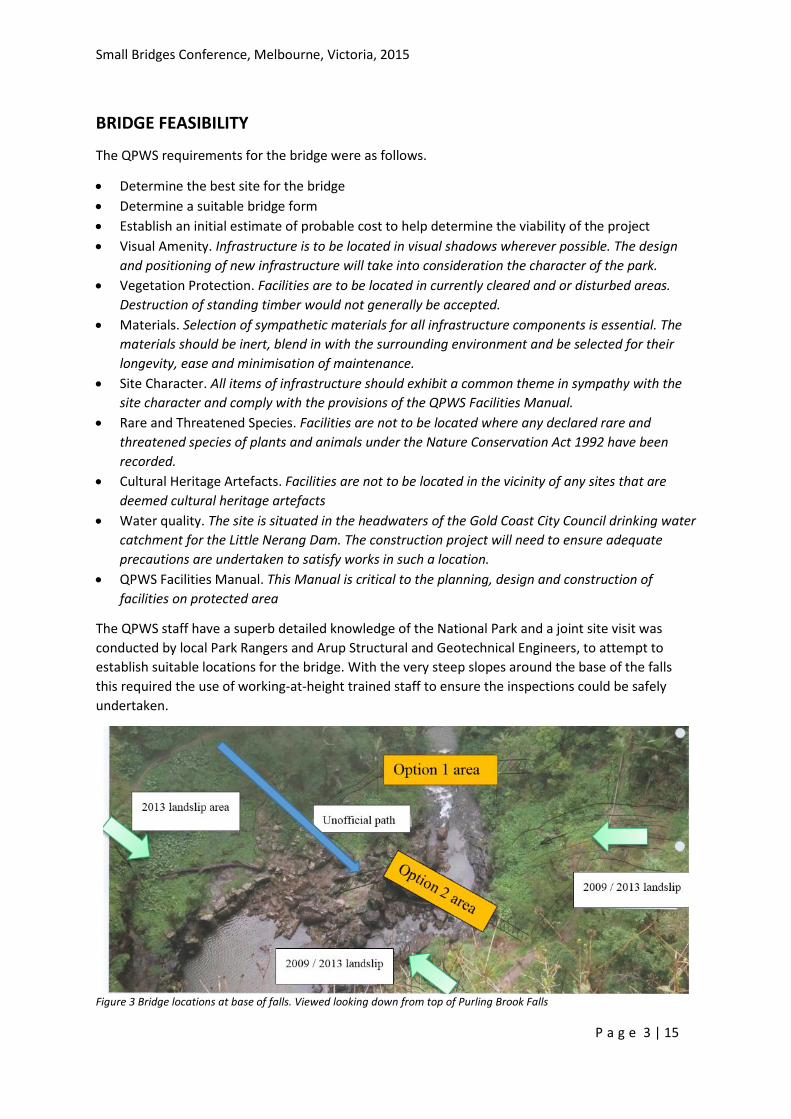
The QPWS staff have a superb detailed knowledge of the National Park and a joint site visit was
conducted by local Park Rangers and Arup Structural and Geotechnical Engineers, to attempt to
establish suitable locations for the bridge. With the very steep slopes around the base of the falls
this required the use of working-at-height trained staff to ensure the inspections could be safely
undertaken.
Figure 3 Bridge locations at base of falls. Viewed looking down from top of Purling Brook Falls
Small Bridges Conference, Melbourne, Victoria, 2015
P a g e 4 | 15
In the end two sites were identified for a potential bridge, both using an existing unofficial path to
the plunge pool. Option 1, was the preferred site downstream of the plunge pool and a backup site,
Option 2 which was closer to the exit of the plunge pool.
The preferred site offered the following advantages for a new bridge crossing.
Good anchorage options for a possible suspension bridge structure
Good foundations for general bridge supports on either side of the creek.
Sufficient clearance over the river for flood immunity
Avoided all existing landslips around the base of the falls
Good views both upstream to the existing falls but also downstream to a small falls
Reduced visual impact from rim viewpoints
The option did have the disadvantages of more difficult access to the eastern foundations,
requirement to remove 3 trees and a slightly longer approach track.
A suspension bridge structure was proposed in the option study based on similar walking tracks
structures in the Dorrigo National Park and Apsley Falls both in New South Wales. The spans of these
bridges are 40m and 56m respectively. The span at Purling Brook Falls was estimated at 30 to 40m
depending on final locations.
An alternative structural form comprising a truss bridge was also offered, since this avoided the
requirements for tension anchorages, but installation would require a much larger helicopter than
locally available.
QPWS required that no timber components were used to simplify maintenance, and that the bridge
be painted black to minimise visual impact. The preferred form of a suspension bridge structure can
be constructed from smaller components, and minimises visual impact. FRP mesh was also adopted
for the flooring.
BRIDGE DESIGN
The bridge is designed to the requirements of AS 2156.2 Walking tracks Part 2: Infrastructure design.
This requires the following loads to be considered and structural design carried out to AS 5100
Bridge Design parts 1 to 7.
4 kPa UDL
1.4 kN point loading on the flooring members
Project specific load case of 4 x 100 kg point loads which is considered to be a more likely load
case for a group standing on the bridge
A Type C barrier as defined in AS 2156.2 was agreed as the preferred option, but with mesh infill.
Initial design calculations for the suspension bridge were carried out based on a design guide
developed by Arup and the charity Bridges to Prosperity (B2P). This guide provides a generic set of
drawings and design tools for the design and construction of pedestrian suspension footbridges
between 30 and 100m spans in the developing world. It provided useful first pass estimates of cable
loads, cable sags and tower heights etc so that key dimensions could be set.
To finalise the bridge dimensions, a levelling traverse was carried out during a site visit, and was
combined with laser distance measurements backed up with tape measurements at key locations.
This enabled the bridge span to be estimated to within a meter and design levels set to a project
Small Bridges Conference, Melbourne, Victoria, 2015
P a g e 5 | 15
datum. The bridge was then designed for a significant variation in length, and the drawings detailed
such that once the successful contractor arrived on site and cleared away vegetation, the final
dimensions could be locked in without requirements to change the structural design.
Vertical alignment
A key early design decision was to adopt either a flat or curved deck profile. Providing a flat profile
would require adjustable hangers and cause significant issues with adjustment of the structure after
it was constructed, since any residual sag would be clearly visible to visitors.
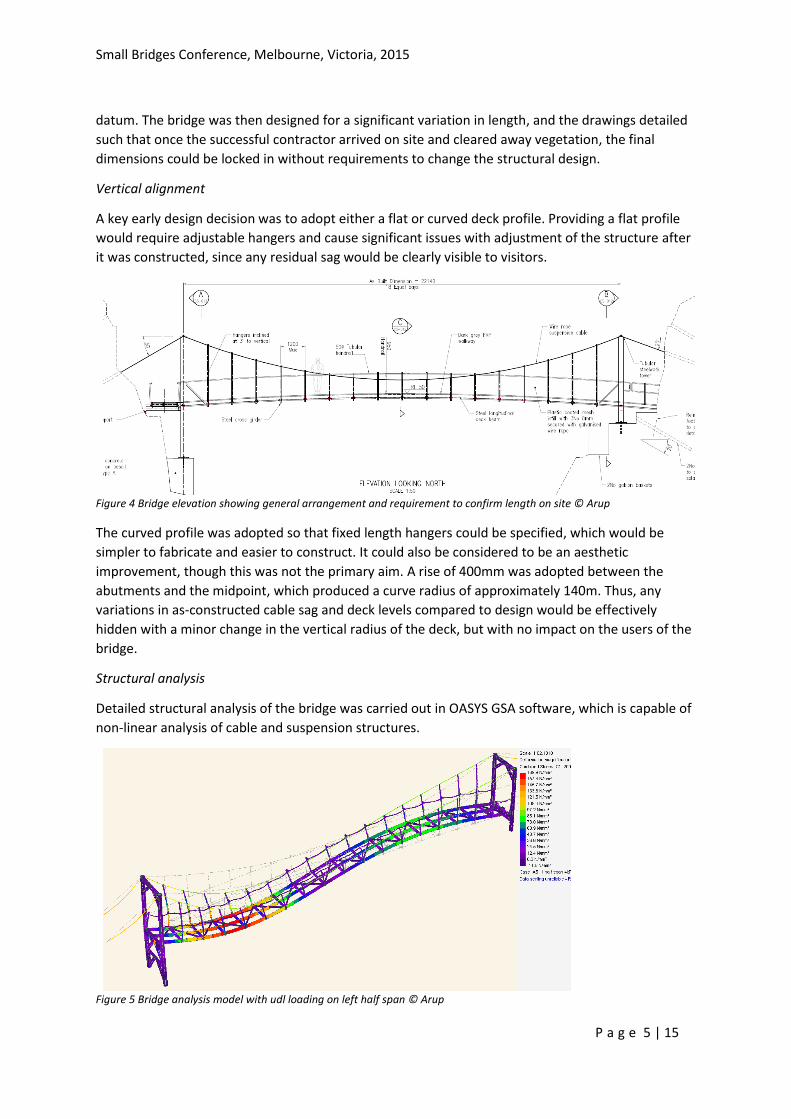
Figure 4 Bridge elevation showing general arrangement and requirement to confirm length on site © Arup
The curved profile was adopted so that fixed length hangers could be specified, which would be
simpler to fabricate and easier to construct. It could also be considered to be an aesthetic
improvement, though this was not the primary aim. A rise of 400mm was adopted between the
abutments and the midpoint, which produced a curve radius of approximately 140m. Thus, any
variations in as-constructed cable sag and deck levels compared to design would be effectively
hidden with a minor change in the vertical radius of the deck, but with no impact on the users of the
bridge.
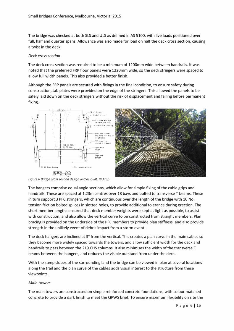
Structural analysis
Detailed structural analysis of the bridge was carried out in OASYS GSA software, which is capable of
non-linear analysis of cable and suspension structures.
Figure 5 Bridge analysis model with udl loading on left half span © Arup
Small Bridges Conference, Melbourne, Victoria, 2015
P a g e 6 | 15
The bridge was checked at both SLS and ULS as defined in AS 5100, with live loads positioned over
full, half and quarter spans. Allowance was also made for load on half the deck cross section, causing
a twist in the deck.
Deck cross section
The deck cross section was required to be a minimum of 1200mm wide between handrails. It was
noted that the preferred FRP floor panels were 1220mm wide, so the deck stringers were spaced to
allow full width panels. This also provided a better finish.
Although the FRP panels are secured with fixings in the final condition, to ensure safety during
construction, tab plates were provided on the edge of the stringers. This allowed the panels to be
safely laid down on the deck stringers without the risk of displacement and falling before permanent
fixing.
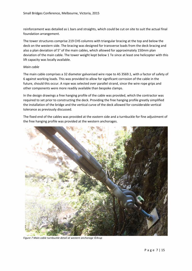
Figure 6 Bridge cross section design and as-built. © Arup
The hangers comprise equal angle sections, which allow for simple fixing of the cable grips and
handrails. These are spaced at 1.23m centres over 18 bays and bolted to transverse T beams. These
in turn support 3 PFC stringers, which are continuous over the length of the bridge with 10 No.
tension friction bolted splices in slotted holes, to provide additional tolerance during erection. The
short member lengths ensured that deck member weights were kept as light as possible, to assist
with construction, and also allow the vertical curve to be constructed from straight members. Plan
bracing is provided on the underside of the PFC members to provide plan stiffness, and also provide
strength in the unlikely event of debris impact from a storm event.
The deck hangers are inclined at 3° from the vertical. This creates a plan curve in the main cables so
they become more widely spaced towards the towers, and allow sufficient width for the deck and
handrails to pass between the 219 CHS columns. It also minimises the width of the transverse T
beams between the hangers, and reduces the visible outstand from under the deck.
With the steep slopes of the surrounding land the bridge can be viewed in plan at several locations
along the trail and the plan curve of the cables adds visual interest to the structure from these
viewpoints.
Main towers
The main towers are constructed on simple reinforced concrete foundations, with colour matched
concrete to provide a dark finish to meet the QPWS brief. To ensure maximum flexibility on site the
Small Bridges Conference, Melbourne, Victoria, 2015
P a g e 7 | 15
reinforcement was detailed as L bars and straights, which could be cut on site to suit the actual final
foundation arrangement.
The tower structures comprise 219 CHS columns with triangular bracing at the top and below the
deck on the western side. The bracing was designed for transverse loads from the deck bracing and
also a plan deviation of 5° of the main cables, which allowed for approximately 150mm plan
deviation of the main cable. The tower weight kept below 1 Te since at least one helicopter with this
lift capacity was locally available.
Main cable
The main cable comprises a 32 diameter galvanised wire rope to AS 3569.1, with a factor of safety of
6 against working loads. This was provided to allow for significant corrosion of the cable in the
future, should this occur. A rope was selected over parallel strand, since the wire rope grips and
other components were more readily available than bespoke clamps.
In the design drawings a free hanging profile of the cable was provided, which the contractor was
required to set prior to constructing the deck. Providing the free hanging profile greatly simplified
the installation of the bridge and the vertical curve of the deck allowed for considerable vertical
tolerance as previously discussed.
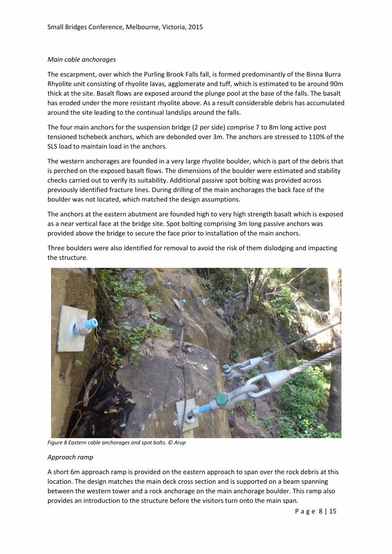
The fixed end of the cables was provided at the eastern side and a turnbuckle for fine adjustment of
the free hanging profile was provided at the western anchorages.
Figure 7 Main cable turnbuckle detail at western anchorage ©Arup
Small Bridges Conference, Melbourne, Victoria, 2015
P a g e 8 | 15
Main cable anchorages
The escarpment, over which the Purling Brook Falls fall, is formed predominantly of the Binna Burra
Rhyolite unit consisting of rhyolite lavas, agglomerate and tuff, which is estimated to be around 90m
thick at the site. Basalt flows are exposed around the plunge pool at the base of the falls. The basalt
has eroded under the more resistant rhyolite above. As a result considerable debris has accumulated
around the site leading to the continual landslips around the falls.
The four main anchors for the suspension bridge (2 per side) comprise 7 to 8m long active post
tensioned Ischebeck anchors, which are debonded over 3m. The anchors are stressed to 110% of the
SLS load to maintain load in the anchors.
The western anchorages are founded in a very large rhyolite boulder, which is part of the debris that
is perched on the exposed basalt flows. The dimensions of the boulder were estimated and stability
checks carried out to verify its suitability. Additional passive spot bolting was provided across
previously identified fracture lines. During drilling of the main anchorages the back face of the
boulder was not located, which matched the design assumptions.
The anchors at the eastern abutment are founded high to very high strength basalt which is exposed
as a near vertical face at the bridge site. Spot bolting comprising 3m long passive anchors was
provided above the bridge to secure the face prior to installation of the main anchors.
Three boulders were also identified for removal to avoid the risk of them dislodging and impacting
the structure.
Figure 8 Eastern cable anchorages and spot bolts. © Arup
Approach ramp
A short 6m approach ramp is provided on the eastern approach to span over the rock debris at this
location. The design matches the main deck cross section and is supported on a beam spanning
between the western tower and a rock anchorage on the main anchorage boulder. This ramp also
provides an introduction to the structure before the visitors turn onto the main span.
Small Bridges Conference, Melbourne, Victoria, 2015
P a g e 9 | 15
BRIDGE CONSTRUCTION
After an open competitive tender DavBridge Construction were awarded the contract to construct
the bridge. A construction sequence was defined on the drawings as follows
1. Prepare bridge site with removal of identified fauna, trees and boulders in agreement with
QPWS.
2. Undertake detailed site survey to identify area of rock to be removed at west tower. Finalize
main span and other key dimensions.
3. Complete removal of identified rock. Extent of rock to be included within west tower
foundations to be agreed with QPWS & designer to minimize volume of concrete.
4. Construct reinforced concrete foundations for west tower and ramp to provide working platform
5. Construct reinforced concrete foundations for east tower to provide working platform
6. Install main cable anchorages and rock bolting.
7. Install main towers on packs to defined profile with temporary support.
8. Install main cables to defined free hanging profile and secure to towers.
9. Install hangers.
10. Install deck stringers and bracing from west to east. Flange splices on stringers to be completed
once all stringers and steelwork is installed.
11. Install western approach ramp to provide working platform.
12. Install GRP deck and handrails.
13. Grout main tower base plates.
After award of contract the contractor elected to install the rock anchorages before the foundation
construction, since this reduced the total number of helicopter flights required.
Following minor vegetation clearance, the detailed survey confirmed the main span as 21.4m
between the tower centrelines and this information was passed to the steelwork fabricator to
commence preparation of the Tekla fabrication model. This was later lengthened to 22.14m to
simplify construction of the eastern tower foundations.
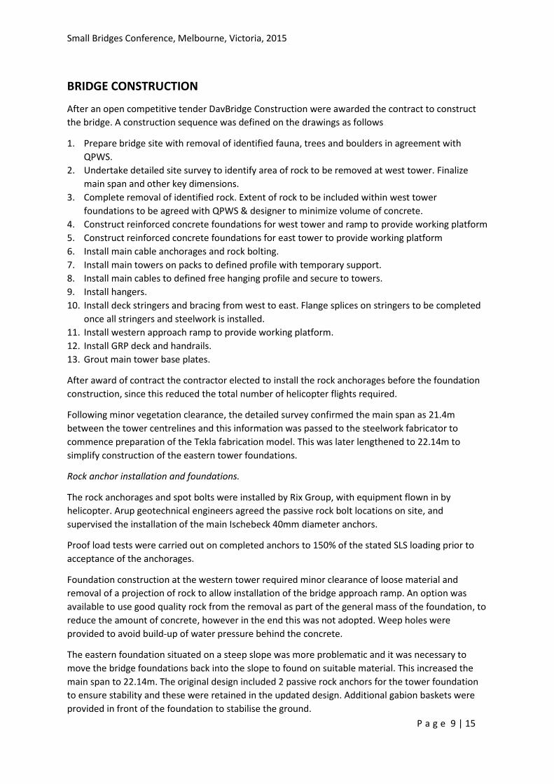
Rock anchor installation and foundations.
The rock anchorages and spot bolts were installed by Rix Group, with equipment flown in by
helicopter. Arup geotechnical engineers agreed the passive rock bolt locations on site, and
supervised the installation of the main Ischebeck 40mm diameter anchors.
Proof load tests were carried out on completed anchors to 150% of the stated SLS loading prior to
acceptance of the anchorages.
Foundation construction at the western tower required minor clearance of loose material and
removal of a projection of rock to allow installation of the bridge approach ramp. An option was
available to use good quality rock from the removal as part of the general mass of the foundation, to
reduce the amount of concrete, however in the end this was not adopted. Weep holes were
provided to avoid build-up of water pressure behind the concrete.
The eastern foundation situated on a steep slope was more problematic and it was necessary to
move the bridge foundations back into the slope to found on suitable material. This increased the
main span to 22.14m. The original design included 2 passive rock anchors for the tower foundation
to ensure stability and these were retained in the updated design. Additional gabion baskets were
provided in front of the foundation to stabilise the ground.
Small Bridges Conference, Melbourne, Victoria, 2015
P a g e 10 | 15
Figure 9 Construction of primary bridge anchors. ©Arup
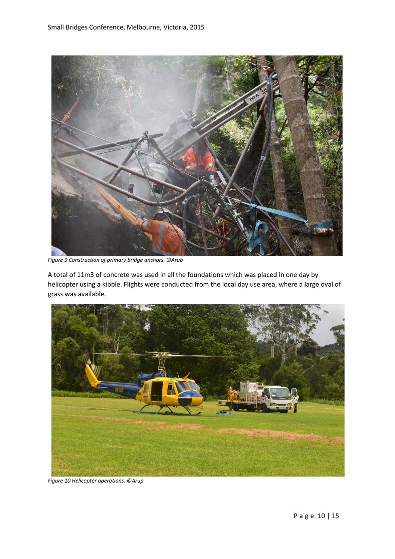
A total of 11m3 of concrete was used in all the foundations which was placed in one day by
helicopter using a kibble. Flights were conducted from the local day use area, where a large oval of
grass was available.
Figure 10 Helicopter operations. ©Arup
Small Bridges Conference, Melbourne, Victoria, 2015
P a g e 11 | 15
Steelwork fabrication and erection
The steelwork was fabricated by Sun Engineering at their Queensland fabrication yard. The largest
component was the western tower with a total weight of 1 Te. During tender discussions it was
agreed that a splice could be provided below deck level if this assisted with construction, however
this was not required.
A Tekla BIM model of the steelwork was prepared by the fabricator and this was reviewed directly
with Tekla Bimsight to ensure an efficient review process. Only minor adjustments were necessary to
the handrail details to simplify construction.
The completed steelwork was galvanised and painted with a black PPG HDG coating system as
specified by QPWS. The handrail was kept as galvanised since it was accepted that the paint would
wear away due to visitor usage. The completed steel was then strapped into suitable lot sizes and
helicoptered into the site.
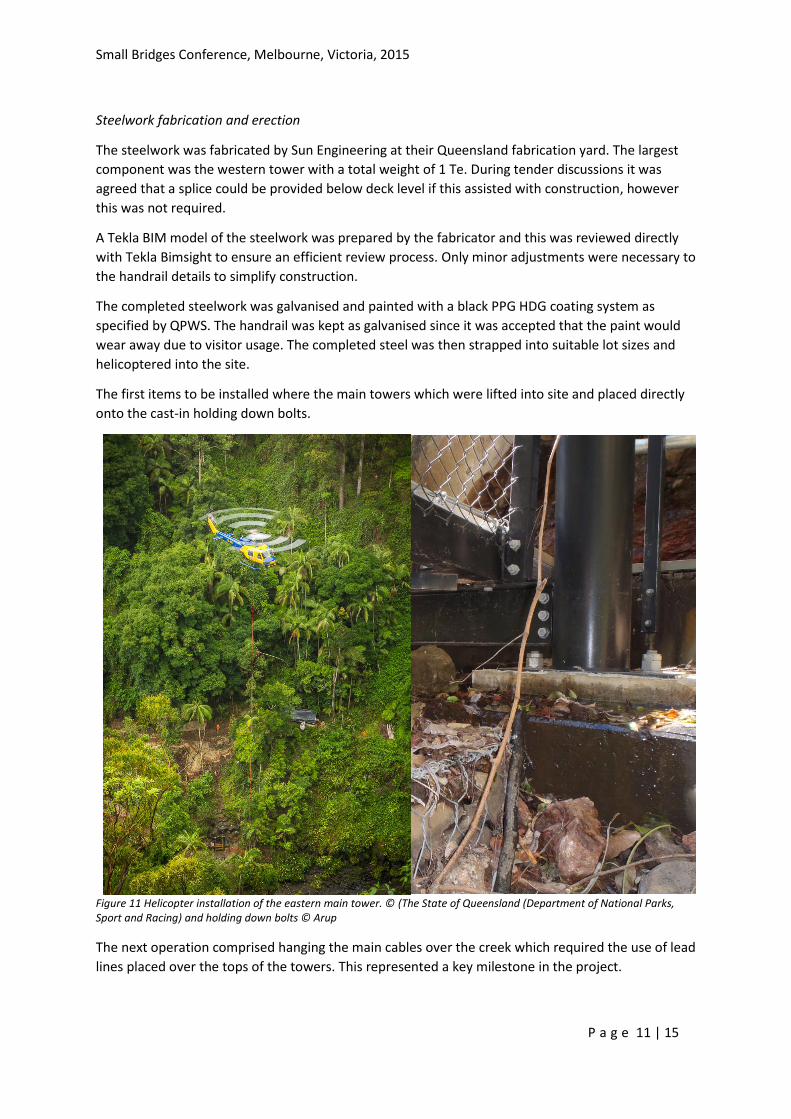
The first items to be installed where the main towers which were lifted into site and placed directly
onto the cast-in holding down bolts.
Figure 11 Helicopter installation of the eastern main tower. © (The State of Queensland (Department of National Parks, Sport and Racing) and holding down bolts © Arup
The next operation comprised hanging the main cables over the creek which required the use of lead
lines placed over the tops of the towers. This represented a key milestone in the project.
Small Bridges Conference, Melbourne, Victoria, 2015
P a g e 12 | 15
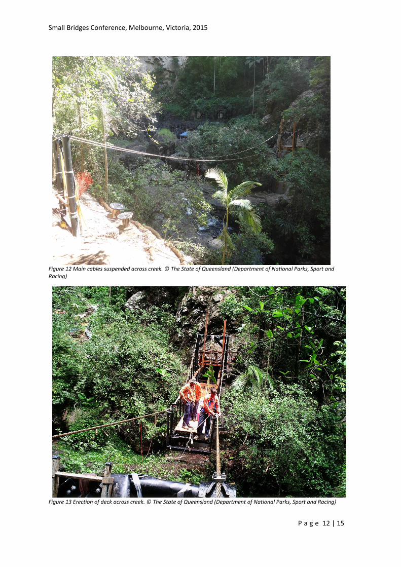
Figure 12 Main cables suspended across creek. © The State of Queensland (Department of National Parks, Sport and Racing)
Figure 13 Erection of deck across creek. © The State of Queensland (Department of National Parks, Sport and Racing)
Small Bridges Conference, Melbourne, Victoria, 2015
P a g e 13 | 15
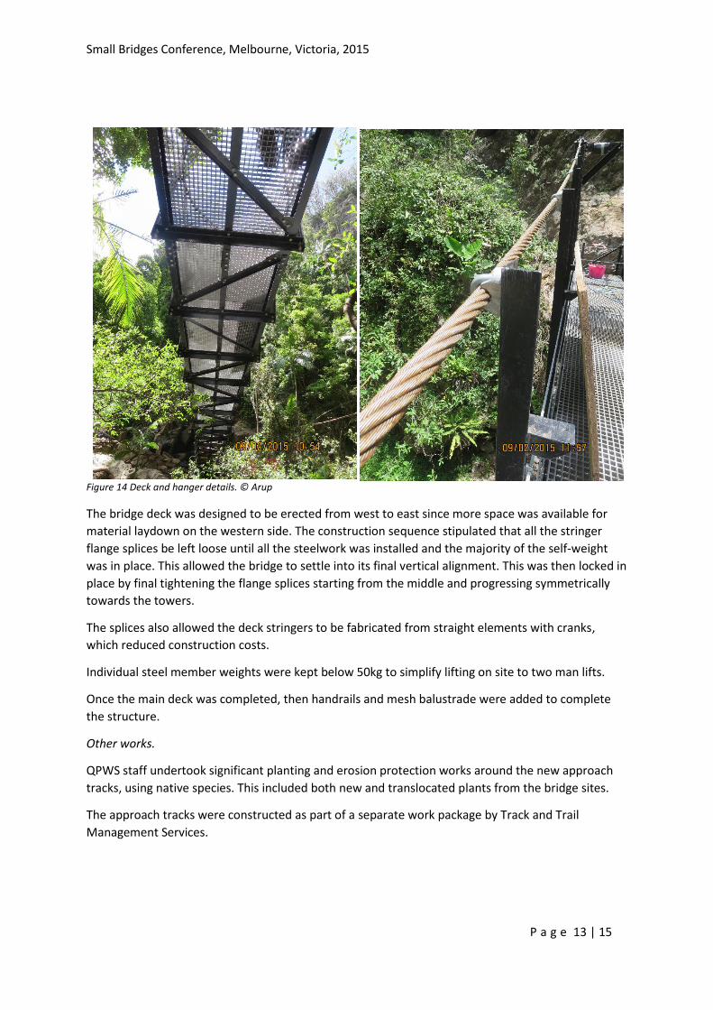
Figure 14 Deck and hanger details. © Arup
The bridge deck was designed to be erected from west to east since more space was available for
material laydown on the western side. The construction sequence stipulated that all the stringer
flange splices be left loose until all the steelwork was installed and the majority of the self-weight
was in place. This allowed the bridge to settle into its final vertical alignment. This was then locked in
place by final tightening the flange splices starting from the middle and progressing symmetrically
towards the towers.
The splices also allowed the deck stringers to be fabricated from straight elements with cranks,
which reduced construction costs.
Individual steel member weights were kept below 50kg to simplify lifting on site to two man lifts.
Once the main deck was completed, then handrails and mesh balustrade were added to complete
the structure.
Other works.
QPWS staff undertook significant planting and erosion protection works around the new approach
tracks, using native species. This included both new and translocated plants from the bridge sites.
The approach tracks were constructed as part of a separate work package by Track and Trail
Management Services.
Small Bridges Conference, Melbourne, Victoria, 2015
P a g e 14 | 15
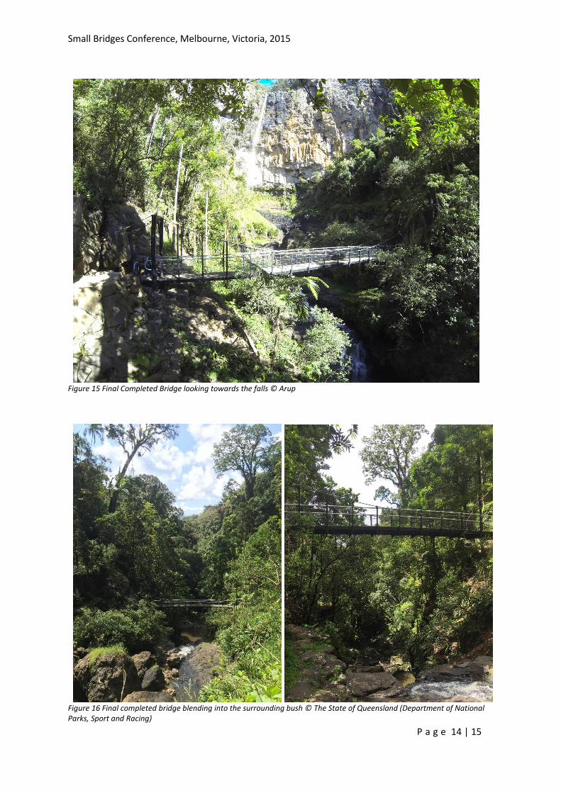
Figure 15 Final Completed Bridge looking towards the falls © Arup
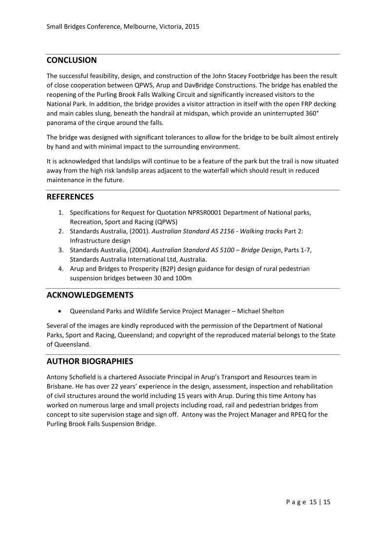
Figure 16 Final completed bridge blending into the surrounding bush © The State of Queensland (Department of National Parks, Sport and Racing)
Small Bridges Conference, Melbourne, Victoria, 2015
P a g e 15 | 15
CONCLUSION
The successful feasibility, design, and construction of the John Stacey Footbridge has been the result
of close cooperation between QPWS, Arup and DavBridge Constructions. The bridge has enabled the
reopening of the Purling Brook Falls Walking Circuit and significantly increased visitors to the
National Park. In addition, the bridge provides a visitor attraction in itself with the open FRP decking
and main cables slung, beneath the handrail at midspan, which provide an uninterrupted 360°
panorama of the cirque around the falls.
The bridge was designed with significant tolerances to allow for the bridge to be built almost entirely
by hand and with minimal impact to the surrounding environment.
It is acknowledged that landslips will continue to be a feature of the park but the trail is now situated
away from the high risk landslip areas adjacent to the waterfall which should result in reduced
maintenance in the future.
REFERENCES
1. Specifications for Request for Quotation NPRSR0001 Department of National parks,
Recreation, Sport and Racing (QPWS)
2. Standards Australia, (2001). Australian Standard AS 2156 - Walking tracks Part 2:
Infrastructure design
3. Standards Australia, (2004). Australian Standard AS 5100 – Bridge Design, Parts 1-7,
Standards Australia International Ltd, Australia.
4. Arup and Bridges to Prosperity (B2P) design guidance for design of rural pedestrian
suspension bridges between 30 and 100m
ACKNOWLEDGEMENTS
Queensland Parks and Wildlife Service Project Manager – Michael Shelton
Several of the images are kindly reproduced with the permission of the Department of National
Parks, Sport and Racing, Queensland; and copyright of the reproduced material belongs to the State
of Queensland.
AUTHOR BIOGRAPHIES
Antony Schofield is a chartered Associate Principal in Arup’s Transport and Resources team in
Brisbane. He has over 22 years’ experience in the design, assessment, inspection and rehabilitation
of civil structures around the world including 15 years with Arup. During this time Antony has
worked on numerous large and small projects including road, rail and pedestrian bridges from
concept to site supervision stage and sign off. Antony was the Project Manager and RPEQ for the
Purling Brook Falls Suspension Bridge.