Embed Size (px)
Citation preview

Volume I Technical description
TREBALL DE FI DE GRAU
“DESIGN AND
CONSTRUCTION OF AN
AUTOMATIC SYSTEM
FOR WATER
MAINTENANCE OF
DOMESTIC POOL”
TFG presentat per obtenir el títol de GRAU en
ENGINYERIA ELECTRÒNICA INDUSTRIAL I
AUTOMÀTICA
Per Joan Ollés Padilla
Barcelona, 11 de Gener de 2016
Director: Sebastian Tornil Sin
Departament de ESAII (707)
Universitat Politècnica de Catalunya (UPC)

Joan Ollés Padilla .
- 1 -
INDEX INDEX ............................................................................................... 1
FIGURES INDEX ................................................................................. 4
TABLES INDEX ................................................................................... 5
EQUATIONS INDEX ............................................................................. 6
RESUM .............................................................................................. 7
RESUMEN .......................................................................................... 7
ABSTRACT ......................................................................................... 7
AKNOWLEDGEMENTS .......................................................................... 8
CHAPTER 1: INTRODUCTION ......................................................... 9
1.1. Description .......................................................................... 9
1.2. Motivation ........................................................................... 11
1.3. Specifications of the system .................................................. 11
1.4. Background and goals .......................................................... 12
CHAPTER 2: SENSORS .................................................................. 13
2.1. Sensor selection .................................................................. 13
2.1.1. Temperature sensor ....................................................... 13
2.1.2. PH meter ....................................................................... 15
2.2. Sensor troubles ................................................................... 18
CHAPTER 3: ELECTRONIC DESIGN ................................................ 19
3.1. Block diagram ..................................................................... 19
3.2. Hardware of the PIC 18F4550 ................................................ 21
3.2.1. Analog-to-Digital ports (ADC) .......................................... 22
3.2.2. Input and Output port (I/O) ............................................. 26
3.2.3. i2c communication ......................................................... 28
3.2.4. Table summary of the used inputs and outputs .................. 34
3.3. RTC .................................................................................... 35
3.4. Multiplexor/Demultiplexor ..................................................... 41
3.5. Motor driver ........................................................................ 44
3.6. Relay ................................................................................. 46
3.7. Electronic circuit .................................................................. 48
3.8. PCB design .......................................................................... 50
3.8.1. PCB layout .................................................................... 50

. Design and construction of an automatic system for water maintenance of a pool
- 2 -
3.8.2. PCB components (BOM) .................................................. 52
CHAPTER 4: MECHANICAL TREATMENT OF LIQUIDS .................... 54
4.1. Peristaltic pump ................................................................... 54
4.1.1. Pump case..................................................................... 57
4.1.2. Rotor ............................................................................ 57
4.1.3. Geared motor ................................................................ 59
4.2. Flexible tube ....................................................................... 60
4.3. Press valve ......................................................................... 61
4.3.1. Geared motor ................................................................ 63
4.4. Mechanical components (BOM) .............................................. 64
CHAPTER 5: SOFTWARE ............................................................... 67
5.1. Main program ...................................................................... 67
5.2. RTC and i2c communication .................................................. 71
5.3. pH and temperature signal .................................................... 74
5.4. Motors, endstops and multiplexor control ................................ 77
CHAPTER 6: SIMULATION ............................................................ 83
6.1. Circuit simulation ................................................................. 83
CHAPTER 7: SET UP OF THE HARDWARE ...................................... 86
7.1. Enclose of the mechanics parts .............................................. 88
7.2. Enclosure of the electronics ................................................... 89
7.3. Connexions of the system ..................................................... 91
7.3.1. Electric circuit ................................................................ 91
7.3.2. Pipes connexion ............................................................. 93
CHAPTER 8: NORMATIVES AND LEGISLATION .............................. 95
CHAPTER 9: PLANNING OF THE WORK ......................................... 99
CHAPTER 10: CONCLUSIONS ........................................................ 100
CHAPTER 11: BIBLIOGRAPHY ...................................................... 103
11.1. Bibliographic References ..................................................... 103
11.2. Bibliography for consultation ............................................... 104
ANNEX 1 SOURCE CODE ............................................................... 105
12.1. Main program, firm v9.4 ..................................................... 105
12.2. ini_ports_variables ............................................................. 112
12.3. Function, getpH ................................................................. 114
12.4. Function, getT ................................................................... 116

Joan Ollés Padilla .
- 3 -
12.5. Function, getTime .............................................................. 118
12.6. Function, pHacid ................................................................ 122
12.7. Function, pHbasic .............................................................. 123
12.8. Function, pumpLiquid ......................................................... 124
12.9. Function, closevalves ......................................................... 126
12.10. Function, openvalves ....................................................... 130
12.11. Function, pumping .......................................................... 135
ANNEX 2 MAINTAINING POOL WATER ......................................... 137
13.1. Filter system ..................................................................... 137
13.1.1. Filter options ............................................................... 137
13.2. pH levels .......................................................................... 138
13.2.1. Measuring pH .............................................................. 138
13.3. Chlorine ............................................................................ 139
13.3.1. Chlorine levels ............................................................. 140
13.3.2. Chlorine options ........................................................... 140
13.4. Algaecide .......................................................................... 141
ANNEX 3 pH LEVEL CORRECTION .................................................. 142
14.1. Acid current pH level .......................................................... 143
14.2. Basic current pH level ......................................................... 145

. Design and construction of an automatic system for water maintenance of a pool
- 4 -
FIGURES INDEX
All referred figures have their source and, if not, it means that the author
has created the figure.
Figure 1 Block diagram of the system ........................................................................................................ 10
Figure 2 Waterproof case LM35 ................................................................................................................. 14
Figure 3 Pin out, basic centigrade temperature sensor - Source: Datasheet LM35 ................................... 15
Figure 4 Accuracy vs Temperature - Source: Datasheet LM35 ................................................................... 15
Figure 5 PH meter + driver connection - Source: DFrobot.com .................................................................. 16
Figure 6 pH driver schematic - Source: DFrobot.com ................................................................................. 16
Figure 7 pH driver schematic described...................................................................................................... 17
Figure 8 Complete block diagram of the system ........................................................................................ 20
Figure 9 Pin diagram PIC 18F4550 - Source: engineersgarage.com .......................................................... 21
Figure 10 Model analog input converter - Source: Datasheet PIC18f4550 ................................................ 23
Figure 11 A/D block diagram - Source: Datasheet PIC18f4550 .................................................................. 24
Figure 12 Generic I/O port operation - Source: Datasheet PIC 18f4550 ..................................................... 27
Figure 13 MSSSP block diagram for i2c mode - Source: Datasheet PIC 18f4550 ....................................... 29
Figure 14 Operational circuit for RTC DS 3221 - Source: Datasheet DS3231.............................................. 36
Figure 15 DS3231 schematic described ...................................................................................................... 37
Figure 16 Start bit for the communication i2c ............................................................................................ 38
Figure 17 Transferring data between RTC and the PIC .............................................................................. 39
Figure 18 Functional diagram HEF4051 - Source: Datasheet HEF4051 ...................................................... 41
Figure 19 HEF4051 chip description ........................................................................................................... 43
Figure 20 Operating area of the HEF4051 for the system - Source: Datasheet HEF4051 .......................... 44
Figure 21 Diagram of the motor driver ...................................................................................................... 45
Figure 22 Internal schematics of and H bridge motor control - Source: robotid.com ................................ 46
Figure 23 Schematic relay module ............................................................................................................. 47
Figure 24 Schematic explanation ............................................................................................................... 47
Figure 25 Optocoupler diagram - Source: electronics-lab.com .................................................................. 48
Figure 26 Electronics circuits scheme ......................................................................................................... 49
Figure 27 PCB layout, all the component placed ........................................................................................ 51
Figure 28 PCB layout, routed of all the components .................................................................................. 51
Figure 29 The peristaltic pump ................................................................................................................... 55
Figure 30 Scheme of operation of a peristaltic pump - Source: Verderflex.com ........................................ 55
Figure 31 Exploded view of peristaltic pump .............................................................................................. 56
Figure 32 CAD Top part pump .................................................................................................................... 57
Figure 33 CAD Bottom part pump .............................................................................................................. 57
Figure 34 Rear view CAD rotor assembled ................................................................................................. 58
Figure 35 Front view CAD rotor assembled ................................................................................................ 58
Figure 36 Exploded view rotor .................................................................................................................... 58
Figure 37 Rear view peristaltic pump, motor and gears ............................................................................ 59
Figure 38 Exploded view gears and geared motor ..................................................................................... 60
Figure 39 Picture of the tube Hypalom-CSM from VerderFlex to be used in this system - Source:
verderflex.com ............................................................................................................................................ 61
Figure 40 The press valve ........................................................................................................................... 62
Figure 41 CAD press valve, fully close ......................................................................................................... 62
Figure 42 Exploded view press valve .......................................................................................................... 63
Figure 43 Exploded view geared motor press valve ................................................................................... 64
Figure 44 First run wizard flowchart .......................................................................................................... 68

Joan Ollés Padilla .
- 5 -
Figure 45 Control menu displaying the insert data of water volume ......................................................... 69
Figure 46 Control menu displaying the insert data of chemical concentration .......................................... 69
Figure 47 Main program loop flowchart .................................................................................................... 70
Figure 48 Flowchart to filter the sample from sensor ................................................................................ 76
Figure 49 Control menu displaying the current time, temperature and pH ............................................... 77
Figure 50 Flowchart to add chemical to the pool ....................................................................................... 79
Figure 51 control menu displaying the current operation to correct pH .................................................... 82
Figure 52 Scheme of all the system for simulation ..................................................................................... 84
Figure 53 Animation of the motor in the simulation .................................................................................. 85
Figure 54 Animation of the LED in the simulation ...................................................................................... 85
Figure 55 The complete system .................................................................................................................. 87
Figure 56 CAD enclosure mechanical parts ................................................................................................ 88
Figure 57 CAD enclosure electronics components ...................................................................................... 89
Figure 58 the electronics cover ................................................................................................................... 90
Figure 59 Electric scheme of the system .................................................................................................... 92
Figure 60 Pipes scheme of the system ........................................................................................................ 93
Figure 61 T connector for the pipes - Source: RS Componentes ................................................................. 94
Figure 62 Risk of finger get tramped - Source: Aenor.es ............................................................................ 96
Figure 63 Ferrite for the electromagnetic compatibility - Source: RScomponentes ................................... 96
Figure 64 Example of insulation of the crystal oscillator ............................................................................ 97
Figure 65 Gantt diagram of this project ..................................................................................................... 99
Figure 66 System fully assembled ............................................................................................................ 101
Figure 67 Actual human interface of the system...................................................................................... 102
TABLES INDEX
Table 1 General specifications of the system ............................................................................................. 11
Table 2 Specs and features of PIC18f4550 ................................................................................................. 22
Table 3 ADCON0 register bits that control the ADC ................................................................................... 24
Table 4 ADCON1 register bits that control the ADC ................................................................................... 25
Table 5 ADCON2 register bits that control the ADC ................................................................................... 25
Table 6 SSPSTAT, i2c register ...................................................................................................................... 30
Table 7 SSPCON1, i2c register .................................................................................................................... 31
Table 8 SSPCON2, i2c register .................................................................................................................... 33
Table 9 General pins PIC 18f4550 ............................................................................................................... 34
Table 10 PortA pins PIC 18f4550 ................................................................................................................ 34
Table 11 PortB pins PIC 18f4550 ................................................................................................................ 34
Table 12 Port C pins PIC 18f4550................................................................................................................ 35
Table 13 Port D pins PIC 18f4550 ............................................................................................................... 35
Table 14 Port E pins PIC 18f4550 ................................................................................................................ 35
Table 15 Specs and features of DS3231 ..................................................................................................... 36
Table 16 Address map of the DS3231 - Source: Datasheet DS3231 .......................................................... 39
Table 17 Specs and features of HEF4051 ................................................................................................... 42
Table 18 Pin description and connexion HEF4051 ...................................................................................... 43
Table 19 Specs and features L293D ............................................................................................................ 45
Table 20 Build of materials PCB components ............................................................................................. 53

. Design and construction of an automatic system for water maintenance of a pool
- 6 -
Table 21 Specification for the correct peristaltic tube ................................................................................ 61
Table 22 BOM commercial and 3D printed parts ....................................................................................... 66
Table 23 BOM screws ................................................................................................................................. 66
Table 25 Main program, infinite loop......................................................................................................... 69
Table 26 Main conditionals to trigger the system ...................................................................................... 71
Table 27 Definition of i2c registers ............................................................................................................. 71
Table 28 Definition i2c address .................................................................................................................. 72
Table 29 Bits switcher to obtain data from RTC ......................................................................................... 72
Table 30 Write and read from the slave RTC .............................................................................................. 73
Table 31 Scrip to record data from RTC and shown on the LCD ................................................................. 74
Table 32 Scrip to obtain sample from analog inputs .................................................................................. 75
Table 34 Scrip to convert liquid volume to turn for the pump .................................................................... 77
Table 36 Scrip to operate a motor of a press valve .................................................................................... 80
Table 37 Scrip to calculate the number of turn of the pump ...................................................................... 81
Table 38 Pool pH level chart ..................................................................................................................... 142
Table 39 Needed pool parameter to correct the pH level ........................................................................ 143
EQUATIONS INDEX
Equations 1 Actual value of the calibration potentiometer ....................................................................... 17
Equations 2 Gain of the low pass filter stage ............................................................................................. 18
Equations 3 Gain of the inverter stage ....................................................................................................... 18
Equations 4 Rpu max value ........................................................................................................................ 38
Equations 5 Rpu min value ......................................................................................................................... 38
Equations 6 Transform from BCD value to binary ...................................................................................... 40
Equations 7 Transform from binary value to BCD ...................................................................................... 40
Equations 8 Gear ratio of the peristaltic pump .......................................................................................... 59
Equations 9 angular speed of the peristaltic pump .................................................................................... 60
Equations 10 Gear ratio of the press valve ................................................................................................ 63
Equations 11 angular speed of the press valve .......................................................................................... 64
Equations 12 Group of equations to calculate the pH correction for acid case ....................................... 145
Equations 13 Group of equations to calculate the pH correction for base case ...................................... 146

Joan Ollés Padilla .
- 7 -
RESUM
Aquest treball de final de grau consisteix en el disseny i construcció d'un
sistema automàtic de dosificació dels productes químics necessaris pel
manteniment i correcció del pH de l'aigua d'una piscina domèstica.
El sistema està controlat per un microcontrolador PIC el qual amb la
informació recollida pel sensors de pH i temperatura i previ càlcul del
programari, acciona la corresponent vàlvula del producte necessari. Després
acciona la bomba peristàltica, enviant el producte al sistema de filtració
estàndard de la piscina.
El microcontrolador també tindria control de la bomba centrifuga del
sistema de filtració de la piscina per garantir que el producte químic es
distribueixi per la piscina.
RESUMEN
Este trabajo de final de grado consiste en el diseño y construcción de un
sistema automático de dosificación de los productos químicos necesarios
para el mantenimiento y corrección del pH del agua de una piscina
doméstica.
El sistema está controlado por un microcontrolador PIC el cual con la
información recogida por el sensores de pH y temperatura y previo cálculo
del software, accionara la correspondiente válvula del producto necesario.
Después accionaría la bomba peristáltica, enviando el producto al sistema
de filtración estándar de la piscina.
El microcontrolador también tendría control de la bomba centrifuga del
sistema de filtración de la piscina para garantizar que el producto químico
se distribuya por la piscina.
ABSTRACT
This final degree work involves the design and construction of an automatic
dosing of chemicals required for maintenance and correction of pH water of
a domestic swimming pool.

. Design and construction of an automatic system for water maintenance of a pool
- 8 -
The system is controlled by a microcontroller PIC which with the information
collected from the pH and temperature sensors and pre-calculation of the
software, trigger the corresponding valve of the required product. After
would also trigger the peristaltic pump, sending the product to the standard
filtration system of the pool.
The microcontroller also would control the centrifugal pump filtration system
from the pool to ensure that the chemical is distributed in the pool.
AKNOWLEDGEMENTS
To my family, friends and colleagues who have supported me during the
project development. Especially to Eduardo for help me with the
communication, Raquel for her help with chemistry of the pH correction and
to my work colleges from BCN3Dtechnologies Fundacio CIM for inspiring
with the mechanical knowledge
Finally I would like to thank to the faculty for four years of EUETIB degree
and to my professor Sebastian Tornill for helping me to make this project
real.

Joan Ollés Padilla .
- 9 -
CHAPTER 1:
INTRODUCTION
1.1. Description
System for automatic dosing of chemicals needed for pH correction and
maintenance of a domestic pool.
The system is controlled by a PIC microcontroller which actuates the valves
of the tanks of chemicals according to the program, opening only the valve
corresponding to the required product and then operate the pump, sending
the product to the standard filtering system of the pool.
The microcontroller also will take control of the pump of the filtration
system to ensure that the chemical is distributed evenly in the pool.
The system has a pH sensor, which includes a pH probe and a driver signal
for amplification and filtering. Once a week, the sensor sends the current
value of pH to the microcontroller, using mathematical algorithms calculate
the amount of acid or base needed to adjust the pool to 7.4 pH.
To make the calculation, the microcontroller know the water temperature
(using an analogue temperature sensor) and ask to the user during the first
run about the total amount of water and the concentration of acid or base
storage in the chemical deposits.

. Design and construction of an automatic system for water maintenance of a pool
- 10 -
Also the system daily adds a fix amount of chlorine based on the water
volume that the user specified on the system.
The software loaded in this microcontroller is responsible of:
Weekly pH control and temperature.
Weekly pH correction, if necessary.
Daily scheduled to add the amount of fixed liquid chlorine (routine
maintenance).
The system can be split into the following parts:
Peristaltic pump, for dosing.
Press valves.
pH sensor.
Temperature Sensor.
PIC microcontroller.
Relay, to trigger the external water pump.
Figure 1 Block diagram of the system

Joan Ollés Padilla .
- 11 -
The whole system is composed of a flexible tube. This peristaltic pump and
the strangler valve are based on deforming the tube to block the flow of
liquid or push it.
1.2. Motivation
All the people how have a garden with a swimming pool in his backyard
know that you have to spend many time working on it to keep it nice and
clean. Is an arduous task. My motivation is to make the most monotonous
task automatic for the user. The idea is to take control of the related tasks
for the maintenances of the water pool.
1.3. Specifications of the system
Below are the summary table with the general characteristics of the system:
Magnitudes Max value Min value Resolution Units
Temperature 40 5 0.1 ºC
pH 14 1 0.1 pH
Time 7-12:59:59 1-00:00:00 1-01:01:01 *DoW-hh:mm:ss
Input voltage
230 AC 115 AC - V
Power
consumption standby
3 2 0.1 W
Power consumption
fully
operative
4 2 0.1 W
Pool water
volume
40000 500 500 L
Power consumption
external pump
3680 1 - W
*DoW = Day of the week
Table 1 General specifications of the system

. Design and construction of an automatic system for water maintenance of a pool
- 12 -
1.4. Background and goals
Nowadays an owner of a swimming pool can find some similar systems to
keep the water clean, but the unique one, which can do the maintenances
of all the aspects of the water, is a salt chloride system.
The salt chloride system is based on salty water pool without chlorine. The
system has diversions electrodes which using direct current performs a
chemical reaction with the dissolved salt in the water. At the end the user
doesn't have to add any chlorine or algaecide because this chemical
reaction produce all the necessary products. Also the salt chloride system
has and independent system to regulated the pH.
The disadvantage of this system is that is really expensive compared to the
price of a small pool (less than 40.000 liters). The electrodes of this kind of
system are made of titanium, gold or platinum. So at the end if you own a
small swimming pool the unique way to maintain the water fully automatic
is to spend the same amount of money that you spend on the construction
of the pool, in the salt chloride system.
The goal is to make a cheap and easy system for these users with can't
afford a salt chloride system. These are the followed step to achieve this
goal:
1. Design of the electronic hardware.
2. Control Software.
3. Simulation of the system.
4. Construction of the prototype.
5. Set up of the system.

Joan Ollés Padilla .
- 13 -
CHAPTER 2:
SENSORS
2.1. Sensor selection
The system needs some data from the measuring devices to begin with the
different process. Is necessary to have some kind of interface to transform
a physic magnitude to and electrical signal to be interpreted by the
microcontroller.
These sensors generally use to be analogue voltage levels and provide
proportional to the magnitude or intensity that measure, although there are
also varying electrical properties such as conductivity or the ability and
need to convert these stages of adaptation variations in intensity or voltage
signals.
For every magnitude measuring station is necessary to have a sensor that
specializes in measuring this magnitude. The sensors that are used in the
system are explained in this chapter.
2.1.1. Temperature sensor
There are multitudes of sensors that measure temperature, but should
always consider what is the purpose of the measure, and from there select

. Design and construction of an automatic system for water maintenance of a pool
- 14 -
the most suitable. Is not the same, measure the temperature of an
industrial process rather than the body temperature of man, because in the
second case requires a remarkable accuracy compared to the first case.
The resistive sensors like PT-100 or thermocouples can be used to measure
temperature, but there are other more reliable, for example, which are
based on semiconductors. This semiconductors sensor also provides a
digital output for the data.
The system operates with a LM-35 a lineal temperature sensor mounted in
waterproof metal case.
There are several reasons to choose this sensor:
Low cost, in this system we are looking for the minim cost of the
equipment with losing so much precision.
Linea sensor, the signal that you get from the sensor is a linear
proportional, much easy to operated with
Low power consumption and interference, the low current
consumption (60μA) allows you to be more precise to obtain the final
measure
High precision between 0.5 °C to 50 °C, between this range of
temperatures the sensor is particular more precise that normal
(±0.5°C). Fortunately the water pool during the summer season used
to be inside this temperature range.
Therefore this sensor is give the temperature with less accurately than
other temperature sensor but in this system is not necessary to have a
highly precision sensor. Because we only use the temperature value to
slightly correct de pH value.
Figure 2 Waterproof case
LM35

Joan Ollés Padilla .
- 15 -
2.1.2. PH meter
This device measure potentiometrically the pH, which is either the
concentration or the activity of hydrogen ions, of an aqueous solution. It
has a glass electrode and a reference electrode build in.
When the user submerge the probe in to a liquid solution the, electrons flow
from the electrode to the reference electrode or vice versa. This electric
current is converted to positive voltage, filtered and amplified by the pH
sensor driver and send it to the microcontroller.
Figure 3 Pin out, basic
centigrade temperature sensor
- Source: Datasheet LM35
Figure 4 Accuracy vs Temperature -
Source: Datasheet LM35

. Design and construction of an automatic system for water maintenance of a pool
- 16 -
This driver is specifically designed from the manufacture of the pH prove, to
ensure that the microcontroller receive a stable and accurate signal. This
driver also has an adjustment potentiometer to slightly correct the pH
signal. The user is able to calibrate the pH meter by submerging the prove
in to a well calibrated solution and adjusting this potentiometer.
The Figure 9 is the diagram for the pH driver. The probe signal enters IC1
via an RC circuit designed to allow only relatively slow signal variations (and
avoid getting parasite HF signals). IC1 is a CMOS op-amp and thus has very
high impedance. The gain of IC1 is adjusted with the potentiometer P1. C2
is there for the amplifier stability.
Once the signal has been amplified it enters an offset circuit built around
IC2. IC2 is a more classic TL081 op-amp commonly found in audio devices,
among others. The offset is defined by two potentiometers R9, this allows
the range swept by P2 to be symmetric. The circuit is designed to provide
an average offset of 2V. This step is necessary to eliminate de negative
voltage of the signal because the analogue input of the microcontroller is
not capable to measure it.
The voltages for the signal evolve in the circuit as follows:
Figure 5 PH meter + driver
connection - Source: DFrobot.com
Figure 6 pH driver schematic - Source: DFrobot.com

Joan Ollés Padilla .
- 17 -
Before IC1, input voltage: -0.414/+0.414V (this might depend on the
electrode used and its age)
After IC1, the low pass filter: -2/+2V
After IC2, the inverter OPAMP: 0/+4V
Output voltage, on the microcontroller: 0.00 - 14.00 pH
In the stage of the low pass filter the gain change according to a
potentiometer on the board.
The value of the R5 depends on the actual value that the user set on the
potentiometer. The full resistance of the resistor R5 is equal to 4,7KΩ
Equations 1 Actual value of the calibration potentiometer
Figure 7 pH driver schematic described

. Design and construction of an automatic system for water maintenance of a pool
- 18 -
In case of a good calibration the actual value of R5 is around 4,1KΩ, so the
gain of the low pass filter will be like so:
Equations 2 Gain of the low pass filter stage
For the next stage, the inverter, the gain is fixe to the next valve:
Equations 3 Gain of the inverter stage
As the equation 3 shows, the gain don't amplify the signal it just invert the
output in order to convert the negative voltage to positive voltage
2.2. Sensor troubles
The chosen pH sensor for this system is not the best choice, because it
cannot stay for long periods of time under water, it may rest in the storage
solution. But it was more costly and complicated to use the suitable sensor
form this purpose.
The software of the system adds a fixed amount of chloride based on the
amount of water that the user specified on the menu. Exist some chloride
sensor on the market but they are really expensive and extremely delicate,
can’t be installed outside. For that reason no chloride sensor have been
used in this system.

Joan Ollés Padilla .
- 19 -
CHAPTER 3:
ELECTRONIC
DESIGN
The electronics design go from with components are necessary to the finally
position to be mounted. Also is really important how to configuration those
devices using the software inside the microcontrollers. In this chapter are
explained all the step to design the main board of the system
3.1. Block diagram
In the block diagram of the system, blocks connected by arrows that show
the relationships between them represent the principal parts or functions.

. Design and construction of an automatic system for water maintenance of a pool
- 20 -
There are two main parts, the one on the left side with describe the
hardware of the actual system of this project. On the right side is the
hardware expect from the user who install this system.
The bloc diagram is build it with arrow, the wider one represent liquid pipes,
and the thin ones, electrical connections. If the arrow have two triangles at
both ends represent a bidirectional connection.
Figure 8 Complete block diagram of the system

Joan Ollés Padilla .
- 21 -
3.2. Hardware of the PIC 18F4550
The PIC18F4550 is the main body of the system. It is a of the popular PIC
microcontroller Microchip Technology, characterized for easy programming
and performance combined with a high ratio quality - price really attractive.
PIC18F4550 is an 8-bit microcontroller of PIC18 family. PIC18F family is
based on 16-bit instruction set architecture. PIC18F4550 consists of 32 KB
flash memory, 2 KB SRAM and 256 Bytes EEPROM.
This is a 40-pin PIC microcontroller consisting of 5 I/O ports (PORTA,
PORTB, PORTC, PORTD and PORTE). PORTB and PORTD have 8 pins to
receive/transmit 8-bit I/O data. The remaining ports have different numbers
of pins for I/O data communications.
PIC18F4550 can work on different internal and external clock sources. It
can work on a varied range of frequency from 31 KHz to 48 MHz.
PIC18F4550 has four in-built timers. For this system and for the program
that we will run inside the microcontroller the frequencies will be 4MHz.
There are various inbuilt peripherals like ADC, comparators etc. in this
controller.
Figure 9 Pin diagram PIC 18F4550 - Source:
engineersgarage.com

. Design and construction of an automatic system for water maintenance of a pool
- 22 -
PIC18F4550 is an advanced microcontroller, which is equipped with
enhanced communication protocols like EUSART, SPI, I2C, USB etc.
Features PIC18F4550
Operating Frequency DC – 48 MHz Program Memory (Bytes) 32768
Program Memory (Instructions)
16384
Data Memory (Bytes) 2048
Data EEPROM Memory (Bytes)
256
Interrupt Sources 20 I/O Ports Ports A, B, C, D, E Timers 4
Capture/Compare/PWM Modules
1
Enhanced Capture/ Compare/PWM Modules
1
Serial Communications MSSP, Enhanced USART Universal Serial Bus (USB) Module
1
Streaming Parallel Port (SPP)
Yes
Analog-to-Digital Module 13 Input Channels, 10-bit Comparators 2 Resets (and Delays) POR, BOR, RESET Instruction,
Stack Full, Stack Underflow (PWRT, OST), MCLR (optional),
WDT Programmable Low-Voltage Detect
Yes
Programmable Brown-out Reset
Yes
Instruction Set 75 Instructions; 83 with Extended Instruction Set
enabled Packages 40-pin PDIP
44-pin QFN 44-pin TQFP
Table 2 Specs and features of PIC18f4550
3.2.1. Analog-to-Digital ports (ADC)
Joan Ollés Padilla .
- 23 -
One of the most important benefits of this microcontroller is that converts
digital values into analogue measurements with a 10 bits resolution.
It is a successive approximation converter with four multiplexed analogue
channels that are part of the Port A. The input voltage Vref reference limits
the maximum voltage conversion. The provision of these channels is not
fixed and can be adjusted to suit the user by modifying a register as
discussed below.
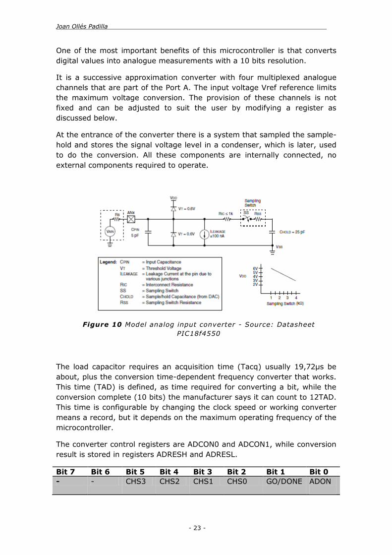
At the entrance of the converter there is a system that sampled the sample-
hold and stores the signal voltage level in a condenser, which is later, used
to do the conversion. All these components are internally connected, no
external components required to operate.
The load capacitor requires an acquisition time (Tacq) usually 19,72μs be
about, plus the conversion time-dependent frequency converter that works.
This time (TAD) is defined, as time required for converting a bit, while the
conversion complete (10 bits) the manufacturer says it can count to 12TAD.
This time is configurable by changing the clock speed or working converter
means a record, but it depends on the maximum operating frequency of the
microcontroller.
The converter control registers are ADCON0 and ADCON1, while conversion
result is stored in registers ADRESH and ADRESL.
Bit 7 Bit 6 Bit 5 Bit 4 Bit 3 Bit 2 Bit 1 Bit 0
- - CHS3 CHS2 CHS1 CHS0 GO/DONE ADON
Figure 10 Model analog input converter - Source: Datasheet
PIC18f4550

. Design and construction of an automatic system for water maintenance of a pool
- 24 -
Table 3 ADCON0 register bits that control the ADC
Description of the register bits:
CHS3 to CHS0: Bits selection of analog inputs: with "000" is selects
AN0 input until "100" is selected AN4 entry.
GO / DONE: Ability converter, placing this bit to '1' initialize the
system conversion, and returns a "0" once the conversion is
complete.
ADON: Bit Enabling the converter:
'0': The converter remains offline and does not consume
anything.
1 ': The converter is enabled.
Figure 11 A/D block diagram - Source: Datasheet
PIC18f4550

Joan Ollés Padilla .
- 25 -
Bit 7 Bit 6 Bit 5 Bit 4 Bit 3 Bit 2 Bit 1 Bit 0
- - VCFG 0 VCFG 0 PCFG 3 PCFG20 PCFG1 PCFG0
Table 4 ADCON1 register bits that control the ADC
Description of the register bits:
VCFG0: Voltage Reference Configuration bit (VREF- source)
1 = VREF- (AN2)
0 = VSS
VCFG0: Voltage Reference Configuration bit (VREF+ source)
1 = VREF+ (AN3)
0 = VDD
PCFG3:PCFG0: A/D Port Configuration Control bits:
1101 = Digital I/O from AN12 to AN2
Analog input to AN1 and AN0
Bit 7 Bit 6 Bit 5 Bit 4 Bit 3 Bit 2 Bit 1 Bit 0
ADFM - ACQT2 ACQT1 ACQT0 ADCS2 ADCS1 ADCS0
Table 5 ADCON2 register bits that control the ADC
Description of the register bits:
ADFM: A/D Result Format Select bit
1 = Right justified
0 = Left justified
ACQT2:ACQT0: A/D Acquisition Time Select bits
111 = 20 TAD
110 = 16 TAD
101 = 12 TAD
100 = 8 TAD
011 = 6 TAD
010 = 4 TAD

. Design and construction of an automatic system for water maintenance of a pool
- 26 -
001 = 2 TAD
000 = 0 TAD
ADCS2:ADCS0: A/D Conversion Clock Select bits
111 = FRC (clock derived from A/D RC oscillator)
110 = FOSC/64
101 = FOSC/16
100 = FOSC/4
011 = FRC (clock derived from A/D RC oscillator)
010 = FOSC/32
001 = FOSC/8
000 = FOSC/2
In order to do the conversion properly, these steps must be follow as
described below:
1. Configure entries in Port bits and justification through ADCON1.
2. Select one of the entrances to the Port through ADCON0.
3. Select the clock frequency of the converter through ADCS1 and
ADCS0 registry ADCON0.
4. Enable the converter putting noticed ADCON0 bit to '1'.
5. Initiate the conversion putting the bit GO / DONE ADCON0 of a
'one'.
6. Wait time conversion until GO / DONE back to '0'.
7. Make reading records that contain the ADRESL and ADRESH
conversion.
In the program the converter station is configured so that the working
frequency is FOSC / 2 bits of justification is on the right, leaving the first
eight bits of less weight in the register ADRESL and the two last more
weight ADRESH and entries Port A (AN0 to AN1) are configured as analog.
In the system we don't need any voltage reference to extend the accuracy
of the ADC.
3.2.2. Input and Output port (I/O)
Input and Output ports are used for the microcontroller to communicate
with the outside. These ports include the digital inputs and outputs, but in

Joan Ollés Padilla .
- 27 -
the case of the PIC is also has multiplexed inputs and outputs with other
special features like entries analog data entries interruptions entries,
programming divers, etc. That is why each port topology changes
substantially having these extra features are all up and each pin port has its
special configuration.
The PIC18F4550 has five ports A, B, C, D and E. The ports A to D are 8 bits
while the E port is just 4 bits. All ports work equally and are associated with
a control register that sets of if they were reading or write. The first register
and placing TRISX bits called a '1' or '0' pin port associated this bit becomes
read or write, so that within a port can having inputs and outputs
simultaneously. The second is called PORTX and is to write or read the
contents of the port via this record.
However each port has its particularity and is known for its architecture
master its operation and its special features.
Port A is an 8-bit port is controlled from the registers TRISA and PORTA.
Putting a "0" bits of the TRISA pin becomes associated with writing, while if
set to "1", the pin is read.
Figure 12 Generic I/O port operation -
Source: Datasheet PIC 18f4550

. Design and construction of an automatic system for water maintenance of a pool
- 28 -
The architecture of the pins RA2 to RA5 is the same. It has an output a
stage push-pull MOSFET's formed by two P-type and N, which makes the
stage can give zeros and ones and either put in high mode impedance
should be in reading mode. These pins are also multiplexed analog inputs of
the ADC converter and must be taken into mind as to operate as digital
inputs must configure the registry ADCON1 properly.
The pin RA6 / OSC2 is different from the other pins, this pin is primarily
used to connect and input clock signal as and oscillator for the
microcontroller. In order to use this port the user must activate ECIO,
ECPIO and INTIO mode and use the internal oscillator.
Port B is an 8-bit port that works like other ports in TRISB through records
and PORTB. This port, part has multiplexed pins divers communication I2C
and SMBus, which makes the architecture is more complex than other
ports. On the other hand, each pin has a push-pull output stage formed by
MOSFET's, can therefore to '0', '1' or put pins in high impedance in the case
of reading.
Port C is an 8-bit port that works like other ports in TRISC through records
and PORTC. This port has multiplexed pins divers for USB serial
communication. On the other hand, each pin has a push-pull output stage
formed by MOSFET's, can therefore to '0', '1' or put pins in high impedance
in the case of reading.
The Port D is 8 bits BO and its control registers are TRISD and PORTD that
work like Port A. The architecture, however, is different and the output
stages each pin under normal conditions can only "0" or high impedance.
Optionally, you can give the pin 1 'putting' 0 'bit of RBPU OPTION-REG
registration (which was the control register of Timer 0). This P-type MOSFET
is achieved by incorporating each pin and connecting the supply voltage pin
(weak pull-up) to the '1'.
The RD0 pin has multiplexed input and interrupt pins RD3, RD6 and RD7
are multiplexed inputs programming the microcontroller. On the other hand,
Architecture pins RD4 to RD7 varies with respect to the other pins because
these have been the interruption to change the port.
Finally Port E is an 4-bit port that works like other ports in TRISE through
records and PORTE. This port, have the external master clear input with is
use to restart de microcontroller manually. It also carry the SSP clock and
enable in it ports.
3.2.3. i2c communication

Joan Ollés Padilla .
- 29 -
Most of PIC controllers especially 16F and 18F series have on-chip I2C
Modules. I going to describe how to configure the registers of I2C Module
and all derivatives of PIC have same module i.e. similar registers to
configure.
In this system we going to use this communication module to read and set
the current time in a RTC module.
Two pins are used for data transfer:
Serial clock (SCL) – RB1/AN10/INT1/SCK/SCL
Serial data (SDA) – RB0/AN12/INT0/FLT0/SDI/SDA
We already configure these pins as inputs by setting the associated TRIS
bits on Ports B.
For I2C master mode, there are 6 registers to be configured:
Figure 13 MSSSP block diagram for i2c
mode - Source: Datasheet PIC 18f4550

. Design and construction of an automatic system for water maintenance of a pool
- 30 -
SSPSTAT: MSSP Status Register
SSPCON1: MSSP Control Register 1
SSPCON2: MSSP Control Register 2
Serial Receive/Transmit Buffer Register (SSPBUF)
MSSP Shift Register (SSPSR) – Not directly accessible
MSSP Address Register (SSPADD)
SSPCON1, SSPCON2 and SSPSTAT are the control and status registers in
I2C mode operation. The SSPCON1 and SSPCON2 registers are readable
and writable. The lower six bits of the SSPSTAT are read-only.
The upper two bits of the SSPSTAT are read/write. SSPSR is the shift
register used for shifting data in or out. SSPBUF is the buffer register to
which data bytes are written to or read from.
SSPADD register holds the slave device address when the MSSP is
configured in I2C Slave mode. When the MSSP is configured in Master
mode, the lower seven bits of SSPADD act as the Baud Rate Generator
reload value.
In receive operations, SSPSR and SSPBUF together create a double-buffered
receiver. When SSPSR receives a complete byte, it is transferred to SSPBUF
and the SSPIF interrupt is set.
During transmission, the SSPBUF is not double buffered. A write to SSPBUF
will write to both SSPBUF and SSPSR.
Bit 7 Bit 6 Bit 5 Bit 4 Bit 3 Bit 2 Bit 1 Bit 0
SMP CKE D/A P S R/W UA BF
Table 6 SSPSTAT, i2c register
Description of the register bits:
SMP: Slew Rate Control bit
In Master or Slave mode:
1 = Slew rate control disabled for Standard Speed mode (100
kHz and 1 MHz)
0 = Slew rate control enabled for High-Speed mode (400 kHz)
CKE: SMBus Select bit

Joan Ollés Padilla .
- 31 -
In Master or Slave mode:
1 = Enable SMBus specific inputs
0 = Disable SMBus specific inputs
D/A: Data/Address bit
In Master mode: Reserved.
P: Stop bit(1)
1 = Indicates that a Stop bit has been detected last
0 = Stop bit was not detected last
S: Start bit(1)
1 = Indicates that a Start bit has been detected last
0 = Start bit was not detected last
R/W: Read/Write Information bit(2,3)
In Master mode:
1 = Transmit is in progress
0 = Transmit is not in progress
UA: Update Address bit (10-Bit Slave mode only)
1 = Indicates that the user needs to update the address in the
SSPADD register
0 = Address does not need to be updated
BF: Buffer Full Status bit
In Transmit mode:
1 = SSPBUF is full
0 = SSPBUF is empty
In Receive mode:
1 = SSPBUF is full (does not include the ACK and Stop bits)
0 = SSPBUF is empty (does not include the ACK and Stop bits)
Bit 7 Bit 6 Bit 5 Bit 4 Bit 3 Bit 2 Bit 1 Bit 0
WCOL SSPOV SSPEN CKP SSPM3 SSPM2 SSPM1 SSPM0
Table 7 SSPCON1, i2c register
Description of the register bits:

. Design and construction of an automatic system for water maintenance of a pool
- 32 -
WCOL: Write Collision Detect bit
In Master Transmit mode:
1 = A write to the SSPBUF register was attempted while the
I2C conditions were not valid for a transmission to be started
(must be cleared in software)
0 = No collision
In Receive mode (Master or Slave modes):
This is a “don’t care” bit.
SSPOV: Receive Overflow Indicator bit
In Receive mode:
1 = A byte is received while the SSPBUF register is still holding
the previous byte (must be cleared in software)
0 = No overflow
In Transmit mode:
This is a “don’t care” bit in Transmit mode.
SSPEN: Master Synchronous Serial Port Enable bit
1 = Enables the serial port and configures the SDA and SCL
pins as the serial port pins
0 = Disables serial port and configures these pins as I/O port
pins
CKP: SCK Release Control bit
In Master mode:
Unused in this mode.
SSPM3: SSPM0: Master Synchronous Serial Port Mode Select bits
1000 = I2C Master mode, clock = FOSC/(4 * (SSPADD +
1))

Joan Ollés Padilla .
- 33 -
Bit 7 Bit 6 Bit 5 Bit 4 Bit 3 Bit 2 Bit 1 Bit 0
GCEN ACKSTAT ACKDT ACKEN RCEN PEN RSEN SEN
Table 8 SSPCON2, i2c register
Description of the register bits:
GCEN: General Call Enable bit (Slave mode only)
Unused in Master mode.
ACKSTAT: Acknowledge Status bit (Master Transmit mode only)
1 = Acknowledge was not received from slave
0 = Acknowledge was received from slave
ACKDT: Acknowledge Data bit (Master Receive mode only)(1)
1 = Not Acknowledge
0 = Acknowledge
ACKEN: Acknowledge Sequence Enable bit(2)
1 = Initiate Acknowledge sequence on SDA and SCL pins and
transmit ACKDT data bit. Automatically cleared by
hardware.
0 = Acknowledge sequence Idle
RCEN: Receive Enable bit (Master Receive mode only)(2)
1 = Enables Receive mode for I2C
0 = Receive Idle
PEN: Stop Condition Enable bit(2)
1 = Initiate Stop condition on SDA and SCL pins. Automatically
cleared by hardware.
0 = Stop condition Idle
RSEN: Repeated Start Condition Enable bit(2)
1 = Initiate Repeated Start condition on SDA and SCL pins.
Automatically cleared by hardware.
0 = Repeated Start condition Idle

. Design and construction of an automatic system for water maintenance of a pool
- 34 -
SEN: Start Condition Enable/Stretch Enable bit(2)
1 = Initiate Start condition on SDA and SCL pins. Automatically
cleared by hardware.
0 = Start condition Idle
3.2.4. Table summary of the used inputs and outputs
The following tables present a summary of the inputs and outputs used the
PIC18F4550 and the layout, pin number and comments if are necessary:
Port Pin Purpose Comments
VDD 11,32 Power supply +5V VSS 12,31 Power supply GND VUSB 18 Not used
OSC1/CLK1 13 Port for an external oscillator
4MHz Cristal oscillator
Table 9 General pins PIC 18f4550
Port Pin Purpose Comments
RA0/AN0 2 Voltage pHmeter Analog input
RA1/AN1 3 Voltage temp sensor Analog input RA2/AN2/Vref- 4 IN1motor Digital output
RA3/AN3/Vref+ 5 IN2motor Digital output RA4/T0CKI 6 Multiplexor Input1 Digital input RA5/AN4 7 Multiplexor Input2 Digital input
RA6/OSC2/CLK0 14 Port for an external oscillator
4MHz Cristal oscillator
Table 10 PortA pins PIC 18f4550
Port Pin Purpose Comments
RB0/AN12/SDA 33 i2c data communication SDA
RB1/AN10/SCL 34 i2c clock communication SCL RB2/AN8/INT2 35 Enable 1 motor Digital output RB3/AN9/CCP2 36 Enable 2 motor Digital output
RB4/AN11/CSSPP 37 Enable 3 motor Digital output RB5/KBI1/PGM 38 Enable 4 motor Digital output
RB6/KBI2/PGC 39 Enable 5 motor Digital output RB7/KBI3/PGD 40 Enable 6 motor Digital output
Table 11 PortB pins PIC 18f4550

Joan Ollés Padilla .
- 35 -
Port Pin Purpose Comments
RC0/T1OSO/T1CKI 15 Switch ok Digital input
RC1/T1OSI/CCP2 16 Switch up Digital input RC2/CCP1 17 Switch down Digital input
RC4/D-/VM 23 Not used RC5/D+/VP 24 Not used
RC6/TX/CK 25 Not used RC7/RX/SDO 26 Not used
Table 12 Port C pins PIC 18f4550
Port Pin Purpose Comments
RD0/SPP0 19 Enable LCD Digital output
RD1/SPP1 20 Reset LCD Digital output RD2/SPP2 21 Write LCD Digital output
RD3/SPP3 22 Enable external water pump
Digital output
RD4/SPP4 27 D4 LCD LCD bit
RD5/SPP5/P1B 28 D5 LCD LCD bit RD6/SPP6/P1C 29 D6 LCD LCD bit
RD7/SPP7/P1D 30 D7 LCD LCD bit
Table 13 Port D pins PIC 18f4550
Port Pin Purpose Comments
RE0/AN5/CK1SPP 8 Multiplexor bit A Digital output RE1/AN6/CK2PP 9 Multiplexor bit B Digital output
RE2/AN7/OESPP 10 Multiplexor bit C Digital output RE3/MCLR/CPP 1 Master clear button Digital input
Table 14 Port E pins PIC 18f4550
3.3. RTC
The DS3231 is a low-cost, extremely accurate i2c real-time clock (RTC) with
an integrated temperature compensated crystal oscillator (TCXO) and
crystal. The device incorporates a battery input, and maintains accurate
timekeeping when main power to the device is interrupted we install a 3v
button battery. The integrated the crystal resonator enhances the long-term
accuracy of the device.

. Design and construction of an automatic system for water maintenance of a pool
- 36 -
The RTC maintains seconds, minutes, hours, day, date, month, and year
information. The date at the end of the month is automatically adjusted for
months with fewer than 31 days, including corrections for leap year. The
clock operates in either the 24-hour or 12-hour format with an AM/PM
indicator.
Address and data are transferred serially through an I2C bidirectional bus. A
precision temperature-compensated voltage reference and comparator
circuit monitors the status of VCC to detect power failures, to provide a
reset output, and to automatically switch to the backup supply when
necessary. Additionally, the RST pin is monitored as a push button input for
generating a μP reset.
Features DS3231
Real-Time Clock Counts Seconds, Minutes, Hours, Date of the Month, Month, Day of the Week,
and Year, with Leap-Year Compensation Valid Up to 2100
Accuracy ±2ppm from 0°C to +40°C ±3.5ppm from -40°C to +85°C
Digital temp sensor output
accuracy
±3°C
Register for Aging Trim Yes
Output/Pushbutton Reset Debounce Input
Yes
Time-of-Day Alarms 2
Programmable Square-Wave Output Signal
Yes, 32KHz
Extends Battery-Backup Yes, 3.3V Operating Temperature Ranges: Commercial (0°C to +70°C) and
Industrial (-40°C to +85°C)
Table 15 Specs and features of DS3231
Figure 14 Operational circuit for RTC DS 3221 - Source:
Datasheet DS3231

Joan Ollés Padilla .
- 37 -
In order to operate this chip it need some external components, back up
battery (green), pull-up resistors (blue) and i2c connections (purple):
The I2C bus transmits data and clock with SDA and SCL. First thing to
realize: SDA and SCL are open-drain (also known as open-collector in the
TTL world), that is I2C master and slave devices can only drive these lines
low or leave them open. The termination resistor Rp (show in blue at figure
18) pulls the line up to Vcc if no I2C device is pulling it down. This allows for
features like concurrent operation of more than one I2C master (if they
are multi-master capable) or stretching (slaves can slow down
communication by holding down SCL).
Together with the wire capacitance Cp the termination resistor Rp affects
the temporal behaviour of the signals on SDA and SCL. While I2C devices
pull down the lines with open drain drivers or FETs which can in general
drive at least about 10mA or more, the pull-up resistor Rp is responsible to
get the signal back to high level. Rp commonly ranges from 1 kΩ to 10 kΩ,
resulting in typical pull-up currents of about 1 mA and less. This is the
reason for the characteristic saw tooth-like look of I2C signals. In fact,
every ‘tooth’ shows the charge-characteristic of the line on the rising edge
and the discharge-characteristic on the falling edge.
Particularity in the chip DS3231 the Cb = 400 pF and I=1mA. The SCL clock
runs with 100 kHz (nominal).
Figure 15 DS3231 schematic described

. Design and construction of an automatic system for water maintenance of a pool
- 38 -
Equations 4 Rpu max value
Equations 5 Rpu min value
The Rpu must be between 1KΩ and 10KΩ so installing a 4,7KΩ resistor in
the SDA and SCL line is necessary.
Use a digital oscilloscope connected to the SDA (Yellow) and SCL (Green)
line we get the next graphics.
Has is shown in the figure above the communication thought the i2c module
is working, the definition of the register of the chapter 3.2.3 is sending a 0
on the SDA line, with is forced to 1 for the pull-up resistor.
Figure 16 Start bit for the communication i2c

Joan Ollés Padilla .
- 39 -
In this last oscilloscope capture we observe how the data is transferred to
the RTC. In green (SCL) we can see the clock sending the pulse trains and
in yellow (SDA) the RTC or the microcontroller sending the instructions.
Figure 17 Transferring data between RTC and the PIC
Table 16 Address map of the DS3231 - Source: Datasheet DS3231

. Design and construction of an automatic system for water maintenance of a pool
- 40 -
Thought the i2c module we send the bit ADDRESS which the RTC chip read
and send back the corresponding number as a respond. According to the
table above the different address from 0 to 10 correspond to different time
values and 11 and 12 are for and internal digital temperature sensor.
The time and calendar data are set by writing the appropriate register
bytes. The contents of the time and calendar registers are in the binary-
coded decimal (BCD) format.
In order to show the value of the data get from the register is necessary to
convert the number to decimal, and to change the value of the register is
necessary to write it in BCD value:
Equations 6 Transform from BCD value to binary
Equations 7 Transform from binary value to BCD
The DS3231 can be run in either 12-hour or 24-hour mode. Bit 6 of the
hours register is defined as the 12- or 24-hour mode select bit. When high,
the 12-hour mode is selected. In the 12-hour mode, bit 5 is the AM/PM bit
with logic-high being PM. In the 24-hour mode, bit 5 is the 20-hour bit (20–
23 hours). The century bit (bit 7 of the month register) is toggled when the
years register overflows from 99 to 00.
The day-of-week register increments at midnight. Values that correspond to
the day of week are user-defined but must be sequential (i.e., if 1 equals
Sunday, then 2 equals Monday, and so on). Illogical time and date entries
result in undefined operation.
When reading or writing the time and date registers, secondary buffers are
used to prevent errors when the internal registers update. When reading
the time and date registers, the user buffers are synchronized to the
internal registers on any START and when the register pointer rolls over to
zero. The time information is read from these secondary registers, while the
clock continues to run. This eliminates the need to reread the registers in
case the main registers update during a read.

Joan Ollés Padilla .
- 41 -
The countdown chain is reset whenever the seconds register is written.
Write transfers occur on the acknowledgement from the DS3231. Once the
countdown chain is reseted, to avoid rollover issues, the remaining time and
date registers must be written within 1 second. The 1Hz square-wave
output, if enabled, transitions high 500ms after the seconds data transfer,
provided the oscillator is already running.
3.4. Multiplexor/Demultiplexor
The Multiplexor used in the system is the HEF4051B, is an 8-channel analog
multiplexer/demultiplexer with three address inputs (S1 to S3), an active
LOW enable input (E), eight independent inputs/outputs (Y0 to Y7) and a
common input/output (Z). The device contains eight bidirectional analog
switches, each with one side connected to an independent input/output (Y0
to Y7) and the other side connected to a common input/output (Z). With E
LOW, one of the eight switches is selected (low-impedance ON-state) by S1
to S3. With E HIGH, all switches are in the high-impedance OFF-state,
independent of S1 to S3
Figure 18 Functional diagram HEF4051
- Source: Datasheet HEF4051

. Design and construction of an automatic system for water maintenance of a pool
- 42 -
The reason to use a multiplexor is because the microcontroller don't have
enough general input. The system need a motor for a peristaltic pump, and
at least 3 motors for the 3 valves, each motor use 2 endstops, so we need 8
input to control de motors. Plus each motor need and extra 3 outputs to
chose the spin directions and extra 12 inputs. So for that reason is
necessary to use a multiplexor. The best choice is to connect the simple
endstops, which send a simple 5V signal to the microcontroller thought a
multiplexor. Actually we need 2 multiplexors with up to 16 extra I/O pins.
Features HEF4051
Fully static operation Yes
Parametric ratings 5 V, 10 V, and 15 V
Standardized symmetrical
output characteristics
Yes
Complies with JEDEC standard JESD 13-B
Analog channels 8
Operating Temperature Ranges: -40 ºC to +85 ºC and -40 ºC to
+125 ºC
Table 17 Specs and features of HEF4051
VDD and VSS are the supply voltage connections for the digital control
inputs (S1 to S3, and E). The VDD to VSS range is 3 V to 15 V. The analog
inputs/outputs (Y0 to Y7, and Z) can swing between VDD as a positive limit
and VEE as a negative limit. VDD - VEE may not exceed 15 V. Unused
inputs must be connected to VDD, VSS, or another input. For operation as a
digital multiplexer/demultiplexer, VEE is connected to VSS (typically
ground). VEE and VSS are the supply voltage connections for the switches.

Joan Ollés Padilla .
- 43 -
Symbol Pin Description Connected to
E 6 Enable input Ground
Vee 7 Supply voltage Ground Vss 8 Ground supply voltage Ground S1,S2,S3 11,10,9 Select input Microcontroller
output selector Y0, Y1, Y2, Y3,
Y4, Y5, Y6, Y7
13,14,15,1
2,1,5,2,4
Independent input or
output
Endstops
Z 3 Common output or input Microcontroller input receiver
Vdd 16 Supply voltage +5V
Table 18 Pin description and connexion HEF4051
For our purpose and for with voltage the system can provide, the Vee and
Vss are 0V and the Vdd is +5V. With this configuration the system work
inside the operation zone of the chip.
Figure 19 HEF4051 chip description

. Design and construction of an automatic system for water maintenance of a pool
- 44 -
3.5. Motor driver
The L293 and L293D are quadruple high-current half-H drivers. The L293 is
designed to provide bidirectional drive currents of up to 1A at voltages from
4.5 V to 36 V. The L293D is designed to provide bidirectional drive currents
of up to 600mA at voltages from 4.5 V to 36 V. Both devices are designed
to drive inductive loads such as relays, solenoids, dc and bipolar stepping
motors, as well as other high-current/high-voltage loads in positive-supply
applications.
All inputs are TTL compatible. Each output is a complete totem-pole drive
circuit, with a Darlington transistor sink and a pseudo Darlington source.
Drivers are enabled in pairs, with drivers 1 and 2 enabled by 1,2EN and
drivers 3 and 4 enabled by 3, 4 EN. When an enable input is high, the
associated drivers are enabled, and their outputs are active and in phase
with their inputs. When the enable input is low, those drivers are disabled,
and their outputs are off and in the high-impedance state. With the proper
data inputs, each pair of drivers forms a full-H (or bridge) reversible drive
suitable for solenoid or motor applications.
Figure 20 Operating area of the HEF4051 for the
system - Source: Datasheet HEF4051

Joan Ollés Padilla .
- 45 -
Features L293D
Supply voltage for the motors 4.5V to 36V
Supply voltage 4.5 V to 7V
Peak output current ±2 A
Continuous output current ±600 mA
Maximum junction temperature 150ºC
Table 19 Specs and features L293D
With this configuration show above we can run the DC motor in both
direction with also the system to open or close the valves or run the pump
to suck liquid or push it thought the plumbing.
To achieve that, the integrated circuit control 4 MOSFET transistor for each
motor, in the architecture of the L293 there 8 of this transistor and is
capable to fully control 2 DC motor for a single chip.
Figure 21 Diagram of the motor driver

. Design and construction of an automatic system for water maintenance of a pool
- 46 -
Figure 22 Internal schematics of and H bridge motor control - Source:
robotid.com
As it can be seen in the figure 25, when the circuit close the circuit thought
the transistor Q1 and Q4 the motor spin in one direction. Just by changing
the ON transistor to Q3 and Q2 the motor spin in reverse.
In the chip L293 to operate the direction of the motor we have to provide 2
bits of data, 01 or 10 to change the speed, the other possible bits are for
blocking the motor, 00 and 11.
3.6. Relay
The relay SLA-05VDC is a mechanics switch to operate high loads by just
using a 5V low signal from a microcontroller.
A relay is a mechanical contact actuated though a magnetic coil. When the
coil is energised according to the specifications of the relay a magnetic flux
move the contact form the normal position to a new one.

Joan Ollés Padilla .
- 47 -
The contact has 1 common pin and 2 contacts to choose between connect
or disconnect a signal to control.
The relay module is formed by optocoupler (orange), which is activated by a
transistor (red). Right after this transistor close the circuit through its gate,
the 5V coil is exited and activate the main switch, the metal contact of the
relay.
The optocoupler is to insulate the system that sends the signal, the
microcontroller, from the high power, which the relay is controlling. In case
of short circuit on the high power the microcontroller can't be damage.
Figure 23 Schematic relay module
Figure 24 Schematic explanation

. Design and construction of an automatic system for water maintenance of a pool
- 48 -
The optocoupler as show in the figure 28 is a diode light emitter (LED)
pointing to a transistor photosensitive, exited by light, there is not electrical
communication.
The diode, on figure 27 (purple), in parallel with the coils of the relay is
mandatory to be installed to avoid damage on the circuit after few uses.
When the coil is exited and magnetise the contact, the coil is also charged,
so for a few millisecond after been disconnected it still having energy
storage and this voltage is discharged thought this diode instead of thought
the sensible transistor.
3.7. Electronic circuit
Once all the integrated chips are properly selected and powered, is time to
connect them to their corresponding places in order to achieve the main
goal of the project.
Figure 25 Optocoupler diagram - Source: electronics-
lab.com

Joan Ollés Padilla .
- 49 -
The microcontroller is the heard of the electronics; it received the signal
from the sensor and the real time from the RTC. The motor drives are
control also by the microcontroller and use external power to drive the
different motors. The user is able to interact with the system using the push
buttons and the LCD.
To allow the microcontroller to know what the motor are doing a bunch of
endstops have been connected though a multiplexor.
Figure 26 Electronics circuits scheme
Motor driver
pH and temp.
sensors
RTC
PIC
microcontroller
Menu push
buttons
Multiplexor/
Depultiplexor
Endstops

. Design and construction of an automatic system for water maintenance of a pool
- 50 -
3.8. PCB design
In order to obtain a PCB to place the entire component described above is
necessary to design the routed of the tract to connect them. This process
was made from the simulation described in chapter 6. It was necessary to
make some modifications to the simulation like, changing the packaging of
the component to the actual package that I bought from the electronic
component shop. Also the packaging of all the motor and sensor have been
change for male connector because this won't be attached to the PCB
3.8.1. PCB layout
After cheeking all the packaging of all the components I run the PCB design
program to proceed to place the actual components.
The program use is a tool from the software Proteus 7.8 is the ARES PCB
layout program.
This system was set to have two layer of cooper per PCB, after placing and
position all the components the PCB look like this:

Joan Ollés Padilla .
- 51 -
On figure 30 is possible to spot, on the centre is the microcontroller and on
its left side the multiplexor for the endstops, and on the right side are the
drivers for the motors. At the bottom is all the connector for the endstops
with its resistor on top and on the right side are the connector for the
motor.
On the top from left to right are the connectors for the sensors the RTC the
connector for the LCD and the connector for the relay and the push buttons
for the menu. The big rectangle on the bottom left corner is the 3V battery
for the battery backup of the RTC.
Ones all the components have been placed on the best position are
necessary to rout as it was on the simulation.
Figure 28 PCB layout, routed of all the components
Figure 27 PCB layout, all the component placed

. Design and construction of an automatic system for water maintenance of a pool
- 52 -
On figure 31, the track on red are those with run on the top copper layer
and the sea blue are those which run on the bottom copper layer, the
corners of a track have been changes to a 45º angle to avoid any
interference with the other tracks. The entire tracks are equally spaced to
each other.
On the Technical schemes volume are the 6 images files needed to made
the PCB:
Top copper, the copper line to connect the devices of the upper layer
Bottom copper, the copper line connect the devices of the lower layer
Top resist, the spots where is needed a ring around the holes to
solder the devices on the top layer
Bottom resist, the spots where is needed a ring around the holes to
solder the devices on the bottom layer
Top silk, a schematic picture of the device to identify its place.
Drill, the spot to drill the holes.
3.8.2. PCB components (BOM)
From the simulation software is also possible to obtain a build of material
for all the components used:
Family Quantity Reference Value
35 Resistors 16 R1-R4, R9, R11, R13, R15, R17, R19, R21,
R23, R25, R27, R29, R31,RR
10K
17 R5-R8, R10, R12,
R14, R16, R18, R20, R22, R24, R26, R28,
R30, R32, R37
220
2 R35, R36 4.7K
1 RV1 4k7 Potentiometer
2 Capacitors 2 C1,C2 15pF
7 Integrated circuits
1 U1 PIC18f4550
1 U4 DS3232
3 U5-U7 L293D
2 U8,U9 HEF4051
1 Diode 1 D1 LED Green

Joan Ollés Padilla .
- 53 -
34 Miscellaneous 1 B1 3V Battery
1 LCD LM044L
1 X1 Crystal 4MHz
1 Relay module 5VDC relay module
1 Power supply 5VDC
1 Power supply 12VDC
17 Connectors 2 J1, J3 SIL-100-03
1 J2 SIL-156-03
14 J4- J17 SIL-100-02
Table 20 Build of materials PCB components

. Design and construction of an automatic system for water maintenance of a pool
- 54 -
CHAPTER 4:
MECHANICAL TREATMENT
OF LIQUIDS
To keep the price of the system as low as possible, the mechanicals parts of
the system will be specifically designed to the porpoise of this project. All
the part will be designed in Solid Works 2013 student version. Then the
entire component will be 3D printed, using the open source slicing program
Cura-BCN3D 0.1.2 and a modified version of the 3D printer BCN3D+.
The design of the peristaltic pump, the press valve and the enclosure of all
the other equipment will be explained in this chapter.
4.1. Peristaltic pump
The first device to be designed is the peristaltic pump, which is based on a
commercial peristaltic pump. This kind of pump is based on deforming a
flexible tube in order to push forward the liquid from inside.
The pump has a rotor inside with a pair of bearing in each side. These
bearings are the moving parts, which press the tube. In one side is
allocated the geared motor with provide thrust to the rotor.

Joan Ollés Padilla .
- 55 -
For each half rotation the pump provide 4,5ml of suction in on side and
push the same amount of liquid thought the other end of the tube.
Figure 29 The peristaltic pump
Figure 30 Scheme of operation of a peristaltic pump - Source:
Verderflex.com

. Design and construction of an automatic system for water maintenance of a pool
- 56 -
The pump is providing with an endstops to know when it have made a half
rotation. Is not possible to stop in other place rather than the one with a
half rotation.
The main reason to choose this pumps rather than other kind of pump is
because the microcontroller can have a full control of the dosing system.
Also due to the architecture of the pump the liquid inside never get contact
with any mechanical part of the pump or the valve. The disadvantage is that
is a really slow pump and it takes much more time that other pump to push
the same amount of liquid.
Figure 31 Exploded view of peristaltic pump

Joan Ollés Padilla .
- 57 -
4.1.1. Pump case
The base of the peristaltic pump is this part, is where the rotor spin and
where the tube is pressed towards the inside wall. It also holds the motor,
gears and endstops in place.
From the bottom part the tube enters to the pump and do a U shape down
to the other side. Once inside the tube is holding it in place by a bulge in
the case.
The same bulge is on the other half of the pump case to keep the tube all
the time centred inside the case
4.1.2. Rotor
This rotor is a sandwich between two parts, which trap together a pair of
bearings in each side. To minimize the friction to the tube, the bearing
rotate around a bussing (4-8-10) with also rotate in a M4x25 screw.
To keep both half of the rotor together a M8x40 press from both side
together and also a main gear at the back.
Figure 33 CAD Bottom part pump Figure 32 CAD Top part
pump

. Design and construction of an automatic system for water maintenance of a pool
- 58 -
This gear also holds in place a lever to drive the endstops. This endstops
send a signal to the microcontroller for every turn.
Figure 35 Front view CAD rotor
assembled
Figure 34 Rear view CAD rotor
assembled
Figure 36 Exploded view rotor

Joan Ollés Padilla .
- 59 -
4.1.3. Geared motor
The peristaltic pump uses a geared planetary motor from Mabushi
Company. Is a 12 V power motor and the geared inside the metal case
reduce the output speed to 15RPM and increase the torque. Right next to
the geared motor a chain of two more geared reduce the speed even more.
The small one attached to the motor (motor gear) have 13 teeth and is the
drove one (NB), the other two big gears (transmission gear and main gear)
have 36 teeth each and are the driven ones (NA).
Equations 8 Gear ratio of the peristaltic pump
Figure 37 Rear view peristaltic pump, motor and gears

. Design and construction of an automatic system for water maintenance of a pool
- 60 -
The gear ratio is equal to 0.361 and knowing the speed of the geared motor
is possible to find the rotation speed of the rotor.
Equations 9 angular speed of the peristaltic pump
The actual speed of the rotor is equal to 5.416 rpm, so it takes 11 seconds
to do a full rotation.
4.2. Flexible tube
The tube or hose is the main part of the peristaltic pump, and also from the
press valve.
Figure 38 Exploded view gears and geared motor

Joan Ollés Padilla .
- 61 -
The system need a special rubber tube, the specifications need to be like
so:
Specifications tub Max Min Units
Hardness 60 40 Shore scale
Outer diameter 11 10 mm
Inner diameter 7 6 mm
Corrosive resistance Acid and bases
Table 21 Specification for the correct peristaltic tube
The tube that is being used in the system is a latex laboratory tube is not
suitable for corrosive chemical like the acids and base that are used in this
system. But it has been impossible to buy a peristaltic pump tube. A
suitable option will be the Hypalom - CSM or the Vitron tube from the
Spanish based company VerderFlex International B.V.
Figure 39 Picture of the tube Hypalom-CSM from VerderFlex to be used
in this system - Source: verderflex.com
Verderflex is a company who used to sell for and industrial porpoise and it
was really expensive to buy this tube for this small project.
4.3. Press valve
In order to choose between the different chemical, the microcontroller close
all the valves and open only the one with the selected chemical. To do so
this valve presses the tube to block the flow of liquid inside the tube.

. Design and construction of an automatic system for water maintenance of a pool
- 62 -
When the tube is fully press the valve also activated the endstop to send a
signal to the microcontroller to stop the motor. This process is the same
when the microcontroller is opening the valve.
Figure 40 The press valve
Figure 41 CAD press valve, fully close

Joan Ollés Padilla .
- 63 -
4.3.1. Geared motor
The gears are the same size as in the peristaltic pump, but the geared
motor is lower rpm motor because the operation must be under control. The
actual output speed of the geared motor of the valve is 3,5 rpm rather that
15rpm of the peristaltic pump.
The small one attached to the motor (motor gear) have 13 teeth and is the
drove one (NB), the other big gear (main gear) have 36 teeth and is the
drove ones (NA).
Equations 10 Gear ratio of the press valve
The gear ratio is equal to 0.361 and knowing the speed of the geared motor
is possible to find the rotation speed of the rotor.
Figure 42 Exploded view press valve

. Design and construction of an automatic system for water maintenance of a pool
- 64 -
Equations 11 angular speed of the press valve
The actual speed of the rotor is equal to 1.263 rpm, so it takes 47,487
seconds to do a full rotation. But in our case that to operate the valve is
only necessary to do a quarter or a turn, the time to open and close will be
11,8 seconds.
4.4. Mechanical components (BOM)
From the CAD software is also possible to obtain a build of material for all
the components used to build the complete system. The next table is for the
commercial elements and the 3D printed parts
Figure 43 Exploded view geared motor press valve

Joan Ollés Padilla .
- 65 -
Family Quantity Reference Value
Electronics box 1 Main board
1 Waterproof socket BASE IP44 IK07
1 Electronics covert 3D Printed
1 Power switch 2A 125V/250V Switch
3 Push buttons 0.5A 125V/250V
Switch
Mechanic box 4 T connexions 95HP 70KW
1 Flexible latex tube 20 meters
Peristaltic pump 1 Bottom part pump 3D Printed
1 Rotor half 1 3D Printed
1 Rotor half 2 3D Printed
4 Bearings Radial bearing 608ZZ
2 Bushing Selfoil 4-8-12
1 Top part pump 3D Printed
1 Geared motor Mabuchi 12VDC 15RPM
1 Motor gear 3D Printed
1 Transmission gear 3D Printed
1 Main gear 3D Printed
1 Endstop spacer 3D Printed
1 Endstop 0.5A 125V/250V Micro
Switch
1 Endstop contact 3D Printed
Press valve 4 Valve base 3D Printed
4 Motor gear 3D Printed
4 Geared motor Mabuchi 12VDC
3.5RPM

. Design and construction of an automatic system for water maintenance of a pool
- 66 -
4 Main gear 3D Printed
4 Press gear slave 3D Printed
4 Press anvil 3D Printed
8 Bushings Selfoil 8-10-6
8 Endstops 0.5A 125V/250V Micro
Switch
Enclosure 1 Electronics box EX-231
1 Mechanic box EX-322
Table 22 BOM commercial and 3D printed parts
The next table is for the screws need to assemble de system:
Quantity Reference
11 DIN912 M3x6
16 DIN912 M3x8
17 DIN912 M3x10
2 DIN912 M3x16
8 DIN912 M3x40
1 DIN912 M4x16
2 DIN912 M4x25
1 DIN912 M8x40
4 DIN912 M8x50
5 DIN913 M3x10
5 DIN934 M3
2 DIN934 M4
1 DIN125 M8
13 DIN936 M8
Table 23 BOM screws

Joan Ollés Padilla .
- 67 -
CHAPTER 5:
SOFTWARE
Until now it has been a description of the circuits and the characteristics of
the station, but this would not work alone as the microcontroller requires a
program for its operation to carry out the tasks of the system. All parts of
the program for the PIC18F4550 are described in this chapter.
The PIC program is made entirely in C language compiled by CCS software
and is formed from a main program, various tasks and functions that are
called from the main program. The main program functions are described
below.
5.1. Main program
The program or main functions contains the main loop and initialization
sequence and configuration of the records associated with control modules
and microcontroller that runs only when start for the first time or a manual
reset.
During the start up sequence, ports A, B, C, D and E, converter analog -
digital, the USART and the external input RA0 / RA1 are configured.
The main program also does a first run wizard. When the system in plugged
in the user must introduce some basic parameters about the pool that he

. Design and construction of an automatic system for water maintenance of a pool
- 68 -
have. This parameter will be used later on the calculus of the amount of
chemical product to correct the pH.
Once the user has chosen the correct parameter he won't be able to change
it later on. In case that the user need to change some value he have to
press the restart button to run the first run wizard.
Welcome screen
First run wizard
Set water
volume
Main program
loop
Set chemical
concentration
Set the time
Set time?
Yes
No
Reset
Figure 44 First run wizard flowchart

Joan Ollés Padilla .
- 69 -
Figure 45 Control menu displaying the insert data of water volume
Figure 46 Control menu displaying the insert data of chemical
concentration

. Design and construction of an automatic system for water maintenance of a pool
- 70 -
First run wizard
Main program
loop
Check time
Corresponding
function
Correct pH?
Yes
No
Welcome screen
Check
temperature
Check pH
Figure 47 Main program loop flowchart

Joan Ollés Padilla .
- 71 -
Right now we are able to know the pH, temperature and time. So the next
step is to identify if is necessary to correct the pH. To do so we have to add
some conditional to check if current pH is between the desire value and if is
time to correct it.
5.2. RTC and i2c communication
The function called "getTime" set the i2c communication between the RTC
to obtain the value:
DoW (day of the week), from 1(Monday) to 7(Sunday)
hours (24h), from 00 to 23
minutes, from 00 to 59
seconds, from 00 to 59
First of all we have to define de i2c register explained in chapter 3.2.3:
// Condition based on pH level lower than 7 and specific time, Sunday 12 pm
if((dow==7) && (hours==12) && (currentpH<=7))
[...]
// Condition based on pH level higher than 8 and specific time, Sunday 12 pm
else if((dow==7) && (hours==12) && (currentpH>=8))
[...]
// i2c Registers
#define SSPBUF (unsigned char*)*0xFC9
#define SSPADD (unsigned char*)*0xFC8
#define SSPSTAT (unsigned char*)*0xFC7
#define SSPCON1 (unsigned char*)*0xFC6
#define SSPCON2 (unsigned char*)*0xFC5
Table 26 Definition of i2c registers
Table 25 Main conditionals to trigger the system

. Design and construction of an automatic system for water maintenance of a pool
- 72 -
In this case we are defining that our system will be the Master to read or
write in to the slave.
The slave is the RTC and to find it we have to send the correct address bits:
Once we have this entire configuration ready, we need to send the some
specific bits to obtain the different parameters one by one:
This switch / case script receive a number from 0 to 3 from another section
of the function. Once the number arrives to the switch it change the value
of the variable timeReg. When this variable have record this bits, it have to
be send it to RTC by the next scrip:
// I2C address definition
#define I2C_SLAVE_ADDRESS 0b1101000
switch(timeType)
case 0: // Case seconds
timeReg = 0x00; // Bits for seconds
break;
case 1: // Case minutes
timeReg = 0x01; // Bits for minutes
break;
[...]
Table 27 Definition i2c address
Table 28 Bits switcher to obtain data from RTC

Joan Ollés Padilla .
- 73 -
This scrip sends the slave address plus a bit number to communicate with
the RTC and change to write mode. Next step is to send the actual bit that
we want to know.
After this it swaps to read mode sending the slave address plus a 1 and we
record the receiving information in to the variable retval.
This data is the number corresponding to what we claim in the write mode,
but this number is codified en BCD (Binary code decimal) a class of binary
encodings of decimal numbers where each decimal digit is represented by a
fixed number of bits.
In order to convert this to decimal number we rend this data to a function
to convert it. This process is explained in the chapter 3.3.
// Begin communication
i2c_start ();
// Send slave address (with WRITE bit)
i2c_write ((I2C_SLAVE_ADDRESS<<1)&(0b11111110));
// Request slave internal memory address for analogue data
i2c_write (timeReg);
// Change to READ
// Send repeated start command to begin read cycle
i2c_start();
// Add 1 to the address to send a read bit
i2c_write ((I2C_SLAVE_ADDRESS<<1)|(0b00000001));
// Read analogue information from the slave
retVal = i2c_read(0);
// Terminate communication
i2c_stop ();
// Convert bcd to decimal
retVal = bcdToDec(retVal);
Table 29 Write and read from the slave RTC

. Design and construction of an automatic system for water maintenance of a pool
- 74 -
One by one the received data is record from the RTC to the corresponding
variable. Also we show on the screen the values, it show the current time
and day of the week.
5.3. pH and temperature signal
The functions "getpH" and "getT" are to obtain the ADC value from the
sensors, it does a filtrate and average of the data and change the main
variable of the program.
The scrip to obtain the temperature and pH are similar, just change the
analog port (AN0 or AN1) and the conversion factor (pH is 3,5 and
temperature is 100).
switch(m)
case 0:
seconds=retVal; //Save the seconds value
lcd_gotoxy(8,4);
printf(lcd_putc,"::\b%2i",retVal); // Refresh the screen time
break;
case 1:
minutes=retVal; //Save the minutes value
lcd_gotoxy(5,4);
printf(lcd_putc,"::\b%2i",retVal); // Refresh the screen time
break;
[...]
Table 30 Scrip to record data from RTC and shown on the LCD

Joan Ollés Padilla .
- 75 -
The next scrip is to compute the pH. We go to run the signal acquisition 12
times. First of all we set the ADC channel, in this case de AN0. Next is
necessary to wait 20 microseconds in order to let the internal capacitor to
be charge with the input analog signal.
After this we read the actual value, in this configuration we are able to read
values from 0V to 5V and we have 1024 step in between (0-1023). So this
configuration has a sensibility of 4.887mV.
To obtain the finally value is only necessary to multiply the sensibility, the
number of bites from the ADC read and the value factor.
Once the 12 samples array is fill up, we need to filter them and do an
average:
for (i=0;i<=12;i++)
// It select the analog channel to use
set_adc_channel(0);
// We wait to the capacitor to be charged
delay_us(20);
// It reads the analog channel
A=read_adc();
// It define the Step Size of our system from 0V to 5V using 10 bits
SS1=((5-0)/(pow(2,10)-1));
// Conversion factor from milivolts to ph value, factor x3.5
pHs=(A*SS1*3.5);
// It fill up the array with 12 pH samples
PHaverage[i]=pHs;
A=0;
delay_ms (1);
Table 31 Scrip to obtain sample from analog inputs

. Design and construction of an automatic system for water maintenance of a pool
- 76 -
In this last scrip the 12 sample go for an assort system, from small to large.
Then we delete the smaller one and the bigger one in order to just get the
better one. In some cases the ADC fail and read a odd value.
The last step is to do an average of the 10 remaining value and record it in
the global variable.
Sample
#1
Sample
#3
Sample
#[...]
Sample
#12
Sample
#2
Sample
#1
Sample
#2
Sample
#3
Sample
#[...]
Sample
#11
Sample
#1
Sample
#3
Sample
#10
Sample
#[...]
Result
Obtain 12 samples
Assort the samples from low to high
Take the 10 centre samples
Average of the samples
Figure 48 Flowchart to filter the sample from sensor

Joan Ollés Padilla .
- 77 -
5.4. Motors, endstops and multiplexor
control
For this part of the program, the system needs to open the press valves,
operate the peristaltic pump and the external pool water pump. To know
what is going on in this mechanical parts the program gets feedback from
the endstops.
Due to the high number of endstops the system use two multiplexors of 8
channels each.
This system start with a conversion of the volume of the liquid that the
system need, previous calculation in another function.
spins=0;
spins=(qtyliquid/dosexspin);
if (qtyliquid>(dosexspin*spins))
spins=spins+1;
Table 32 Scrip to convert liquid volume to turn for the pump
Figure 49 Control menu displaying the current time, temperature and
pH

. Design and construction of an automatic system for water maintenance of a pool
- 78 -
This scrip just converts the volume of liquid into number of turn of the
peristaltic pump of the system. Each turn is equal to 4,5ml of liquid. Is also
necessary to add a condition to avoid a drastic differences when the division
is not an exact number, for example when the amount of liquid is 8,9ml it
will be compute into 1 turn (4,5ml) when 2 turn are more close to the
actual value.
After this process the system is ready to operate the valve and the pumps.
The procedure is like follows:
1. Turn on the external water pump
2. Check/Close all valves
3. Open only the desire valve (previously set on the variable
"selecliquid")
4. Pump the amount of liquid from the open valve (amount of liquid is
preset in to "spins" variable)
5. Check/Close all valves
6. Open the valve of the clean water
7. Pump a preset amount of water to push the liquid to the pool
8. Check/Close all valves
9. Wait some seconds to let the external pump to distribute the
chemical into the actual pool
10. Switch off the external water pump.

Joan Ollés Padilla .
- 79 -
Turn ON external
water pump
Close all valves
Open required
valve
Close all valves
Return one
time
Pump the
required liquid
Change the
valve to
water
Turn OFF the
external pump
Figure 50 Flowchart to add chemical to the pool

. Design and construction of an automatic system for water maintenance of a pool
- 80 -
This procedure to close a valve is based on sending 2 bits for the spin
direction and 1 bit for enable. Is also necessary 3 bits to set the
multiplexors in order to get signal from the endstops. This step is
mandatory to know if the valve is fully open or close.
1. Send 3 bits on the outputs PIN_E0,1,2 to set the multiplexors ( both
use the same bits)
2. Send 1 bits high to enable the corresponding motor valve to move
3. Send 2 bits to the corresponding motor valve to select the spin
direction
4. Wait till the multiplexor output PIN_A5 receive a high bits from the
corresponding endstop
5. Set the enable and spin direction to low in order to stop the valve for
over closing.
case 1:
output_low(PIN_E0); // Multiplexors bit 0
output_low(PIN_E1); // Multiplexors bit 1
output_high(PIN_E2); // Multiplexors bit 2
delay_ms(25);
while (input(PIN_A5)==0) // While endstop is low do:
output_high(PIN_B3); // Enable motor valve
output_high(PIN_A2); // Bit 0 spin direction
output_low(PIN_A3); // Bit 1 spin direction
output_low(PIN_B3); // Stop the motor valve
output_low(PIN_A2);
output_low(PIN_A3);
break;
Table 33 Scrip to operate a motor of a press valve

Joan Ollés Padilla .
- 81 -
The scrip to open the valve is pretty much the same. Is only necessary to
change the spin direction to the opposite one and instep of reading the
output multiplexor PIN_A5 swap to the PIN_A4 to read the other
multiplexor. The 3 bits to select the corresponding input of the multiplexor
remain the same.
Once we are able to open and close the valve, is necessary to operate the
peristaltic pump. The system receive the number of turns with have been
pre set in to the variable "spins".
After set up the multiplexor and the spin direction for the motor pump, The
system use the endstops to count the spins, 1 spin equal to one dose of
4,5ml.
The rotor moves really slowly, to avoid any counting problem with the
endstops. The program only adds 1 to the counter when the endstops is
pressed and then released.
realspins=0;
while (realspins<spins)
if (input(PIN_A4)==1)
realspins++;
lcd_gotoxy(8,4);
printf(lcd_putc, "\b%2i",(spins-realspins));
while (input(PIN_A4)==1)
delay_ms(25);
output_low(PIN_B2);
output_low(PIN_A2);
output_low(PIN_A3);
Table 34 Scrip to calculate the number of turn of the pump

. Design and construction of an automatic system for water maintenance of a pool
- 82 -
Figure 51 control menu displaying the current operation to correct pH

Joan Ollés Padilla .
- 83 -
CHAPTER 6:
SIMULATION
To make sure that all the devices work together and to test the software
before trying it in the real system, I draw a circuit with all the electrical and
mechanical devices to test everything. The system has been made in
Proteus 7.8 Labcenter Electronics ISIS.
6.1. Circuit simulation
Most of the electronic devices was in the library of the software used to run
the simulation, but the pH sensor and the relay module wasn't in this
library. In order to incorporate them in the circuit to be simulated some
modification was needed:
The pH meter (Ph sensor + amplification driver) are represent with a
batteries. Because basically the pH meter is sending a DC voltage to
the analog port of the microcontroller and the battery represent that.
The relay module, which have, and optocoupler is represented with a
LED, the real relay in the system works with a 5V signal from the
microcontroller and the LED also.
All the endstop from the peristaltic pump and the press valves are
represented with a push buttons. In the real system this endstop are
activated by the motors of the pump are valves.
The system received the power from a 12V battery and from a
voltage regulator from 12V to 5V in the real system 2 independent
power supplies provide these 2 different voltages.

. Design and construction of an automatic system for water maintenance of a pool
- 84 -
In this capture of the simulation program all the different devices are
represented. For the integrated chips, only the important connexions are
visible.
The connexions between the integrated chips, passive components and
motor are simplified using a wire bus. This bus represents a group of all the
wires. This bus is represented with a wide blue line.
When the simulation in running all the integrated chip works as in the real
live, the DC motor have an active picture to show that are spinning the
endstops can be activated by clicking on it and the temperature sensor is
Figure 52 Scheme of all the system for simulation
RTC Sensors LCD Relay module
Motor and drivers Endstops and multiplexors Push buttons Power supply

Joan Ollés Padilla .
- 85 -
showing the temperature displayed on the actual device. Also the LED
symbol change from black to green when is activated.
This simulated was a huge help in order to test the software and the
connexions of the devices before soldering on the PCB.
Figure 53 Animation of the
motor in the simulation Figure 54 Animation of
the LED in the simulation

. Design and construction of an automatic system for water maintenance of a pool
- 86 -
CHAPTER 7: SET
UP OF THE
HARDWARE
The station is designed to be located outdoors. So the different systems of
the station are contained inside a structure to give rigidity to the station, for
easy transport, storage and to protect from inclement weather and weather.
The station is contained in two plastic boxes, which keep all the systems
inside. The first one contains all the sensing, power and electronic systems
required for the functioning of the station.
The second one contains all the mechanical parts, pump and valves. Both
boxes are connected thought a rigid tube.

Joan Ollés Padilla .
- 87 -
These plastic boxes protect the systems from humidity, direct sunlight and
low temperatures.
Figure 55 The complete system

. Design and construction of an automatic system for water maintenance of a pool
- 88 -
7.1. Enclose of the mechanics parts
In order to insulate the mechanical part from the electronics, all the valves
and the pump have been place in an independent waterproof box.
The box has the entire connexion for the endstops and the motor with go
direct to the top part of the box, and through a hole communicates with the
electronics box.
The box is suitable to allocated in it interior, 1 peristaltic pump and 4
valves.
Figure 56 CAD enclosure mechanical parts

Joan Ollés Padilla .
- 89 -
The electronic board is suitable to run up to 7 valves. This extra valve will
be placed on top of the other ones.
The flexible tubes go in and out through an opening at the bottom part. To
preserve the waterproof seal, no hole have been made in the case.
The case is EX-322 342x253x129 with a IP65 waterproof and dustproof
level.
7.2. Enclosure of the electronics
The box of the electronics contains: the main board, power supplies and the
relay. Also carry on the outside the socket for the external water pump.
The box contains the 2 power supply for the electronics and the DC motors,
the main board and the relay to switch the external water pump.
The relay is next to the wall box, which holds the waterproof socket,
allocated outside of the box. Here is where the user must plug his existing
water pump for the pool.
Figure 57 CAD enclosure electronics components

. Design and construction of an automatic system for water maintenance of a pool
- 90 -
The power supply use air to refrigerate itself, when the system is running in
automatic mode, it won't be any heavy load so a huge heat is not expected.
For that reason there is no ventilation holes.
No moisture can enter in this box because the mechanical, part which carry
liquid inside, is in and independents box and no hole have been made in this
electronics box.
When the user run for first time the system is necessary to open the box to
have access to the control panel. This plastic part holds the screen and the
control buttons and covers the main board.
The case is EX-231 255x194x95 with an IP65 waterproof and dustproof
level.
Figure 58 the electronics cover

Joan Ollés Padilla .
- 91 -
7.3. Connexions of the system
The system needs a inter connexion between the different devices. The
connexion on the PCB are already been explained in chapter 3.7, it remains
detailed the electric connexion outside of the PCB and also the pipes
connexion.
7.3.1. Electric circuit
The system has to be plugged in to a 220V/115V AC power in order to start
working. This wire goes to the electronic box at the top of the circuit. Once
inside the AC tension must jump a master switch with a fuse and then goes
to the 12VDC power supply, 5VDC power supply and the output socket for
the external water pump (switched by the relay)
Also the electronics box have cable to go to the mechanic box, to power the
DC motor of the press valve and the peristaltic pump. Also these devices
need an extra cable for their corresponding endstops.
Avery short cable connects the main board to the electronics covert, which
hold the push button and the LCD, to provide and received feedback from
the user.

. Design and construction of an automatic system for water maintenance of a pool
- 92 -
Figure 59 Electric scheme of the system

Joan Ollés Padilla .
- 93 -
7.3.2. Pipes connexion
In this particular system is also necessary some pipes to connect the
different devices which carry liquids.
Once the desired press valve is opened and the rest are close, the peristaltic
pump sucks the liquid from the chemical deposit. Once the chemical has
been sucking it, the system pushes it with water to the actual pipe system
of the user pool. The microcontroller turn on the external water pump from
the users pool in order to spread this chemical
All the pipes of the system are made from the flexible tube described in
chapter 4.2.
Figure 60 Pipes scheme of the system

. Design and construction of an automatic system for water maintenance of a pool
- 94 -
Some T pieces bond together all the pipes in the system; the flexible pipes
are hold in place using zip tires.
The user must not add extra length to the tube with connect the system to
the pool. Because if this tube is longer the chemical won't reach the pool
will be necessary more water to push the chemical to the pool
Figure 61 T connector for the
pipes - Source: RS Componentes

Joan Ollés Padilla .
- 95 -
CHAPTER 8:
NORMATIVES AND
LEGISLATION
In this chapter the main normative applied to the system are explained and
detailed. Some of this normative need to do some test in some specific
laboratories, any of this test have been made but in case of someone want
to successfully pass this test, it will be helpfully to follow this
recommendations.
European directive 2003/95/EC, Directive RoHS Restriction of
use of certain hazardous substances.
In the system no lead or cadmium is found.
UNE-EN 123000/A2:1996: Generic specification: Printed Circuit
Boards.
The PCB has been design as the regulation of this normative
UNE-EN ISO 12100:2012 Machine safety. General values to
evaluate the risks
The risk have been identifies and the press valve and peristaltic pump have
risk of trapping a finger of the user. This risk cannot be neutralizes because
is the basic function of the device. So this risk must be identified with some
signs.
UNE-EN ISO 7010:2012 Graphic symbols. Colours and safety signs
registered

. Design and construction of an automatic system for water maintenance of a pool
- 96 -
To aware the user of the risk of finger getting trapped, is necessary to use a
sign like the one on figure 61.
UNE-EN 60950-1 Equipment of information technology. Security.
Part 1: General requirements (IEC 60950-1: 2005 modified)
UNE-EN 55022:2010 Equipment of information technology. Radio
disturbance characteristics. Limits and methods of measurement.
UNE-EN 55024:2010 Equipment of information technology.
Immunity characteristics. Limits and methods of measurement.
This 3 last normative focus on the Electromagnetic compatibility CEM, with
ensure that the device don't emit radiation to the ambient or the electric
system. Also ensure that the interference from the exterior dons cause any
malfunction.
In order to successfully pass this test the system maybe requires a ferrite to
the cable of the DC motor.
Figure 62 Risk of finger
get tramped - Source:
Aenor.es
Figure 63 Ferrite for the electromagnetic
compatibility - Source: RScomponentes

Joan Ollés Padilla .
- 97 -
This ferrite mitigates the electromagnetic interference generated when
power is send it to the motor.
Also the PCB board could be a problem, the clock pulse to run the
microcontroller may interfere with the test, so is possible to change the
design of the lay out around the clock. The crystal oscillator and the 2
capacitors must be isolated from the rest of the track unless a single small
point to reduce the electromagnetic waves.
As is show in the figure 63, the crystal and the capacitor are bounded by a
ground track excepted for a small gap (green arrow). The idea is to keep as
must as possible interferences trapped inside of this area
Another option is to cover all the cable and boxes with a metal shield, like
an aluminium tape.
Another CEM test is the one called induced waves. With basically is to
electrocute the system with 4KV in to the metal parts and 8kV in the plastic
ones. Due to the plastic insulation of the 2 boxes, any spark will damage
the system inside.
Figure 64 Example of insulation of the crystal
oscillator

. Design and construction of an automatic system for water maintenance of a pool
- 98 -
UNE-EN 60947-3:2009 Low-voltage switchgear. Part 3: Switches,
disconnectors, switch-disconnectors and fuse combination.
To operate the system the user can use a switch, which interrupted the
main power from the system. Also the system has a fuse that automatic cut
the power supplies if any high pick of power happen. This switch and fuse
have been designed like these normative stables.

Joan Ollés Padilla .
- 99 -
CHAPTER 9:
PLANNING OF THE WORK
In this chapter all the major step to make this project are detailed.
The horizontal axis represent days of work up to 120 days with is about 4
months. Every day around 6h was used to work in this project:
0 20 40 60 80 100 120
Viability of the TFG
Selection of the main electronics chips
Selection of the mechanics devices
Selection of the sensors
Design of the main board
Test temperature sensor
Test pH sensor
Test the relay
Test the multiplexor
Design of the peristaltic pump
Design of the press valve
Test of the motor drivers
Computer simulation of the system
Software for the RTC
Software for the sensors
Software for controlling the motors
Software main program
Software for correction of the pH
Test the peristaltic pump and valves
Search for information and knowledge
Writing the memoir
Drawing the sketches
Reviewing the memoir
Writing the budget report
Days Tasks
Figure 65 Gantt diagram of this project

. Design and construction of an automatic system for water maintenance of a pool
- 100 -
CHAPTER 10:
CONCLUSIONS
In this final project for my degree, I was able to use most of knowledge that
I learn on the University. Also I gained a lot of knowledge of C language and
communication.
The i2c communication was the most complex part of the project but is a
key factor for this system, because the RTC (Real time clock) is necessary
to know the time to run the system and the communication between the
microcontroller and this chip is trough i2c port.
The pH sensor is also a basic device, the sensor used in system is not the
perfect choice due to it crystal sensor. This sensor is not suitable to stay
under water for long periods of time. But it was costly and more complex to
set up the correct one.
For this particular project it was necessary to design some devices with
moving part and due to my research and my college from other engineering
disciplines I was able to successfully design the peristaltic pump and the
press valve. This new knowledge will help me to find a good job in the near
future.

Joan Ollés Padilla .
- 101 -
The 3D printer that I own it have been a huge help to improve the
professionally on the system, making this work perfectly.
In order to improve the performance of the system some upgrades like a
chlorine sensor can be added. Also a better human interface system to
control the filtration pump could be a good option.
Figure 66 System fully assembled

. Design and construction of an automatic system for water maintenance of a pool
- 102 -
In conclusion, I believe that this project have given me a professional
experience in the field of industrial electronics engineering useful to
complete all the knowledge acquired during the degree. I am sure this
experience will help me in the future especially to choose the field I want to
specialize.
Figure 67 Actual human interface of the system

Joan Ollés Padilla .
- 103 -
CHAPTER 11:
BIBLIOGRAPHY
11.1. Bibliographic References
[1] 28/40/44-Pin, High-Performance, Enhanced Flash, USB Microcontrollers
with nanoWatt Technology. Datasheet microcontroller PIC18F4550
[2] Extremely Accurate I2C-Integrated RTC/TCXO/Crystal. Datasheet RTC
DS3231
[3] 8-channel analog multiplexer/demultiplexer. Datasheet multiplexor
HEF4051
[4] Quadruple half-h drivers. Datasheet motor drive L293D
[5] ANALOG DEVICES. “Low-Noisem Precision Operational Amplifier OP27
Datasheet”. Rev. C, 2003. [28 de October de 2015]
[6] RS Components. Componentes Electrónicos y Eléctricos. En: RS.
Componentes Electrónicos, Fuentes de Alimentación, Conectores. Amidata
S.A. Avenida de Europa, 19, 28224, Pozuelo de Alarcón, Madrid, 22 de
mayo de 2014. [20 de November de 2015]. Available here: <http://es.rs-
online.com/web/>
[7] AENOR. Buscador de normas. En: AENOR. Asociación Española de
Normalización y Certificación. Calle Génova, 6, 28004, Madrid. [ 20 de
noviembre de 2015]. Available here: <http://www.aenor.es >

. Design and construction of an automatic system for water maintenance of a pool
- 104 -
[8] Verderflex, The green peristaltic pump [18 December 2015]. Available
here: < http://www.verderflex.com/es/>
[9] AstralPool, AstraPool, líder en pisicinas, grupo Fuidra [18 December
2015]. Available here: <http://www.astralpool.com>
[10] Natural chlor, la cloracion salina [19 december 2015]. Available here:
< http://www.naturalchlor.com/index.html>
[11] dfrobot, drive the future [19 december 2015]. Available here: <
http://www.dfrobot.com/>
11.2. Bibliography for consultation
Dominique Paret. (2001). El bus i2c. De la teoria a la practica. Madrid: S.A.
Ediciones Paraninfo. ISBN: 9788428321891
Franco, Sergio. “Diseño con Amplificadores Operacionales y Circuitos
Integrados Analógicos”. Mexico, D.F.: Ed. McGraw–Hill Interamericana. 3a
Edicion. 2005.
MikroElektronicka Support Forums. 2013. http://www.mikroe.com/forum/ (
last visit: October 2013 ).
Peter w. Atkins. (2008). Quimica inorganica. Mexico: Mcgraw-Hill /
interamericana de Mexico. ISBN: 9789701065310

Joan Ollés Padilla .
- 105 -
ANNEX 1 SOURCE CODE
12.1. Main program, firm v9.4
//MAIN PROGRAM /////////////////////////////////////////////////////////
#include <Firm v2.h>
#include <Flex_LCD420_adaptat.c>
#include <math.h>
#include <Variables.h>
#include <getpH.c>
#include <getT.c>
#include <getTime.c>
#include <pHacid.c>
#include <pHbasic.c>
#include <closevalves.c>
#include <openvalves.c>
#include <pumping.c>
#include <pumpLiquid.c>

. Design and construction of an automatic system for water maintenance of a pool
- 106 -
void main()
// Set up of the ADC chanels
setup_adc_ports(AN0_TO_AN1);
setup_adc(ADC_CLOCK_DIV_16);
// Inicialitzate the LCD screen
lcd_init();
#include <Ini_ports_variables.h>
//FIRST RUN WIZARD (Run ones) ///////////////////////////////////////
delay_ms(200);
lcd_gotoxy(1,1);
// Intro for the first run wizard
printf(lcd_putc, "FIRST RUN WIZARD\n\b" );
lcd_gotoxy(14,4);
printf(lcd_putc, "v 9.4\n\b" );
delay_ms(1000);
printf(lcd_putc, " \f ");
// FIRST RUN WIZARD -> Water volume

Joan Ollés Padilla .
- 107 -
lcd_gotoxy(1,1);
// Ask to the user the real amount of water
printf(lcd_putc, "Enter water volume\b" );
// While the user don't press the button OK (PIN_C0) the program keep
changing the value
while((input(PIN_C0)==0))
// Condition to avoid over flow, range from 0 to 440000
if (watervolume>44000)
watervolume=44000;
lcd_gotoxy(1,4);
// Constanly showing the actual water volume
printf(lcd_putc, " \b%lu liters ",watervolume);
// If the user press the button UP (PIN_C1) the system incres 500
liter the water volume
if((input(PIN_C1)==1))
watervolume=watervolume+500;
delay_ms(250);
// If the user press the button DOWN (PIN_C2) the system decres
500 liter the water volume
else if((input(PIN_C2)==1))

. Design and construction of an automatic system for water maintenance of a pool
- 108 -
watervolume=watervolume-500;
delay_ms(250);
// FIRST RUN WIZARD -> Chemical concentration
delay_ms(250);
printf(lcd_putc, " \f ");
lcd_gotoxy(1,1);
// Ask to the user the real amount of chemical concentration
printf(lcd_putc, "Enter chemicals \b" );
lcd_gotoxy(1,2);
printf(lcd_putc, "concentration \b" );
// While the user don't press the button OK (PIN_C0) the program
keep changing the value
while((input(PIN_C0)==0))
// Condition to avoid over flow, range from 0 to 100
if (chemicalscon>100)
chemicalscon=100;
lcd_gotoxy(1,4);
printf(lcd_putc, " \b%lu %% ",chemicalscon); //
Constanly showing the actual chemical concentration

Joan Ollés Padilla .
- 109 -
// If the user press the button UP (PIN_C1) the system incres 5% the
concentration value
if((input(PIN_C1)==1))
chemicalscon=chemicalscon+5;
delay_ms(250);
// If the user press the button DOWN (PIN_C2) the system decres
5% the concentration value
else if((input(PIN_C2)==1))
chemicalscon=chemicalscon-5;
delay_ms(250);
printf(lcd_putc, " \f ");
lcd_gotoxy(1,1);
// End first run wizard
printf(lcd_putc, "Completed\n\b" );
delay_ms(500);
lcd_gotoxy(4,3);
printf(lcd_putc, "Automatic mode\n\b" );
delay_ms(1000);

. Design and construction of an automatic system for water maintenance of a pool
- 110 -
printf(lcd_putc, " \f ");
// MAIN PROGRAM (Infinite loop) //////////////////////////////////////////
while(TRUE)
// Call the function to read and show on the screen the current time
getTime();
// Call the function to read and show on the screen the current
temperature
getT();
lcd_gotoxy(15,3);
// The degree symbol "°" is write it by sendind the cade 1101 1111 b
-> \223 d
printf(lcd_putc, "T= \b%2.1f\223 ",currentT);
// Call the function to read and show on the screen the current pH
getpH();
lcd_gotoxy(14,4);
printf(lcd_putc, "pH= \b%2.1f",currentpH);
// Condition based on pH level lower than 7 and specific time, Sunday 12
pm if((dow==7)&&(hours==12)&&(currentpH<=7))
printf(lcd_putc, " \f ");
lcd_gotoxy(1,1);
printf(lcd_putc, "Current pH acid\b");
// Call the fuction to calculate the amount of chemical needed to
correct the sistem
pHacid();

Joan Ollés Padilla .
- 111 -
lcd_gotoxy(1,2);
printf(lcd_putc,"add \b%3.3f mL NaOH",lNaOH);
// Set the quantiti of liquid to be pumped
qtyliquid=9;
// Change the variable to select the valve with the liquid base
selecliquid=2;
// Call the fuction to pump the liquid
pumpLiquid();
printf(lcd_putc, " \f ");
// Condition based on pH level higher than 8 and specific time, Sunday
12 pm
else if((dow==7)&&(hours==12)&&(currentpH>=8))
printf(lcd_putc, " \f ");
lcd_gotoxy(1,1);
printf(lcd_putc, "Current pH basic\b");
// Call the function to calculate the amount of chemical needed to
correct the system
pHbasic();
lcd_gotoxy(1,2);
printf(lcd_putc,"add \b%3.3f mL HCl",lHCl);
// Set the quantiti of liquid to be pumped
qtyliquid=lHCl;

. Design and construction of an automatic system for water maintenance of a pool
- 112 -
// Change the variable to select the valve with the liquid base
selecliquid=1;
// Call the function to pump the liquid
pumpLiquid();
printf(lcd_putc, " \f ");
12.2. ini_ports_variables
// Inicialization of the ports / Set default parameters
set_tris_A(0b110011);
set_tris_B(0b000000);
set_tris_C(0b11110111);
set_tris_E(0b0000);
output_low(PIN_A2);
output_low(PIN_A3);
output_low(PIN_B2);
output_low(PIN_B3);
output_low(PIN_B4);
output_low(PIN_B5);

Joan Ollés Padilla .
- 113 -
output_low(PIN_B6);
output_low(PIN_B7);
output_low(PIN_E0);
output_low(PIN_E1);
output_low(PIN_E2);
i=0;
j=0;
k=0;
l=0;
M1=0;
M2=0;
SG=0;
currentpH =0;
// Default water volume, common value 11.000 liters
watervolume=11000;
// Default chemical concentration, common value 40%
chemicalscon=40;
// Every spin of the water pump it will absord 4,5ml
dosexspin=4.5;
defspins=10;
// Number of spins lo push the chemical dose to the pool
numvalves=4;
// Definition of all variables of the program

. Design and construction of an automatic system for water maintenance of a pool
- 114 -
int8
i,j,k,l,m,n,o,M1,M2,SG,seconds,minutes,hours,dow,spins,realspins,numvalv
es,selecliquid;
int16 A,B,watervolume,chemicalscon;
float32 qtyliquid,dosexspin,defspins;
float32 sum,temp,SS1,SS2;
float32 pHs,currentpH;
float32 pOH,molOH,pOHO,molOHO,difmol1,molNaOH,gNaOH,lNaOH;
float32 molH,molHO,difmol2,molHCl,gHCl,lHCl;
float32 Ts,currentT;
float32 PHaverage[12],Taverage[12];
12.3. Function, getpH
//Function to obtain the ADC value of pH from the sensor, it does a filtrate
and average of the data and change the main variable of the program
void getpH()
for (i=0;i<=12;i++)
// It select the analog channel to use
set_adc_channel(0);
// We wait to the capacitor to charge
delay_us(20);
// It reads the analog channel
A=read_adc();

Joan Ollés Padilla .
- 115 -
// It define the Step Size of our sistem from 0V to 5V using 10 bits
SS1=((5-0)/(pow(2,10)-1));
// Conversion factor from milivolts to ph value, factor x3.5
pHs=(A*SS1*3.5);
// It fill up the array with 12 pH samples
PHaverage[i]=pHs;
A=0;
delay_ms (1);
// Sort the samples from small to large
for(i=0;i<=12;i++)
for(int j=i+1;j<12;j++)
if(PHaverage[i]>PHaverage[j])
temp=PHaverage[i];
PHaverage[i]=PHaverage[j];
PHaverage[j]=temp;
// Take the average value of 10 centre sample
for (i=1;i<11;i++)
sum=PHaverage[i]+sum;

. Design and construction of an automatic system for water maintenance of a pool
- 116 -
currentpH=sum/10;
sum=0;
temp=0;
12.4. Function, getT
//Function to obtain the ADC value of temperature from the sensor, it does
a filtrate and average of the data and change the main variable of the
program
void getT()
for (i=0;i<=12;i++)
// It select the analog channel to use
set_adc_channel(1);
// We wait to the capacitor to charge
delay_us(20);
// It reads the analog channel
B=read_adc();
// It define the Step Size of our sistem from 0V to 5V using 10 bits

Joan Ollés Padilla .
- 117 -
SS2=((5-0)/(pow(2,10)-1));
// Conversion factor from milivolts to ph value, factor x100
Ts=(B*SS2*100);
// It fill up the array with 12 pH samples
Taverage[i]=Ts;
B=0;
// Sort the samples from small to large
for(i=0;i<=12;i++)
for(int j=i+1;j<12;j++)
if(Taverage[i]>Taverage[j])
temp=Taverage[i];
Taverage[i]=Taverage[j];
Taverage[j]=temp;
// Take the average value of 10 centre sample
for (i=1;i<11;i++)
sum=Taverage[i]+sum;

. Design and construction of an automatic system for water maintenance of a pool
- 118 -
currentT=sum/10;
sum=0;
temp=0;
12.5. Function, getTime
//Function which set the i2c comunication betwen the RTC to obtain the
value of dow (day of the week), hours, minuts and second
int8 bcdToDec(int8 val);
int8 decToBcd(int8 val);
int8 readRTCValue(int8 timeType);
void getTime()
int8 retVal = 0;
// Request the data for the 4 parameters
for(m=0;m<=3;m++)
// For every colectet parameter save it temporary in this variable
retVal = readRTCValue(m);
switch(m)
case 0:
// Save the secoinds from the RTC and show it on the screen

Joan Ollés Padilla .
- 119 -
seconds=retVal;
lcd_gotoxy(8,4);
printf(lcd_putc,"::\b%2i ",retVal);
break;
case 1:
// Save the minutes from the RTC and show it on the screen
minutes=retVal;
lcd_gotoxy(5,4);
printf(lcd_putc,"::\b%2i",retVal);
break;
case 2:
// Save the hours from the RTC and show it on the screen
hours=retVal;
lcd_gotoxy(2,4);
printf(lcd_putc,"--\b%2i",retVal);
break;
case 3:
// Save the dow from the RTC and show it on the screen
dow=retVal;
lcd_gotoxy(1,4);
printf(lcd_putc," \b%1i",retVal);
break;
default:

. Design and construction of an automatic system for water maintenance of a pool
- 120 -
break;
m=0;
n=0;
int8 readRTCValue(int8 timeType)
int8 retVal = 0;
int8 timeReg = 0;
// Time type selection
switch(timeType)
case 0:
timeReg = 0x00; // Bits for reading the seconds
break;
case 1:
timeReg = 0x01; // Bits for reading the minutes
break;
case 2:
timeReg = 0x02; // Bits for reading the hours
break;
case 3:

Joan Ollés Padilla .
- 121 -
timeReg = 0x03; // Bits for reading the dow
break;
default:
return 0;
break;
i2c_start (); // Begin communication
// Send slave address (with WRITE bit)
i2c_write ((I2C_SLAVE_ADDRESS<<1)&(0b11111110));
// Request slave internal memory address for analogue data
i2c_write (timeReg);
// Send repeated start command to begin read cycle
i2c_start();
// Add 1 to the address to send a read bit
i2c_write ((I2C_SLAVE_ADDRESS<<1)|(0b00000001));
// Read analogue information from the slave
retVal = i2c_read(0);
// Terminate communication
i2c_stop ();
// Convert bcd to decimal
retVal = bcdToDec(retVal);
return retVal;
// Function to convert from bcd to decimal
int8 bcdToDec(int8 val)

. Design and construction of an automatic system for water maintenance of a pool
- 122 -
return ( (val/16*10) + (val%16) );
int8 decToBcd(int8 val)
// Function to convert from decimal to bcd
return ( (val/10*16) + (val%10) );
12.6. Function, pHacid
//Function to calculate the amount of base to add to the sistem based in the
water volume, current pH, temperature and chemical concentration
explained in annex chapter 14.1
void pHacid()
pOH=(14-7.4);
molOH=(pow(10,-pOH));
pOHO=(14-currentpH);
molOHO=(pow(10,-pOHO));
difmol1=(molOH-molOHO);

Joan Ollés Padilla .
- 123 -
molNaOH=(difmol1*watervolume);
gNaOH=(molNaOH*40);
lNaOH=((gNaOH*100)/chemicalscon);
12.7. Function, pHbasic
//Function to calculate the amount of acid to add to the sistem based in the
water volume, current pH, temperature and chemical concentration,
explained in annex chapter 14.2
void pHbasic()
molH=(pow(10,-currentpH));
molHO=(pow(10,-7.4));
difmol2=(molH-molHO);
molHCl=(difmol2*watervolume);
gHCl=(molHCl*36.46);

. Design and construction of an automatic system for water maintenance of a pool
- 124 -
lHCl=((gHCl*100)/chemicalscon);
12.8. Function, pumpLiquid
// Main function to pump liquids into the pool. The system pump the desired
liquid and the water to push it into the pool
void pumpLiquid()
spins=0;
// Convert the volum of liquid into turns of the pump
spins=(qtyliquid/dosexspin);
// Condition to do a extra turn if the value is close to another turn
if (qtyliquid>(dosexspin*spins))
spins=spins+1;
// Turn ON the external pool water pump
output_high(PIN_D3);
// 1 - Make sure all the valves are close
closevalves();

Joan Ollés Padilla .
- 125 -
// 2 - Open only the desired valves, know from the variable
(selecliquid)
openvalves();
// 3 - Pump the desired amount of liquid from the opened valve,
variable(spins)
pumping();
// 4 - Close all the valves
closevalves();
// Amount of water to push the chemical to the pool
spins=defspins;
// Select the water to push the liquid to the pool
selecliquid=4;
// 5 - Open the water valve
openvalves();
// 6 - Pump water to push the previos liquid to the pool
pumping();
// 7- Close all valves
closevalves();

. Design and construction of an automatic system for water maintenance of a pool
- 126 -
delay_ms(5000);
// Turn OFF the external pool water pump
output_low(PIN_D3);
12.9. Function, closevalves
// Function to check and close all valve based on the signal from the
endstops thought the multiplexors
void closevalves()
lcd_gotoxy(1,4);
printf(lcd_putc, "Closing all valves \b" );
o=1;
// Check that all the valves are close
while (o<(numvalves+1))
switch(o)
case 1:
output_low(PIN_E0); // Multiplexors bit 0
output_low(PIN_E1); // Multiplexors bit 1
output_high(PIN_E2); // Multiplexors bit 2

Joan Ollés Padilla .
- 127 -
delay_ms(25);
// While endstop is not activated do:
while (input(PIN_A5)==0)
// Enable motor valve to rotate
output_high(PIN_B3);
output_high(PIN_A2); // Bit 0 spin direction
// Bit 1 spin direction, the valve is being closed
output_low(PIN_A3);
output_low(PIN_B3); // Stop the motor valve
output_low(PIN_A2);
output_low(PIN_A3);
break;
case 2:
output_low(PIN_E0);
output_high(PIN_E1);
output_low(PIN_E2);
delay_ms(25);
while (input(PIN_A5)==0)
output_high(PIN_B4);

. Design and construction of an automatic system for water maintenance of a pool
- 128 -
output_high(PIN_A2);
output_low(PIN_A3);
output_low(PIN_B4);
output_low(PIN_A2);
output_low(PIN_A3);
break;
case 3:
output_low(PIN_E0);
output_high(PIN_E1);
output_high(PIN_E2);
delay_ms(25);
while (input(PIN_A5)==0)
output_high(PIN_B5);
output_high(PIN_A2);
output_low(PIN_A3);
output_low(PIN_B5);
output_low(PIN_A2);

Joan Ollés Padilla .
- 129 -
output_low(PIN_A3);
break;
case 4:
output_high(PIN_E0);
output_low(PIN_E1);
output_low(PIN_E2);
delay_ms(25);
while (input(PIN_A5)==0)
output_high(PIN_B6);
output_high(PIN_A2);
output_low(PIN_A3);
output_low(PIN_B6);
output_low(PIN_A2);
output_low(PIN_A3);
break;
case 5:
output_high(PIN_E0);
output_low(PIN_E1);
output_high(PIN_E2);
delay_ms(25);

. Design and construction of an automatic system for water maintenance of a pool
- 130 -
while (input(PIN_A5)==0)
output_high(PIN_B7);
output_high(PIN_A2);
output_low(PIN_A3);
output_low(PIN_B7);
output_low(PIN_A2);
output_low(PIN_A3);
break;
default:
break;
o++;
12.10. Function, openvalves
// Function to open the desired valve to obtain liquid from the deposit. Open
the valve based on the signal from the endstop thought the multiplexor

Joan Ollés Padilla .
- 131 -
void openvalves()
lcd_gotoxy(1,4);
printf(lcd_putc, "Opening valve \b%2i ",selecliquid);
// Open only the corresponding valve
switch(selecliquid)
case 1:
output_low(PIN_E0); // Multiplexors bit 0
output_low(PIN_E1); // Multiplexors bit 1
output_high(PIN_E2); // Multiplexors bit 2
delay_ms(25);
// While endstop is not activated do:
while (input(PIN_A4)==0)
// Enable motor valve to rotate
output_high(PIN_B3);
output_low(PIN_A2); // Bit 0 spin direction
// Bit 1 spin direction, the valve is being opened
output_high(PIN_A3);
output_low(PIN_B3); // Stop the motor valve
output_low(PIN_A2);
output_low(PIN_A3);

. Design and construction of an automatic system for water maintenance of a pool
- 132 -
break;
case 2:
output_low(PIN_E0);
output_high(PIN_E1);
output_low(PIN_E2);
delay_ms(25);
while (input(PIN_A4)==0)
output_high(PIN_B4);
output_low(PIN_A2);
output_high(PIN_A3);
output_low(PIN_B4);
output_low(PIN_A2);
output_low(PIN_A3);
break;
case 3:
output_low(PIN_E0);
output_high(PIN_E1);
output_high(PIN_E2);
delay_ms(25);

Joan Ollés Padilla .
- 133 -
while (input(PIN_A4)==0)
output_high(PIN_B5);
output_low(PIN_A2);
output_high(PIN_A3);
output_low(PIN_B5);
output_low(PIN_A2);
output_low(PIN_A3);
break;
case 4:
output_high(PIN_E0);
output_low(PIN_E1);
output_low(PIN_E2);
delay_ms(25);
while (input(PIN_A4)==0)
output_high(PIN_B6);
output_low(PIN_A2);
output_high(PIN_A3);

. Design and construction of an automatic system for water maintenance of a pool
- 134 -
output_low(PIN_B6);
output_low(PIN_A2);
output_low(PIN_A3);
break;
case 5:
output_high(PIN_E0);
output_low(PIN_E1);
output_high(PIN_E2);
delay_ms(25);
while (input(PIN_A4)==0)
output_high(PIN_B7);
output_low(PIN_A2);
output_high(PIN_A3);
output_low(PIN_B7);
output_low(PIN_A2);
output_low(PIN_A3);
break;
default:

Joan Ollés Padilla .
- 135 -
break;
12.11. Function, pumping
// Function to operate the peristaltip pump, based on the variable and the
signal from the endstop thought the multiplexors
void pumping()
lcd_gotoxy(1,4);
printf(lcd_putc, "Pumping \b" );
realspins=0;
output_low(PIN_E0); // Multiplexors bit 0
output_low(PIN_E1); // Multiplexors bit 1
output_low(PIN_E2); // Multiplexors bit 2
delay_ms(25);
// Enable motor pump to rotate
output_high(PIN_B2);
// Bit 0 spin direction
output_low(PIN_A2);
// Bit 1 spin direction, the valve is rotating

. Design and construction of an automatic system for water maintenance of a pool
- 136 -
output_high(PIN_A3);
// Check the number of rotations
while (realspins<spins)
// When the enstops is preset but not realease do:
if (input(PIN_A4)==1)
// Add 1 rotation to the counter
realspins++;
lcd_gotoxy(8,4);
// Show the remain rotations
printf(lcd_putc, "\b%2i",(spins-realspins));
// In ordeter to not reenter in this operation till the enstop is
realease,
while (input(PIN_A4)==1)
// the program is traped here until the enstop goes low.
delay_ms(25);
output_low(PIN_B2); // Stop the pump
output_low(PIN_A2);
output_low(PIN_A3);

Joan Ollés Padilla .
- 137 -
ANNEX 2 MAINTAINING
POOL WATER
13.1. Filter system
The filter system is the main cleaning system in a pool. Without this process
the next step of chemical cleaning process wont succeeded.
The filtering system is always based on a water pump and some sort of
filter. The different necessities of how clean the user want to have the pool
and how much water there are in the pool, determine the kind of filter and
the specs of the water pump.
13.1.1. Filter options
Cartridge filters - Filter choice for most spas, and many smaller above
ground pools. The cartridge filter element, an aquatic version of the
pleated air filter in a car, traps dirt and particles of 25 - 100 microns
in size. The cartridge is removed from the tank and cleaned with high
pressure water thoroughly, top to bottom, but too much pressure
may damage the cartridge. Each time the cartridge filter element is
cleaned, some of its filtering ability is reduced. The cartridge should
be replaced every 3 - 5 yrs.

. Design and construction of an automatic system for water maintenance of a pool
- 138 -
Diatomaceous filter (DE) - The D.E. filter is the most efficient type of
pool filter on the market. It can trap particles down to 3 - 5 microns;
well below what the naked eye can see. DE filters need an annual
breakdown of the filter is necessary to thoroughly clean D.E. filter
grids. This kind of filtering system is expensive and also need some
extra maintenance comparing to the other systems.
Sand filters - The sand in a pool sand filter is specially graded to trap
particles in the 20 - 100 micron range. Sand filters are known to be
the lowest maintenance of the three types of pool filters. You may
only need to open up the tank every 7 years or so. Sand filters are
the easiest to operate and maintain.
To use in our system the user can choose any of these 3 different filter
systems. Sand and cartridge filter are commonly use in small and medium
pools. And the DE filter is more expensive and sophisticates but the unique
extra requirement is to have a great pH levels and we can regulate this in
Chapter 5.3.
13.2. pH levels
pH is a basic measure of acidity or basicity in the water pool, and it's one of
the most important factors in balancing your pool. On a scale of 0 to 14,
ideally, the level of pH in the pool should be between 7 and 8, where 7.4 is
ideal because this is the pH of human tears. The eyes are the most delicate
organs than the water pool can interact which.
A pH that is too high will irritate the swimmer’s skin. Conversely, if it’s too
low, the pool equipment can be damaged.
Low pH levels in a pool can be caused by rainwater and other foreign
particles getting into pool and changing the chemical of the water. And a
high pH is caused by the effect of chloride or other cleaning chemist.
13.2.1. Measuring pH
The user can use different methods to measure de pH:

Joan Ollés Padilla .
- 139 -
Using litmus papers / pH strips - Both are a piece of paper with
contain a series of indicator bars that will all change colour after
exposure to a solution. The strength of the acids and bases on each
bar change, the colour pattern of the bars can be matched to the
examples that come with the kit.
Using a pH meter - A simple and speedy device to measure the
acidity and alkalinity of the water. A pH meter acts as a voltmeter
that measures the electrical potential difference between a pH
electrode and a reference electrode and displays the result in terms
of the pH value of the solution in which they are immersed. Typically
the enclosure of this electrode is made of glass.
In our system we going use a pH meter kit with allow us to read the ph
measurement and send it to the microcontroller. This pH meter is described
in chapter 2.1.2
13.3. Chlorine
Chlorine is the chemical most often used to keep swimming pools and
Jacuzzis free of bacteria that can be hazardous to humans.
Chlorine kills bacteria though a fairly simple chemical reaction. The chlorine
solution you pour into the water breaks down into many different chemicals,
including hypochlorous acid (HOCl) and hypochlorite ion (OCl-). Both kill
microorganisms and bacteria by attacking the lipids in the cell, walls and
destroying the enzymes and structures inside the cell, rendering
them oxidized and harmless.
The difference between hypochlorous acid and hypochlorite ion is the speed
at which they oxidize. Hypochlorous acid is able to oxidize the organisms in
several seconds, while the hypochlorite ion may take up to 30 minutes.
The levels of HOCl and OCl- vary with the pool's pH level. If the pH is too
high, not enough HOCl is present and pool cleaning can take much longer
than normal.

. Design and construction of an automatic system for water maintenance of a pool
- 140 -
13.3.1. Chlorine levels
While the bacteria-killing properties of chlorine are very useful, chlorine also
has some side effects that can be annoying to humans if we don't control
the level.
Chlorine level should always be between 1 and 4 ppm for proper sanitation
and to prevent bacteria.
Chlorine has a very distinctive smell that most find unpleasant, and some
find overwhelming. There is also the "itch factor" chlorine can cause certain
skin types to become itchy and irritated. The hypochlorite ion causes many
fabrics to fade quickly when not rinsed off immediately after exiting the
pool. This is why your swimsuit looks faded and worn so early in the
summer.
Some companies have developed alternatives to chlorine, including other
chemicals and ion generators. Some of these are good alternatives, but
they don't achieve the cleanliness, oxidation levels or low price that chlorine
provides.
13.3.2. Chlorine options
Basic Chlorinating Tabs - Slow-dissolving chlorinating tablets, found
in 200g and 10g sizes, keep your water clear. Most chlorinating
tablets have a built-in stabilizer to protect your chlorine from sunlight
burn-off. Chlorinating tablets can be used in your floating dispenser,
skimmer or automatic chlorinator.
Complete Chlorinating Tabs - Many varieties of chlorine sanitizers
offer a multifunctional approach to pool care. There are a variety of
chlorinating tabs available to sanitize your pool and keep it in great
shape for swimming, while shocking your pool to remove
contaminants. Other varieties kill bacteria and control algae, while
softening your water and protect pool equipment.
Chlorinating Granules - Multifunctional granular chlorine products can
help you perform several tasks at once by chlorinating, shocking and
killing algae with a single, daily application.
Liquid Chlorine - Liquid chlorine is similar to the bleach you use in
your household, but is two or three times stronger when formulated
for pools. Liquid chlorine is easy to apply and an effective sanitizer,
but it has a short shelf life compared to other chlorine products.

Joan Ollés Padilla .
- 141 -
To use in our system the chlorine must be in liquid format. The user has the
option to use pre-dissolved liquid chlorine or dissolve granules o tabs
chlorine into water.
13.4. Algaecide
Millions of microscopic plants in the form of algae can grow into your pool
by rain, wind and fill water. Leave it unchecked and your water will quickly
become unusable due to clogged filters, low water circulation and reduced
effectiveness of pool chemicals. Algaecides prevent algae from taking over
the pool, and they treat algae growth.
Prevention is the key to an algae-free pool. In the case of an algae
outbreak, algaecides can quickly and efficiently eliminate the problem and
restore your pool to clear water.

. Design and construction of an automatic system for water maintenance of a pool
- 142 -
ANNEX 3 pH LEVEL
CORRECTION
pH is a basic measure of acidity or basicity in the water pool, and it's one of
the most important factors in balancing your pool. On a scale of 0 to 14,
ideally, the level of pH in the pool should be between 7 and 8, where 7.4 is
ideal because this is the pH of human tears. The eyes are the most delicate
organs than the water pool can interact with.
In this annex chapter we go to describe all the steps to calculate the
amount of liquid acid or liquid base to properly adjust the pH level to the
most suitable for a swimming pool.
Water quality pH
Poor chlorine disinfection
Eye irritation
Skin irritation
>7.8
Most ideal for eye/skin comfort
and disinfection
7.8 ~ 7.2
Eye irritation
Skin irritation
Corrodes pipes
< 7.2
Table 35 Pool pH level chart

Joan Ollés Padilla .
- 143 -
In order to have the water of the pool between 8 and 7 we need to know
the current ph level, the amount of water and the concentration of the acid
and bases.
The current pH is obtained from chapter 2.1.2 / 5.3 , the amount of water
of the pool and the concentration is obtained in the first run wizard of the
system.
Pool parameters Value obtained from Value range
Current pH and
temperature
Sensor and
microcontroller
>8 OR <7
Amount of water First run wizard 10.000L ~ 40.000L
Concentration First run wizard 40% ~ 100%
Table 36 Needed pool parameter to correct the pH level
What the system have to do is add sodium hydroxide when the current pH
is lower than 7. In the other hand the system have to add hydrochloric acid
to lower the pH when is higher than 8.
In both scenarios the calculus are different, the software evaluate with is
the actual case and if is necessary to correct it. Just in case that the ph is
far away from the 7 ~ 8 pH level.
14.1. Acid current pH level
In the case of the water of the pool is acid, the system have to add a liquid
base to raise the pH level. The base use is sodium hydroxide dissolved in
40% of warm water.
Initial parameter:
pH0= 4
pHf = 7.4
Vt= 11.000L

. Design and construction of an automatic system for water maintenance of a pool
- 144 -
T= 18ºC
M(NaOH) = 40g/ml (dissolved in 40% concentration)
Converter pH to pOH:
Number of moles necessaries to correct ph:
Initial number of moles current pH:
Amount of OH- moles needed:
Number of NaOH moles needed:
Convert NaOH moles to NaOH grams:
Compensate concentration of NaOH dissolution:

Joan Ollés Padilla .
- 145 -
Equations 12 Group of equations to calculate the pH correction for acid
case
14.2. Basic current pH level
In this case of the water of the pool is basic, the system have to add a
liquid acid to lower the pH level. The acid use is hydrochloric acid dissolved
in 40% of water.
Initial parameter:
pH0= 10
pHf = 7.4
Vt= 11.000L
T= 18ºC
M(HCl) = 36.46g/ml (dissolved in 40% concentration)
Converter ph:
Initial number of moles current pH:
Number of moles final pH:
Amount of H+ moles needed:

. Design and construction of an automatic system for water maintenance of a pool
- 146 -
Number of HCl moles needed:
Convert HCl moles to HCl grams:
Compensate concentration of HCl dissolution:
Equations 13 Group of equations to calculate the pH correction for base
case
As it can see above the final result is an amount of liquid of an specific
chemical and the water pump will absolved this amount of liquid from the
chemical tanks and then introduced to the pool by pushing it with water.