Embed Size (px)
Citation preview
20. Internationales Holzbau-Forum 2014
Design and construction of a 160-Metre-Long Wood Bridge in Mistissini, Quebec | D. Lefebvre, G. Richard
1
Design and construction of a 160-Metre-Long Wood Bridge
in Mistissini, Québec
Design und Konstruktion von einer 160 Meter Langen
Holzbrücke in Mistissini, Québec
Conception et construction d'un 160 Mètre longue ponts
de bois à Mistissini, Québec
Denis Lefebvre
Dessau Inc.
CA-Québec
Grégoire Richard
20. Internationales Holzbau-Forum 2014
Design and construction of a 160-Metre-Long Wood Bridge in Mistissini, Quebec | D. Lefebvre, G. Richard
2
Design and construction of a 160-Metre-Long Wood Bridge
in Mistissini, Québec
ABSTRACT: This article outlines the process and challenges involved in designing and
building a new structure to span the Uupaachikus Pass in Mistissini, Quebec. The 160-
metre-long bridge was designed using semi-continuous arches made of glued laminated
wood (glulam) girders. The bridge is 9.25 metres wide and has spans of 37, 43, 43 and
37 metres. The Glulam Bridge features straight girders with a maximum length of 24
metres attached to 15-metre arched girders by means of steel plate assemblies. The
arches are connected to the piers and abutments using pins.
KEYWORDS: Bridge, Mistissini, Glulam, Arch, Curved girders
1. Introduction
The project is located in Mistissini, Québec, Canada, about 600km north-east of Québec
city.
The construction of a bridge, crossing the Uupaachikus pass, west of Mistissini has two
main objectives:
access of to a larger territory for the Cree community, and;
access to a large gravel pit in order to satisfy the growing demand for gravel used in
the construction projects of the community.
This project also includes the construction of an access road to the gravel pit and the
prolonging of Main Street to the bridge. The project was completed on behalf of the Cree
community of Mistissini.
In this project, Dessau offered three different possible deck structures: steel-concrete,
steel-wood and glulam wood. Because of the remote location of the project, in Northern
Quebec, the design favoured the use of local materials. The raw materials in such areas
are about 25% more expensive than in larger cities. A traditional bridge (steel-concrete
of steel-wood) would have been slightly more expensive than the glulam solution.
In the end, Chantier Chibougamau, located 90 km from the construction site, was
awarded the contract for the wood structure, ensuring that the wood used on this project
came from sustainable forests in the surrounding area.
Finally, the architectural and environmental aspects of the glulam solution were greatly
appreciated by the client.
This article deals with the various challenges faced by the engineers during the design
and construction phases and provides details of how the glulam structure was designed
and built. The first part of the article focuses on the design of the bridge, whereas the
second part approaches the construction of the bridge itself.
2. Carbon footprint
It is interesting to compare the carbon footprint of the wood structure and a structure
with a mixed steel/concrete deck. Since we studied both solutions to compare construc-
tion costs, it is fairly easy to calculate the carbon footprint of the two solutions using the
quantities established.
The values used to calculate carbon emissions are taken from the Athena Sustainable
Materials Institute [1]. Athena performs life cycle assessments of all types of construction
materials. We compared these values to those produced by ADEME [2] (“Agence de l'En-
vironnement et de la Maîtrise de l'Énergie”, a government agency reporting to France's
20. Internationales Holzbau-Forum 2014
Design and construction of a 160-Metre-Long Wood Bridge in Mistissini, Quebec | D. Lefebvre, G. Richard
3
ministry of the environment, sustainable development and energy). We used the Athena
values, as they better represent typical Canadian production.
For wood, the manufacturer, Nordic [3], commissioned an analysis of the manufacturing
process. The value we have used is thus taken directly from that study.
The following values show the weight of equivalent CO2 per m³ of material produced and
transported. The values take into account the carbon emissions from carbon dioxide
(CO2) and methane (CH4), the main gases responsible for the greenhouse effect. Upon
analysis, it appears that the emissions stem primarily from carbon dioxide, as methane
emissions are very low, on the order of 0.1% that of CO2.
Table 1: CO2 equivalent emissions by material
Materials Athena (kg/m³) Athena Average (kg/m³) ADEME (t)
Concrete 30MPa 301
302
209 Concrete 60MPa 304
Reinforcing steel 4,697
9,721
8,580
Hot-rolled plates 8,968
Galvanized steel plates 13,678
Hardware 11,543
Bituminous concrete 127 127 145
Nordic LAM timber -765 [3] -765 [3] -825
It is clear that the wood manufacturing process absorbs rather than emits CO2. Wood can
be considered a carbon sink only if it comes from a sustainably renewed forest and the
life expectancy of the structure is sufficiently high (generally 100 years). These condi-
tions are met on our project.
We compared the wood bridge solution with the equivalent mixed steel/concrete solution.
The quantities estimated for the mixed steel/concrete bridge were taken from the pre-
liminary design, in which we proposed various solutions to our client.
Table 2: CO2 equivalent emissions for wood bridge
Materials Volume
(m³)
Unit emissions
(kg/m³)
Total emissions
(t)
Wood deck 1283 -765 -981
Steel 4.6 8 968 41
Galvanized steel 0.6 13 678 8
Foundations reinforcing steel 12.4 4 697 58
Foundations concrete 1197 301 360
Bitumen 112 145 16
Total -497
Table 3: CO2 equivalent emissions for steel-concrete bridge
Materials Volume
(m³)
Unit emissions
(kg/m³)
Total emissions
(t)
Concrete deck 370.0 301 111
Concrete sidewalks 103.2 304 31
Deck reinforcing steel 8.0 4 697 38
Steel girders 37.8 8 968 339
Hardware 1.9 11 543 22
Foundations reinforcing steel 12.4 4 697 58
Foundations concrete 1197.0 301 360
Bitumen 72.8 145 11
Total +969
Overall, the total carbon emissions for the wood bridge were negative, which is a very
good result.
20. Internationales Holzbau-Forum 2014
Design and construction of a 160-Metre-Long Wood Bridge in Mistissini, Quebec | D. Lefebvre, G. Richard
4
The total difference between the two solutions is 1,472 tonnes of CO2, equivalent emis-
sions, which is equal to the CO2 emitted in combustion 640,000 litres of gas.
3. Geometry
The geometric design of the Mistissini Glulam Bridge itself is innovative. The glulam
girder and arch assembly creates a series of semi-continuous arches. The connectors
between the arched girders and the piers and abutments are designed to provide a pivot-
type connection. The connectors between glulam girder segments are designed to trans-
fer shear, compression and bending forces. The properties of glulam make it possible to
eliminate expansion joints over the 160-metre bridge, giving the structure greater dura-
bility. All of the bridge bearings are fixed which distributes the seismic effects over all
foundation units, thus reducing their cost.
The wood structure is protected by waterproof decking, including different layers of ply-
wood and a waterproof membrane. The bridge has a steel guardrail and a steel plate
covered with Bimagrip to cover the wood CLT walkway. The wood curb is also covered
with a steel plate.
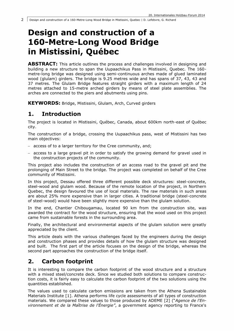
3.1. Architectural design
Figure 1: General view of the bridge
In order to span the 160 metres of the Uupaachikus pass, we chose four (4) spans of 37,
43, 43 and 37 metres. The arches had been added in order to minimise the effects of the
interior spans and adding an architectural feature, key aspect to our concept.
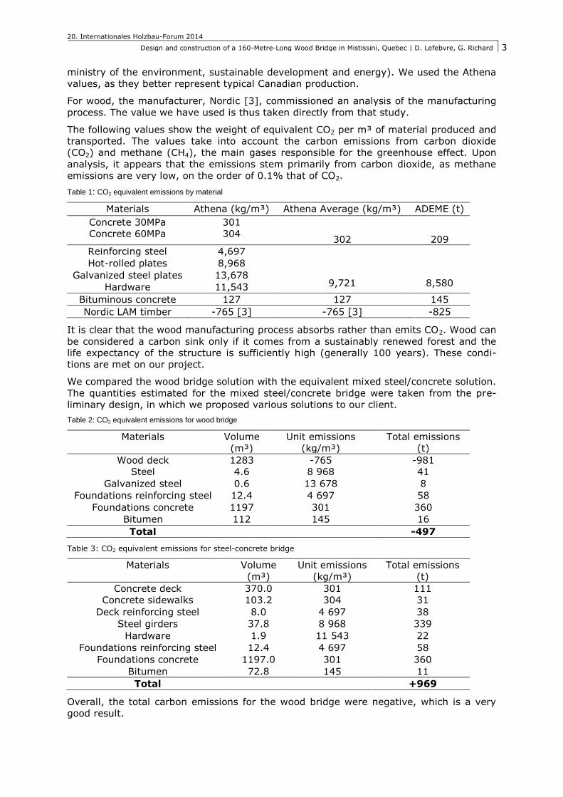
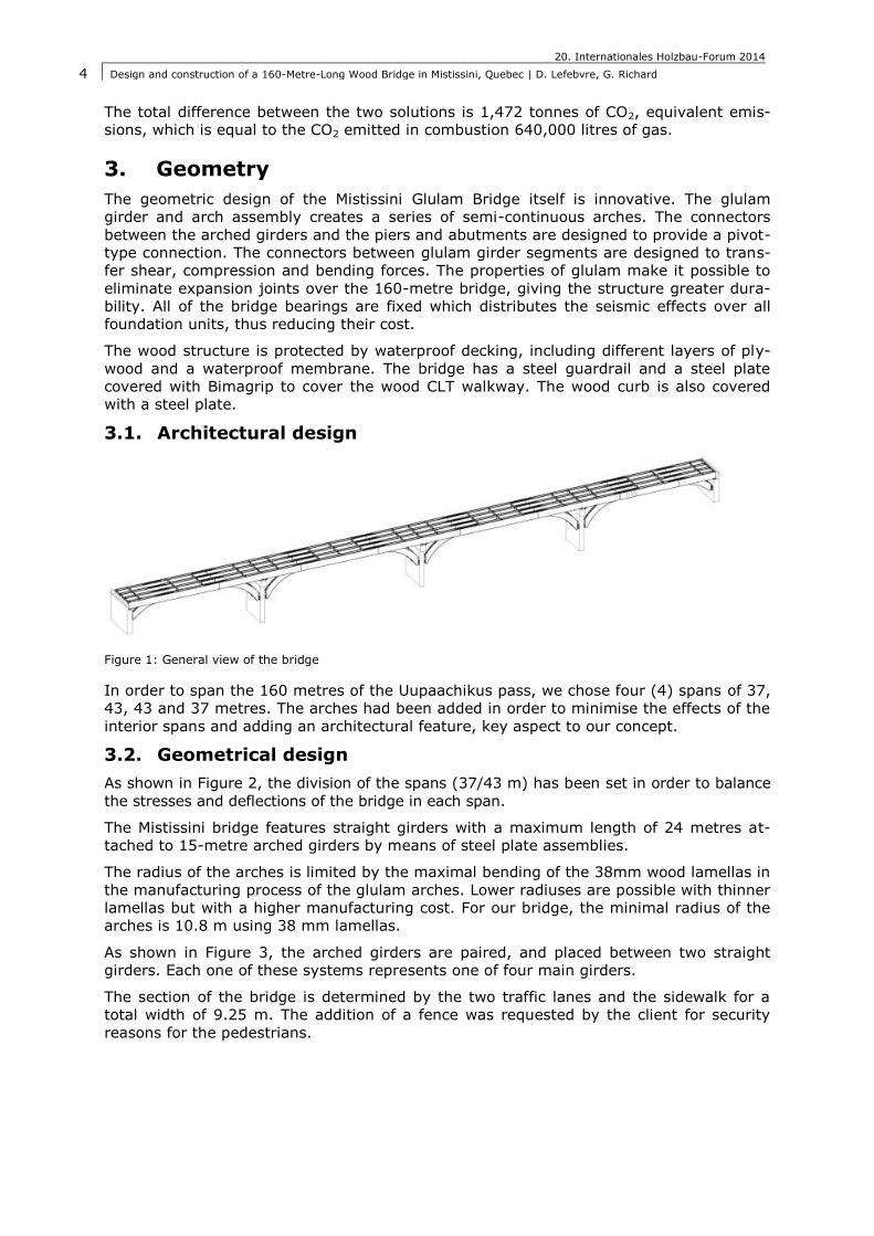
3.2. Geometrical design
As shown in Figure 2, the division of the spans (37/43 m) has been set in order to balance
the stresses and deflections of the bridge in each span.
The Mistissini bridge features straight girders with a maximum length of 24 metres at-
tached to 15-metre arched girders by means of steel plate assemblies.
The radius of the arches is limited by the maximal bending of the 38mm wood lamellas in
the manufacturing process of the glulam arches. Lower radiuses are possible with thinner
lamellas but with a higher manufacturing cost. For our bridge, the minimal radius of the
arches is 10.8 m using 38 mm lamellas.
As shown in Figure 3, the arched girders are paired, and placed between two straight
girders. Each one of these systems represents one of four main girders.
The section of the bridge is determined by the two traffic lanes and the sidewalk for a
total width of 9.25 m. The addition of a fence was requested by the client for security
reasons for the pedestrians.
20. Internationales Holzbau-Forum 2014
Design and construction of a 160-Metre-Long Wood Bridge in Mistissini, Quebec | D. Lefebvre, G. Richard
5
Figure 2: Elevation of the bridge
Figure 3: Section view of the bridge
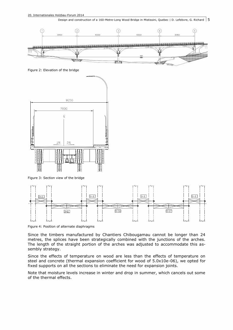
Figure 4: Position of alternate diaphragms
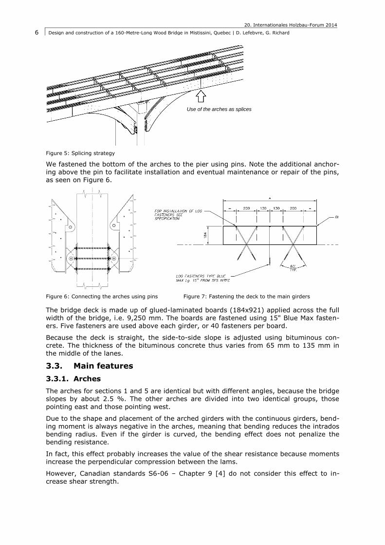
Since the timbers manufactured by Chantiers Chibougamau cannot be longer than 24
metres, the splices have been strategically combined with the junctions of the arches.
The length of the straight portion of the arches was adjusted to accommodate this as-
sembly strategy.
Since the effects of temperature on wood are less than the effects of temperature on
steel and concrete (thermal expansion coefficient for wood of 5.0x10e-06), we opted for
fixed supports on all the sections to eliminate the need for expansion joints.
Note that moisture levels increase in winter and drop in summer, which cancels out some
of the thermal effects.
20. Internationales Holzbau-Forum 2014
Design and construction of a 160-Metre-Long Wood Bridge in Mistissini, Quebec | D. Lefebvre, G. Richard
6
Figure 5: Splicing strategy
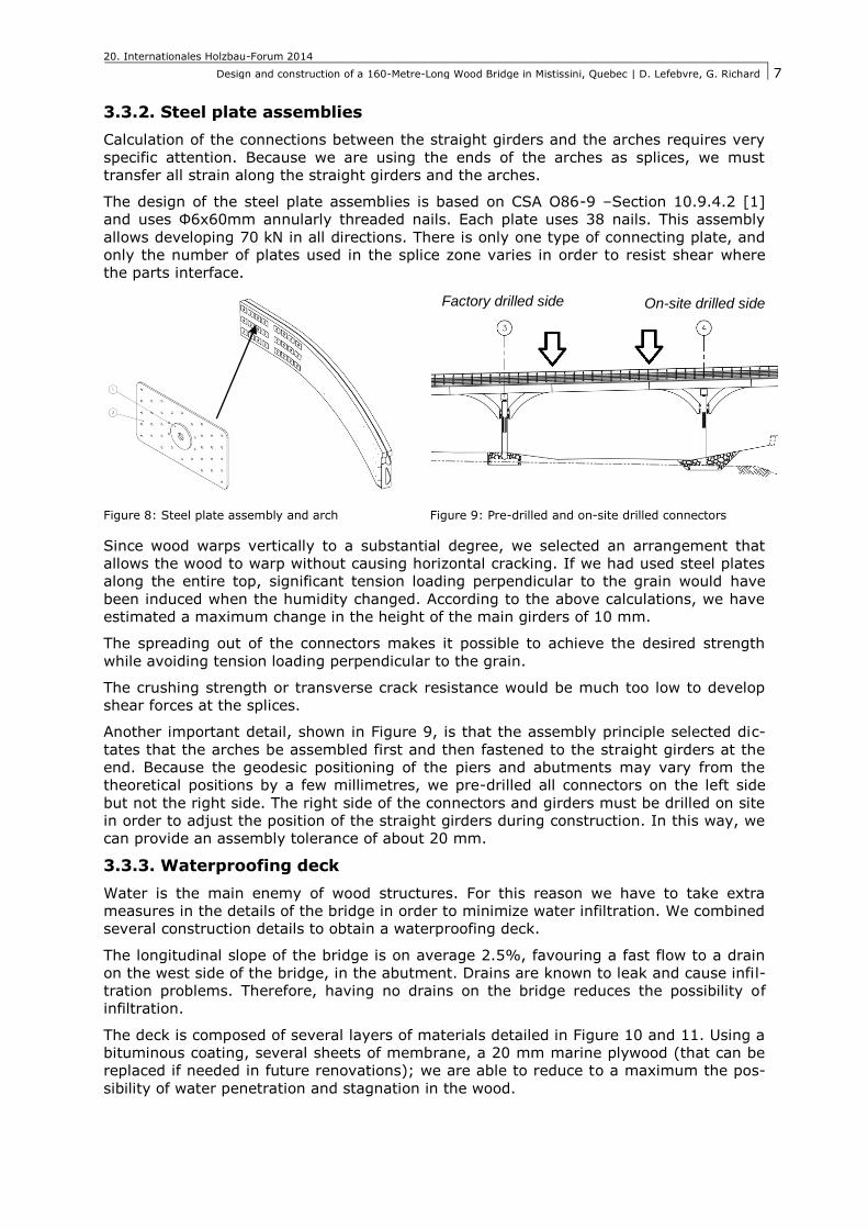
We fastened the bottom of the arches to the pier using pins. Note the additional anchor-
ing above the pin to facilitate installation and eventual maintenance or repair of the pins,
as seen on Figure 6.
Figure 6: Connecting the arches using pins Figure 7: Fastening the deck to the main girders
The bridge deck is made up of glued-laminated boards (184x921) applied across the full
width of the bridge, i.e. 9,250 mm. The boards are fastened using 15" Blue Max fasten-
ers. Five fasteners are used above each girder, or 40 fasteners per board.
Because the deck is straight, the side-to-side slope is adjusted using bituminous con-
crete. The thickness of the bituminous concrete thus varies from 65 mm to 135 mm in
the middle of the lanes.
3.3. Main features
3.3.1. Arches
The arches for sections 1 and 5 are identical but with different angles, because the bridge
slopes by about 2.5 %. The other arches are divided into two identical groups, those
pointing east and those pointing west.
Due to the shape and placement of the arched girders with the continuous girders, bend-
ing moment is always negative in the arches, meaning that bending reduces the intrados
bending radius. Even if the girder is curved, the bending effect does not penalize the
bending resistance.
In fact, this effect probably increases the value of the shear resistance because moments
increase the perpendicular compression between the lams.
However, Canadian standards S6-06 – Chapter 9 [4] do not consider this effect to in-
crease shear strength.
Use of the arches as splices
20. Internationales Holzbau-Forum 2014
Design and construction of a 160-Metre-Long Wood Bridge in Mistissini, Quebec | D. Lefebvre, G. Richard
7
3.3.2. Steel plate assemblies
Calculation of the connections between the straight girders and the arches requires very
specific attention. Because we are using the ends of the arches as splices, we must
transfer all strain along the straight girders and the arches.
The design of the steel plate assemblies is based on CSA O86-9 –Section 10.9.4.2 [1]
and uses Φ6x60mm annularly threaded nails. Each plate uses 38 nails. This assembly
allows developing 70 kN in all directions. There is only one type of connecting plate, and
only the number of plates used in the splice zone varies in order to resist shear where
the parts interface.
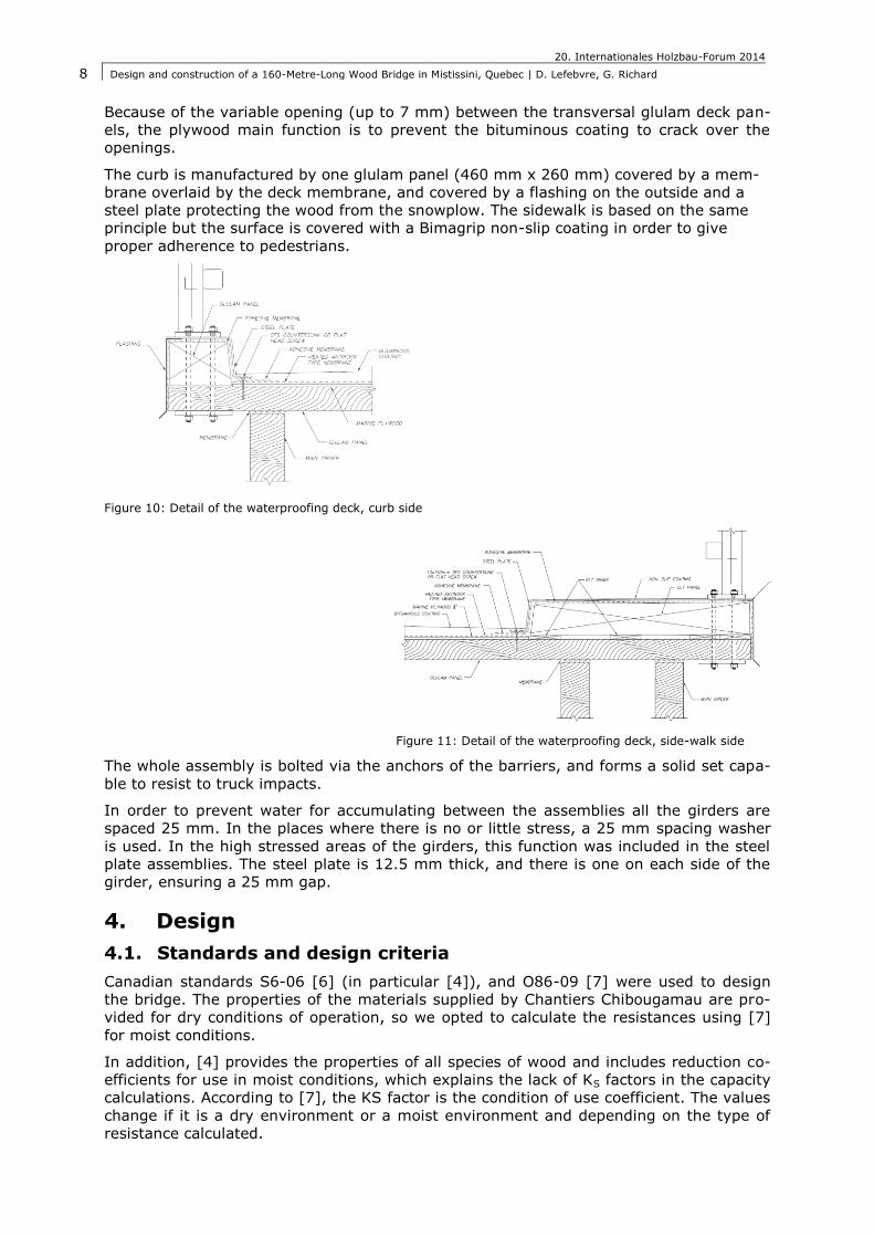
Figure 8: Steel plate assembly and arch Figure 9: Pre-drilled and on-site drilled connectors
Since wood warps vertically to a substantial degree, we selected an arrangement that
allows the wood to warp without causing horizontal cracking. If we had used steel plates
along the entire top, significant tension loading perpendicular to the grain would have
been induced when the humidity changed. According to the above calculations, we have
estimated a maximum change in the height of the main girders of 10 mm.
The spreading out of the connectors makes it possible to achieve the desired strength
while avoiding tension loading perpendicular to the grain.
The crushing strength or transverse crack resistance would be much too low to develop
shear forces at the splices.
Another important detail, shown in Figure 9, is that the assembly principle selected dic-
tates that the arches be assembled first and then fastened to the straight girders at the
end. Because the geodesic positioning of the piers and abutments may vary from the
theoretical positions by a few millimetres, we pre-drilled all connectors on the left side
but not the right side. The right side of the connectors and girders must be drilled on site
in order to adjust the position of the straight girders during construction. In this way, we
can provide an assembly tolerance of about 20 mm.
3.3.3. Waterproofing deck
Water is the main enemy of wood structures. For this reason we have to take extra
measures in the details of the bridge in order to minimize water infiltration. We combined
several construction details to obtain a waterproofing deck.
The longitudinal slope of the bridge is on average 2.5%, favouring a fast flow to a drain
on the west side of the bridge, in the abutment. Drains are known to leak and cause infil-
tration problems. Therefore, having no drains on the bridge reduces the possibility of
infiltration.
The deck is composed of several layers of materials detailed in Figure 10 and 11. Using a
bituminous coating, several sheets of membrane, a 20 mm marine plywood (that can be
replaced if needed in future renovations); we are able to reduce to a maximum the pos-
sibility of water penetration and stagnation in the wood.
On-site drilled side Factory drilled side
20. Internationales Holzbau-Forum 2014
Design and construction of a 160-Metre-Long Wood Bridge in Mistissini, Quebec | D. Lefebvre, G. Richard
8
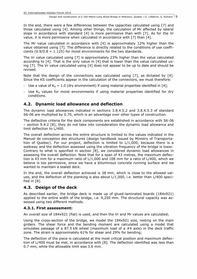
Because of the variable opening (up to 7 mm) between the transversal glulam deck pan-
els, the plywood main function is to prevent the bituminous coating to crack over the
openings.
The curb is manufactured by one glulam panel (460 mm x 260 mm) covered by a mem-
brane overlaid by the deck membrane, and covered by a flashing on the outside and a
steel plate protecting the wood from the snowplow. The sidewalk is based on the same
principle but the surface is covered with a Bimagrip non-slip coating in order to give
proper adherence to pedestrians.
Figure 10: Detail of the waterproofing deck, curb side
Figure 11: Detail of the waterproofing deck, side-walk side
The whole assembly is bolted via the anchors of the barriers, and forms a solid set capa-
ble to resist to truck impacts.
In order to prevent water for accumulating between the assemblies all the girders are
spaced 25 mm. In the places where there is no or little stress, a 25 mm spacing washer
is used. In the high stressed areas of the girders, this function was included in the steel
plate assemblies. The steel plate is 12.5 mm thick, and there is one on each side of the
girder, ensuring a 25 mm gap.
4. Design
4.1. Standards and design criteria
Canadian standards S6-06 [6] (in particular [4]), and O86-09 [7] were used to design
the bridge. The properties of the materials supplied by Chantiers Chibougamau are pro-
vided for dry conditions of operation, so we opted to calculate the resistances using [7]
for moist conditions.
In addition, [4] provides the properties of all species of wood and includes reduction co-
efficients for use in moist conditions, which explains the lack of KS factors in the capacity
calculations. According to [7], the KS factor is the condition of use coefficient. The values
change if it is a dry environment or a moist environment and depending on the type of
resistance calculated.
20. Internationales Holzbau-Forum 2014
Design and construction of a 160-Metre-Long Wood Bridge in Mistissini, Quebec | D. Lefebvre, G. Richard
9
In the end, there were a few differences between the capacities calculated using [7] and
those calculated using [4]. Among other things, the calculation of Mr affected by lateral
slope in accordance with standard [4] is more permissive than with [7]. As for the Vr
value, it is more permissive when calculated in accordance with [7] than [4].
The Mr value calculated in accordance with [4] is approximately 12% higher than the
value obtained using [7]. The difference is directly related to the conditions of use coeffi-
cients (0.9/0.8 = 1.125) for moist environments for the two standards.
The Vr value calculated using [7] is approximately 23% higher than the value calculated
according to [4]. That is the only value in [4] that is lower than the value calculated us-
ing [7]. The Vr value calculated using [4] does not appear to be up to date and should be
revised.
Note that the design of the connections was calculated using [7], as dictated by [4].
Since the KS coefficients appear in the calculation of the connectors, we must therefore:
Use a value of KS = 1.0 (dry environment) if using material properties identified in [4];
Use KS values for moist environments if using material properties identified for dry
conditions.
4.2. Dynamic load allowance and deflection
The dynamic load allowances indicated in sections 3.8.4.5.2 and 3.8.4.5.3 of standard
S6-06 are multiplied by 0.70, which is an advantage over other types of construction.
The deflection criteria for the deck components are established in accordance with S6-06
– section 9.4.2 [8]; they do not take into consideration the dynamic load allowance and
limit deflection to L/400.
The overall deflection across the entire structure is limited to the values indicated in the
Manuel de conception des structures (design handbook issued by Ministry of Transporta-
tion of Quebec). For our project, deflection is limited to L/1,000, because there is a
walkway and the deflection assessed using the vibration frequency of the bridge is lower.
Contrary to what is specified in section [8], we considered dynamic load allowances in
assessing the overall deflection. Note that for a span of 43 metres, the maximum deflec-
tion is 43 mm for a maximum ratio of L/1,000 and 108 mm for a ratio of L/400, which we
believe is too permissive, since we have a bituminous concrete running surface and we
wanted to maintain a sealed deck.
In the end, the overall deflection achieved is 38 mm, which is close to the allowed val-
ues, and the deflection of the planking is also about L/1,000, i.e. better than L/400 speci-
fied in [8].
4.3. Design of the deck
As described earlier, the bridge deck is made up of glued-laminated boards (184x921)
applied to the entire width of the bridge, i.e. 9,250 mm. The structural capacity was as-
sessed using two different methods.
4.3.1. First assessment:
An overall size of 184x921 (flat) is used, and then the Vr and Mr values are calculated;
Using the cross-section of the bridge, we model the 184x921 size, resting on the main
girders. The shear force and the bending moment are calculated using a model that
simulates passage of a 87.5 kN wheel (maximum load of a #4 axle) in the deck traffic
zone. The strain is approximately 61% for shear and 29% for bending;
The deflection of the piece is calculated at the most critical position and maximum deflec-
tion of L/400 must be met, in accordance with [8]. The deflection identified was less than
0.7 mm, while the allowable limit was 3.6 mm.
20. Internationales Holzbau-Forum 2014
Design and construction of a 160-Metre-Long Wood Bridge in Mistissini, Quebec | D. Lefebvre, G. Richard
10
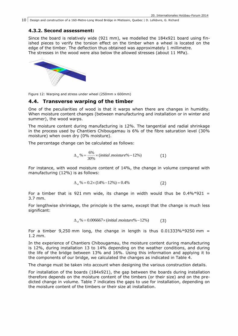
4.3.2. Second assessment:
Since the board is relatively wide (921 mm), we modelled the 184x921 board using fin-
ished pieces to verify the torsion effect on the timber when a wheel is located on the
edge of the timber. The deflection thus obtained was approximately 1 millimetre.
The stresses in the wood were also below the allowed stresses (about 11 MPa).
Figure 12: Warping and stress under wheel (250mm x 600mm)
4.4. Transverse warping of the timber
One of the peculiarities of wood is that it warps when there are changes in humidity.
When moisture content changes (between manufacturing and installation or in winter and
summer), the wood warps.
The moisture content during manufacturing is 12%. The tangential and radial shrinkage
in the process used by Chantiers Chibougamau is 6% of the fibre saturation level (30%
moisture) when oven dry (0% moisture).
The percentage change can be calculated as follows:
%)12%.(%30
%6% moistureinitialvt
(1)
For instance, with wood moisture content of 14%, the change in volume compared with
manufacturing (12%) is as follows:
%4.0%)12%14(2.0% vt (2)
For a timber that is 921 mm wide, its change in width would thus be 0.4%*921 =
3.7 mm.
For lengthwise shrinkage, the principle is the same, except that the change is much less
significant:
%)12%.(006667.0% moistureinitialvl (3)
For a timber 9,250 mm long, the change in length is thus 0.01333%*9250 mm =
1.2 mm.
In the experience of Chantiers Chibougamau, the moisture content during manufacturing
is 12%, during installation 13 to 14% depending on the weather conditions, and during
the life of the bridge between 13% and 16%. Using this information and applying it to
the components of our bridge, we calculated the changes as indicated in Table 4.
The change must be taken into account when designing the various construction details.
For installation of the boards (184x921), the gap between the boards during installation
therefore depends on the moisture content of the timbers (or their size) and on the pre-
dicted change in volume. Table 7 indicates the gaps to use for installation, depending on
the moisture content of the timbers or their size at installation.
20. Internationales Holzbau-Forum 2014
Design and construction of a 160-Metre-Long Wood Bridge in Mistissini, Quebec | D. Lefebvre, G. Richard
11
Table 4: Changes in timber sizes depending on moisture
Point in time Moisture content
(%) Dvt (%) Width of timber
(mm)
Starting moisture 12% 921
Installation moisture 14% 0.40% 925
Min. moisture (structure) 13% 0.20% 923
Max. moisture (structure) 16% 0.80% 928
Structure Max-Min 5.5
Note that if we install the timbers with no gaps during construction and the timbers have
a moisture content of 13%, knowing that the moisture of the wood tends to go a maxi-
mum of 16%, the unrestrained expansion of the planking would be 960 mm. It is there-
fore wise to include gaps during installation to avoid any damage to the structure.
Table 5: Gap between timbers according to moisture content
Moisture content (%) Width (mm) Gap (mm)
12 921 9
13 923 7
14 925 5
15 927 3
16 928 2
4.5. Steel components
Calculation of the strength of the steel bolts and plates is in compliance with the specifi-
cations of [6].
4.6. Seismic bridge design
The bridge category is "Other" in [6], which is the least demanding, and the seismic zone
is fairly low, i.e. A=0.036. The design of the foundations is thus based on R=1 and I=1.
In addition, as all the support structures are fixed, the spreading of the seismic loads is
optimal.
A multimodal spectral analysis was performed to determine the strain on the structure
and foundations.
The ice loads are higher and dictate the design of the foundations. The support structures
and pins are fixed, so they play an important role as a stabilizer against upheaval of the
foundations due to ice ride-up.
4.7. Support structures
The support structures are made of conventional bonded steel reinforced elastomeric.
The assembly is obviously different with a steel girder bridge. The vertical and transverse
loads are lower, however, because the deck is about one-third the weight of a
steel/concrete deck. In our case, because the pins take a sizeable amount of the deck
strain, the reaction of the supports is about 10% of the reaction of a steel/concrete
bridge.
4.8. Hyperstatic lifting
The arrangement of the straight girders and the arches means that lifting of the bridge
requires greater force in relation to the reaction of the support structures. For example,
on the most critical pier, the sum of the reactions due to permanent loads is 600 kN.
However, to lift the bridge at this spot by 5 mm, we would need six lifting points of
160 kN, or a total of 960 kN. The lifting force is low and creates very little strain on the
structure.
By comparison, the steel/concrete structural equivalent has a total lifting force of about
5,600 kN, more than five times the lifting value required for the wood bridge.
20. Internationales Holzbau-Forum 2014
Design and construction of a 160-Metre-Long Wood Bridge in Mistissini, Quebec | D. Lefebvre, G. Richard
12
5. Construction
5.1. Foundations
The abutments and piers are reinforced concrete and rest on shallow foundations. The
foundation soil is comprised of very rigid till.
The abutments are located on the shore of the Uupaachickus pass, whereas the founda-
tions of the piers are underwater. The use of anti-leaching concrete was mandatory in
the footings of the piers because of the water infiltration in cofferdams. The cofferdams
were then dried and led to pour the central part of the pier using standard concrete.
Due to access difficulties in the west bank of the pass, the contractor had to use a few
innovative solutions for pouring the concrete, such as placing the mixer trucks on barges
or using a helicopter to fly the concrete over the pass.
A few issues with the concrete foundations were raised, most of all imprecision of the
connections between the concrete and the wood. The anchors were offsets from 10 mm
to 50 mm in every direction depending on the foundation unit, for example abutment 1
vertical anchors offset East whereas pier 2 vertical anchors offset North-West.
Even with the design that allowed some adjustments in the assembly (pre-drilled / drilled
on-site holes, oblong holes in the anchoring plates of the arches) the contractor did not
use these adjustments to his benefit. This led to a more complicated assembly.
5.2. Manufacture of the glulam girders
Because of the remote location of the project, in Northern Quebec, the design favoured
the use of local materials. Chantier Chibougamau, located 90 km from the construction
site, was awarded the contract for the wood structure, ensuring that the wood used on
this project came from sustainable forests in the surrounding area.
The materials used in this project are Nordic Lam for glulam girders and panels, and Nor-
dic X-lam for CLT panels. Information given by Nordic:
Nordic Lam is a glue-laminated structural timber product (glulam) made of black spruce
and used as beams, headers, rafters, purlins, columns, studs and decking in buildings
and other types of construction.
Product composition on the basis of 1m3 of glulam output at the mill gate:
Wood portion: 1 m3 (417 kg on oven dry basis)
Resin: 12.34 kg (Polyurethane and isocyanate)
Lumber wrap: 0.46 kg (HDPE)
In order to ensure the best manufacturing quality, several actions were required by
Chantier Chibougamau. The main quality control was supervision from a Dessau techni-
cian, experienced in wood manufacture. This technician was on site during the main
steps of the manufacturing.
Dessau also required Chantier Chibougamau to make a full assembly of one of the main
girders, including two arches and two strait girders. This test proved that the manufac-
ture was correct and the assembly would not lead to problems during the final assembly
on-site.
Overall the manufacture of the glulam girders and deck was a success except for the
steel works, and the threaded rods in particular. These rods are the rods that transfer the
efforts from arches to girders and girders to diaphragms. Some of these rods were not
perfectly aligned, resulting in the necessity to enlarge the holes in the steel plate assem-
blies and girders. This was done on-site and led to delays in the assembly.
5.3. Assembly of the girders and deck
The erection of the girders started around pier #4. The first step of the contractor was to
assemble two straight girders, on the ground, using diaphragms. The objective of this
20. Internationales Holzbau-Forum 2014
Design and construction of a 160-Metre-Long Wood Bridge in Mistissini, Quebec | D. Lefebvre, G. Richard
13
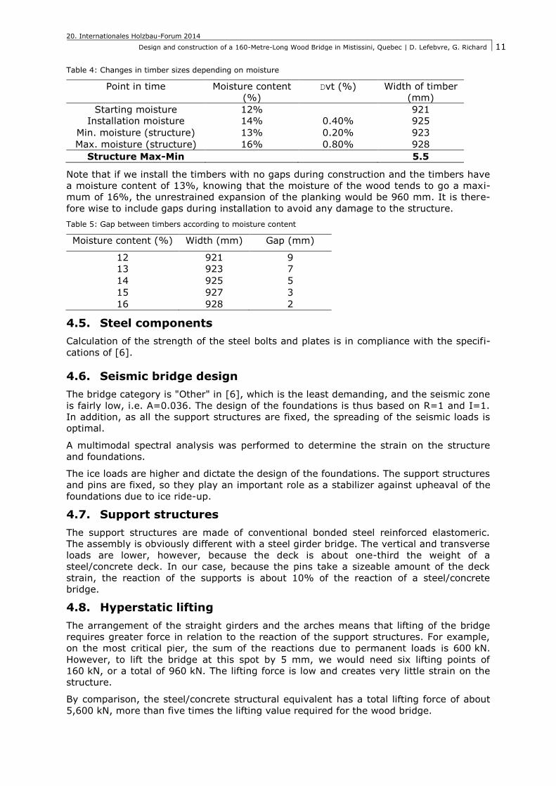
assembly is to have some lateral stability of the girders during the following steps. The
assembly is then being mounted on the pier #4, using a crane. It is placed in the correct
position using scaffolding and the arches are placed in the right position. The arches are
first pinned to the pier and then brought to the correct position using cranes. The
straights and arched girders are assembled using the rods passing through the dia-
phragms. The process is repeated until all the arches and straights girders are placed on
pier #4, as shown in Figure 13.
Figure 13: assembly completed at Pier #4
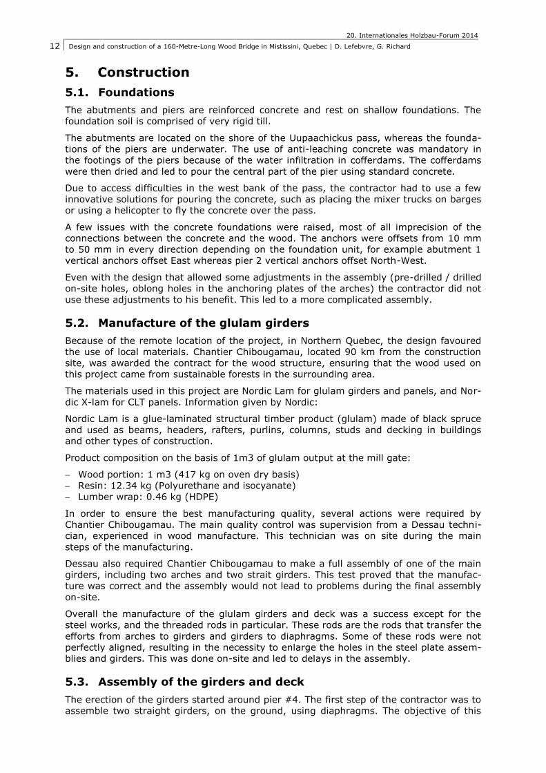
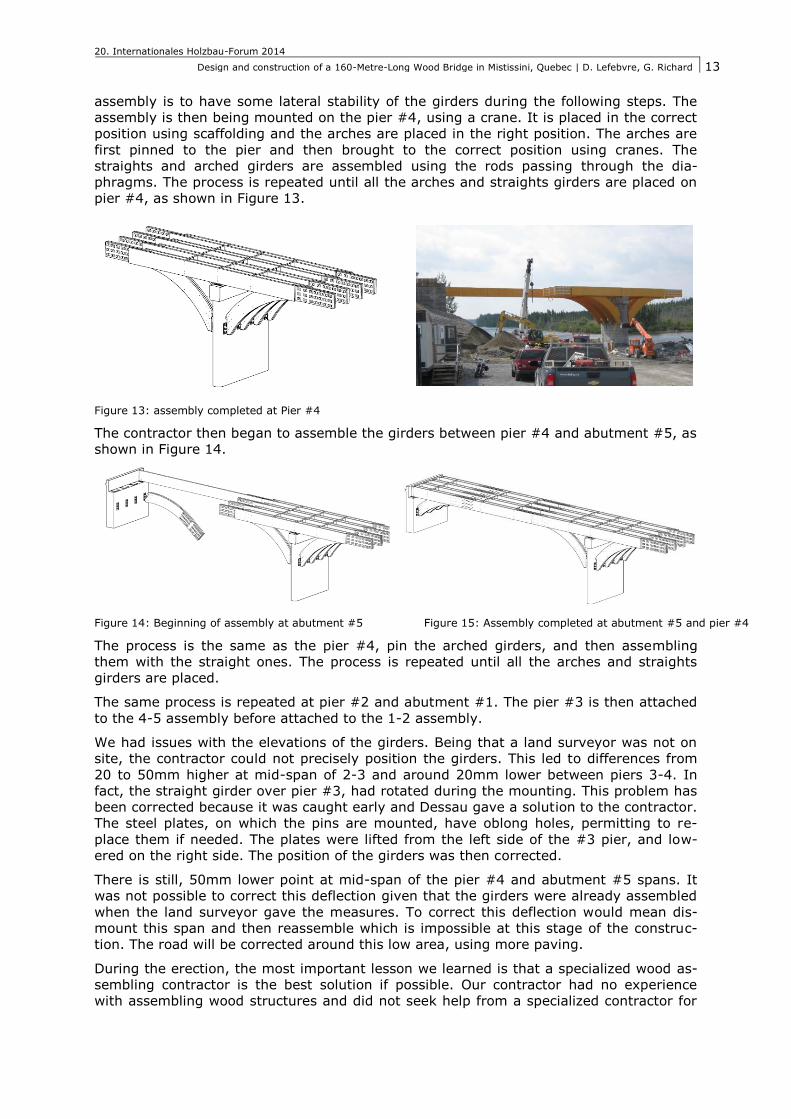
The contractor then began to assemble the girders between pier #4 and abutment #5, as
shown in Figure 14.
Figure 14: Beginning of assembly at abutment #5 Figure 15: Assembly completed at abutment #5 and pier #4
The process is the same as the pier #4, pin the arched girders, and then assembling
them with the straight ones. The process is repeated until all the arches and straights
girders are placed.
The same process is repeated at pier #2 and abutment #1. The pier #3 is then attached
to the 4-5 assembly before attached to the 1-2 assembly.
We had issues with the elevations of the girders. Being that a land surveyor was not on
site, the contractor could not precisely position the girders. This led to differences from
20 to 50mm higher at mid-span of 2-3 and around 20mm lower between piers 3-4. In
fact, the straight girder over pier #3, had rotated during the mounting. This problem has
been corrected because it was caught early and Dessau gave a solution to the contractor.
The steel plates, on which the pins are mounted, have oblong holes, permitting to re-
place them if needed. The plates were lifted from the left side of the #3 pier, and low-
ered on the right side. The position of the girders was then corrected.
There is still, 50mm lower point at mid-span of the pier #4 and abutment #5 spans. It
was not possible to correct this deflection given that the girders were already assembled
when the land surveyor gave the measures. To correct this deflection would mean dis-
mount this span and then reassemble which is impossible at this stage of the construc-
tion. The road will be corrected around this low area, using more paving.
During the erection, the most important lesson we learned is that a specialized wood as-
sembling contractor is the best solution if possible. Our contractor had no experience
with assembling wood structures and did not seek help from a specialized contractor for
20. Internationales Holzbau-Forum 2014
Design and construction of a 160-Metre-Long Wood Bridge in Mistissini, Quebec | D. Lefebvre, G. Richard
14
this part of the project. It would have probably been a more effective solution for this
complex structure. In our future projects, we will require the contractor, if possible, to
use experienced workforce in wood structures.
Furthermore, we should have requested the presence of a land surveyor on site during
the whole assembly.
5.4. End of construction works
All these small problems during the construction of the foundations and the assembly of
the glulam structure, once added led to delays that were problematic. Due to the tem-
perature when the works were finished, the deck membrane was not installed (need to
be over 0°C), as well as the paving. This resulted in the inability for the client to use the
bridge in the winter.
All the on-site works are suspended during the winter 2013/2014, due to weather condi-
tions. All works have been completed in the spring/summer 2014.
A series of inspections will occur before on-site works resume in order assessing the po-
tential damages due to water infiltration, because of the absence of the membrane.
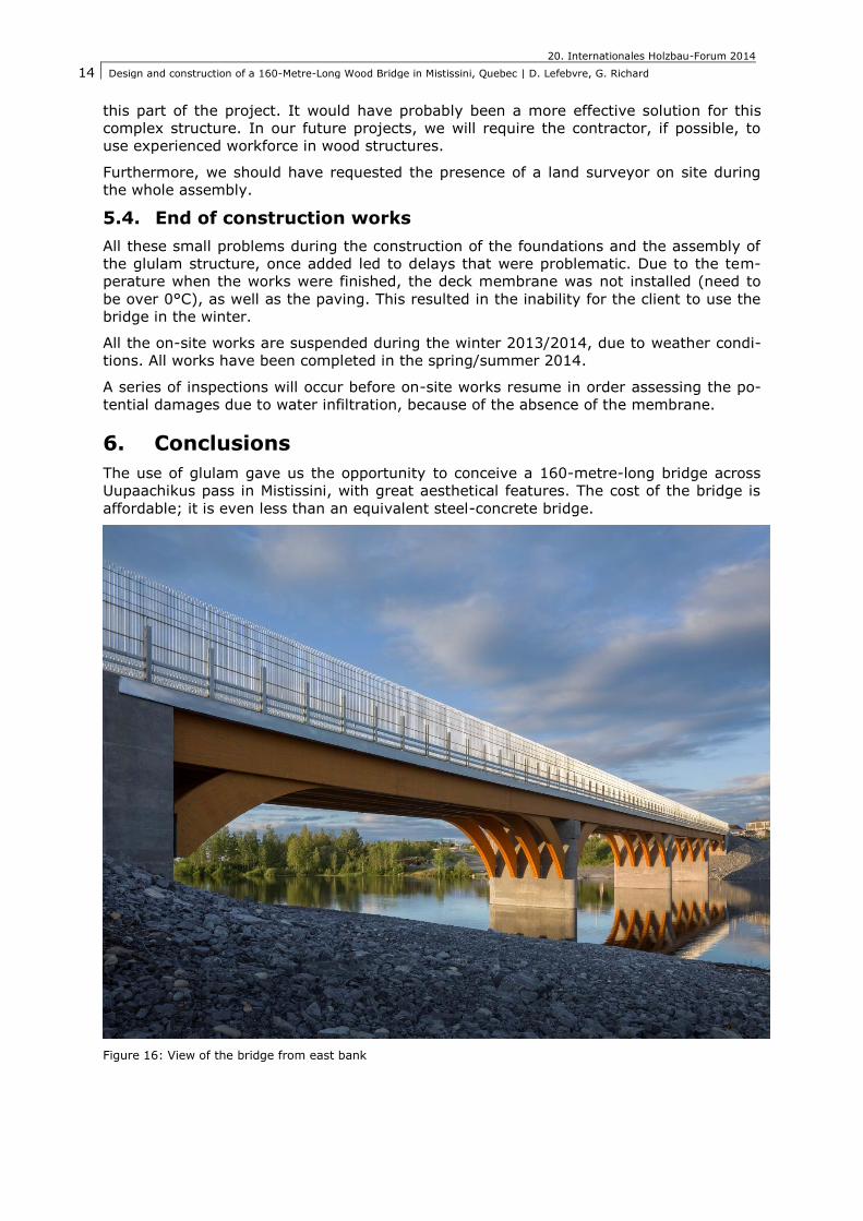
6. Conclusions
The use of glulam gave us the opportunity to conceive a 160-metre-long bridge across
Uupaachikus pass in Mistissini, with great aesthetical features. The cost of the bridge is
affordable; it is even less than an equivalent steel-concrete bridge.
Figure 16: View of the bridge from east bank
20. Internationales Holzbau-Forum 2014
Design and construction of a 160-Metre-Long Wood Bridge in Mistissini, Quebec | D. Lefebvre, G. Richard
15
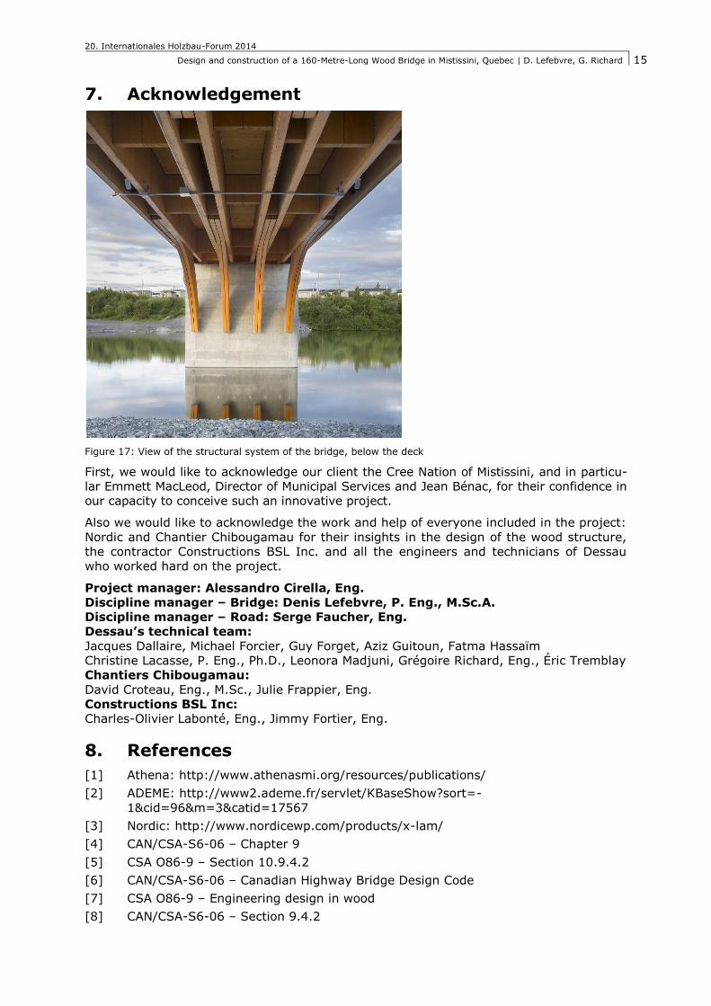
7. Acknowledgement
Figure 17: View of the structural system of the bridge, below the deck
First, we would like to acknowledge our client the Cree Nation of Mistissini, and in particu-
lar Emmett MacLeod, Director of Municipal Services and Jean Bénac, for their confidence in
our capacity to conceive such an innovative project.
Also we would like to acknowledge the work and help of everyone included in the project:
Nordic and Chantier Chibougamau for their insights in the design of the wood structure,
the contractor Constructions BSL Inc. and all the engineers and technicians of Dessau
who worked hard on the project.
Project manager: Alessandro Cirella, Eng.
Discipline manager – Bridge: Denis Lefebvre, P. Eng., M.Sc.A.
Discipline manager – Road: Serge Faucher, Eng.
Dessau’s technical team:
Jacques Dallaire, Michael Forcier, Guy Forget, Aziz Guitoun, Fatma Hassaïm
Christine Lacasse, P. Eng., Ph.D., Leonora Madjuni, Grégoire Richard, Eng., Éric Tremblay
Chantiers Chibougamau:
David Croteau, Eng., M.Sc., Julie Frappier, Eng.
Constructions BSL Inc:
Charles-Olivier Labonté, Eng., Jimmy Fortier, Eng.
8. References
[1] Athena: http://www.athenasmi.org/resources/publications/
[2] ADEME: http://www2.ademe.fr/servlet/KBaseShow?sort=-
1&cid=96&m=3&catid=17567
[3] Nordic: http://www.nordicewp.com/products/x-lam/
[4] CAN/CSA-S6-06 – Chapter 9
[5] CSA O86-9 – Section 10.9.4.2
[6] CAN/CSA-S6-06 – Canadian Highway Bridge Design Code
[7] CSA O86-9 – Engineering design in wood
[8] CAN/CSA-S6-06 – Section 9.4.2