Embed Size (px)
Citation preview

Design and Calibration of a Double-directional 60 GHz
Channel Sounder for Multipath Component Tracking* Ruoyu Sun1, Peter B. Papazian1, Jelena Senic1, Yeh Lo1, Jae-Kark Choi2, Kate A. Remley1, Camillo Gentile2
1RF Technology Division, National Institute of Standards and Technology, Boulder, CO, USA, [email protected] 2Wireless Networks Division, National Institute of Standards and Technology, Gaithersburg, MD, USA
*Publication of the United States government, not subject to copyright in the U.S.
Abstract—The 60 GHz band is being considered for many
high-bandwidth wireless applications. To support standards development for these applications, NIST has developed an
untethered 60 GHz, 8×16 MIMO channel sounder. It employs a pseudorandom bit sequence with a bandwidth of 4 GHz. The sounder can precisely measure radio propagation channel
characteristics such as path loss, small-scale fading, delay dispersion, absolute delay, angle-of-arrival (AoA), angle-of-departure (AoD), and Doppler power spectrum. Its ability to
measure the time dynamics of the millimeter-wave radio channel, when untethered and in motion, is unique. It employs electronically-switched MIMO antenna arrays, a robot for
moving measurements and an automated one-dimensional positioner for precision measurements at fixed locations. Sounder performance is improved by use of pre-distortion
filters and precision calibration of the RF and timing systems. Data showing initial AoD and AoA estimation error are presented along with initial test results for ground-plane
reflection.
Index Terms—mmWave, MIMO, channel; measurement.
I. INTRODUCTION
In July 2016, the Federal Communications Commission
(FCC) granted approval of licensed operation in new 28, 37,
and 39 GHz bands and extended the unlicensed 60 GHz band
from 57 – 71 GHz, releasing in total about 11 GHz of
millimeter-wave (mmWave) spectrum [1]. The band at 95
GHz is also currently under review. The order was prompted
by the saturation of the sub-6 GHz allocations over the past
decade, in particular by data-intensive smartphones. Although
less favorable in terms of propagation, the new bands will
admit channel bandwidths three orders of magnitude wider;
indeed, the IEEE 802.11ay standardization efforts in process
have already provisioned for 4.4 GHz channels to support use
cases including outdoor backhaul, wireless server backup,
augmented reality headsets, and mass video distribution [1].
More than a simple shift in center frequency, mmWave
communication systems embody a significant departure in
technology from their predecessors. The tiny wavelengths
relax the conditions for implementing phased-array antennas
with tens to hundreds of elements on a mobile handset (as well
as at the base station). The massive arrays can synthesize
extremely narrow beams on the order of degrees. The purpose
is, through their associated gain in excess of 30 dBi, to
compensate for the greater path loss witnessed in the upper
spectrum. In order for beamforming to take full advantage of
the propagation environment, channel sounding will allow a
base station and user device to jointly determine which angles-
of-departure (AoDs) and angles-of-arrival (AoAs) correspond
to viable transmission paths. The beams will then be steered
in those multipath directions. Frequent updating of the channel
state through multipath component tracking will be necessary
in mobile environments to avoid the beams falling out of
alignment with the multipaths. Hence multipath tracking
represents a novel but critical aspect of mmWave channel
propagation modeling.
To help meet the demands of these next-generation
models, NIST has designed the 60 GHz channel sounder
described in this paper. The three-dimensional antenna arrays
at the transmitter (TX) and receiver (RX) permit extraction of
double-directional multipath components in both azimuth and
elevation. By virtue of the electronically-switched arrays, a
complete channel measurement can be realized in just 262 µs.
Combined with the untethered design enabled by
synchronization through rubidium clocks, mobile
environments up to a closing speed of 35 km/h can be
characterized. Finally, the 4 GHz null-to-null bandwidth of the
system can accommodate the use cases anticipated for
mmWave systems.
II. SYSTEM DESIGN
A. Overview
The 60 GHz sounder system has design features which are
similar to the 83 GHz sounder described in [2]-[4]. As with
the E-band system, it utilizes a pseudorandom bit sequence
(PRBS) to measure the complex channel impulse response
(CIR), a 16-element antenna array with fast switching
multiplexer (MUX) at the receiver, and a mobile positioner to
provide position information and mapping. In contrast to the
single transmit antenna, this 60 GHz system has an 8-element
switched array. Thus, the MIMO capability allows
measurement of AoD as well as AoA. Both antenna arrays use
scalar feed horns (SFHs) which have symmetrical patterns,
maximum gain of 18.1 dBi and side-lobe levels below -10 dBi.
This is important when combining patterns in an array
processing program and making use of the space-alternating
generalized expectation-maximization (SAGE) algorithm [5]
to calculate the equivalent omni-directional CIRs. In addition
to its mobile measurement capabilities, a one-dimensional (1-
D) positioner has been added for stationary measurements at
sub-wavelength increments. The system parameters as well as
additional calibration methods are discussed in the following
sections.
B. Transmitter and Receiver
The TX utilizes an arbitrary waveform generator (AWG)
with a sampling rate of 12 Gsamples/s. The AWG generates a
2017 11th European Conference on Antennas and Propagation (EUCAP)
978-88-907018-7-0/17/$31.00 ©2017 IEEE #15703145503336

3-GHz intermediate frequency (IF) signal with BPSK
modulation with a 2047-bit pseudorandom (PN) code word.
The bit (or chip) rate is 2 Gbits/s, yielding a delay resolution
of 0.5 ns and a maximum delay span of 1023.5 ns. The RF
section then up-converts the IF signal to 60.5 GHz. The
maximum transmit power for the TX MUX amplifiers is 20
dBm.
The RX MUX has 16 low-noise amplifiers (LNAs) with
noise figures < 5 dB. The MUX output is down-converted to
3 GHz, amplified, and then digitized at 40 Gsamples/s. The
analog-to-digital converter (ADC) is 8 bit with a
programmable IF amplifier. The raw IF data for all 128
channels are then stored on a solid-state drive along with
location information from the positioners. The dynamic range
of the system for path-loss measurements is 162.2 dB1. We
synthesized the omni-directional CIR by combining 128
directional CIRs using the SAGE algorithm. The maximum
CIR or power delay profile (PDP) updated rate is 488,519
CIRs per second, or 3816 CIRs per second for omni-
directional CIRs. The maximum CIR update rate is only
available for a short duration until the memory in the digitizer
is full.
The MIMO antenna arrays are shown in Fig. 1. The half
power beamwidth of the SFHs is 22.5. The TX multiplexer
has 8 antennas which covers 180 in the azimuthal plane
(adjacent antennas are 22.5 apart). The RX MUX includes 16
antennas that provide 360 azimuth coverage. Odd antennas
have zero elevation angles, while even indices are tilted up (or
tilted down depending on test cases) by 22.5 to provide
elevation plane coverage. The RX MUX has a second
configuration which allows both hemispheres of the antenna
arrays to be stacked vertically. In this configuration, the angle
between antennas is reduced to 11.25°, and the antennas are
replaced with 11.25° beamwidth, 25 dBi gain SFHs. This
increases the dynamic range to 169 dB while allowing greater
angular resolution.
The MUXs are electronically-switched and controlled by
the synchronization and timing circuits. The switching time is
less than 25 ns for both TX and RX MUXs. To avoid switch
1 This is determined for the 0.1 dB saturate TX power for the power
amplifiers (+20 dBm) + antenna gains (36.2 dB) – RX Noise floor (-78 dBm
ktB + LNA noise figure 5 dB) + processing gain (33 dB).
rise-and-fill times, two CIRs (2047 ns) are collected but only
one CIR (1023.5 ns) is extracted for channel modeling.
C. Positioning Systems
A mobile positioner is used for mobile measurements, and
a 1-D positioner is developed for static test cases. Figure 2(a)
shows the TX MUX mounted on a tripod at ceiling height to
simulate a Wi-Fi deployment in a server room. The RX MUX
is mounted on the mobile positioner and is ready to make an
automated measurement.
Figure 2(b) is the RX MUX and precision 1-D positioner
on a metal ground plane. The TX MUX was also positioned
on the ground plane at a fixed point. This configuration was
used to measure the two-ray channel. The precision 1-D
positioner was used to move the receiver in one-wavelength
steps, relative to the transmitter. This allowed local moving
averaging to remove small-scale fading, as well as
characterization of the reflected signals from the metal ground
plane. Results of a two-ray ground bounce response is given
in Section IV.B. The 1-D positioner has a minimum step size
of 6.35 μm and a range of 30 cm.
III. SYSTEM CALIBRATION
A. Pre-distortion Filters
In order to compensate for the non-ideal hardware transfer
functions of the transmitter and receiver chains, system
calibration is necessary. In previous work related to our 83
GHz system, a post-distortion filter was implemented [3]. Pre-
distortion filtering, however, is preferable because it can be
applied to high signal-to-noise ratio data at the transmitter.
This avoids increasing the noise level at the receiver. The pre-
distorted signal is generated by the AWG as well.
Since the amplifiers and waveguides of the TX and RX
MUX chains are slightly different, the 128 channels must be
equalized individually. Let the measured baseband frequency
response of the 𝑖𝑡ℎ transmitter and 𝑗𝑡ℎ receiver chain be:
𝑌𝑖𝑗(𝑓) = 𝑊𝑖𝑗(𝑓) ⋅ 𝑃(𝑓) ⋅ 𝐻𝑖𝑇𝑋(𝑓) ⋅ 𝐺𝑖
𝑇𝑋(𝑓) ⋅ 𝐻𝑖𝑗(𝑓)
⋅ 𝐺𝑗𝑅𝑋(𝑓) ⋅ 𝐻𝑗
𝑅𝑋(𝑓) + 𝑁(𝑓), (1)
(a)
(b)
Fig. 2. Positioning system (a) TX MUX on a tripod and RX MUX on the robotic
positioner (for moving cases); (b) RX MUX on a 1-D positioner (for static cases).
Fig. 1. Photos of TX MUX (upper left), RX MUX (right) on top of Robot
and horn antenna (lower left).
2017 11th European Conference on Antennas and Propagation (EUCAP)
#15703145503337

where 𝑊𝑖𝑗(𝑓) denotes the pre-distortion filter, 𝑃(𝑓) = 𝑝(𝑓) ⋅
𝑝∗(𝑓) the matched-filter response of the ideal PN sequence
𝑝(𝑓) , 𝐻𝑖𝑇𝑋(𝑓) and 𝐺𝑖
𝑇𝑋(𝑓) the respective transfer function
and antenna pattern of the transmitter and 𝐻𝑗𝑅𝑋(𝑓) and
𝐺𝑗𝑅𝑋(𝑓) the same for the receiver, 𝐻𝑖𝑗(𝑓) the channel transfer
function, and 𝑁(𝑓) the system noise. The calibration is based
on a back-to-back (B2B) method [6]. In this method, the
antennas are removed (𝐺𝑖𝑇𝑋 = 𝐺𝑗
𝑅𝑋 = 1) and the TX and RX
connected directly through waveguides and attenuators such
that 𝐻𝑖𝑗 = 𝐴. The B2B measurement then follows from (1) as:
𝑌𝑖𝑗𝐵2𝐵(𝑓) =
1
𝑀∑ 𝑌𝑖𝑗
𝑚(𝑓; 𝐺𝑖𝑇𝑋 = 𝐺𝑗
𝑅𝑋 = 1; 𝐻𝑖𝑗 = 𝐴)
𝑀
𝑚=1
≈ 𝑊𝑖𝑗(𝑓) ⋅ 𝑃(𝑓) ⋅ 𝐻𝑖𝑇𝑋(𝑓) ⋅ 𝐴 ⋅ 𝐻𝑗
𝑅𝑋(𝑓).
(2a)
(2b)
Averaging in (2a) over 𝑀 samples indexed through 𝑚 is
carried out to virtually eliminate noise such that the
approximation in (2b) holds; we found that 𝑀 = 128 was
sufficient.
The design criteria for the pre-distortion filter is that the
output of the B2B measurement be the ideal matched-filter
response (plus the attenuators), or
𝑌𝑖𝑗𝐵2𝐵(𝑓) = 𝐴 ⋅ 𝑃(𝑓). (3)
Now for convenience, (2b) can be rewritten as
𝑌𝑖𝑗𝐵2𝐵(𝑓) ≈ 𝑊𝑖𝑗(𝑓) ⋅ 𝑌𝑖𝑗
𝐵2𝐵(𝑓; 𝑊𝑖𝑗 = 1).
(4)
By equating (3) and (4), the solution for the pre-distortion
filter is given as
𝑊𝑖𝑗(𝑓) =𝐴 ⋅ 𝑃(𝑓)
𝑌𝑖𝑗𝐵2𝐵(𝑓; 𝑊𝑖𝑗 = 1)
. (5)
What remains is to take a B2B measurement with no filter
𝑌𝑖𝑗𝐵2𝐵(𝑓; 𝑊𝑖𝑗 = 1); i.e., with the ideal PN sequence applied at
the input.
Fig. 3 displays the power spectrum, |𝑌𝑖𝑗𝐵2𝐵(𝑓)|
2 both with
and without filtering for 𝑖 = 𝑗 = 2. Notice that the spectrum
becomes much smoother with the filter. Also displayed in Fig.
4 is the equivalent power-delay profile
|ℱ−1[𝑌𝑖𝑗𝐵2𝐵(𝑓)]|
2normalized to a peak value of 0 dB. The
filter reduces the non-ideal lobes by more than 50 dB from the
peak.
Under the assumption of a non-linear system, multiple
filter stages can be realized. In each stage, the output of the
previous stage is fed to the AWG and the filter is computed
recursively as
𝑊′′𝑖𝑗(𝑓) =
𝐴 ⋅ 𝑃(𝑓)
𝑌𝑖𝑗𝐵2𝐵 (𝑓; 𝑊𝑖𝑗 = 𝑊′
𝑖𝑗)
.
(6)
Also displayed in Figs. 3 and 4 are results up to stage three.
Although mild improvement in performance is observed, the
system indeed is close to linear and so, to simplify the process,
one-stage pre-distortion filters are employed in our system.
To simplify this process further, a calibration matrix
approach is used [7]. Through this method, we can reduce the
number of measurements from 128 to just 23 by measuring
𝑌𝑖𝑖𝐵2𝐵(𝑓; 𝑊𝑖𝑖 = 1), 𝑖 = 1 … 8 and 𝑌1𝑗
𝐵2𝐵(𝑓; 𝑊1𝑗 = 1), 𝑗 =
2 … 16. The measurements are applied to compute the filters
as
𝑊𝑖𝑗(𝑓) =𝐴 ⋅ 𝑃(𝑓) ⋅ 𝑌1𝑖
𝐵2𝐵(𝑓; 𝑊1𝑖 = 1)
𝑌𝑖𝑖𝐵2𝐵(𝑓; 𝑊𝑖𝑖 = 1) ⋅ 𝑌1𝑗
𝐵2𝐵(𝑓; 𝑊1𝑗 = 1).
(7)
The calibration matrix method may be particularly useful for
Massive-MIMO transfer functions when the number of
channels is in the hundreds or thousands. The results were
spot-checked by measuring several additional transfer
functions. Both measured and calculated transfer functions
yielded similar results.
Note that the AWG must generate 128 different
waveforms (due to 128 filters) and that the duration of each
code word lasts 2047 ns. This requires precision
synchronization between the TX and RX to ensure the RX
antenna switching is synchronized with the start of a frame of
code words. This synchronization is discussed in Section
III.C. We also found that the TX MUX needs to warm up to a
constant temperature of approximately 35 C before
measurements, because temperature affects the TX power and
the pre-distortion filter performance.
Fig. 3. Power spectrum with and without pre-distortion filter for the
2nd TX antenna and 2nd RX antennas using B2B calibration.
Fig. 4. Example individual normalized power-delay profiles with and
without the pre-distortion filter for the 2nd TX antenna and 2nd RX antenna
using B2B calibration.
2017 11th European Conference on Antennas and Propagation (EUCAP)
#15703145503338
The geometries of the TX and RX arrays play an essential
role in the precise estimation of AoA and AoD. To accurately
measure the array aperture constellation relative to its
reference center, a laser interferometer was used as described
in [8]. This system has a precision of 50 µm.
B. Multiplexer Timing Synchronization
We measured multipath delay using the time lag properties
of the PN sequence correlation function. This is a random
value without any synchronization between the AWG, RX
MUX, TX MUX and digitizer trigger. RX MUX antennas
switch once per two code words (2047 ns). This avoids
processing code word data during the MUX switching period.
The TX multiplexer switches at increments of 32 code words
to provide a two code-word window for each of the 16 RX
MUX channels. Since the pre-distortion filters make each of
the 128 transmitted signals unique, the start times must be
aligned between the transmitter code word i=1 and the RX
receiver acquisition j=1.
We achieved alignment using a two-stage synchronization
approach termed coarse sync and fine sync. The AWG
provides start triggers for both TX MUX timing circuitry
which uses a 3-bit word to access each of the 8 channels as
well as the RX MUX digital switching signal which is a 4-bit
word to access each of the 16 channels. This is termed coarse
sync, and reduces the random delay to within 2047 ns.
However, the AWG itself and the divider/counter module in
the RX introduce a random delay between zero and 2047 ns.
Hence, we use the pulses from the divider/counter module in
the RX to trigger the AWG, and termed fine sync. This
removes the random delay between zero and 2047 ns. The
coarse sync aligns the indices of code words (but not
boundaries) of the TX and RX antenna switching time slots
and the fine sync aligns the boundaries (but not indices).
Combination of the coarse and fine synchronization provides
the required switching synchronization. The synchronization
cables can now be removed and timing stability is maintained
with rubidium clocks.
The same circuitry, using internal counters, provides a
digitizer trigger which is aligned with code word i=j=1, but is
repeated at integer numbers of 256 code words. This allows
impulses for all channels to be recorded at programmable
repetition rates with a granularity of 262 µs and preserve both
channel alignment and fine synchronization. The cable length
difference and some non-ideal electronic device delays
introduce some delay biases. We compensate for these biases
by adjusting the start triggers generated by the AWG. Merging
Global Positioning System (GPS) into our synchronization
circuitries for outdoor measurements is under development.
The coarse synchronization is expected to be replaced by the
GPS.
IV. SYSTEM PERFORMANCE VERIFICATION AND INITIAL
RESULTS
Initial data from the channel sounder includes AoA and
AoD measurements, and a laboratory measurement of a two-
ray channel (a direct signal with a ground reflected signal).
We also discuss short-term time stability measurements.
A. AoA and AoD
The AoA and AoD of the direct multipath component were
measured in line-of-sight conditions. The experiments were
conducted on a 7 m by 7 m ground plane in a 10 m by 15 m
room with cinder block walls [4]. The transmitter was set on a
tripod at a height of 2.5 m and the receiver was set on the
robotic positioner at a height of 1.5 m. Using the robot’s
navigation system, we could accurately determine the relative
angle (heading) between the TX MUX antenna array and the
RX MUX antenna array as well as the velocity of the RX with
respect to the TX. The set of experiments consisted of moving
the robot in a grid pattern on the ground plane from the fixed
transmitter. At each position, the robot collected multiple
bursts of data consisting of all 128 antenna channels. We used
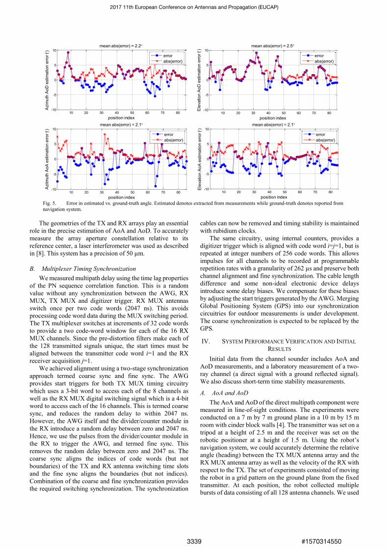
Fig. 5. Error in estimated vs. ground-truth angle. Estimated denotes extracted from measurements while ground-truth denotes reported from
navigation system.
10 20 30 40 50 60 70 80-10
-5
0
5
10
position index
Azim
uth
Ao
D e
stim
atio
n e
rro
r ( )
mean abs(error) = 2.2
10 20 30 40 50 60 70 80-10
-5
0
5
10
position index
Ele
va
tio
n A
oD
estim
atio
n e
rro
r ( )
mean abs(error) = 2.5
10 20 30 40 50 60 70 80-10
-5
0
5
10
position index
Azitm
uth
Ao
A e
stim
atio
n e
rro
r ( )
mean abs(error) = 2.1
10 20 30 40 50 60 70 80-10
-5
0
5
10
position indexE
leva
tio
n A
oA
estim
atio
n e
rro
r ( )
mean abs(error) = 2.1
error
abs(error)
error
abs(error)
error
abs(error)
error
abs(error)
2017 11th European Conference on Antennas and Propagation (EUCAP)
#15703145503339

the SAGE algorithm to estimate the AoA and AoD on an
angular grid with better resolution than our antenna angular
separation. The comparison between measured values and the
known transmitter/receiver angle for the direct path is given in
Fig. 5. We see the SAGE estimations of AoA and AoD have
an average error in azimuth less than 2.2° and in elevation less
than 2.5°.
Fig. 6 Two-Ray channel path loss measurement showing good
agreement with the theoretical model after applying the phase center
correction.
B. Two-Ray Measurements
We collected two-ray data using the precision 1-D
positioner with the transmitter and receiver positioned over a
conducting ground plane, see Fig. 2(b). The positioner was
configured for measurements at one-wavelength spacing for
60 wavelengths. The antennas were vertically oriented and
19.84 cm above the ground plane. By precisely aligning the
TX and RX antennas at boresight and adjusting the separation
to 1 m, we were able to measure the two-ray lobing pattern of
the path loss (PL) caused by the change in the direct and
reflected signal path length. This change in path length causes
the signals to add constructively or destructively over several
phase rotations or cycles, as shown in Fig. 6. Using the
geometry of the paths as the 1-D positioner moved and
accounting for the antenna patterns, we compared the
measured and calculated results. As we can see in Fig. 6, there
is an excellent fit. We see the period of the lobing pattern is
approximately 0.1 m and its magnitude is 3 dB near 1.25
meters. This increase in lobing magnitude occurred as the
reflected path antenna gain increases over link distance due to
a decreasing angle relative to the antenna boresight.
We first calculated the antenna separation by measuring
the distance between antenna aperture faces, see the green
dashed line in Fig. 6. However, the true phase center is inside
the horn antenna, which increased the link distance. We
obtained the best fit by increasing the measured separation by
1 cm, indicating the location of the phase center of the
antennas. By dividing the distance in half, we estimated that
the phase center of each antenna is 5 mm behind the antenna
aperture. This is useful because it will help in the AoA and
AoD estimation with the SAGE algorithm. We have not
applied this correction to the AoA and AoD results presented
in this paper.
C. Time Stability
The short-term time stability of the CIR is a key
characteristic of a channel-sounder measurement which is
important for calculation of AoA and AoD. We estimated this
by recording 500 CIRs in the B2B configuration. The CIRs
were spaced at 2 µs intervals, the period was 1 ms. The data
were analyzed by tabulating the phase at the peak of the CIRs.
After converting these phase values back to time, we found
that the times at the peak were Gaussian distributed with a
standard deviation of 8 ps.
V. CONCLUSION
An untethered 60 GHz MIMO channel sounder has been
developed at NIST. The 8×16 MIMO antennas are
electronically-switched. The null-to-null bandwidth is 4 GHz,
yielding a delay resolution of 0.5 ns. The timing and
synchronization enable the employment of a custom pre-
distortion for each of the 128 MIMO channels, as well as
absolute delay. The sounder has undergone extensive
calibration and synchronization. Preliminary measurement
results indicate AoA and AoD can be measured with an
average error of less than 2.5°. The sounder has been used to
measure rack-top-to-rack-top CIRs and inter-rack CIRs with
full AoA and AoD capability. These data will be presented in
a sequel and could also be used to develop IEEE 802.11ay
standards. Future work includes noise analysis and
thresholding, developing a positioning system with a new
robot and GPS for outdoor environments, detailed analysis of
phase stability, and practical characterization of antennas.
REFERENCES
[1] Federal Communication Commission, Report and Order FCC-16-89, July 14, 2016.
[2] P. B. Papazian, K. A. Remley, C. Gentile and N. Golmie, "Radio channel sounders for modeling mobile communications at 28 GHz, 60 GHz and 83 GHz," 2015 Global Symposium On Millimeter Waves (GSMM), pp. 1-3, Montreal, QC, 2015.
[3] P. B. Papazian, J. Choi, J. Senic, P. Jeavons, C. Gentile, N. Golmie, R. Sun, D. Novotny, K. A. Remley, "Calibration of millimeter-wave channel sounders for super-resolution multipath component extraction," 2016 10th European Conference on Antennas and Propagation (EuCAP) , pp. 1-5, Davos, Switzerland, 2016.
[4] P. B. Papazian, C. Gentile, K. A. Remley, J. Senic, N. Golmie, "A Radio Channel Sounder for Mobile Millimeter-Wave Communications: System Implementation and Measurement Assessment," IEEE Transactions on Microwave Theory and Techniques, Early View, vol.PP, no.99, pp.1-9, Aug. 2016.
[5] J. A. Fessler and A. O. Hero, "Space-alternating generalized expectation-maximization algorithm," IEEE Transactions on Signal Processing, vol. 42, no. 10, pp. 2664-2677, Oct. 1994.
[6] J. A. Wepman, J. R. Hoffman, L. H. Loew, V. S. Lawrence, ”Comparison of wideband propagation in the 902-928 and 1850-1990 MHz bands in various microcellular environments,” NTIA Report 93-299, Sep. 1993.
[7] P. B. Papazian, Y. Lo, J. J. Lemmon, M. J. Gans, “Measurements of Channel Transfer Functions and Capacity Calculations for a 16x16 BLAST Array over a Ground Plane,” NTIA Report TR-03-403, June 2003.
[8] J. A. Gordon, D. R. Novotny, M. H. Francis, R. C. Wittmann, M. L. Butler, A. E. Curtin, J. R. Guerrieri, "Millimeter-Wave Near-Field Measurements Using Coordinated Robotics," IEEE Transactions on Antennas and Propagation, vol. 63, no. 12, pp. 5351-5362, Dec.2015.
2017 11th European Conference on Antennas and Propagation (EUCAP)
#15703145503340