Embed Size (px)
Citation preview
DESIGN AND ANAYSIS OF SMALL- SCALE WIND TURBINE
1A.Maideen Abdhulkader Jeylani,2A.Mahaboob subahani,3G.Radhakrishnan, 4K.Rameshkumar
1,3,4Assistant professor, EEE Department, Sri Krishna College of Engineering and Technology, 4Assistant professor, EEE Department, PSG College of Technology,
Coimbatore,
Abstract
Because of the fast depletion of fossil fuels, there is a current global need for clean and
renewable energy sources. Among all the renewable resources wind power is one of the most
efficient and environmentally friendly. At present, India is fifth in wind power generation
across the world. It is speculated that at most of the places in India wind turbines are not
viable due to low wind speed. Hence a wind turbine, which produces energy even at very low
wind speed is required. This paper is concerned with the design, implementation and
monitoring of such wind turbines for domestic applications. The proposed system is composed
of 3 blades using NACA-63215 profile, which is made up of fiber glass materials. A permanent
magnet synchronous generator is used for power generation of 250 W. The generated power is
rectified and used to charge a lead acid battery of 24 V, 40 Ah. The battery power is then
inverted by a pulse width modulation inverter before utilized by the load. The charge
controller prevents the battery from overcharging and/or deep discharging. This type of
small/micro-wind turbine operates even at low wind speed.
Keywords:Wind Energy Conversion System (WECS), Power Converters, Pulse Width
Modulation (PWM)
1. Introduction
Renewable energy resources are becoming increasingly important in all government’s thrust
to reduce dependence on fossil fuels and harmful emissions that affect health and the
environment. The renewable energies such as Biomass, Geothermal, Hydro, Wind, Solar and
Ocean Energy can be converted into more useful energy like electricity. They deliver power
with minimal impact on the environment. These sources are typically more green/cleaner
than conventional energies like oil or coal. Among all the renewable energy sources, wind and
solar have recently experienced a rapid growth around the world. Having a wide geographical
spread they can be generated near the load centers, thus simultaneously eliminating the need
International Journal of Pure and Applied MathematicsVolume 119 No. 12 2018, 1817-1828ISSN: 1314-3395 (on-line version)url: http://www.ijpam.euSpecial Issue ijpam.eu
1817

of high voltage transmission lines running through rural and urban landscapes. Specifically,
wind turbines are capable of producing significant amounts of electricity worldwide. Table I
am given the amount of power generated from wind energy by various countries. India ranks
5th in the wind power generation.
In India the sates of Tamilnadu, Karnataka, Maharashtra and Gujarat have been the
leaders in terms of total wind installations. As of March 2012 the total installed capacity of
wind power in India was 17351.6 MW. Wind power accounts for 6% of India's total installed
power capacity and it generates 1.6% of the country's power. Currently the wind power
potential estimated by the Centre for Wind Energy Technology (C-WET) is 49.1 GW. But the
estimations of various industries-associations, World Institute for Sustainable Energy (WISE)
and wind power producers are more optimistic and citing a potential in the range of 65-100
GW [1], [2]. Power generation capacity additions in the conventional power sectors in India
have been fallen significantly the value of its capacity, for short of government targets. For
the renewable energy sector the opposite has been true, and it has shown a tendency towards
exceeding the targets set in the current five-year plan. This is largely due to the booming
wind power sector. Given that renewable energy was about 2% of the energy mix in 1995, this
growth is a significant achievement even in comparison with most developed countries. The
wind energy source, can generate continuosly by the forces of nature. Renewable energy
technologies such as WECS converts wind energy into useful form.
Table I Wind power generations across the world
(2012 year-end)
The technologies behind the WECS still have much room for improvement in efficiency.
Wind as an energy input of the WECS can be given by two parameters: speed and direction.
The wind energy system can help to reduce the high electricity costs and provide a cushion
against increasing electricity prices. Additionally in remote locations a small wind turbine is
an economical solution. Such systems reduce our dependence on fossil fuels and do not emit
greenhouse gases. It can be installed as a stand-alone system eliminating the high cost of
extending utility power lines to a remote location, or can be connected to the power grid
enabling the customer to sell excess power to the utility or buy additional power as needed.
Over its 20 to 30 year life payback on capital investment is within the life time of wind
turbine systems. Wind turbines are classified into two broad categories relevant on their
regarded capacity and their intended applications.
S.N
o Country
Power
Generated
(MW)
% of
World
Total
1 China 75,564 26.8
2 United states 60,007 21.2
3 Germany 31,332 11.1
4 Spain 22,796 8.1
5 India 18,421 6.5
6 United
Kingdom 8,845 3.0
International Journal of Pure and Applied Mathematics Special Issue
1818
A. Small wind turbines
Small wind turbines are typically less than 50 kW in size and are generally used for
residential, agricultural, commercial and some industrial applications. These are naturally
connected as a single unit or in small numbers. The minimum amount of production in
turbine is less than 1 kW are used to charge batteries for sailboats, cabins, and small homes.
Turbines with power ratings between 1 kW to 20 kW are normally used for water pumping,
small businesses, residential and remote communication stations. They are often found as a
part of hybrid systems that include photovoltaic cells, grid power connections, storage
batteries, and possibly back-up diesel generator sets.
B. Large wind turbines
Huge wind turbines have rated capacities ranging from 650 kW to 1.8 MW and are
designed for the electricity generating power plants. Huge turbines are typically arranged in
wind farms and are intended to provide wholesale bulk electricity production for delivery on
the local transmission network. Large wind turbines are most commonly deployed in large
arrays of multiple turbines. They are connected in dispersed generation submissions that
consist of a single or a few turbines connected directly to a distribution line. Many large wind
turbine manufacturers are offering wind turbines in 1 MW range.
C. Design of Wind turbine
Insignificant with the wind turbine arrangements largely include a rotor, an alternator
straddling on a frame, a tail, a tower, wiring, and the balance of system mechanisms such as
controllers, inverters, and batteries. Through the rotating blades, the rotor captures the
kinetic energy of the wind and converts it into rotary motion to drive the generator connected
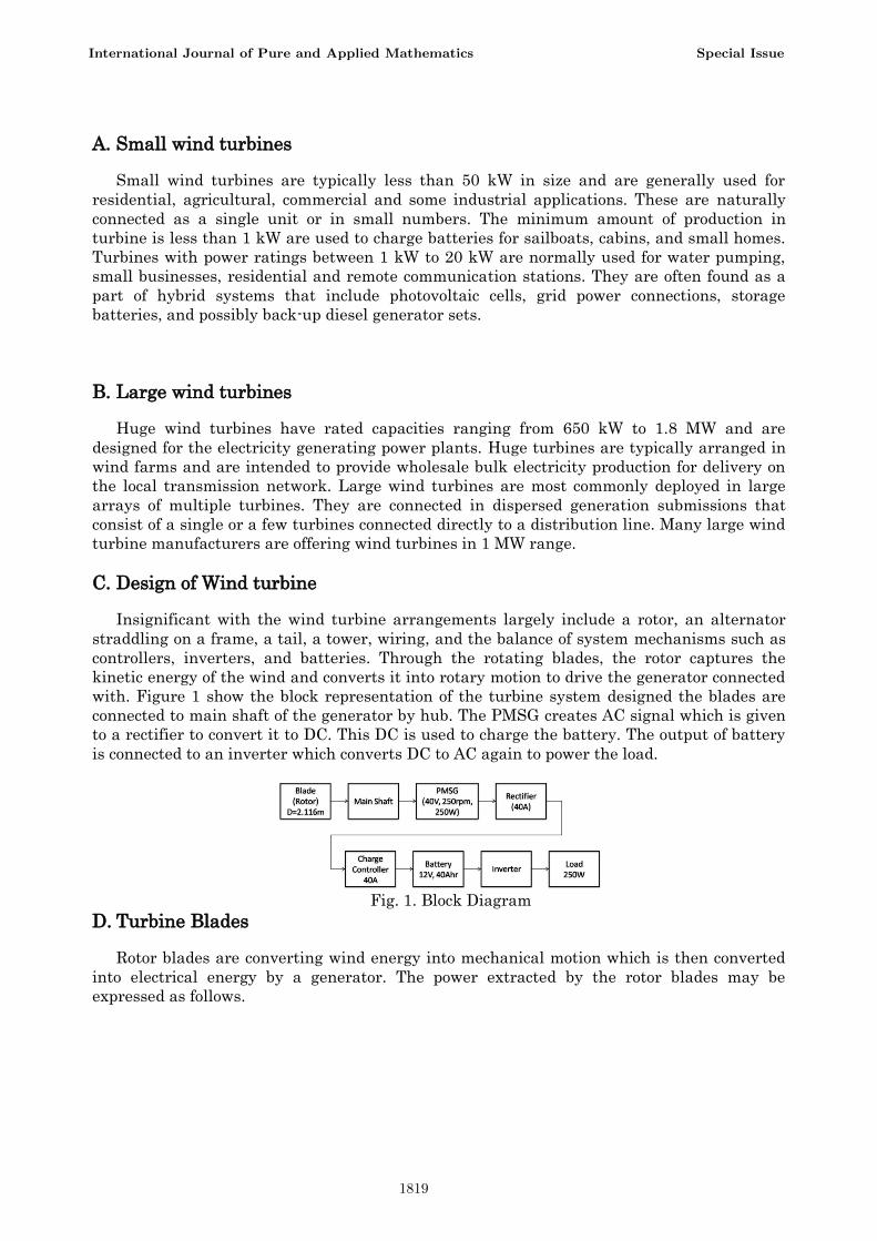
with. Figure 1 show the block representation of the turbine system designed the blades are
connected to main shaft of the generator by hub. The PMSG creates AC signal which is given
to a rectifier to convert it to DC. This DC is used to charge the battery. The output of battery
is connected to an inverter which converts DC to AC again to power the load.
Fig. 1. Block Diagram
D. Turbine Blades
Rotor blades are converting wind energy into mechanical motion which is then converted
into electrical energy by a generator. The power extracted by the rotor blades may be
expressed as follows.
International Journal of Pure and Applied Mathematics Special Issue
1819

PT = 4𝑎 (1 − 𝑎)2 [1
2𝜌𝐴𝑢𝑜
3] (1)
where
a is the perturbation factor
ρ is the density of the air
A is the swept area of the blades and
uo is the speed of the upstream wind
From the Eq. 1 the overall diameter of the rotor blade [3], [11]. So the blade profile NACA-63215 has been chosen whose specification is given in the Table II.
TABLE II BLADE SPECIFICATION
Parameters Specification
No of blades 3 no’s (1m each)
Sweep area 3.5 m2
Material Fiber glass
Design type up wind design
Twisted angle (θ) 18.40
The plan of the individual blades is also a influence affecting the overall routine of the rotor. Since the blades require a fairly smooth airflow to perform, they must be strategically arranged around the axis of rotation so that they cause the minimum turbulence to the airflow of adjacent blades [5], [10]. This is the aim why greatest of the rotors have only two or three blades. The blade design calculations are given below. And the finished blade is shown in the Fig. 2.
International Journal of Pure and Applied Mathematics Special Issue
1820

Fig. 2. Finished Blade
Swept area is the area through which rotor blades of the wind turbine rotates. Swept area for 250W wind turbine may be in the range of 3 – 4 m2. For calculation it is taken as 3.5m2.
Swept Area (πr2) = 3500mm2 Radius of the rotor = 1050mm Radius of the hub =160 mm Length of the blade = r – radius of hub = 1050 – 160 = 890 mm 900 mm
E. Generator One of the maximum critical parts of the wind turbine is Generator. The accountability of the generator is to adapt mechanical energy from the blades into electrical energy. From all the generators that are used in wind turbines PMSG’s had the advantages of being stable and secure through the normal operation. They do not need an additional DC supply for excitation as well [6], [7]. The generator selected for this work is shown in the Fig. 3 whose specifications are given in the Table III. .
Fig. 3. Permanent Magnet Synchronous Generator
International Journal of Pure and Applied Mathematics Special Issue
1821

TABLE III GENERATOR SPECIFICATION
Parameters Specification
Generator type 3phase-PMSG
Power output 300 W
Voltage output 40 V
Pole 24
Gauge 19
F. Vane Wind vane is the one which is used for sensing the wind direction. It consists of a fin attached to a horizontal rod with a counterweight on the other side of the rod as shown in the Fig. 4. The rod is mounted on a vertical spindle at the point of balance. The wind vane is able to rotate freely around in a horizontal plane. As the wind blows from one direction, the wind vane adjusts itself to point the wind direction. The position of the pointer is interpreted by a transducer, which produces an electrical signal relative to a reference position. Normally a potentiometer is used as the transducer.
It is a tail shape arrangement which senses wind direction and communicates with the yaw drive to orient the turbine properly with respect to the wind direction. It helps the blades facing towards the wind. The Vane arrangement is shown in the Fig. 4.
Tower Design
As stated in the Table IV, the tower has been designed with the combination of both lattice and pole. And the erected tower is shown in the Fig. 5.
TABLE IV TOWER SPECIFICATION
Parameters Specification
Tower Type lattice & pole
Total Height 4m
(Lattice- 3m:Pole- 1m)
G. Design of Inverter The function of Inverter is to convert DC power into AC power. A nominal DC voltage of 12 V can
be applied as input to the inverter. Here the inverter output is connected to load directly. By choosing the firing of switches the amount of power conveyed will be varied the total harmonic distortion will be limited..
TABLE V SPECIFICATIONS OF THE INVERTER
Parameters Values
Input voltage minimum (UDC_min ) 11.4V
Input voltage maximum (UDC_min ) 14.6V
Nominal output apparent power (Sout ) 500 VA
Maximum output current (Iout ) 2A (RMS)
Switching frequency (fsw ) 2 kHz
International Journal of Pure and Applied Mathematics Special Issue
1822

The power devices can be switched in a complementary manner (if T1 is ON, T2 is OFF and vice versa).The schematic diagram for the inverter is shown in Fig. 7.
Fig. 7. Circuit Diagram of Inverter Circuit
The inductor connected with the DC source performs two actions. One is to filter out current ripples and another is to boost the voltage in DC section. The selected inductor parameters are given in the Table VI.
TABLE VI INDUCTOR PARAMETER
Parameters Values
Inductance ( L) 120 m H
Maximum current Imax 2 A
Core Type Ferrite
IV. CHARGE CONTROLLER UNIT
Primarily, charge controller in a wind-mill charging system protects batteries from overcharging, just like the solar controller the overcharging leads to electrolyte for boiling which can damage the battery. So the charge controller either separates the turbine power from the battery or diverts it to a dummy load if the battery is fully charged. The load is usually a heating element which burns off excess energy as heat. This heat energy can further be rehabilitated to a useful work. Since deep clearing will also affect the battery, the controller disconnects the load from the system at low wind speed.
All loads are taken directly from the battery. If the battery voltage drops below 11 V, the controller switches the turbine power to charge the battery. If the battery voltage rises to 14 V, the controller switches the turbine power into the dummy load.
Table VII Specifications of the Charge Controller
Conventional systems for charging wind system batteries relied on ON-OFF regulators to limit battery out gabbing during the excess energy production, but resulted in the early battery failures and increased load disconnects. With the PWM technique, the charge controller will reduce the charging
Specifications Ranges
Charge current max. 40A
Load current max. 40A
System voltage 12 V
Self power consumption < 4mA
International Journal of Pure and Applied Mathematics Special Issue
1823
current to prevent gassing and overheating problems of the battery [4], [12]. The benefits of PWM charge controllers are increased charging efficiency, rapid recharging and healthy battery life. Table VII gives the specification of the charge controller.
Monitoring of Wind Turbine Parameters
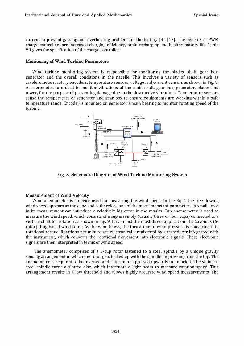
Wind turbine monitoring system is responsible for monitoring the blades, shaft, gear box, generator and the overall conditions in the nacelle. This involves a variety of sensors such as accelerometers, rotary encoders, temperature sensors, voltage and current sensors as shown in Fig. 8. Accelerometers are used to monitor vibrations of the main shaft, gear box, generator, blades and tower, for the purpose of preventing damage due to the destructive vibrations. Temperature sensors sense the temperature of generator and gear box to ensure equipments are working within a safe temperature range. Encoder is mounted on generator’s main bearing to monitor rotating speed of the turbine.
Fig. 8. Schematic Diagram of Wind Turbine Monitoring System
Measurement of Wind Velocity
Wind anemometer is a device used for measuring the wind speed. In the Eq. 1 the free flowing wind speed appears as the cube and is therefore one of the most important parameters. A small error in its measurement can introduce a relatively big error in the results. Cup anemometer is used to measure the wind speed, which consists of a cup assembly (usually three or four cups) connected to a vertical shaft for rotation as shown in Fig. 9. It is in fact the most direct application of a Savonius (S-rotor) drag based wind rotor. As the wind blows, the thrust due to wind pressure is converted into rotational torque. Rotations per minute are electronically registered by a transducer integrated with the instrument, which converts the rotational movement into electronic signals. These electronic signals are then interpreted in terms of wind speed.
The anemometer comprises of a 3-cup rotor fastened to a steel spindle by a unique gravity sensing arrangement in which the rotor gets locked up with the spindle on pressing from the top. The anemometer is required to be inverted and rotor hub is pressed upwards to unlock it. The stainless steel spindle turns a slotted disc, which interrupts a light beam to measure rotation speed. This arrangement results in a low threshold and allows highly accurate wind speed measurements. The
International Journal of Pure and Applied Mathematics Special Issue
1824

internal electronic modules convert the light beam signal into the required analogue or pulse output. The anemometer is mounted on a mast.
Fig. 9. Cup Type Anemometer for Measurement of Wind Speed
Sensing the Wind Direction
The fixed-reference wire-wound potentiometer wind vane is selected for sensing wind direction. Like the wind anemometer, the wind vane has a fixing screw at the base for mounting it on a mast. It also has a gravity sensing fastening arrangement for securing the vane arm assembly on the potentiometer spindle. A notch on the spindle ensures that the vane arm assembly is always mounted in one particular angular position on the spindle. The stainless steel spindle runs in a hard plastic upper bearing and a lower thrust ball bearing and is connected to a potentiometer wiper. The potentiometer output is proportional to the resistance element covered by the wiper of the potentiometer, with a small section of dead band of 3.5 degrees near the ends. The dead band gap is filled with an insulator to provide smooth transition from one terminal to the other.
Fig. 10. VB Form with Interfacing of Various Parameters
Table VIII Power Performance of the Wind Turbine System
Sl. No.
Connected
Load in
Watts
Battery
Voltage
in
Volts(V)
Battery
Discharge
current
in Amps
(A)
Input
Power
(W)
Output
Voltage
in
Volts(V)
Output
Current
in
Amps(A)
Output
Power in
Watts(W)
%
Efficiency
of
Inverter
(η)
1 No Load 12.3 0 0 229 0 0 0
2 100 12.2 10 122 215 0.4 90 73.77
3 160 12.2 14 171 214 0.7 150 87.71
International Journal of Pure and Applied Mathematics Special Issue
1825
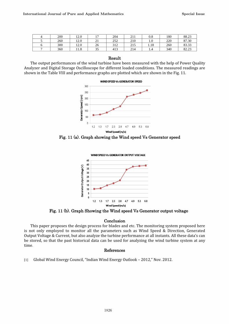
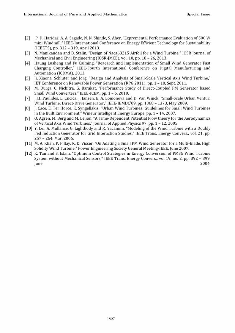
Result The output performances of the wind turbine have been measured with the help of Power Quality
Analyzer and Digital Storage Oscilloscope for different loaded conditions. The measured readings are shown in the Table VIII and performance graphs are plotted which are shown in the Fig. 11.
Fig. 11 (a). Graph showing the Wind speed Vs Generator speed
Fig. 11 (b). Graph Showing the Wind speed Vs Generator output voltage
Conclusion This paper proposes the design process for blades and etc. The monitoring system proposed here
is not only employed to monitor all the parameters such as Wind Speed & Direction, Generated Output Voltage & Current, but also analyze the turbine performance at all instants. All these data’s can be stored, so that the past historical data can be used for analyzing the wind turbine system at any time.
References
[1] Global Wind Energy Council, “Indian Wind Energy Outlook – 2012,” Nov. 2012.
4 200 12.0 17 204 211 0.8 180 88.23
5 260 12.0 21 252 210 1.0 220 87.30
6 300 12.0 26 312 215 1.18 260 83.33
7 360 11.8 35 413 214 1.4 340 82.23
International Journal of Pure and Applied Mathematics Special Issue
1826
[2] P. D. Haridas, A. A. Sagade, N. N. Shinde, S. Aher, “Expremental Performance Evaluation of 500 W mini Windmill,” IEEE-International Conference on Energy Efficient Technology for Sustainability (ICEETS), pp. 312 – 319, April 2013.
[3] N. Manikandan and B. Stalin, “Design of Naca63215 Airfoil for a Wind Turbine,” IOSR Journal of Mechanical and Civil Engineering (IOSR-JMCE), vol. 10, pp. 18 – 26, 2013.
[4] Haung Lusheng and Fu Caiming, “Reaearch and Implementation of Small Wind Generator Fast Charging Controller,” IEEE-Fourth International Conference on Digital Manufacturing and Automation (ICDMA), 2013.
[5] Ji, Xiaona, Schluter and Jorg, “Deaign and Analysis of Small-Scale Vertical Axis Wind Turbine,” IET Conference on Renewable Power Generation (RPG 2011), pp. 1 – 10, Sept. 2011.
[6] M. Durga, C. Nichitra, G. Barakat, “Performance Study of Direct-Coupled PM Generator based Small Wind Converters,” IEEE-ICEM, pp. 1 – 6, 2010.
[7] J.J.H.Paulides, L. Encica, J. Jansen, E. A. Lomonova and D. Van Wijick, “Small-Scale Urban Venturi Wind Turbine: Direct-Drive Generator,” IEEE-IEMDC’09, pp. 1368 – 1373, May 2009.
[8] J. Cace, E. Ter Horce, K. Syngellakis, “Urban Wind Turbines: Guidelines for Small Wind Turbines in the Built Environment,” Wineur Intelligent Energy Europe, pp. 1 – 14, 2007.
[9] O. Agren, M. Berg and M. Leijon, “A Time-Dependent Potential Flow theory for the Aerodynamics of Vertical Axis Wind Turbines,” Journal of Applied Physics 97, pp. 1 – 12, 2005.
[10] Y. Lei, A. Mullance, G. Lightbody and R. Yacamini, “Modeling of the Wind Turbine with a Doubly Fed Induction Generator for Grid Interaction Studies,” IEEE Trans. Energy Convers., vol. 21, pp. 257 – 264, Mar. 2006.
[11] M. A. Khan, P. Pillay, K. D. Visser, “On Adating a Small PM Wind Generator for a Multi-Blade, High Solidity Wind Turbine,” Power Engineering Society General Meeting-IEEE, June 2007.
[12] K. Tan and S. Islam, “Optimum Control Strategies in Energy Conversion of PMSG Wind Turbine System without Mechanical Sensors,” IEEE Trans. Energy Convers., vol 19, no. 2, pp. 392 – 399, June 2004.
International Journal of Pure and Applied Mathematics Special Issue
1827

1828