Embed Size (px)
Citation preview

International Journal of Engineering and Manufacturing Science.
ISSN 2249-3115 Volume 8, Number 1 (2018), pp. 89-100
© Research India Publications
http://www.ripublication.com
Design and Analysis of Renewable Energy Based
Interleaved Flyback Inverter
G.Ganesan @ Subramanian 1, Dr. M.K.Mishra2, S.Latha3 and M.Ramya4
1,3,4Assistant Professor, E.G.S. Pillay Engineering College, Nagapattinam, India. 2 Director – R&D, E.G.S. Pillay Engineering College, Nagapattinam, India.
Emai:[email protected]; [email protected]
Abstract
Photovoltaic (PV) is a method of generating electrical power by converting
solar radiation into direct current electricity using semiconductors that exhibit
the photovoltaic effect. Photovoltaic (PV) power generation has become one
of the main ways to use solar energy. And the renewable energy source based
distributed generation (DG) system are normally interfaced to the grid through
power electronic converters or inverters. An interleaved flyback inverter based
photovoltaic system with an improved control strategy with MATLAB
Simulink is used result is discussed in this paper.
Keywords: Photo Voltaic (PV), Pulse-Width Modulation (PWM), Distributed
Generation DG, Interleaved Flyback Inverter (ILFI)
INTRODUCTION
Generally Photovoltaic (PV) energy has plays the major role in the renewable energy.
The PV technique also grown faster even though the initial cost is high but the solar
energy is available at free of cost by naturally and its efficiency also high. To obtain
the sufficient power the PV system use the PV modules are connected in series or
parallel. By means of mismatch between the modules, shadows from trees or tree
branches, buildings and other things partially cover the PV module so the
conventional PV system having power losses. To overcome this problem photovoltaic
AC module is considered, For the photovoltaic AC module flyback inverter is the best
for the grid connection because it having advantages of less components, simple in
construction and provide the isolation between the PV modules and grid line.

90 G.Ganesan @ Subramanian, Dr. M.K.Mishra, S.Latha and M.Ramya
Interleaved flyback inverter (ILFI) is basically design for to get the maximum power
from the PV module. Normally the conventional flyback inverter having the voltage
spike across the main switch. For reducing the voltage spike across the main switch
the active clamp circuit is used. The clamp circuit is also used to reduce the switching
loss because the main switch is operate with soft switching. By using of the
interleaved technique in the inverter the conduction loss of each switch can me
minimized, reliability, system life is improved, the ripple current is reduced by the
capacitor.
II. SYSTEM STRUCTURE AND ANALYSIS
A. BLOCK DIAGRAM
Fig 1. Block diagram for ILFI

Design and Analysis of Renewable Energy Based Interleaved Flyback Inverter 91
B. CIRCUIT CONFIGURATION AND OPERATION
Fig 2. Interleaved flyback inverter for photovoltaic AC module
Interleaved flyback inverter for photovoltaic AC module consists of the PV module as
input, decoupling capacitor, 1st phase converter, 2nd phase converter, unfolding bridge
and C-L filter. For the Photovoltaic AC system, Maximum Power Point Tracking
(MPPT) is essential to get the peak power from the PV module.
Decoupling capacitor is used to remove the harmonic frequency which distorts the
constant PV voltage and current. Both the flyback converters consist of main
switches, active clamp circuit, Transformer and Diode.
The active clamp circuit is used to reduce the voltage spike across the main switch
which is occurring in resonance between output capacitor and leakage inductance.
Transformer is used to maintaining the isolation between PV module and grid line and
also boost the voltage. Unfolding bridge is used for connection between transformer
and grid line.
C. MODES OF OPERATION
The ILFI having ten operational modes in the switching period, Based on its steady
state operation. Due to simplicity of control here considered only discontinuous
conduction mode (DCM).It having ten modes of operations, Two PWM signals with
180o phase is given by means of this each switch is controlled in interleaved method.
Mode [1]- Mode [5] operated first. Similarly after 180o phase shift, Mode [6]- Mode
[10] is operated. The following modes are shows the steady state operation of ILFI.

92 G.Ganesan @ Subramanian, Dr. M.K.Mishra, S.Latha and M.Ramya
Fig 3. Steady state operations of ILFI
III. ACTIVE CLAMP CONTROL TECHNIQUE
A. Without Active clamp circuit:
When the main switch Sp1 is turned off, the voltage across Sp1 is sum of the input
voltage, feedback voltage and voltage spike which is cause by means of resonance
between the leakage inductance Llk1 and output capacitance Coss of the Sp1. When the
voltage spike of Sp1 increased over the rating then the Sp1 has to fail. For reducing this
voltage spike of the main switch Sp1 the active clamp circuit is used.
B. With Active clamp circuit:
When using the active clamp circuit the leakage energy will be absorbed by the clamp
capacitor Cc1. Hence the voltage spike across the main switch Sp1 can be reduced. So

Design and Analysis of Renewable Energy Based Interleaved Flyback Inverter 93
during the grid period the ILFI operates stable due to the small voltage across the
main switch Sp1 than its rating.
IV. MAXIMUM POWER POINT TRACKING
MPPT charge controller is a maximum power point tracker which is an electronic DC
to DC converter which takes the DC input from the solar panels, changes it to high
frequency AC and converts it back to a different DC current to match with the
batteries.
A. DIFFERENT MPPT ALGORITHM
The different types of algorithms which are used for finding MPPT of the solar panel
are
Conventional Algorithms
Perturb & Observe
Incremental conductance
Constant voltage method
Constant current method
B. PRINCIPLE OF P&O
If the operating current or, in other words, the current drawn from the PV array is
perturbed in a given direction and if the power drawn from the PV array increases, the
operating point becomes closer to the MPP and, thus, the operating current should be
further perturbed in the same direction.
If the current is perturbed and this results in a decrease in the power drawn from the
PV array, this means that the point of operation is moving away from the MPP and
therefore, the perturbation of the operating current should be reversed.
Fig 4.shows the flow chart of the perturb and observe MPPT algorithm.

94 G.Ganesan @ Subramanian, Dr. M.K.Mishra, S.Latha and M.Ramya
Fig 4. Flow chart of the P&O technique
Table I: Design parameter of ILFI
PARAMETER VALUE UNIT
Grid Frequency
fgrid
50 Hz
Input Capacitance
Cin
11 mF
DC link Capacitance
Co
136 nF
Leakage Inductance Llk1,Llk2 0.21 µH
Transformer Turns Ratio 1:6 -
Magnetizing Inductance
Lm1,Lm2
8.28 µH
Filter Capacitance
Cf
25 µF
Filter Inductance
Lf
3 mH
Design and Analysis of Renewable Energy Based Interleaved Flyback Inverter 95
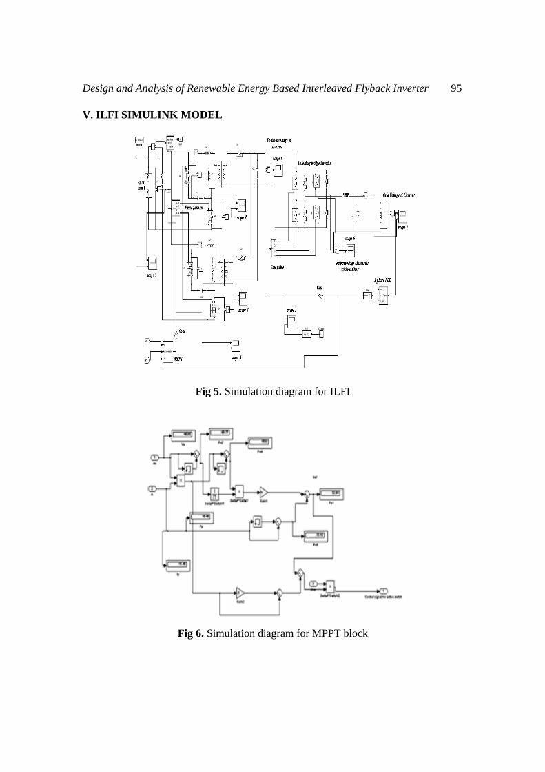
V. ILFI SIMULINK MODEL
Fig 5. Simulation diagram for ILFI
Fig 6. Simulation diagram for MPPT block

96 G.Ganesan @ Subramanian, Dr. M.K.Mishra, S.Latha and M.Ramya
VI. SIMULATION RESULTS
The simulation results are produced with MATLAB 2009b. The result shows the
waveforms for voltage and current across PV panel. Also, the gate pulses of each
switches, voltage across the main switch and active clamp switch, DC input voltage
for the inverter, inverter output voltage without filter and grid voltage, grid current.
Fig 7. voltage and current across PV panel
Fig 8. Gate pulses of each switches

Design and Analysis of Renewable Energy Based Interleaved Flyback Inverter 97
Fig 9. Voltage across switch Sa1, Sp1
Fig 10. Voltage across switch Sa2, Sp2
Fig 11. DC input voltage for the inverter
98 G.Ganesan @ Subramanian, Dr. M.K.Mishra, S.Latha and M.Ramya
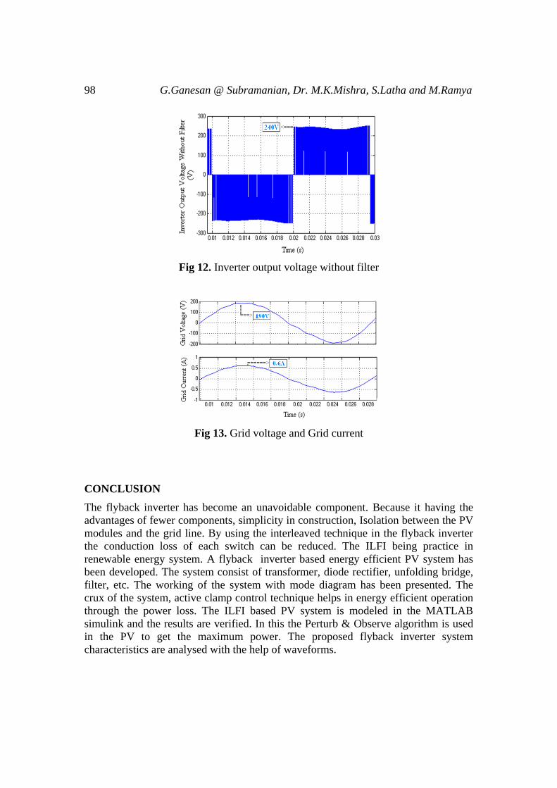
Fig 12. Inverter output voltage without filter
Fig 13. Grid voltage and Grid current
CONCLUSION
The flyback inverter has become an unavoidable component. Because it having the
advantages of fewer components, simplicity in construction, Isolation between the PV
modules and the grid line. By using the interleaved technique in the flyback inverter
the conduction loss of each switch can be reduced. The ILFI being practice in
renewable energy system. A flyback inverter based energy efficient PV system has
been developed. The system consist of transformer, diode rectifier, unfolding bridge,
filter, etc. The working of the system with mode diagram has been presented. The
crux of the system, active clamp control technique helps in energy efficient operation
through the power loss. The ILFI based PV system is modeled in the MATLAB
simulink and the results are verified. In this the Perturb & Observe algorithm is used
in the PV to get the maximum power. The proposed flyback inverter system
characteristics are analysed with the help of waveforms.

Design and Analysis of Renewable Energy Based Interleaved Flyback Inverter 99
REFERENCES
[1] Bolognani S., Peretti L., and Zigliotto M., (2011) “Online MTPA control
strategy for DTC synchronous-reluctance-motor drives,” IEEE Trans. Power
Electron., vol. 26, no. 1, pp. 20–28.
[2] Dwari S., and Parsa L., (2011) “An efficient high-step-up interleaved DC–
Converter with a common active clamp,” IEEE Trans. Power Electron.,vol.
26, no. 1, pp. 66–78.
[3] Gao M., Chen M., Mo Q., Qian Z., and Luo Y., (2011) “Research on output
current of interleaved-flyback in boundary conduction mode for photovoltaic
ac module application,” in Proc. IEEE. Energy Convers. Congr. Expo., pp.
770–775.
[4] Hsia T.H., Tsai H.Y., Chen D., Lee M., and Huang C.S., (2011) “Interleaved
active-clamping converter with ZVS/ZCS features,” IEEE Trans. Power
Electron., vol. 26, no. 1, pp. 29–37.
[5] Kasa N., Iida T., and Chen L., (2005) “Flyback inverter controlled by sensor
less current MPPT for photovoltaic power system,” IEEE Trans. Ind.
Electron., vol. 52, no. 4, pp. 1145–1152.
[6] Kim Y.H., Kim J.G., Ji Y.H., Won C.Y., and Lee T.W., (2011) “A new
control strategy of active clamped flyback inverter for a photovoltaic ac
module system,” in Proc. 8th Int. Conf. Power Electron., pp. 1880–1885.
[7] Kim Y.H., Kim J.G., Won C.Y., Jung Y.C., and Lee T.W., (2011) “Soft
switching interleaved active clamp flyback inverter for a photovoltaic ac
module system,” in Proc.14th Eur. Conf. Power Electron., pp. 1–9.
[8] Kjaer S.B., Pedersen J.K., and Blaabjerg F., (2005) “A review of single-phase
grid-connected inverters for photovoltaic modules,” IEEE Trans. Ind. Appl.,
vol. 41, no. 5, pp. 1292–1306.
[9] Kyritsis A.C., Tatakis E. C., and Papanikolaou N. P., (2008) “Optimum design
of the current-source flyback inverter for decentralized grid-connected
photovoltaic systems,” IEEE Trans. Energy Convers., vol. 23, no. 1, pp. 281–
293.
[10] Mo Q., Chen M., Zhang Z., Zhang Y., and Qian Z., (2012) “Digitally
controlled active clamp interleaved flyback converters for improving
efficiency in photovoltaic grid-connected micro-inverter,” in Proc.IEEE 27th
Annu. Power Electron. Conf. Expo.,pp. 555–562.
[11] Nanakos A.C., Tatakis E. C., and Papanikolaou N. P., (2012) “A weighted
efficiency oriented design methodology of flyback inverter for ac photovoltaic
modules,” IEEE Trans. Power Electron., vol. 27, no. 7, p. 3221–3233.
[12] Ryu D.K., Kim Y.H., Kim J.G., Won C.Y., and Jung Y.C., (2011)
“Interleaved active clamp flyback inverter using a synchronous rectifier for a

100 G.Ganesan @ Subramanian, Dr. M.K.Mishra, S.Latha and M.Ramya
photovoltaic ac module system,” in Proc. 8th Int. Conf. IEEE Power Electron.
ECCE Asia, pp. 2631–2636.
[13] Shimizu K.,Wada T., and Nakamura N., (2006) “Flyback-type single-phase
utility interactive inverter with power pulsation decoupling on the DC input
for an AC photovoltaic module system,” IEEE Trans. Power Electron., vol.
21, no. 5, pp. 1264–1272.
[14] Xue Y., Chang L., Kjaer S. B., Bordonau J., and Shimizu T., (2004)
“Topologies of single-phase inverters for small distributed power generators:
A overview,” IEEE Trans. Power Electron., vol. 19, no. 5, pp. 1305–1314.
[15] Zhang J., Huang X., Wu X., and Qian Z., (2010) “A high efficiency flyback
converter with new active clamp technique,” IEEE Trans. Power Electron.,
vol. 25, no. 7, p. 1775–1785.


![[XLS]services.iriskf.orgservices.iriskf.org/FCKeditor/_samples/asp/excel/Niraj... · Web viewrspl_hub@rediffmail.com vwdip.bandyopadhyay@rediffmail.com nhemdev@indiatimes.com bajaj@hotpop.com](https://img.pdfslide.us/doc/110x75/5ab070417f8b9a6b308e7f75/xls-viewrsplhubrediffmailcom-vwdipbandyopadhyayrediffmailcom-nhemdevindiatimescom.jpg)