Embed Size (px)
Citation preview

Design and Analysis of a Lightweight Crankshaft for a Racing Motorcycle Engine
Naji Zuhdi, PETRONASPhil Carden, Ricardo UKDavid Bell, Ricardo UK

2 2007- 01- 0265
Contents
IntroductionDesign overviewEngine balanceMain bearing analysisTorsional vibrationStress analysisConclusions

3 2007- 01- 0265
IntroductionWorld Superbike championship• Petronas designed engine when rules allowed 900cc I3 to
compete with 750cc I4• Rule changes meant that 900cc I3 must race 1000cc I4
Main engine development target was to maximise power• Baseline engine had rev limit of 14000 rpm but changes to
valve train enabled 16000 rpm engine speed• Piston and rod were also redesigned to enable operation at
higher speed• This presentation covers design and analysis of crankshaft

4 2007- 01- 0265
Crankshaft design objectivesMain objectives• Reduce crankshaft mass• Reduce rotating inertia• Reduce friction• Reduce windage• Maintain adequate
crankshaft strength• Maintain adequate bearing
durability• Maintain acceptable engine
balance

5 2007- 01- 0265
Crankshaft design overview• Fully machined crank• Integral drive gear • Double vacuum remelted
steel 31CrMoV9• Gas nitrided to 800Hv to
depth of 0.3 mm• Polished bearing journal
surfaces• Full circumferential grooves in
main bearings• Big end bearings supplied
from main bearings via drillings

6 2007- 01- 0265
Crankshaft Design Iterations
Baseline Design
Intermediate Design
Final Design
• Pictures show the design evolution of the crankshaft
• The drive gear was moved from web 3 to web 5 to avoid transmitting power through the balancer shaft
• Piston and rod were lightened during the project
Component Baseline Final Piston assembly mass (kg) 0.292 0.249Connecting rod mass (kg) 0.278 0.245

7 2007- 01- 0265
Reducing Mass and Rotating Inertia• Smaller counterweights used for final
design as engine was no longer fully balanced (see later section)
• Reduce the mass of ‘upper’ portion of the crankshaft
• Drill through the crank pin • Use heavy metal inserts in
counterweights• 30% mass reduction• 35% inertia reduction
Baseline
Final

8 2007- 01- 0265
Minimising Friction Losses• Windage loss reduction
• Thinner webs with chamfered edges• Shrouded balance shaft
• Bearing friction loss reduction• Journal diameters were not changed
due to cost and lead time implication

9 2007- 01- 0265
Increasing Strength• Final design had ‘piston guided rod’• This eliminated the need for thrust faces
on big end journals• Thus permitting use of a large fillet radius
in the critical area of crankshaft overlap region
Baseline Final
10 2007- 01- 0265
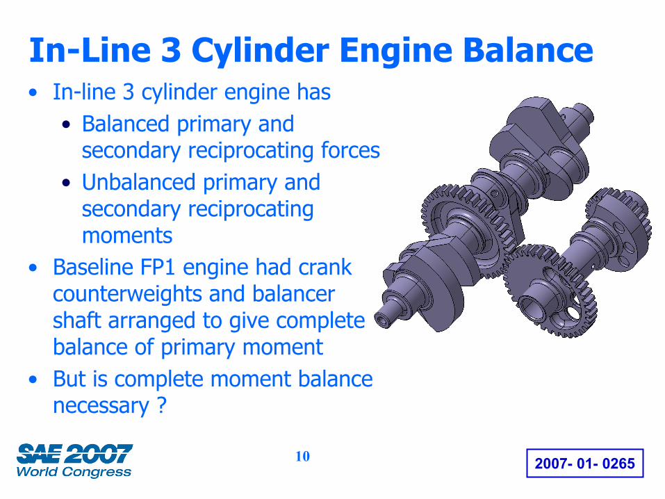
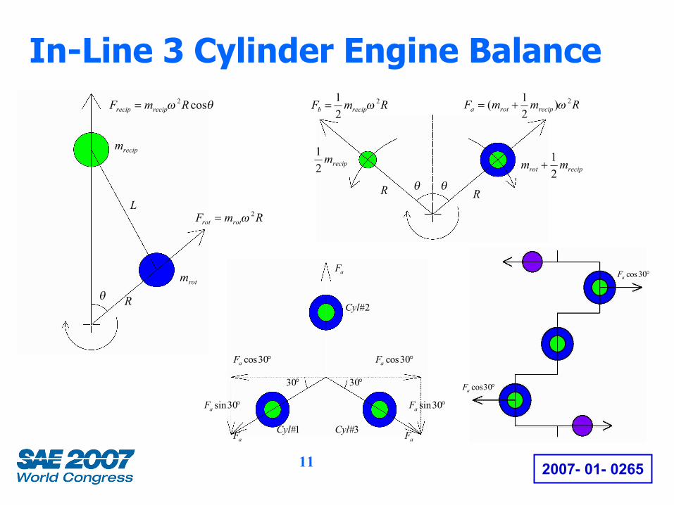
In-Line 3 Cylinder Engine Balance• In-line 3 cylinder engine has
• Balanced primary and secondary reciprocating forces
• Unbalanced primary and secondary reciprocating moments
• Baseline FP1 engine had crank counterweights and balancer shaft arranged to give complete balance of primary moment
• But is complete moment balance necessary ?
11 2007- 01- 0265
In-Line 3 Cylinder Engine BalanceRmF recipb
2
21
ω=
recipm21
reciprot mm21
+
Rθ
RmmF reciprota2)
21( ω+=
R θ
θω cos2RmF reciprecip =
RmF rotrot2ω=
recipm
rotm
R
L
θ
°30cosaF
1#Cyl
2#Cyl
3#Cyl
aF
aFaF
°30cosaF
°30°30
°30sinaF°30sinaF
°30cosaF
°30cosaF

12 2007- 01- 0265
Crank/Balancer Design Iterations• Removing the counterweights on
the balance shaft was tried• Level of vibration was acceptable to
riders but a frame failure occurred• A compromise was adopted for the
final design
Baseline Design Experimental
DesignFinal
Design
Component BaselineDesign
Final Design
Fa force balance factor 50% 30%Primary forces 100% 100%Primary moment, Ma 100% 90%Primary moment, Mb 100% 60%

13 2007- 01- 0265
Residual out-of-balance moments• Numerical values of residual out-of-
balance moments are shown• For engine with no counterweights• For baseline design• For final design
Parameter No c/w Baseline FinalPrimary shaking moment
– pitch at 14000 rpm (Nm)9158 0 1031
Primary shaking moment – pitch at 16000 rpm (Nm)
- - 1345
Secondary shaking moment – pitch at 14000 rpm (Nm)
803 803 683
Secondary shaking moment – pitch at 16000 rpm (Nm)
- - 892
Primary shaking moment – yaw at 14000 rpm (Nm)
5816 0 215
Primary shaking moment – yaw at 16000 rpm (Nm)
- - 281

14 2007- 01- 0265
Main bearing analysis• ENGDYN bearing analysis shows
• Reduced peak specific load at worst case speed (peak torque)
• Slight reduction in minimum oil film thickness at high speed
• Slight increase in hydrodynamic power loss at 14000 rpm
Parameter Baseline FinalMaximum peak
specific main bearing load (N/mm2)
56.3 @ Main No.412000 rpm
54.9 @ Main No.412000 rpm
Minimum oil film thickness (µm)
0.59 @ Main No.414000 rpm
0.53 @ Main No.216000 rpm
Maximum predicted oil temperature (°C)
159.3 @ 14000 rpm
160.2 @ 14000 rpm165.5 @ 16000 rpm
Total power loss at all main bearings (kW)
3.022 @ 14000 rpm
3.144 @ 14000 rpm4.001 @ 16000 rpm
15 2007- 01- 0265
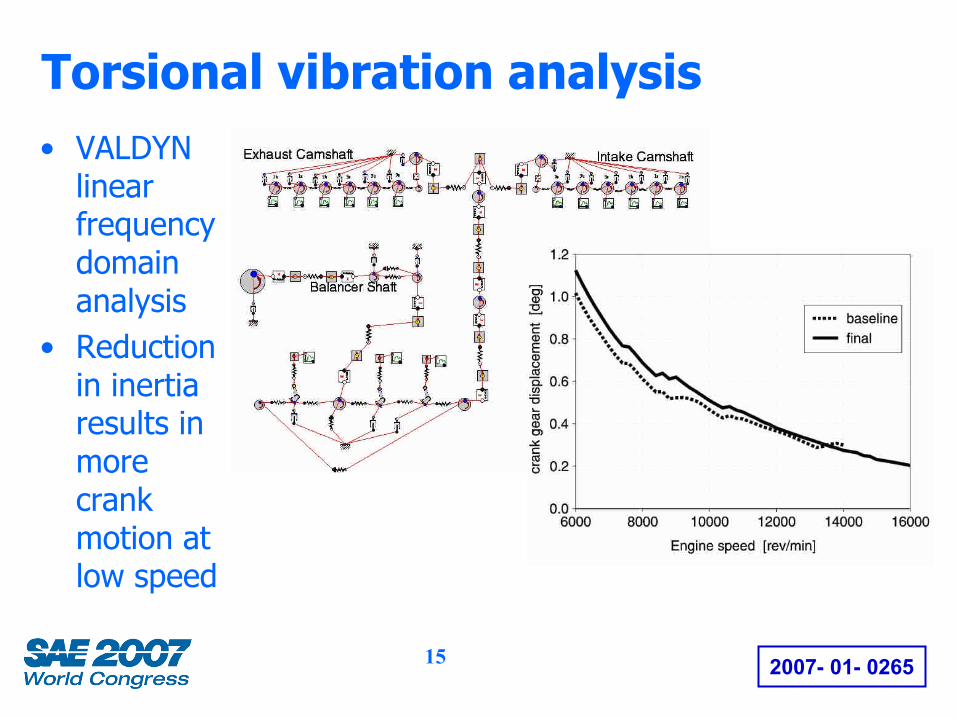
Torsional vibration analysis• VALDYN
linear frequency domain analysis
• Reduction in inertia results in more crank motion at low speed

16 2007- 01- 0265
Torsional vibration analysis
• ENGDYN 3D crankshaft dynamics analysis shows significant increase in crankshaft twist for final design
• Baseline crank natural frequency of 1317 Hz
• Final crank natural frequency of 971 Hz
4.5 order peak

17 2007- 01- 0265
Stress analysis• Finite element analysis was
performed on the baseline and final crankshafts
• ENGDYN used to• Calculate boundary conditions• Combine FE models• Solve equations of motion• Calculate combined stresses at
5 degree intervals for each engine speed
• Calculate Goodman safety factors at fillets and oil holes

18 2007- 01- 0265
Stress analysis• UTS 1050 N/mm2
• Yield strength 900 N/mm2
• Fatigue strength estimated accounting for influence of nitriding and size effect• At pin fillets 745 N/mm2
• At main fillets 747 N/mm2
• At pin oil holes 745 N/mm2
• Baseline results indicate that lowest safety factor occurred at crank pin fillet on web No.1

19 2007- 01- 0265
Stress analysis• Results compared for pin fillet
at web No. 1• Lower safety factor for
intermediate design• Lowest value for final design at
4.5 order resonance at ~13500 rpm
• Intermediate crank design did fail at pin fillet on Web No.1

20 2007- 01- 0265
Practical experience• Track testing was performed with engines having various
degrees of unbalance• Riders preferred low inertia of final design• Riders were prepared to tolerate increased vibration
• Crankshaft was very durable• No failures of baseline or final design on test or during
racing• Crankshaft was usually replaced after 4 million cycles
• some baseline cranks experienced 7 million cycles• some final cranks experienced 6 million cycles
• No significant wear of main bearings

21 2007- 01- 0265
ConclusionsThe final crankshaft design• had exceptional durability even when rev limiter was
set to 16000 rpm despite considerable increase in twist due to torsional vibration
• had partially balanced primary reciprocating moment• was guided by analysis using Ricardo Software

22 2007- 01- 0265
Thank you for your attention
Any questions ?