Embed Size (px)
Citation preview
7/23/2019 Design Analysis of Word Length Effects in Interpolator Design
http://slidepdf.com/reader/full/design-analysis-of-word-length-effects-in-interpolator-design 1/5
International Journal of Advanced Engineering Research and Technology (IJAERT), ISSN: 2348 –8190
ICRTIET-2014 Conference Proceeding, 30th
-31st
August 2014
Divya Jyoti College of Engineering & Technology, Modinagar, Ghaziabad (U.P.), India
Design Analysis of Word Length Effects in Interpolator Design
1Ankita Mahajan,
2Rajesh Mehra
1ME Scholar &
2Associate Professor
Department of Electronics & Communication Engineering National Institute of Technical Teachers’ Training & Research
Chandigarh, UT, India
ABSTRACT Digital filters are implemented using finite word lengthsfor input, output and the filter coefficients. Errors arecaused by the use of finite word length such as noisegeneration in analog-to-digital conversion, coefficient
quantization errors etc. In this paper FIR interpolator isdesigned and simulated using different word lengths
with equiripple technique. Three different precisions areused for input, output and coefficients. The performanceof interpolator with different precisions has beenanalyzed and compared with each other. It can beobserved from the stimulated results that the output
response of designed interpolator becomes closer to thedesired response by increasing the precision bits.
Key Words: Equiripple, FIR Interpolator, Word length
I. INTRODUCTION
Signals play a major role in our life. A signal can be afunction of time, distance, position, temperature,
pressure etc. By a signal we mean any variable thatcarries some kind of information for example:-
In an electrical system the associated signals are electriccurrent and voltage. In a mechanical system the
associated signals may be force, speed, torque etc. Indaily life we encounter signals such as speech, music,
picture and video.
Digital signal processing is concerned with the digitalrepresentation of signals and the use of digital processorsto analyze, modify, or extract information from signals.
Most signals are analog in nature often meaning thatthey vary continually with time. The signals used in
most popular forms of DSP are derived from analogsignals which have been sampled at regular intervals andconverted into a digital form.
The specific reason for processing a digital signal may
be to remove interference or noise from the signal, toobtain the spectrum of the data, or to transform the
signal into a more suitable form [1]. Digital signal processing provides advantages such as:- guaranteed
accuracy, perfect reproducibility, no drift in performance, greater flexibility, superior performanceDSP is also suited for low frequency signals.
Application areas
Application areas include the following: Image
processing, Instrumentation/Control, Speech/AudioMilitary, Telecommunication, Biomedical, Consumer
applications. Some of the k ey DSP operations are DSPoperations require only simple arithmetic operations ofmultiply, add/subtract, and shift to carry out. The basic
DSP operations are:- Convolution, Correlation, FilteringTransformation, Modulation.
II. MULTIRATE SYSTEMS
One of the major function of DSP is filtering . Filters are
networks that change the wave shape, amplitude-frequency or phase characteristics of a signal in a desiredmanner. The main role of filter is to improve the qualityof signal and to extract the information from signalsDigital filters are classified as finite duration impulse
response filter i.e. FIR and infinite duration impulseresponse filter i.e. IFIR. In this paper we have done the
design analysis based on FIR filter. So a FIR filter is afilter whose impulse response sequence is of finiteduration which means it has a finite number of non-zero
terms [2]. FIR filter depends only on the present and pasinput samples. FIR filter has following advantages:- theyhave linear phase, they are stable, they can be realized
efficiently in hardware.
FIR filter coefficients can be calculated using thewindow method. But the window method does notcorrespond to any known form of optimization. In fact itcan be shown that the window method is not optimal -
by which we mean it does not produce the lowes possible number of filter coefficients that just meets therequirement. Remez Exchange algorithm is something
7/23/2019 Design Analysis of Word Length Effects in Interpolator Design
http://slidepdf.com/reader/full/design-analysis-of-word-length-effects-in-interpolator-design 2/5
International Journal of Advanced Engineering Research and Technology (IJAERT), ISSN: 2348 –8190
ICRTIET-2014 Conference Proceeding, 30th
-31st
August 2014
Divya Jyoti College of Engineering & Technology, Modinagar, Ghaziabad (U.P.), India
clever. It uses a mathematical optimization method. The
Remez/Parks McLellan method produces a filter which just meets the specification without over performing.
Many of the window method designs actually perform better as you move further away from the pass band, thisis wasted performance, and means they are using more
filter coefficients than they need. Similarly, many of thewindow method designs actually perform better than the
specification within the pass band: this is also wasted performance, and means they are using more filtercoefficients than they need. The Remez/Parks McLellan
method performs just as well as the specification but no better: one might say it produces the worst possibledesign that just meets the specification at the lowest
possible cost - almost a definition of practicalengineering. So Remez/Parks McLellan designs have
equal ripple - up to the specification but no more - in both pass band and stop band. This is why they are often
called equiripple designs. The equiripple design produces the most efficient filters - that is, filters that
just meet the specification with the least number ofcoefficients.
Need of multirate processing
The increasing need in modern digital system to processdata at more than one sampling rate has led to thedevelopment of multirate processing [1]. The two
primary operations in multirate processing aredecimation and interpolation. Decimation reduces thesampling rate, thus compressing the data and retainingonly the desired information. For example, if 16-bitcompact disc audio (sampled at 44,100 Hz) is decimated
to 22,050 Hz, the audio is said to be decimated by afactor of 2 [3]. These are also required in applicationswhere the storage size has to be reduced. Decimator can
be called as anti-aliasing filter. Interpolation increasesthe sampling rate. Example is where high precision
signals are required. This can also be called as anti-imaging filter. Advantages of multirate processing aremany, like high quality data acquisition and storagesystem are increasingly taking its advantage in order toavoid the use of expensive anti-aliasing analog filters
and to handle efficiently signals of different bandwidthwhich require different sampling frequencies.
Multirate processing is basically an efficient technique
for changing the sampling frequency of a signal digitally[1]. The processes of decimation and interpolation arethe fundamental operations in multirate signal
processing, and they allow the sampling frequency to bedecreased or increased without significant undesirable
effects of errors such as quantization and aliasing. In this
paper FIR filter has been used, as performance of amultirate system depends critically on the type and
quality of the filter used. So selection of FIR filter isdone on the basis of its above mentioned advantagesAlso it is required that anti-imaging filter must remove
all but the useful information by bandlimiting themodified data to Fs/2 or less. Although the highest valid
frequency after raising the rate to LFs is LFs/2, accordingto the sampling theorem, it is necessary to bandlimit toFs/2 as this is the highest valid frequency in x(n). The
overall filter requirements for interpolation are:
Pass band : 0≤ f ≤ f P Stop band : FS/2≤ f≤ LFS/2 Pass band deviation: ρP Stop band deviation: ρS [1]
Where f p< Fs/2 a gain of L is necessary in the pass band
to compensate for the amplitude reduction by theinterpolation process.
We know that digital filters are implemented using finiteword lengths for both the data and the filter coefficients.
The main errors caused by the use of finite word lengthare as follows: Noise generated in the analog-to-digita
conversion, resulting from representing the samples ofthe input data by only a few bits. Coefficientquantization errors, caused by representing the filter
coefficients by a finite number of bits. In this paper wordlength effect is considered using fixed point arithmeticHere we consider only filters where both the coefficientsand data samples are given using a fixed pointrepresentation. In this case each data sample is
represented by a sign bit and b decimal bits and it isrequired that inside the filter all the data samples arewithin the range [-1, 1]. For the coefficients someinteger bits are sometimes required. Fixed-pointconversion and word length optimization has a long
history of research. In a fixed-point representationinteger bits are related to the dynamic range of a signaland fractional bits are related to precision. Fordetermining the optimal number of both integer andfractional bits, analytical or simulation-based methods
have been introduced.
Some published approaches to the word lengthoptimization problem use an analytic approach to scaling
and/or error estimation [4]-[6], some use simulation [78], and some use a hybrid of the two [9]. In this papereffect of word length is analyzed by varying the input-
output word length and coefficient length. By varyingthe word length it is found that there is a reduction in the
7/23/2019 Design Analysis of Word Length Effects in Interpolator Design
http://slidepdf.com/reader/full/design-analysis-of-word-length-effects-in-interpolator-design 3/5
International Journal of Advanced Engineering Research and Technology (IJAERT), ISSN: 2348 –8190
ICRTIET-2014 Conference Proceeding, 30th
-31st
August 2014
Divya Jyoti College of Engineering & Technology, Modinagar, Ghaziabad (U.P.), India
noise as the word length increases. Also filter order is
taken into consideration so that the hardwareimplementation of the filter is not hindered while
increasing the word length. As order of the filter plays avery important role in the cost efficiency of the filter.
III. INTERPOLATOR SIMULATIONS
Let us take the FIR equiripple filter of minimum order
and then interpolate by a factor of 2. Now analyze theword length effect on this filter. The analysis will bedone through Matlab.
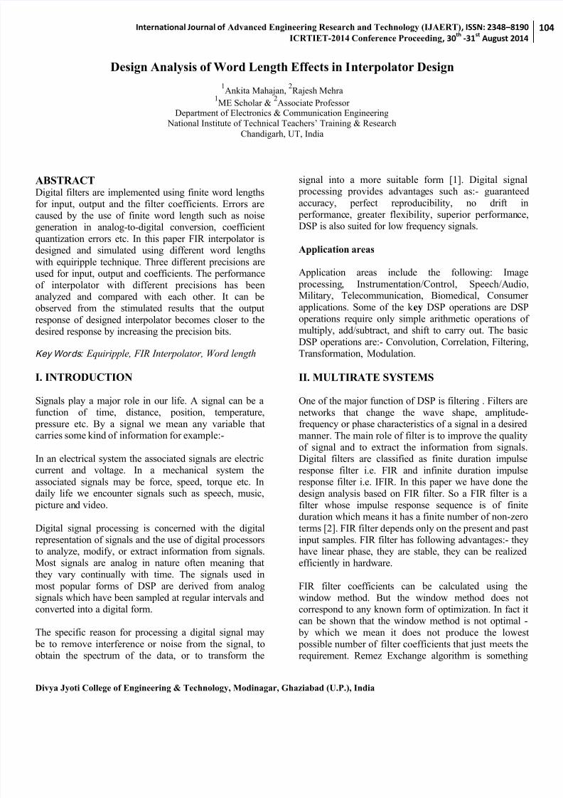
Now for word length 8 the following response is shown
through Matlab simulation.
Fig. 1 FIR Interpolator response when word length =8
This shows that the response is not similar to the originalsignal and this can be treated as quantized noise. The
expected response is much far away from the originalresponse.
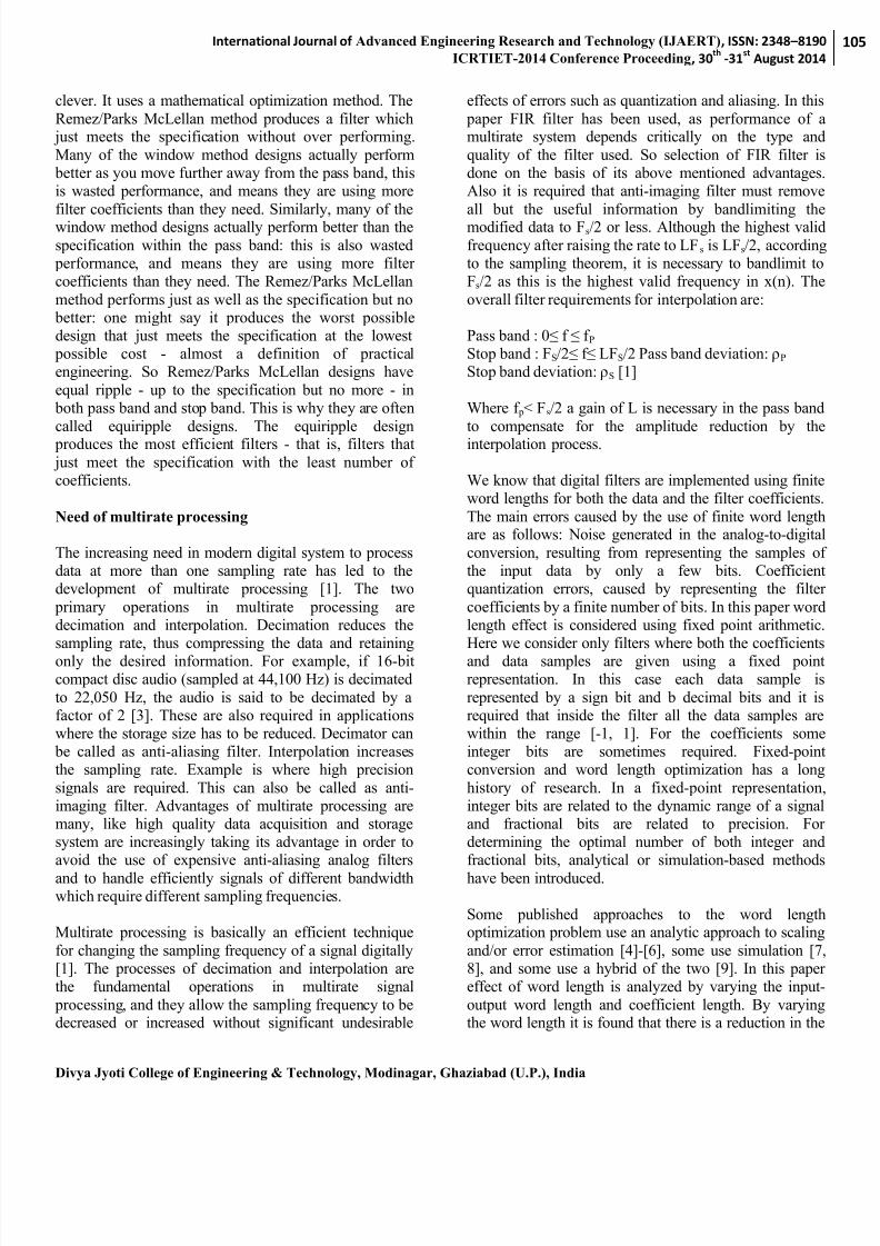
Now again analyzing on word length of 16 we get thefollowing result
Fig. 2 FIR Interpolator response when word length=16
This shows that on increasing the word length theresponse is getting closer to the original signal.
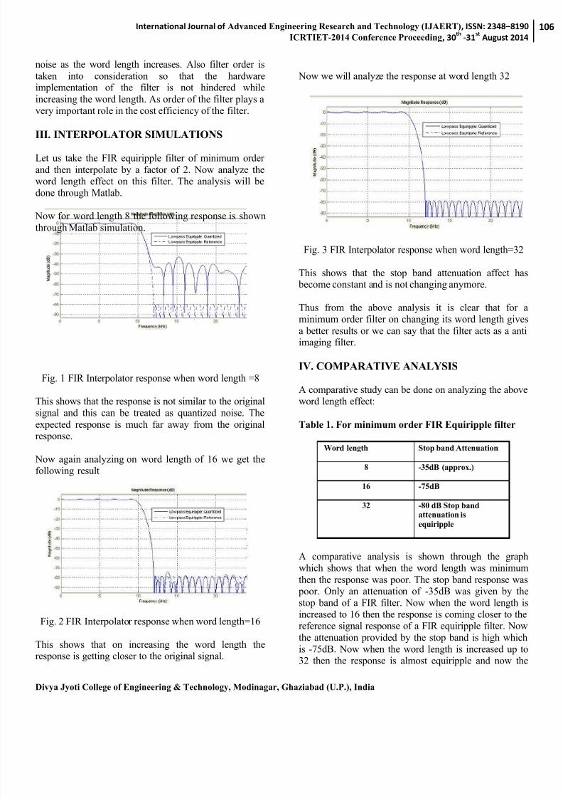
Now we will analyze the response at word length 32
Fig. 3 FIR Interpolator response when word length=32
This shows that the stop band attenuation affect has become constant and is not changing anymore.
Thus from the above analysis it is clear that for aminimum order filter on changing its word length gives
a better results or we can say that the filter acts as a antiimaging filter.
IV. COMPARATIVE ANALYSIS
A comparative study can be done on analyzing the aboveword length effect:
Table 1. For minimum order FIR Equiripple filter
Word length Stop band Attenuation
8 -35dB (approx.)
16 -75dB
32 -80 dB Stop band attenuation is equiripple
A comparative analysis is shown through the graphwhich shows that when the word length was minimum
then the response was poor. The stop band response was poor. Only an attenuation of -35dB was given by thestop band of a FIR filter. Now when the word length isincreased to 16 then the response is coming closer to thereference signal response of a FIR equiripple filter. Now
the attenuation provided by the stop band is high whichis -75dB. Now when the word length is increased up to32 then the response is almost equiripple and now the
7/23/2019 Design Analysis of Word Length Effects in Interpolator Design
http://slidepdf.com/reader/full/design-analysis-of-word-length-effects-in-interpolator-design 4/5
International Journal of Advanced Engineering Research and Technology (IJAERT), ISSN: 2348 –8190
ICRTIET-2014 Conference Proceeding, 30th
-31st
August 2014
Divya Jyoti College of Engineering & Technology, Modinagar, Ghaziabad (U.P.), India
stop band completely attenuates the noise and hence the
performance of the filter smoothens up.
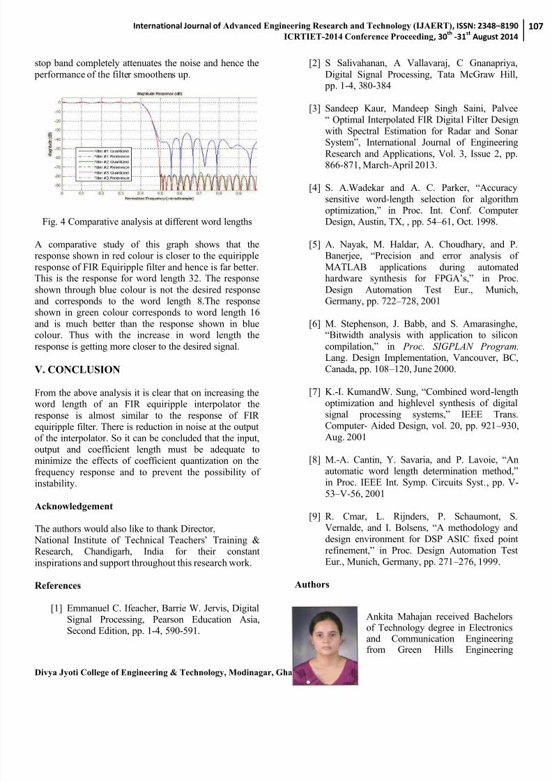
Fig. 4 Comparative analysis at different word lengths
A comparative study of this graph shows that theresponse shown in red colour is closer to the equiripple
response of FIR Equiripple filter and hence is far better.This is the response for word length 32. The response
shown through blue colour is not the desired responseand corresponds to the word length 8.The responseshown in green colour corresponds to word length 16
and is much better than the response shown in bluecolour. Thus with the increase in word length the
response is getting more closer to the desired signal.
V. CONCLUSION
From the above analysis it is clear that on increasing theword length of an FIR equiripple interpolator the
response is almost similar to the response of FIRequiripple filter. There is reduction in noise at the outputof the interpolator. So it can be concluded that the input,output and coefficient length must be adequate tominimize the effects of coefficient quantization on the
frequency response and to prevent the possibility ofinstability.
Acknowledgement
The authors would also like to thank Director, National Institute of Technical Teachers’ Training & Research, Chandigarh, India for their constant
inspirations and support throughout this research work.
References
[1] Emmanuel C. Ifeacher, Barrie W. Jervis, DigitalSignal Processing, Pearson Education Asia,Second Edition, pp. 1-4, 590-591.
[2] S Salivahanan, A Vallavaraj, C Gnanapriya
Digital Signal Processing, Tata McGraw Hill pp. 1-4, 380-384
[3] Sandeep Kaur, Mandeep Singh Saini, Palvee“ Optimal Interpolated FIR Digital Filter Design
with Spectral Estimation for Radar and SonarSystem”, International Journal of Engineering
Research and Applications, Vol. 3, Issue 2, pp866-871, March-April 2013.
[4] S. A.Wadekar and A. C. Parker, “Accuracysensitive word-length selection for algorithmoptimization,” in Proc. Int. Conf. ComputerDesign, Austin, TX, , pp. 54 – 61, Oct. 1998.
[5] A. Nayak, M. Haldar, A. Choudhary, and PBanerjee, “Precision and error analysis of
MATLAB applications during automatedhardware synthesis for FPGA’s,” in Proc
Design Automation Test Eur., MunichGermany, pp. 722 – 728, 2001
[6] M. Stephenson, J. Babb, and S. Amarasinghe“Bitwidth analysis with application to silicon
compilation,” in Proc. SIGPLAN ProgramLang. Design Implementation, Vancouver, BCCanada, pp. 108 – 120, June 2000.
[7] K.-I. KumandW. Sung, “Combined word-lengthoptimization and highlevel synthesis of digitalsignal processing systems,” IEEE TransComputer- Aided Design, vol. 20, pp. 921 – 930
Aug. 2001
[8]
M.-A. Cantin, Y. Savaria, and P. Lavoie, “Anautomatic word length determination method,”in Proc. IEEE Int. Symp. Circuits Syst., pp. V
53 – V-56, 2001
[9]
R. Cmar, L. Rijnders, P. Schaumont, SVernalde, and I. Bolsens, “A methodology anddesign environment for DSP ASIC fixed point
refinement,” in Proc. Design Automation TestEur ., Munich, Germany, pp. 271 – 276, 1999.
Authors
Ankita Mahajan received Bachelorsof Technology degree in Electronicsand Communication Engineeringfrom Green Hills Engineering
7/23/2019 Design Analysis of Word Length Effects in Interpolator Design
http://slidepdf.com/reader/full/design-analysis-of-word-length-effects-in-interpolator-design 5/5
International Journal of Advanced Engineering Research and Technology (IJAERT), ISSN: 2348 –8190
ICRTIET-2014 Conference Proceeding, 30th
-31st
August 2014
Divya Jyoti College of Engineering & Technology, Modinagar, Ghaziabad (U.P.), India
College, HPU, Shimla, India in2009. She is pursuing Masters ofengineering degree
in Electronics and Communication Engineering from National Institute of Technical Teacher’s Training and Research, Panjab University, Chandigarh, India. Her
current research interests are in Very Large ScaleIntegration Design and Embedded System Design.
Rajesh Mehra received theBachelors of Technologydegree in Electronics andCommunication Engineeringfrom National Institute ofTechnology, Jalandhar, Indiain 1994, and the Masters ofEngineering degree in
Electronics andCommunication Engineeringfrom National Institute ofTechnicalTeachers’ Training& Research, Panjab
Univsrsity, Chandigarh, India in 2008. He is pursuingDoctor of Philosophy degree in Electronics andCommunication Engineering from National Institute ofTechnical Teachers’ Training & Research, Panjab Univsrsity, Chandigarh, India. He is an AssociateProfessor with the Department of Electronics &Communication Engineering, National Institute of Technical Teachers’ Training & Resear ch, Ministry ofHuman Resource Development, Chandigarh, India. Hiscurrent research and teaching interests are in Signal, andCommunications Processing, Very Large ScaleIntegration Design. He has authored more than 175research publications including more than 100 inJournals. Mr. Mehra is member of IEEE and ISTE.


![Airfoil Blender for Blade Optimizations...The aforementioned interpolator was based on the SciPy’s interpolate.Rbf [4] class and designed to aid complex blade design optimizations](https://img.pdfslide.us/doc/110x75/607c9f644fc3c60ef34efde1/airfoil-blender-for-blade-optimizations-the-aforementioned-interpolator-was.jpg)