Embed Size (px)
Citation preview
Design Analysis of a Lomolding Machine
Charl Leonard Goussard
Dissertation presented in partial ful�llment of the
requirements for the degree of Doctor of Philosophy in
Engineering at the Stellenbosch University
Department of Mechanical and Mechatronic EngineeringStellenbosch University
Promoter: Prof A.H. Basson
December 2007

Declaration
I, the undersigned, hereby declare that the work contained in this dissertation is myown original work and that I have not previously in its entirety or in part submittedit at any university for a degree.
Signature: . . . . . . . . . . . . . . . . . . . . . . . . . . . . .C.L. Goussard
Date: . . . . . . . . . . . . . . . . . . . . . . . . . . . . . . . . . .
Copyright© 2007 Stellenbosch UniversityAll rights reserved.

Abstract
Design Analysis of a Lomolding Machine
C.L. Goussard
Department of Mechanical and Mechatronic Engineering
Stellenbosch University
Private Bag X1, 7602 Matieland, South Africa
Dissertation: PhD (Mechanical Engineering)
December 2007
This dissertation describes the design analysis of a lomolder (a machine similar toan injection moulding machine). It focuses on key design aspects that will drivethe purchase cost of the machine and that will also in�uence the maintenance andoperating cost. The main objective of the study is to provide an understandingof the key factors that in�uence the cost of a lomolder as well as the factors thatcontributes to a quality manufactured part.
A semi-analytical �ow model was developed to predict cavity pressure dropsfor a range of part sizes. This model was necessary to eliminate time consumingnumeric simulations required for machine optimisation. Numerous machine conceptdesigns were developed and a �nal layout design chosen. A parametric CAD modelwas built for the lomolder. Layout designs for di�erent sized lomolders can begenerated with this model. The dissertation concludes with a cost study thatfocuses on the purchase cost of a lomolder unit. Key elements such as choice ofactuator and piston to part area ratio are described.
ii

Uittreksel
Ontwerpsanalise van 'n Lomolding Masjien
(�Design Analysis of a Lomolding Machine�)
C.L. Goussard
Departement Meganiese en Megatroniese Ingenieurswese
Stellenbosch Universiteit
Privaatsak X1, 7602 Matieland, Suid Afrika
Proefskrif: PhD (Meganiese Ingenieurswese)
Desember 2007
Hierdie proefskrif beskryf die ontwerpsanalise van 'n lomolder ('n masjien soortgelykaan 'n inspuitgietmasjien). Dit fokus op sleutel ontwerpsaspekte wat die aankoop-koste van die masjien dryf asook die onderhouds- en bedryfskoste beïnvloed. Diehoofdoel van die studie is om die sleutel faktore te verstaan wat die koste van 'n lo-molder beïnvloed, asook die bydraende faktore wat lei tot 'n kwaliteit vervaardigdeproduk.
'n Semi-analitiese vloeimodel is ontwikkel om die drukval in die holte te bepaalvir 'n reeks van produk groottes. Die model is nodig om tydrowende numeriese sim-ulasies wat vir masjienoptimering benodig word, te elimineer. Verskeie masjienkon-sepontwerpe is ontwikkel en 'n �nale uitlegontwerp is gekies. 'n Parametriese RGO(rekenaargesteunde-ontwerp) model is ontwikkel vir die lomolder. Uitlegontwerpevir verskillende groottes lomolders kan met die model genereer word. Die proefskrifsluit af met 'n kostestudie wat fokus op die aankoopkoste van 'n lomolder eenheid.Sleutel elemente soos die aktueerder keuse en suier-tot-part-area verhouding wordbespreek.
iii

Acknowledgements
I wish to express my sincere gratitude to everyone who has contributed to thisdissertation in any way. In particular, I would like to convey my thanks to thepersons, institutions and companies below:
� Professor A.H. Basson for his valuable advice, criticisms and guidance through-out the research.
� My fellow students, Jacques Dymond, Brett Johnson and Pieter van Wyk,for their advice and support.
� Lomotek Polymers, the National Research Foundation (NRF) and Stellen-bosch University for �nancial assistance.
� Everyone at the Mechanical and Mechatronic Engineering department, thankyou for your friendliness and help throughout my many years of tertiaryeducation. It was indeed a wonderful experience.
� Grant Hailmer and Koot Kotze of TF Design for their help regarding costingof the lomolders. Their comments and advice from industry are appreciated.
� Kevin Lombard, Colin Rothery and Georg Venter of Tectra Automation fortheir advice and costing of the Rexroth linear screws, servo electric motorsand drives.
� Steven Claase of Yale Engineering Products for information on Spiracon rollerscrews.
� Leon Christians and Jolene Hall of Zest for the AC motor costs.
� Herman van Rensburg of Hytec Engineering for helping me with di�erenthydraulic layout choices and costing of the units.
� Wolfgang Viehweg of Circuit Breaker Industries for his valuable input regard-ing maintenance of injection moulding machines in practice.
� Patrick Bracke of Engel South Africa for his advice on choosing betweenhydraulic and electric machines in practice.
iv

ACKNOWLEDGEMENTS v
� Victor Marques of Yelland Control and Gregory Donelly of Siemens Automa-tion and Drives for their valuable advice regarding control systems.
� My family and friends, for their love, patience and encouragement throughoutthese years.
Finally to my Creator, Saviour and Heavenly Father. My praise and thanks forthe life that I have.

Contents
Declaration i
Abstract ii
Uittreksel iii
Acknowledgements iv
Contents vi
List of Figures ix
List of Tables xi
Nomenclature xii
1 Introduction 11.1 The Lomolding Process . . . . . . . . . . . . . . . . . . . . . . . . . 11.2 Background . . . . . . . . . . . . . . . . . . . . . . . . . . . . . . . 3
1.2.1 Process know-how and thermo-�uid modelling . . . . . . . . 31.2.2 Process-material-product interaction . . . . . . . . . . . . . 41.2.3 Rapid tooling . . . . . . . . . . . . . . . . . . . . . . . . . . 41.2.4 Machine design and costing . . . . . . . . . . . . . . . . . . 4
1.3 Objectives . . . . . . . . . . . . . . . . . . . . . . . . . . . . . . . . 41.4 Motivation . . . . . . . . . . . . . . . . . . . . . . . . . . . . . . . . 51.5 Strategy and Overview of Dissertation . . . . . . . . . . . . . . . . 6
2 Semi-analytical Flow Model 72.1 Introduction . . . . . . . . . . . . . . . . . . . . . . . . . . . . . . . 72.2 Literature Review . . . . . . . . . . . . . . . . . . . . . . . . . . . . 72.3 Derivation of the Semi-analytical Flow Model . . . . . . . . . . . . 92.4 Case Studies . . . . . . . . . . . . . . . . . . . . . . . . . . . . . . . 142.5 Conclusion . . . . . . . . . . . . . . . . . . . . . . . . . . . . . . . . 25
vi
CONTENTS vii
3 Machine Design Concepts 273.1 Introduction . . . . . . . . . . . . . . . . . . . . . . . . . . . . . . . 27
3.1.1 Lomolding's expected advantages . . . . . . . . . . . . . . . 283.1.2 Lomolding's expected disadvantages . . . . . . . . . . . . . . 29
3.2 Design Requirements . . . . . . . . . . . . . . . . . . . . . . . . . . 313.2.1 Prevention of premature melt solidi�cation . . . . . . . . . . 313.2.2 Prevention of �bre attrition . . . . . . . . . . . . . . . . . . 313.2.3 Minimisation of part cycle time . . . . . . . . . . . . . . . . 313.2.4 Accurate metering . . . . . . . . . . . . . . . . . . . . . . . 323.2.5 Compactness of moulding unit . . . . . . . . . . . . . . . . . 323.2.6 Easy material purging . . . . . . . . . . . . . . . . . . . . . 323.2.7 Easy maintenance . . . . . . . . . . . . . . . . . . . . . . . . 33
3.3 Concepts Developed to Transfer Melt . . . . . . . . . . . . . . . . . 333.4 Concepts Developed to Minimise Part Defects Caused by Premature
Melt Solidi�cation . . . . . . . . . . . . . . . . . . . . . . . . . . . 393.5 Concepts Developed to Eliminate the Need for Accurate Metering . 433.6 Final Concept Selection . . . . . . . . . . . . . . . . . . . . . . . . 45
4 Machine Design Re�nement 464.1 Introduction . . . . . . . . . . . . . . . . . . . . . . . . . . . . . . . 464.2 Layout Design . . . . . . . . . . . . . . . . . . . . . . . . . . . . . . 47
4.2.1 Stationary platen hole . . . . . . . . . . . . . . . . . . . . . 474.2.2 Piston skirt . . . . . . . . . . . . . . . . . . . . . . . . . . . 474.2.3 Metering unit orientation . . . . . . . . . . . . . . . . . . . . 474.2.4 Temperature gradients . . . . . . . . . . . . . . . . . . . . . 49
4.3 Machine Design Issues . . . . . . . . . . . . . . . . . . . . . . . . . 494.3.1 E�ect of cavity �lling time . . . . . . . . . . . . . . . . . . . 49
4.4 Melt Flow Areas . . . . . . . . . . . . . . . . . . . . . . . . . . . . 514.5 Machine Part Material Selection . . . . . . . . . . . . . . . . . . . . 544.6 Case Studies . . . . . . . . . . . . . . . . . . . . . . . . . . . . . . . 55
4.6.1 Small lomolder . . . . . . . . . . . . . . . . . . . . . . . . . 564.6.2 Large lomolder . . . . . . . . . . . . . . . . . . . . . . . . . 60
4.7 Conclusion . . . . . . . . . . . . . . . . . . . . . . . . . . . . . . . . 61
5 Parametric Cost Model 635.1 Introduction . . . . . . . . . . . . . . . . . . . . . . . . . . . . . . . 635.2 Moulding Piston to Part Area Ratio . . . . . . . . . . . . . . . . . . 655.3 Hydraulic Actuation for Moulding Cylinder . . . . . . . . . . . . . . 695.4 Electric Actuation for Moulding Cylinder . . . . . . . . . . . . . . . 725.5 Comparison of Hydraulic and Electric Actuation . . . . . . . . . . . 77
5.5.1 Optimal area ratio . . . . . . . . . . . . . . . . . . . . . . . 775.5.2 Metering actuator cost . . . . . . . . . . . . . . . . . . . . . 78

CONTENTS viii
5.5.3 Moulding actuator cost vs. machine size . . . . . . . . . . . 805.6 Custom Manufactured Part Costs . . . . . . . . . . . . . . . . . . . 815.7 Control Cost . . . . . . . . . . . . . . . . . . . . . . . . . . . . . . . 835.8 Maintenance and Operating Cost . . . . . . . . . . . . . . . . . . . 855.9 Conclusion . . . . . . . . . . . . . . . . . . . . . . . . . . . . . . . . 86
6 Design Case Studies 886.1 Introduction . . . . . . . . . . . . . . . . . . . . . . . . . . . . . . . 886.2 Design Optimisation Process . . . . . . . . . . . . . . . . . . . . . . 88
6.2.1 Independent variables . . . . . . . . . . . . . . . . . . . . . 896.2.2 Intermediate variables . . . . . . . . . . . . . . . . . . . . . 896.2.3 Optimisation procedure constraints . . . . . . . . . . . . . . 90
6.3 Midi Lomolder Purchase Cost . . . . . . . . . . . . . . . . . . . . . 926.3.1 Cavity pressure drop calculation . . . . . . . . . . . . . . . . 926.3.2 Component sizing . . . . . . . . . . . . . . . . . . . . . . . . 936.3.3 Cost estimation . . . . . . . . . . . . . . . . . . . . . . . . . 96
6.4 Number of Lomolding Units for Maxi Lomolder . . . . . . . . . . . 966.5 Conclusion . . . . . . . . . . . . . . . . . . . . . . . . . . . . . . . . 99
7 Conclusions 100
A Cost Data 102
List of References 114

List of Figures
1.1 Injection moulding process . . . . . . . . . . . . . . . . . . . . . . . . . 11.2 Lomold process . . . . . . . . . . . . . . . . . . . . . . . . . . . . . . . 2
2.1 Polymer �ow in a channel . . . . . . . . . . . . . . . . . . . . . . . . . 102.2 Schematic of the polymer �ow front in a rectangular cavity (quarter
segment shown) . . . . . . . . . . . . . . . . . . . . . . . . . . . . . . . 112.3 Schematic of the polymer �ow front in a square cavity . . . . . . . . . 132.4 Flow lines for a rectangular cavity (one quarter showed) �lled in the
centre (lower left corner) as calculated with Cadmould (2002) . . . . . 132.5 Power law viscosity �t to Carreau model for Celstran material . . . . . 162.6 Pressure drop sensitivity as a result of power law �tted . . . . . . . . . 162.7 Growth of the solid layer in a disc cavity . . . . . . . . . . . . . . . . . 172.8 Pressure drop occurring in a disc cavity . . . . . . . . . . . . . . . . . . 182.9 Growth of the solid layer in a square cavity . . . . . . . . . . . . . . . 192.10 Pressure drop occurring in a square cavity . . . . . . . . . . . . . . . . 192.11 Growth of the solid layer in a rectangular cavity . . . . . . . . . . . . . 202.12 Pressure drop occurring in a rectangular cavity . . . . . . . . . . . . . 202.13 Pressure drop for di�erent �lling times in disc cavity for Celstran material 222.14 Pressure drop for di�erent �lling times in disc cavity for Novolen material 222.15 Pressure drop for di�erent �lling times in square cavity for Celstran
material . . . . . . . . . . . . . . . . . . . . . . . . . . . . . . . . . . . 232.16 Pressure drop for di�erent �lling times in square cavity for Novolen
material . . . . . . . . . . . . . . . . . . . . . . . . . . . . . . . . . . . 232.17 Pressure drop for di�erent �lling times in rectangular cavity for Celstran
material . . . . . . . . . . . . . . . . . . . . . . . . . . . . . . . . . . . 242.18 Pressure drop for di�erent �lling times in rectangular cavity for Novolen
material . . . . . . . . . . . . . . . . . . . . . . . . . . . . . . . . . . . 242.19 Cavity pressure loss and material �ow rate during mould �lling . . . . 26
3.1 Insulation problem resulting in premature melt solidi�cation . . . . . . 303.2 Part shapes as a result of di�erent material shot sizes . . . . . . . . . . 323.3 Concept 1: Inline pistons where melt is fed through the moulding piston 34
ix

LIST OF FIGURES x
3.4 Concept 2: Inline pistons where melt is measured behind the meteringpiston and fed around the moulding piston . . . . . . . . . . . . . . . . 35
3.5 Concept 3: Inline pistons where melt is measured between the pistonsand fed around the moulding piston . . . . . . . . . . . . . . . . . . . . 36
3.6 Concept 4: Inline moulding piston and shut-o� valve . . . . . . . . . . 373.7 Concept 5: Inline moulding piston and rotating measuring cavity . . . 373.8 Concept 6: Inline moving cavity wall . . . . . . . . . . . . . . . . . . . 383.9 Concept 7: Positive displacement metering . . . . . . . . . . . . . . . . 393.10 Concept 8: Separate metering and moulding cylinders . . . . . . . . . . 403.11 Solidi�ed ring of material as a result of a too long metering transfer time 403.12 Concept 9: Heated piston face . . . . . . . . . . . . . . . . . . . . . . . 413.13 Concept 10: Cavity cold spot . . . . . . . . . . . . . . . . . . . . . . . 423.14 Concept 11: Inline moulding piston and dual shut-o� valves . . . . . . 433.15 Concept 12: Pressure metering to replace accurate melt metering phase 443.16 Concept 13: Melt injection after moulding piston reaches required position 45
4.1 Moulding unit layout . . . . . . . . . . . . . . . . . . . . . . . . . . . . 484.2 Cavity pressure loss and material �ow rate during mould �lling . . . . 504.3 Moulding piston skirt closes o� port during cooling phase . . . . . . . . 524.4 Material transfer phase �ow areas (enlargement of Figure 4.1) . . . . . 534.5 Semi-annular runner . . . . . . . . . . . . . . . . . . . . . . . . . . . . 534.6 Moulding cylinder . . . . . . . . . . . . . . . . . . . . . . . . . . . . . . 544.7 Moulding piston parts . . . . . . . . . . . . . . . . . . . . . . . . . . . 554.8 Semi-annular runner dimensions . . . . . . . . . . . . . . . . . . . . . . 594.9 Moulding cylinder dimensions . . . . . . . . . . . . . . . . . . . . . . . 59
5.1 Design consideration hierarchy (Blanchard and Fabrycky, 1997) . . . . 645.2 Piston area in�uence on cavity pressure drop, clamp force and actuator
force . . . . . . . . . . . . . . . . . . . . . . . . . . . . . . . . . . . . . 675.3 Roller screw (Spiracon, 2007) . . . . . . . . . . . . . . . . . . . . . . . 745.4 Total moulding actuator cost for hydraulic and electric actuation . . . 78
6.1 Dust bin size . . . . . . . . . . . . . . . . . . . . . . . . . . . . . . . . 936.2 Dust bin melt injection time and resulting cavity pressure drop . . . . 946.3 Semi-annular runner dimensions . . . . . . . . . . . . . . . . . . . . . . 956.4 Moulding cylinder dimensions . . . . . . . . . . . . . . . . . . . . . . . 956.5 Flow front pattern of a lomolder with four lomolding units . . . . . . . 97
A.1 Equation �t for hydraulic metering unit cost . . . . . . . . . . . . . . . 111A.2 Equation �t for hydraulic moulding unit cost . . . . . . . . . . . . . . . 112A.3 Equation �t for lomolding unit mass . . . . . . . . . . . . . . . . . . . 113

List of Tables
2.1 Material properties . . . . . . . . . . . . . . . . . . . . . . . . . . . . . 142.2 Range of shear rates to which power law is �tted . . . . . . . . . . . . 15
5.1 Range of lomolder units investigated . . . . . . . . . . . . . . . . . . . 675.2 Lomolder design data . . . . . . . . . . . . . . . . . . . . . . . . . . . . 695.3 Lomolder hydraulic selection . . . . . . . . . . . . . . . . . . . . . . . . 725.4 Lomolder hydraulic system costs . . . . . . . . . . . . . . . . . . . . . 735.5 Lomolder screw and motor selection . . . . . . . . . . . . . . . . . . . . 765.6 Lomolder electrical actuator costs . . . . . . . . . . . . . . . . . . . . . 775.7 Metering unit design data . . . . . . . . . . . . . . . . . . . . . . . . . 795.8 Metering unit hydraulic con�guration cost . . . . . . . . . . . . . . . . 795.9 Metering unit electric con�guration cost . . . . . . . . . . . . . . . . . 805.10 Moulding unit costs . . . . . . . . . . . . . . . . . . . . . . . . . . . . . 805.11 Mini and maxi lomolder parts cost . . . . . . . . . . . . . . . . . . . . 815.12 Midi lomolder mass calculation and veri�cation . . . . . . . . . . . . . 82
6.1 Cost comparison between single- and multi-piston lomolder con�gurations 99
A.1 Electric motor cost . . . . . . . . . . . . . . . . . . . . . . . . . . . . . 102A.2 Hydraulic pump cost . . . . . . . . . . . . . . . . . . . . . . . . . . . . 103A.3 Hydraulic non-standard cylinder cost . . . . . . . . . . . . . . . . . . . 103A.4 Hydraulic standard cylinder cost . . . . . . . . . . . . . . . . . . . . . 104A.5 Ballscrew and nut cost . . . . . . . . . . . . . . . . . . . . . . . . . . . 105A.6 Servo motor and drive cost . . . . . . . . . . . . . . . . . . . . . . . . . 106A.7 Mini lomolder metering unit parts cost . . . . . . . . . . . . . . . . . . 107A.8 Mini lomolder moulding unit parts cost . . . . . . . . . . . . . . . . . . 108A.9 Maxi lomolder metering unit parts cost . . . . . . . . . . . . . . . . . . 109A.10 Maxi lomolder moulding unit parts cost . . . . . . . . . . . . . . . . . 110A.11 Mini- and maxi lomolder assembly cost . . . . . . . . . . . . . . . . . . 110
xi

Nomenclature
Variables
b shortest side of rectangle
cL polymer melt speci�c heat capacity
cS frozen polymer speci�c heat capacity
F force
Gz Graetz number
h half-height of cavity
h∗ half-height of the polymer melt region
kL thermal conductivity of polymer melt
kS thermal conductivity of frozen polymer
l longest side of rectangle
L length of thermal entrance region
m viscosity shear rate coe�cient or mass
4P pressure drop
p lead
P power
Q constant material volume �ow rate
R radius
Ri average radius of control volume i
Sf Stefan number
T torque
Ti polymer inlet melt temperature
Tm polymer melting temperature
Tw uniform cavity wall temperature
ux polymer velocity in the �ow direction
v velocity
w width of �ow channel
xii

NOMENCLATURE xiii
wi width of �ow channel of control volume i
x axial coordinate in channel
xf melt front position in channel
y coordinate in height direction
α polymer melt thermal di�usivity
Γ() gamma function
δ dimensionless thickness of frozen polymer
Θ∗ dimensionless wall temperature
ε dimensionless axial coordinate in channel
εf dimensionless melt front position in channel
Λ latent heat of fusion
φ diameter
ρL polymer melt density
ρS frozen melt density
µ∗ material unit shear rate viscosity
Subscripts
lom lomolder
max maximum
met metering cylinder
min minimum
mol moulding cylinder

Chapter 1
Introduction
1.1 The Lomolding Process
Lomolding is a piston moulding process aimed at making similar parts to injectionmoulding. The classical injection moulding process shown in Figure 1.1 (Weir,1975) will be described �rst as many similarities exist between injection mouldingand lomolding.
Injection moulding consists of four phases: a material melting phase, an injec-tion phase, a packing and cooling phase and a part ejection phase. The polymermaterial is fed in a granular form from a hopper into a plasticising unit. The plas-ticising unit consists of a screw, barrel, heater bands and a hydraulic or electricalmotor. Heater bands are necessary to melt the polymer material. The temperatureof the melt is also raised by the viscous shear action generated by the screw. As thematerial is melted, the melt travels towards the front of the screw. The screw movesbackwards at the same time until the required volume of material is reached to �llthe part cavity. This volume is called the material shot. Once the required shot ismeasured the screw is pushed forward and the melt is injected through a sprue intothe cavity. The sprue is typically a few millimetres in diameter. The mould is in
�
HHY
6
??
�
��
���
@@
@@
@@I6
hydraulic�uid pipes
watercoolingchannels
mould
tie bar heaters feed hopper
sprueplasticisingscrew
Figure 1.1: Injection moulding process
1

CHAPTER 1. INTRODUCTION 2
� meteringcylinder
����9meteringpiston
6
valve
���
mouldingcylinder
6
polymermelt
HHHH
HHHY
cavity
AA
AA
AAAK
ring gate
@@
@@
@@@I
mouldingpiston
melt fromplasticiser
Figure 1.2: Lomold process
the closed position while the melt is injected. Once the melt injection is completed,it is necessary to pack the material as material cooling results in shrinkage. Duringpacking the screw is pushed forward very slowly to account for the smaller meltvolume. Once the cooling phase is completed, the mould is opened and the partejected by ejector pins. The material in the sprue is completely solidi�ed at thistime and the part breaks lose at the sprue. The sprue diameter must be smallenough to ensure that the manufactured part parts easily from it.
Traditionally hydraulics is used to turn the plasticising screw and to push thescrew forward. Today, on typically small and medium sized injection machines,electric servo motors are used instead of hydraulics.
Lomolding's main operational sequence (illustrated in Figure 1.2) starts by mea-suring o� in the metering cylinder the exact amount of molten thermoplastic re-quired for a part (the shot). Next, the melt is transferred to the moulding cylinderand then pushed into the moulding cavity by a piston. The material entry pointinto the cavity is similar to a fully open external ring gate in injection moulding.During solidi�cation, the moulding piston holds the cavity under pressure (to en-

CHAPTER 1. INTRODUCTION 3
sure su�cient packing) and the piston face forms part of the cavity wall. Once thesolidi�cation phase is completed the part is ejected. Note that no sprue exists inlomolding.
An exact measuring phase is necessary, as there is no chance of adding or re-moving molten material from the shot once the moulding cylinder started pushingthe melt into the cavity. This is di�erent from injection moulding where morematerial can be pushed into the part cavity during the packing stage for instance.The area where the melt enters the cavity is much larger than the typical sprue ofinjection moulding, which brings expected advantages such as moulding of longer�bres, lower material shear rates, and lower clamping force requirements. Chap-ter 3 discusses the potential advantages and expected disadvantages of lomoldingin detail.
1.2 Background
Lomotek Polymers and Stellenbosch University formed a partnership in 2002 tofurther develop lomolding. A patent from parts of Lomotek's initial research was�led by Eckardt and Stemke (2000). The patent describes a similar sequence ofaccumulating melt in a �rst melt-collecting chamber where the material shot ismeasured. The melt is then moved to a second melt-collecting chamber in front ofa moulding piston which subsequently pushes the melt into the cavity. Part of theinvention was to make it possible to easily convert an existing injection mouldingmachine into one having the characteristics described above. The main aim was toreduce variations in melt injection pressure needed to �ll the cavity.
The �rst lomolder (LM1) design was done before Stellenbosch University be-came involved in the project. Based on the experience gained with LM1, a secondlomolder (LM2) was designed and built as a retro�t Engel injection moulder. Alllomolding research at Stellenbosch University was done on LM2 and was focusedin four subprojects described below.
1.2.1 Process know-how and thermo-�uid modelling
The objectives of this subproject were to develop a sound understanding of lo-molding and the capability to numerically model the mould cavity �lling process.It was driven by the fact that little experience existed for this novel process andthe e�ects of process parameters (such as mould �lling rate, maximum injectionpressure, number of moulding pistons, etc) were unknown. Furthermore, it wouldhave been impractical to obtain answers for these questions by only carrying outexperimental work. Dymond (2004) successfully developed a numerical model thatcan be used to predict injection pressures, melt temperatures, etc.

CHAPTER 1. INTRODUCTION 4
1.2.2 Process-material-product interaction
Since this is a novel process the polymer materials most suitable for lomolding hadto be identi�ed. The objectives of this subproject were to develop a knowledge database of di�erent materials suitable to the lomolding process. Focus was placed ondetermining the material properties required as an input to the numerical modeldescribed in Subsection 1.2.1, understanding the impact of material properties andprocess characteristics on product properties and understanding the role, appli-cation and limitations of long �bre reinforcement in polymer products (Johnson,2006).
1.2.3 Rapid tooling
Lomolding competes with products manufactured by injection and compressionmoulding processes. Therefore, once suitable pro�table products were identi�ed, itwas necessary to be able to quickly manufacture mould cavities for prototype parts.Joubert (2005) investigated current rapid tooling technologies with emphasis onhigh-speed milling for manufacturing cavities for small production runs. The goalof this subproject was to reduce time-to-market of lomolding parts.
1.2.4 Machine design and costing
The second prototype lomolder had many disadvantages as a result of a few designerrors that became evident during experimental work done on this machine. Partof this subproject was to rethink the whole concept and to design a better machine.The focus of the machine design was to determine elements that greatly in�uencethe cost of the machine as a whole. Emphasis was placed on purchase cost, main-tenance cost and operating cost. This subproject of lomolding is what comprisesthis dissertation by Goussard.
The redesigned concept was further developed and a third prototype was builtby a company that manufactures injection moulding machines commercially. A fewminor changes were done on the design described in this dissertation.
1.3 Objectives
The objective of this dissertation is to determine design critical factors that havea large impact on machine cost for a range of di�erent sized manufactured parts.Many machine component con�gurations exist that will be able to successfullymanufacture a part. However, �nding cost optimal solutions prove to be di�cult,since no prior design and cost knowledge exists for this new invention. Threemain cost design issues exist: What is the optimal ratio of part e�ective area tomoulding piston face area, what is the optimal number of melt injection moulding

CHAPTER 1. INTRODUCTION 5
cylinders when larger parts are manufactured and what type of actuator (hydraulicor electric) must be used? This dissertation narrows down the options for thesequestions for a variety of part sizes.
1.4 Motivation
The lomolding machine size is mainly driven by the injection pressure needed to �llthe mould cavity as well as the clamping force needed to resist the cavity pressuresto avoid material �ashing. These pressures are strongly in�uenced by the �ll rate,the solidi�cation rate against the mould walls during mould �lling and the non-Newtonian character of the �ow. Research has been done intensively in this �eldto predict for instance cavity pressures during mould �lling, material �lling pro�lesand temperature distribution during �lling and cooling to name a few. Richardsonhas shown interest in this �eld and has mainly contributed from 1980 to 1987 onthis topic. His main interest was to predict cavity pressures for simple geometricmodels analytically. His research will be described in Chapter 2.
During this time the computer capability was reached to compute these solutionsnumerically. Computer aided engineering (CAE) for injection moulding emerged asa highly intensive research �eld (Bernhardt, 1983)(Manzione, 1987)(Schacht et al.,1985). This research mainly focussed on improvisations that could be made to partcavity design in the early design phases before costly manufacturing commenced.Wang et al. (1986) reported research on the �lling process of the melt in the cavityand Singh and Wang (1982) analysed mould cooling during processing. Reviewarticles covering the research done in this �eld were published by Mavridis et al.
(1986) and Kim and Turng (2004).Several numerical simulation programs (Cadmould, Mould�ow, etc.) have been
developed to assist the mould designer in analysing the behaviour of the moltenmaterial before expensive moulds are manufactured. These programs typically re-quire a large amount of user interaction (creating a mesh, setting large numbers ofprocess and material parameters, cumbersome post processing, etc.) to accuratelysimulate a speci�c part. Therefore, it was soon realised that numerical simulationswill take too long to be used to explore overall machine design decisions and op-timising of the lomolding machines. A semi-analytical �ow model was developed(Goussard and Basson, 2006a)(Goussard and Basson, 2006c) to quickly obtain theinjection pressure and clamp force needed to produce a certain part for a range ofoperating parameters (i.e. cycle time, melt and mould temperatures, and materialproperties). User intervention is kept to a minimum to facilitate automation of theoptimisation process.
The semi-analytical model answers are veri�ed by numerical simulation at theoptimum operating parameters. These answers are then used as input to a para-metric CAD model that assists the designer in producing a lomolding machine

CHAPTER 1. INTRODUCTION 6
according to various parameters. The parametric model (Goussard and Basson,2006b) focuses on the lomolding unit (metering cylinder, moulding cylinder) andattention is paid to factors such as runner design and material �ow areas. Thisis necessary to exploit the advantages of lomolding as mentioned earlier. Quite afew design concepts were developed and carefully evaluated (Goussard and Basson,2007) to ensure that an optimal machine con�guration was selected.
A cost model with focus on purchase cost of equipment, maintenance cost andoperating cost during operation was developed. This was particularly challengingas no prior knowledge existed for the lomolding machines. Collection of these datafrom literature proved impossible since this information is proprietary to machinemanufacturing companies and is vital in such a competitive market. Costing re-search in injection moulding concentrates mostly on part features and mould design(Chen and Liu, 1999)(Lee et al., 1997).
1.5 Strategy and Overview of Dissertation
Note that a literature review is not included as a separate chapter. Backgroundand literature relevant to each chapter are given at each chapter's start as eachchapter's contents di�er substantially.
It was necessary to develop a quick method to predict the cavity pressure dropoccurring during the injection phase su�ciently accurate for machine design issues.Chapter 2 describes the development of this semi-analytical �ow model in detail.Background to the problem is given as well as a description of how models foundin literature have been adopted to �t the needs of the author. A few case studiesshow the applicability of the �ow model.
Chapter 3 presents all the concepts that were evaluated in the design of thelomolding machine. Particular emphasis was placed on the metering unit, hotrunner con�guration and moulding unit design.
The selected machine concept was further re�ned in Chapter 4. A parametricsizing model of the lomolding machine was developed. This model enables thedesigner to e�ciently create a layout model of the runner areas, metering unit andmoulding unit for a machine that will be able to manufacture a certain sized part.Case studies are given for a small and large lomolder con�guration.
Chapter 5 presents a parametric cost model of the lomolding machine. It focuseson the initial purchase cost of a typical machine. Aspects regarding maintenancecost and operating cost are also highlighted.
Chapter 6 reports some case studies to show the applicability and use of theparametric costing model.
Finally, Chapter 7 contains a few extensions that can be made to the cost modeland concludes the dissertation.
Chapter 2
Semi-analytical Flow Model
2.1 Introduction
The necessity of an analytical �ow model to predict cavity pressures during mould�lling was described in Section 1.4. A solidi�ed layer of material forms on theinside of the cold cavity walls during the melt injection phase. This e�ectivelyreduces the �ow area available to the melt and results in a pressure drop across themelt �ow path. The analytical model provides a means of calculating the height ofthis solidi�cation layer and estimating the subsequent melt injection pressure drop.This estimation can be done in a fraction of the time compared to answers obtainedby numerical analysis. Therefore, the model is very useful for optimisation studies.
2.2 Literature Review
Researchers have shown interest in theoretical and experimental studies involving�uid �ow with solidi�cation in circular tubes and on the walls of parallel platechannels. The e�ect of this solidi�cation layer on laminar �ow heat transfer wasreported by Zerkle and Sunderland (1968), Hsing-Lung and Hwang (1977) andWeigand and Beer (1991). Zerkle and Sunderland (1968) and Lee and Zerkle (1969)studied the steady solidi�cation of �uid �ow for Newtonian �uids with constantphysical properties and no viscous heating. They cast the energy equation intoa form which is similar to one that describes the classical Graetz problem. Thesolution is found by the method of separation of variables and it takes the formof an in�nite sum of eigenvalues. Janeschitz-Kriegl (1977) and Dietz et al. (1978)proposed methods to calculate the thickness of the frozen layer which is formedon the cold cavity walls during the injection moulding process. Janeschitz-Kriegl(1977) used a steady-state heat transfer coe�cient and the viscous heat generatedwas estimated from the average melt velocity and the pressure gradient underisothermal conditions. Dietz et al. (1978) estimated the thickness of the frozen solid
7

CHAPTER 2. SEMI-ANALYTICAL FLOW MODEL 8
layer by applying the solution for an in�nite solid slab. Janeschitz-Kriegl (1979)showed in a later paper that a more detailed study with the aid of coupled motionand energy equations will not improve the accuracy of the solid layer thicknessestimation. E�ects such as glass transition or crystallisation kinetics at extremerates of cooling and shearing heavily in�uence these results.
Richardson et al. (1980) described the bene�ts of decomposing moulding net-works into basic geometries and solving an analytical �ow problem for each segment.This scheme aided mould maker decisions regarding hot runner, sprue and moulddesign. Richardson (1983) extended the solution of Zerkle and Sunderland (1968)and Lee and Zerkle (1969) to non-Newtonian �uids with viscous heating. Againthe energy equation is transformed and the temperature and frozen layer thicknessare expanded in a power series. The thickness of the frozen layer is then computedby substituting the �rst three terms of the power series into the energy equation.This solution is well suited for material �ows with high Graetz (Gz) numbers, forexample in the thermal entrance region. The Graetz number is the ratio betweenthe heat convection in the �ow direction and the heat conduction in the direc-tion perpendicular to the �ow. In the work presented here, the solutions for �owbetween parallel plates were used. These solutions and how they are adapted tocompute �ows in discs, for instance, are described in more detail in Section 2.3.
Richardson also published three papers on �ows with freezing of variable-viscosity�uids. The �rst (Richardson, 1986a) described developing �ows with very high heatgeneration due to viscous dissipation that is large enough to cause signi�cant varia-tions in viscosity. However, the di�erence between the polymer temperature at theinlet to a speci�c part of the mould network and the melting temperature of thepolymer is assumed not to cause signi�cant variations in polymer viscosity. Thesecond paper (Richardson, 1986b) described developing �ows with very low heatgeneration due to viscous dissipation. Further, the di�erence between the tempera-ture of the polymer at entry to a speci�c part of the mould network and the meltingtemperature of the polymer is assumed to be su�ciently large to cause signi�cantvariations in polymer viscosity. Polymer �ows in pipes, between discs and betweenparallel plates were considered. These results compare reasonably well with resultsobtained from Richardson's (1983) previous paper as long as the �ow Graetz num-ber is su�ciently large. In the third paper, (Richardson, 1986c) discussed solutionsfor cases where the polymer �ow is fully developed.
The �rst models proposed by Richardson (1986a) did not produce good resultsfor typical lomolding �ows when compared to numerical simulation results. Itcould be argued that the variations in shear rate are over-shadowed by the largedi�erence in polymer inlet temperature to polymer melt temperature (±70�) andtherefore the second paper (Richardson, 1986b) produces more acceptable results.However, combining the closed form solutions for the three di�erent geometry typesof the second paper, as required for the work presented in this dissertation, is notfeasible. The third paper's �ow solutions are not applicable to lomolding as the

CHAPTER 2. SEMI-ANALYTICAL FLOW MODEL 9
�ows considered in the work presented here are generally undeveloped regardingthe temperature �eld.
All of the above papers consider polymer injection at constant �ow rate. Thisconstant �ow rate phase comprises approximately the �rst 80% to 90% of thepolymer injection stage and is followed by polymer injection at constant pressure.Richardson published three more case studies involving cavity �lling at constantpressure: freezing o� at polymer injection gates (Richardson, 1985a), freezing o�in round and �at cavities (Richardson, 1985b) and freezing o� in disc cavities(Richardson, 1987). As cavity �lling occurs at more or less constant polymer �owrate for such a large part of the injection stage, the focus in the work presentedhere was placed on �lling at constant �ow rate.
Hill (1996) proposed solutions to �nd the equilibrium height of the solidi�edpolymer layer, where the polymer temperature increase due to viscous dissipation isin equilibrium with the temperature drop due to heat conduction to the cold cavitywall. However, attention was restricted to the Newtonian case for which numericalsolutions are provided as well. Neither the equilibrium, nor the Newtonian �owassumptions are reasonable for the work presented here.
Today, far more complex cavities and �ow geometries can be analysed withnumerical methods (this is the reason why interest in analytical models graduallydisappeared). Analytical models are often used to test numerical algorithms forsimple case studies. Yang et al. (1991) compared results for the steady solidi�cationof non-Newtonian �uids �owing in round tubes. Gao et al. (1994) studied the e�ectof variable injection speed during injection mould �lling. They also tested theirnumerical algorithms against simple analytical solution case studies.
2.3 Derivation of the Semi-analytical Flow Model
This section describes Richardson's (1983) analytical model brie�y as well as theadaptation of the model to �ows in channels of varying width. Figure 2.1 showsa schematic of the polymer �ow between parallel plates. The �ow is symmetricalwith respect to the centreline and therefore only half of the cavity is shown. Thehalf-height of the cavity is given by h and the distance between the centreline andthe solidi�ed layer by h∗. The solution is split into two regions, a thermal entranceregion and a melt front region. The melt front region comprises most of the total�ow length in typical cases.
The pressure drop (4P ) from melt entry into the cavity to the melt �ow front(i.e. the entire �ow length in the part cavity) is given by Equation 2.3.1:
4P = µ∗
xf∫0
((m + 2)Q
2wh∗(m+2)
) 1m
dx (2.3.1)

CHAPTER 2. SEMI-ANALYTICAL FLOW MODEL 10
cavitywall
moltenpolymer
meltfront
frozen polymer
y
x
h
h∗
thermalentranceregion
meltfrontregion
Figure 2.1: Polymer �ow in a channel
The half-height of the polymer melt region h∗ is found by introducing:
δ = 1− h∗
h(2.3.2)
For the thermal entrance region δ is given by
δ = 6Θ∗Γ
(4
3
) (ε
6(m + 2)Gz
) 13
+ 0(Gz−
23
)(2.3.3)
and for the melt front region by
δ = 4w∗(
εf − ε
Gz
) 12
(2.3.4)
where
Θ∗ =kS(Tm − Tw)
kL(Ti − Tm)(2.3.5)
Γ
(4
3
)≈ 0,893 (2.3.6)
ε =x
L(2.3.7)
εf =xf
L(2.3.8)

CHAPTER 2. SEMI-ANALYTICAL FLOW MODEL 11
injectionpoint
longestsymmetryline
l/2
b/2
D
R F1 F2
Figure 2.2: Schematic of the polymer �ow front in a rectangular cavity (quarter segmentshown)
w∗ =
(Sf
2κ
) 12
(2.3.9)
Sf =cS(Tm − Tw)
Λ(2.3.10)
κ =kLρScS
kSρLcL
(2.3.11)
The equations mentioned come from (Richardson, 1983). The Stefan number(Sf ) is the ratio of the heat required to raise the polymer temperature from thecavity wall temperature to the polymer melting point, and the heat required tomelt the polymer solid. Once the half-height of the polymer melt region is foundfor a control volume, the pressure drop can be calculated. These equations werederived for cases where the �ow channel width remains constant and the �ow frontenters the cavity evenly over the whole channel width.
To develop the approach to apply the preceding to lomolding, consider a typicalmoulding case: a rectangular cavity with constant thickness is �lled through a spruein the centre of the cavity. Figure 2.2 shows a quarter of such a cavity.
Clearly the longest �ow path is given by the diagonal line D running from theinjection point to one corner. This longest �ow path is divided into a number ofcontrol volumes. To calculate h∗ for a speci�c control volume at a certain time, itis necessary to know the �ow front position along D, the start point of the control

CHAPTER 2. SEMI-ANALYTICAL FLOW MODEL 12
volume with respect to D, the length of this control volume along D and the averagewidth of the control volume.
To place a particular control volume at an equivalent x-position in the ana-lytic model, assumptions have to be made about the upstream and downstreamconditions:
� The upstream �ow path length in the semi-analytical model is taken to bethe same as the true (geometric) length.
� The upstream and downstream �ow path width is taken to be equal to theaverage width of the control volume under consideration.
� Once the melt front has passed through the control volume, its position iscalculated using the above �ow channel width (even though this will in generalnot coincide with the true �ow front position).
Case studies, as shown in Section 2.4, have con�rmed that the approximatedupstream geometry gives reasonable results, even though any upstream variation in�ow area will in�uence the time that the �ow front takes to reach a control volume.The approximated downstream geometry can deviate from the true geometry with-out a�ecting the solidi�ed layer thickness in the control volume under considerationsince, for these cases where the �ow rate is constant, the only upstream e�ect is inthe pressure gradient.
The pressure drop and height of the solid layer are calculated for this controlvolume in a straight forward manner as described above. It is necessary to checkif a control volume is positioned fully in the thermal entrance region, fully in themelt front region or contains both to solve Equation 2.3.1 correctly. Therefore itis necessary to calculate the equivalent width, volume and start position along Dfor each control volume. From Figure 2.2 it can be seen that the �ow front will becircular until the nearest side of the rectangle (b/2) is met. Therefore the radius ofthe largest circular �ow front is given by Equation 2.3.12.
R =b
2(2.3.12)
Up to this point, the equivalent control volume width is given by Equation 2.3.13.
wi = 2πRi (2.3.13)
From F1 to F2 (Figure 2.2, note F2 is where the longest symmetry line meetsthe edge of the cavity) the equivalent �ow widths are set equal to four times (noteFigure 2.2 shows a quarter of the cavity) the length of a line perpendicular to Dextending from the side of the cavity to the longest symmetry line. Note that these�ow control volumes fall away when working with a square cavity (see Figure 2.3).

CHAPTER 2. SEMI-ANALYTICAL FLOW MODEL 13
l/2
b/2D
R
Figure 2.3: Schematic of the polymer �ow front in a square cavity
Figure 2.4: Flow lines for a rectangular cavity (one quarter showed) �lled in the centre(lower left corner) as calculated with Cadmould (2002)
From position F2 onwards the control volume width is calculated as four times thelength of a line perpendicular to D extending from side to side.
Figure 2.4 shows that the assumptions made for the equivalent widths of thecontrol volumes approximate the true �ow case numerically calculated by Cadmould(2002).
It now remains to calculate the position of the melt �ow front as closely aspossible to the true �ow phenomenon. As seen from Figure 2.2, the hatched area is

CHAPTER 2. SEMI-ANALYTICAL FLOW MODEL 14
Table 2.1: Material properties
Property Novolen Celstran Unit1100 N PP GF30
Unit shear rate 5655 6958 Ns/m2
viscosity (µ∗)Viscosity shear 2,63 3,31rate exponent (m)Melt inlet 220 260 �temperature (Ti)Polymer melting 154 170 �temperature (Tm)Cavity wall 40 55 �temperature (Tw)Polymer melt 0,236 0,150 W/mKthermalconductivity (kL)Polymer melt 910 994 kg/m3
density (ρL)Polymer thermal 0,1043 0,0685 1× 10⁻⁶ m2/sdi�usivity (α)
the only area not accounted for in the control volumes. To preserve the �lling time,the volume associated with the hatched area is added to all the control volumes ona per volume basis except for the round control volumes. Once this correction hasbeen applied, it is easy to calculate the �ow front position. The semi-analyticalmodel is validated in the next section through di�erent case studies.
2.4 Case Studies
This section shows some results to verify the semi-analytical model. The most re-strictive requirement of the analysis presented above is that the �ow Graetz numbermust be su�ciently high, which is explored later in this section. Two polymer ma-terials suited for lomolding were selected for the case studies, i.e. Novolen 1100 N(a homogeneous polypropylene) and Celstran PP GF30 (a polypropylene with 30%glass �bre component). The material properties for these materials given by Cad-mould (2002) and Osswald and Menges (1995) were used and are summarised inTable 2.1.
Cadmould provides a Carreau viscosity model for these two materials. However,the analytical model developed here, needs a power law viscosity. The unit shearrate viscosity (µ∗) and the viscosity shear rate coe�cient (m) are found by �tting a

CHAPTER 2. SEMI-ANALYTICAL FLOW MODEL 15
Table 2.2: Range of shear rates to which power law is �tted
Fit number Shear rate range [/sec]1 1 - 5002 5 - 25003 10 - 50004 100 - 50 000
power-law model to the Carreau model. However, as can be seen from Figure 2.5,the Carreau model is not a straight line on a log-log scale as it is a more complicatedmodel. Therefore, it was necessary to determine in what range of shear rates thepower law model needs to be �tted to achieve the most accurate results whencompared to a numerical simulation. The power law viscosity model is given inEquation 2.4.1:
µ = µ∗∣∣∣∣∂ux
∂y
∣∣∣∣ 1m−1
(2.4.1)
Figure 2.5 shows four di�erent �ts of the power law to the Carreau viscositymodel. Note that markers are only plotted at the start and end of each line forclarity. It is �tted for the Celstran material at a melt temperature equal to 260�.This is a typical processing temperature for this �bre reinforced polymer. It isnoted that the power law viscosity (used in Richardson's adapted model) is only afunction of the material shear rate and not temperature or pressure. Therefore, aprocessing temperature is chosen.
The power law is �tted to four di�erent ranges (given in Table 2.2) of shear rates.Case studies were performed for di�erent sized parts where di�erent viscosity �tswere employed. On average, the best results for the predicted pressure drop duringcavity �lling were obtained when the power law viscosity model was �tted to thehigh shear rate portion of the Carreau model for both materials.
Figure 2.6 shows a typical case study where the sensitivity (as a result of the�tted power law viscosity) of the predicted cavity pressure drop during mould �llingis compared to the numerical result of Cadmould that uses the Carreau viscositymodel. Note that the power law that is �tted to the low shear rate region ofthe Carreau model results in a too high predicted pressure drop when used in thesemi-analytical model.
Cadmould is used as a reference to check the accuracy of the analytical modelthroughout this research. Numerical models such as Cadmould are accepted inindustry as analysis tools. They are validated according to known analytical so-lutions and experiments for simple mould cases. Therefore, results obtained fromCadmould are accepted as correct for the cases explored in this study. Limitationsof the analytical model are also investigated with Cadmould.

CHAPTER 2. SEMI-ANALYTICAL FLOW MODEL 16
0 2 4 6 8 10 120
1
2
3
4
5
6
7
8
Shear rate [1/sec]
Viscosity [Pa.sec]
PL 1−500 [/s]PL 5−2500 [/s]PL 10−5000 [/s]PL 100−50000 [/s]Carreau
Figure 2.5: Power law viscosity �t to Carreau model for Celstran material
0 0.2 0.4 0.6 0.8 10
50
100
150
200
250
Time [sec]
∆P [bar]
PL 1−500 [/s]PL 5−2500 [/s]PL 10−5000 [/s]PL 100−50000 [/s]Carreau
Figure 2.6: Pressure drop sensitivity as a result of power law �tted

CHAPTER 2. SEMI-ANALYTICAL FLOW MODEL 17
0 50 100 150 200 2500
0.1
0.2
0.3
0.4
0.5
0.6
0.7
Radius [mm]
Height [mm]
Cel AMCel CMNov AMNov CM
Figure 2.7: Growth of the solid layer in a disc cavity
Dymond (2004) showed that Cadmould can be used for simulating lomolding.The gate nodes have to be selected on the circumference of the ring gate. A fewcase studies were done comparing Cadmould's results to numerical results obtainedfrom Mold�ow (another widely used industry standard numerical package). Goodcomparison was found between the results.
The following �gures showing the case study results use the following abbrevi-ations: AM: Semi-analytical model result; CM: Cadmould numerical result; Cel:Celstran material; Nov: Novolen material.
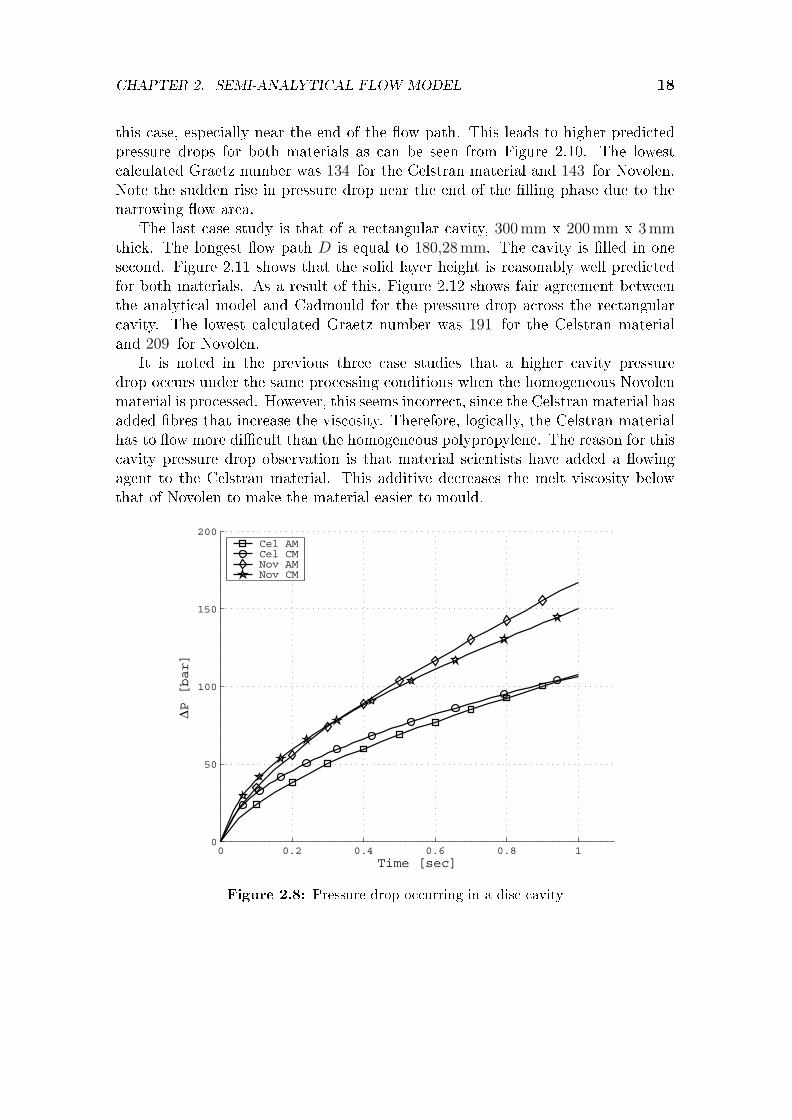
The �rst case study is the �lling of a 500mm diameter disc, 3mm thick andinjection occurs along the circumference of an 80mm diameter piston into thecavity. Therefore the �ow path length is shown in Figure 2.7 as 210mm. The discis �lled in one second at a constant �ow rate. Figure 2.7 shows that the growthof the solid layer along the �ow path (a radial line) is underestimated, relative toCadmould for both materials. The pressure drop along the �ow path relates wellto the results obtained with Cadmould (Figure 2.8). The lowest calculated Graetznumber was 209 for the Celstran material and 230 for Novolen.
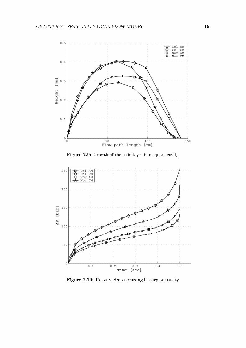
The second case study involves a square cavity of 200mm length and breadth,and 2mm thick. The injection point is in the centre and the longest �ow path Dis equal to 100
√2 mm. The cavity is �lled in 0,5 seconds. As can be seen from
Figure 2.9, the semi-analytical model overestimates the growth of the solid layer in
CHAPTER 2. SEMI-ANALYTICAL FLOW MODEL 18
this case, especially near the end of the �ow path. This leads to higher predictedpressure drops for both materials as can be seen from Figure 2.10. The lowestcalculated Graetz number was 134 for the Celstran material and 143 for Novolen.Note the sudden rise in pressure drop near the end of the �lling phase due to thenarrowing �ow area.
The last case study is that of a rectangular cavity, 300mm x 200mm x 3mmthick. The longest �ow path D is equal to 180,28mm. The cavity is �lled in onesecond. Figure 2.11 shows that the solid layer height is reasonably well predictedfor both materials. As a result of this, Figure 2.12 shows fair agreement betweenthe analytical model and Cadmould for the pressure drop across the rectangularcavity. The lowest calculated Graetz number was 191 for the Celstran materialand 209 for Novolen.
It is noted in the previous three case studies that a higher cavity pressuredrop occurs under the same processing conditions when the homogeneous Novolenmaterial is processed. However, this seems incorrect, since the Celstran material hasadded �bres that increase the viscosity. Therefore, logically, the Celstran materialhas to �ow more di�cult than the homogeneous polypropylene. The reason for thiscavity pressure drop observation is that material scientists have added a �owingagent to the Celstran material. This additive decreases the melt viscosity belowthat of Novolen to make the material easier to mould.
0 0.2 0.4 0.6 0.8 10
50
100
150
200
Time [sec]
∆P [bar]
Cel AMCel CMNov AMNov CM
Figure 2.8: Pressure drop occurring in a disc cavity
CHAPTER 2. SEMI-ANALYTICAL FLOW MODEL 19
0 50 100 1500
0.1
0.2
0.3
0.4
0.5
Flow path length [mm]
Height [mm]
Cel AMCel CMNov AMNov CM
Figure 2.9: Growth of the solid layer in a square cavity
0 0.1 0.2 0.3 0.4 0.50
50
100
150
200
250
Time [sec]
∆P [bar]
Cel AMCel CMNov AMNov CM
Figure 2.10: Pressure drop occurring in a square cavity

CHAPTER 2. SEMI-ANALYTICAL FLOW MODEL 20
0 50 100 1500
0.1
0.2
0.3
0.4
0.5
0.6
0.7
Flow path length [mm]
Height [mm]
Cel AMCel CMNov AMNov CM
Figure 2.11: Growth of the solid layer in a rectangular cavity
0 0.2 0.4 0.6 0.8 10
25
50
75
100
125
150
Time [sec]
∆P [bar]
Cel AMCel CMNov AMNov CM
Figure 2.12: Pressure drop occurring in a rectangular cavity

CHAPTER 2. SEMI-ANALYTICAL FLOW MODEL 21
In some situations, a cavity will be �lled in a time that will minimise the pressuredrop experienced during �lling. However, if this �lling time is too long, a largerinjection pressure capacity machine may be used, since this will save cost duringthe machine life-time as the part cycle time will reduce. The �ll rate directlyin�uences the Graetz number, but the analytical model is only applicable to "large"Graetz numbers. It is therefore worth investigating what the in�uence is of theGraetz number on the accuracy of the semi-analytical model and what acceptablenumerical values for the Graetz number would be.
The case studies conducted (Figures 2.13 to 2.18) show the in�uence of theGraetz number on the results obtained by the semi-analytical model for the samecase studies shown in Figures 2.7 to 2.12. It is compared to numerical resultsobtained from Cadmould. The Graetz number reported in the �gures is the smallestcalculated at the end of the �lling stage under constant �ow rate. The objectivewas to �nd the �lling time for which the pressure drop across the cavity will be aminimum when numerically calculated. These pressure drops are then comparedto those found by the analytical model. It is also checked if this local minimumoccurs at more or less the same �lling time for both the analytical and numericalresults. Again CM indicates to the results obtained from Cadmould and AM thesemi-analytical model results.
Figures 2.13 and 2.14 show that for the disc cavity the pressure drop resultsdi�er strongly between the two models when the Graetz number drops below 100 .The analytical model estimates the lowest pressured drop around a two seconds�lling time. However, Cadmould estimates these minima at around four secondsfor both materials. At two seconds the error of the semi-analytical model is 6% inthe case of the Novolen material and less in the case of Celstran. At 4 seconds thiserror grows to 59% in the worst case which is again for the Novolen material. Atthis point the Graetz number is well below 100 at 37 .
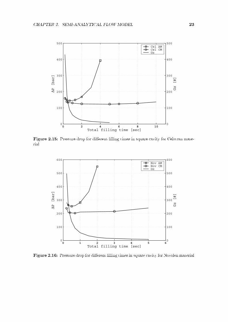
In the case of the square cavity shown in Figures 2.15 and 2.16, the analyticalmodel predicts the smallest pressure drop at around a �lling time of one secondfor both materials. This compares well to the �lling times found by Cadmould,especially in the case of the Novolen material. The minimum pressure drop variesvery little across a �lling time of one to ten seconds in the case of the Celstranmaterial. The error of the semi-analytical model is at most 33% for the Novolenmaterial case at a �lling time of one second. At this point the Graetz number isequal to 57 .
In the case of the rectangular cavity (Figures 2.17 and 2.18), both models predicta minimum pressure drop at around a two seconds cavity �ll time. In the case of theNovolen material it is noted that the analytical model calculates a shorter optimal�lling time corresponding to a minimum pressure drop compared to Cadmould.The semi-analytical model's error is 49% at most for the Novolen case at a �llingtime of two seconds. At this point the Graetz number is equal to 83 .
It can be seen from these results that the semi-analytical model is reasonably

CHAPTER 2. SEMI-ANALYTICAL FLOW MODEL 22
0 2 4 6 8 10 120
50
100
150
200
250
300
∆P [bar]
Total filling time [sec]0 2 4 6 8 10 12
0
100
200
300
400
500
600
Gz [#]
Cel AMCel CMGz
Figure 2.13: Pressure drop for di�erent �lling times in disc cavity for Celstran material
0 2 4 6 8 10 120
100
200
300
400
500
600
700
∆P [bar]
Total filling time [sec]0 2 4 6 8 10 12
0
100
200
300
400
500
600
700
Gz [#]
Nov AMNov CMGz
Figure 2.14: Pressure drop for di�erent �lling times in disc cavity for Novolen material
CHAPTER 2. SEMI-ANALYTICAL FLOW MODEL 23
0 2 4 6 8 100
100
200
300
400
500
∆P [bar]
Total filling time [sec]0 2 4 6 8 10
0
100
200
300
400
500
Gz [#]
Cel AMCel CMGz
Figure 2.15: Pressure drop for di�erent �lling times in square cavity for Celstran mate-rial
0 1 2 3 4 5 60
100
200
300
400
500
600
∆P [bar]
Total filling time [sec]0 1 2 3 4 5 6
0
100
200
300
400
500
600
Gz [#]
Nov AMNov CMGz
Figure 2.16: Pressure drop for di�erent �lling times in square cavity for Novolen material

CHAPTER 2. SEMI-ANALYTICAL FLOW MODEL 24
0 2 4 6 8 100
50
100
150
200
250
300
∆P [bar]
Total filling time [sec]0 2 4 6 8 10
0
100
200
300
400
500
600
Gz [#]
Cel AMCel CMGz
Figure 2.17: Pressure drop for di�erent �lling times in rectangular cavity for Celstranmaterial
0 1 2 3 4 5 60
50
100
150
200
250
300
∆P [bar]
Total filling time [sec]0 1 2 3 4 5 6
0
100
200
300
400
500
600
Gz [#]
Nov AMNov CMGz
Figure 2.18: Pressure drop for di�erent �lling times in rectangular cavity for Novolenmaterial

CHAPTER 2. SEMI-ANALYTICAL FLOW MODEL 25
well suited to �nd the �lling time that will correspond to a minimal pressure dropacross the cavity as long as the Graetz number stays above 100 . Numerical simu-lations can then be carried out around this approximate optimum �lling time anda better estimate for the pressure drop can be calculated. It is noted that thepressure drop computed by the semi-analytical model is higher than the pressuredrop computed by Cadmould. This would mean that machines designed from thesevalues will be slightly over designed and may be able to manufacture either slightlylarger parts in the same time or produce the same part in a quicker cycle time.
2.5 Conclusion
The results presented in this chapter show that the semi-analytical model givesreasonable results for the pressure drop across the cavity when compared withnumerical results obtained with Cadmould. The main restriction of the model isthat too high pressure drops are predicted when the Graetz number drops below100 . The reason for that is the overestimation of the solid layer thickness due tohigher conduction between the molten material and the solid layer to the cavitywall. Due to the associated smaller �ow area, the overestimated solid layer growthleads to a higher pressure drop than calculated with Cadmould. Otherwise, themodel can be used for cavities with �ow path length to cavity thickness aspectratios in the range of the case studies presented here. The model provides a quickway of estimating the pressure drop across the cavity during �lling, where numericalsolutions would have been too cumbersome and time consuming.
The geometry creation and computation time for the models presented here aremodest to insigni�cant. It is noted that the largest pressure errors occur towardsthe end of the �lling phase. In practice a constant pressure control strategy is usedfor the last part of the �lling phase. The machine sizing calculations are thereforebased on the pressures encountered somewhat before the end of the �lling phase.This �lling method is shown in Figure 2.19. Case a shows a constant �ow ratethroughout the �lling phase. In case b the �ow rate is kept constant up to a certaintime and it is followed then by �lling under constant pressure until the cavity iscompletely �lled.
Since the pressures encountered during mould �lling are related to the �llingrate, the �lling rate can in practice be reduced if the pressures would have exceededthe design values for a given machine size. Also, the �lling phase is normally muchshorter than the cooling phase and the potential e�ects of the under/over predictionof pressure is restricted to a small part of the �lling phase. Therefore, the in�uenceof the largest pressure errors (i.e. those at the end of the �lling phase) on themachine size and cycle time estimation is small. These pressure errors will havea small in�uence on the total machine cost, and the semi-analytical model can beexpected to give useful results for machine sizing studies and cost assessments.

CHAPTER 2. SEMI-ANALYTICAL FLOW MODEL 26
pressureloss pressure
loss
�ow rate �ow rate
time time
a bO O
Figure 2.19: Cavity pressure loss and material �ow rate during mould �lling
Computing times for the analytical model is insigni�cant on a 3GHz computer.The computation time for the numerical results is sensitive for the �nite meshdensity used to model the cavities. The case studies presented here comprised ofrelatively coarse meshes to keep the computation time reasonably low as manysimulations were carried out. Computation time varied between 30 seconds and 3minutes. The semi-analytical model will therefore yield substantially faster opti-misation calculations, in addition to shorter pre- and post-processing times. Oncea layout design has been selected, using the semi-analytical model presented here,�nal optimisation and design re�nement can be done by using a numerical �owsimulation package, such as Cadmould.

Chapter 3
Machine Design Concepts
3.1 Introduction
When the work presented in this dissertation started, two experimental machineshad already been built and used for investigations of the lomolding process (John-son, 2006). A few shortcomings of LM2 were identi�ed during these investigations.These shortcomings were evaluated by various people involved in the project andled to the formulation and evaluation of new machine layout concepts (Goussardand Basson, 2006b). This was an essential step to ensure that a good conceptwas further developed and optimised. Sometimes it occurs in practice that a badconcept is optimised and made to work as a result of very tight time deadlines.Therefore, concepts were generated to maximise lomolding's potential advantagesand minimise the e�ects of the expected disadvantages. Concepts were generatedto ful�l the following required operations:
� transferring melt from metering phase to moulding phase
� minimising part defects caused by premature melt solidi�cation
� elimination of accurate melt metering
This chapter explains and describes many of the design concepts that wereevaluated as candidates for a new design of the lomolding machine. Each conceptis described in detail: how it works, what the positive and negative aspects areand whether it was considered for further development. It explains why the designof the machine as described in Chapter 1 was chosen as a new design for furtherdevelopment. The next two sections describe lomolding's expected advantages anddisadvantages. The design requirements against which the concepts were evaluated,were formulated with these advantages and disadvantages in mind.
27

CHAPTER 3. MACHINE DESIGN CONCEPTS 28
3.1.1 Lomolding's expected advantages
Lomolding o�ers three distinct expected advantages when compared to injectionmoulding. Firstly, lower material shear rates are expected as a result of replacingthe sprue with a large injection opening. Secondly, longer �bres can be injected intoreinforced parts, since �bre attrition occurring in the sprue does not occur. Thirdly,the larger injection opening potentially reduces the needed injection pressure whencompared to injection moulding. This, as well as the lower material shear rate atthe material injection point, provides the ability to mould against skins (a thindelicate material inserted in the mould). These advantages are discussed in detailin the following paragraphs.
3.1.1.1 Lower material shear rates
Lomolding o�ers a lower material shear rate at the material entry point to thecavity compared to injection moulding. The reason for that is the larger �ow area(the piston diameter is much larger than that of the sprue) that reduces the meltpressure gradient at the entry point. The material shear rate is directly in�uencedby the pressure gradient. Material shear stress results in the build up of residualstresses during processing which often leads to part warpage when the part is cooledand released from the mould (Matsuoka et al., 1991).
3.1.1.2 Less �bre attrition
Thermoplastic materials are often reinforced with �bres to enhance their mechanicalstrength, sti�ness, etc. This is done by adding short lengths (typical 1mm to 2mm)of �bre to the material that is plasticised in injection moulding. Longer lengths of�bre will either be broken in the plasticising screw, in the sprue or at the entrygate to the cavity. Fibre breakage due to bending (one of the reasons for �breattrition) occurs as the �bres rotate against the material �ow direction. Thesebending forces are proportional to the material shear rate (Zhang and Thompson,2005). Therefore, less �bre attrition will occur during lomolding as the small sprueis replaced by a ring gate.
Material preparation for injection moulding is a very costly process. As an ex-ample: suppliers often combine the thermoplastic material with �bres and a �owingagent that changes the viscosity of the melt. Mixing of the material is done in amaterial extruder where the materials are heated and mixed. This process, calledcompounding, is similar to the material plasticising stage of injection moulding ma-chines. The molten material is then pushed through small openings and fed througha water bath to allow the strings to cool down. The strings are then chopped intoshort lengths and dried. Short lengths are required, otherwise it will be impossi-ble to remelt the material in a plasticiser. This chopping process and subsequentremelting in the plasticiser obviously reduces the average �bre length considerably.

CHAPTER 3. MACHINE DESIGN CONCEPTS 29
The compounder can be coupled directly to a lomolder (or an injection moulder)if a melt accumulation chamber is added. As a result, the extruding of strings,cooling, chopping and drying process can be skipped.
Therefore, lomolding o�ers the advantage of less �bre attrition compared to in-jection moulding and even more if the lomolder is directly fed from a compounder inwhich case the plasticising stage (that accounts for a large portion of �bre attrition)is skipped.
3.1.1.3 Moulding against skins
The lower material shear rate during the cavity �lling stage also lends itself tomoulding against skins. During this process a thin skin of material (for example aprinted logo) is put in the mould cavity on the opposite side of the injection point.The skin is bonded to the thermoplastic during injection. This process is di�cultwith injection moulding, since the high material shear rate and pressures at theentry gate often damage the skin. Moulding against skins results in non-uniformcooling of the part, since the skin restricts the heat transfer on one side. Wheninjection moulding is used to mould against skins, the melt temperature is oftenincreased to decrease the melt viscosity. This leads to a lower melt shear rate.However, this extra heat must be removed during the cooling phase and elevatesthe non-uniform cooling problem.
3.1.2 Lomolding's expected disadvantages
The exact amount of molten material has to be measured o� in a metering deviceprior to the injection phase. This is necessary since the moulding piston's face formspart of the cavity wall once in the closed position. Too much material will resultin an elevated piece of material ending up under the moulding piston. Too littlematerial will either result in an under �lled part or a part with insu�cient packing(such a part will shrink more and part warpage might also be larger). Exact shotmeasurement can be overcome as the stopping position of the moulding piston toproduce a good part will be known and can be measured during operation. With aclosed loop control system, the amount of material needed can be easily correctedif necessary.
Since the moulding piston's face forms part of the cavity wall, it ideally needsto be at the same temperature as the cooled part cavity to ensure uniform coolingof the part, because di�erent cooling gradients also contribute to part warpage(Matsuoka et al., 1991). After material metering is completed, the melt is pushedin front of the moulding piston prior to the injection phase. During this time themoulding piston's face ideally needs to be hot to prevent melt solidi�cation againstit. This poses a problem, since it is impossible for both requirements to be met.Dymond (2004) showed that as long as the time the material spends in front of the

CHAPTER 3. MACHINE DESIGN CONCEPTS 30
@@@I
insulatingrequired
@@@I
hot mouldingcylinder wall
@@
@I
solidi�edmaterial
���
heaterbands
� cold cavity wall
?
melt
Figure 3.1: Insulation problem resulting in premature melt solidi�cation
moulding piston is kept short, cooling of the piston face will not result in a partdefect due to a solidi�ed disc being pushed into the part.
The same type of problem is encountered where the moulding cylinder's wall isin contact with the part cavity (refer to Figure 3.1). The cylinder needs to be heatedto prevent melt solidi�cation prior to injection. However, the cavity wall must becold, especially in the vicinity of the moulding cylinder to ensure uniform cooling.LM2 had a small opening between the mating surfaces of the part cavity and thecylinder. The opening had to be small enough to prevent melt leakage. A cylinderwall temperature gradient still existed and this lead to premature melt solidi�cationmainly as a result of a too long material transferring time from the metering unitto the position in front of the moulding piston. This solidi�ed material layer wasscraped along when the moulding piston pushed the material into the cavity. Thisresulted in a part defect. A possible solution to this problem is to provide a smallpiece of insulating material between the moulding cylinder and the cavity. Thisadds a little complexity as well as maintenance due to wear of this extra insulation,especially if �bre reinforced material is processed. Another possible solution is to

CHAPTER 3. MACHINE DESIGN CONCEPTS 31
make the contact area between the part cavity and the moulding cylinder as smallas possible.
3.2 Design Requirements
This section analyses the needs of the client that the lomolder has to ful�l. Theneeds are translated into speci�cations. The speci�cations lead to several conceptsthat are discussed in the subsequent sections. The best one is chosen that po-tentially achieves all of the speci�cations. Focus is placed on the metering unit,hot runner con�guration and the moulding unit, since these subsystems di�er frominjection moulding. Special attention is given to the existing disadvantages of LM2.
3.2.1 Prevention of premature melt solidi�cation
The moulding cylinder temperature must transition from melt temperature (>200�)where the melt is received, to mould wall temperature (<55�) at the junction withthe part cavity. The region below melt temperature should be kept as short as pos-sible and the time that the melt is in contact with cold parts of the cylinder shouldbe kept as short as possible to prevent premature solidi�cation as discussed inSection 3.1.2.
3.2.2 Prevention of �bre attrition
Fibre attrition results in a lower average �bre length and this leads to weakermoulded parts than expected. Therefore, �bre breakage must be minimised sincemoulding long �bres is potentially a signi�cant advantage of lomolding over injec-tion moulding. Fibre breakage occurs in regions of high shear rate which causesbending moments on the �bres (Zhang and Thompson, 2005) (Jones, 1998). There-fore these regions of high shear rate are evaluated using equations published byRichardson (1983) to determine the pressure drop in runner sections.
3.2.3 Minimisation of part cycle time
A shorter cycle time means a better lomolder e�ciency. It was decided to preferablydo melt metering in parallel with the part cooling phase in order to reduce theoverall cycle time. The part cycle time can also be shortened by having the meteringcylinder inject some of the melt into the part cavity during the melt transfer phase.In order to accomplish this, the volume in front of the moulding piston must beless than the part volume.

CHAPTER 3. MACHINE DESIGN CONCEPTS 32
shot size too large
exact shot size
shot size too small
Figure 3.2: Part shapes as a result of di�erent material shot sizes
3.2.4 Accurate metering
Inaccurate metering leads to the part defects shown in Figure 3.2. The varying partthickness under the moulding piston may be unacceptable when tight tolerancesare needed. Measuring the exact amount of molten material needed is challenging,since thermoplastic materials expands and shrinks considerably with changes intemperature (Osswald and Menges, 1995).
3.2.5 Compactness of moulding unit
This was not a customer need as such, but is necessary as a design requirement.The moulding unit goes through the stationary platen. The stationary platen willpartially loose its sti�ness if the hole in the platen is too large as a result of atoo bulky moulding and runner unit combination. Preferably, the ejection systemmust be situated on the same platen as the ring gate, otherwise the ejected partwill have a piston mark on one side and ejection pin markings on the other side. Acompact moulding unit provides more available space for the ejection system. Thisre�nement is discussed in Chapter 4.
3.2.6 Easy material purging
It is important for the client to easily change between di�erent materials or di�erentcolours as needed. Therefore, regions where molten material can remain instead of�owing through should be avoided as far as possible.

CHAPTER 3. MACHINE DESIGN CONCEPTS 33
3.2.7 Easy maintenance
Easy maintenance of the lomolder is essential. Therefore, the lomolder must beable to make a large number of parts with the minimum of major maintenance(e.g. replacement or refurbishment of complex parts).
3.3 Concepts Developed to Transfer Melt
A number of concepts were generated to ful�l the goal of feeding molten materialfrom a plasticiser or extruder into a metering cylinder where the exact amount ofmaterial to �ll the cavity is measured o�, followed by transferring the measured o�material to in front of an injection piston, which then pushes this material into apart cavity. The main objective is to decrease the melt transfer time. Secondaryobjectives include minimising the number of parts (less complexity) and developingan as compact design as possible.
The concepts focus on a distinct aspect that were found lacking on LM2. Themelt measuring time overshadowed the cycle time of the part with a volume of589 cm3. The transfer unit runners were too small and this led to high pressuresrequired to transfer the melt from the metering cylinder to a position in front of themoulding piston. It also led to high melt velocity speeds and therefore unnecessaryhigh strain rates developed in the material that escalated �bre attrition. Thisaspect needed to be improved.
Concept 1 (Figure 3.3) shows an inline metering piston and moulding piston.The melt is moved by this double piston con�guration and is measured betweenthe two pistons. Once the correct volume of molten material has been measured,the melt is pushed through a valve in the moulding piston head and transferred tothe front of the moulding piston. The valve in the piston then closes to preventback �ow of the melt and the moulding piston pushes the melt into the cavity tothe point where its face forms part of the cavity wall at the end of the �lling phase.
The concept's advantages include the compactness of the design (which reducesthe size of the hole required in the stationary platen through which the mouldingunit passes) and that material metering can be done in parallel with the part coolingphase.
The concept's main disadvantages are: The valve in the moulding piston createsa high melt velocity section. This increases the shear rate on the material and willcause �bre length attrition before the cavity even starts to �ll. This smaller areamay also be blocked by material with high �bre content. The inline meteringpiston and moulding piston leads to a complex mechanical design with increasedmaintenance times and maintenance di�culties expected. Insulating the hot sideof the moulding piston facing the metering piston while metering is being donefrom the cold side (that forms part of the cavity wall) required for part cooling,

CHAPTER 3. MACHINE DESIGN CONCEPTS 34
?
mouldingpiston
�����
meteringpiston
6
cavity
6
melt
Figure 3.3: Concept 1: Inline pistons where melt is fed through the moulding piston
also poses di�culties. For instance, it will be di�cult to cool the small valve headas the cooling tubes must run through the thin moulding shaft. The valve in themoulding piston head will result in an extra piston mark on the moulded part.Uniform cooling of the moulding piston on the cavity side will also be di�cult toachieve due to the valve in the piston. Due to these disadvantages, concept 1 is notattractive.
Concept 2 (Figure 3.4) also has an inline metering piston and moulding piston,but the melt is measured behind the metering piston and pushed in front of themoulding piston via a bypass runner. Once the shot has been transferred in frontof the moulding piston, a valve in the bypass runner closes to prevent back�ow ofmaterial during the moulding phase. Next, the moulding piston pushes the meltinto the cavity and its face forms part of the cavity wall at the end of the �llingphase.
The main concept advantages include compactness of the design, although lessthan concept 1. Also, metering can be done while the part is being cooled. Thehot melt is not in contact with the moulding piston during the measuring phase.Therefore, cooling of the moulding piston is less of a problem than in concept 1.
The disadvantages of the concept are: The inline metering piston and mouldingpiston leads to a complex design as in concept 1. Leakage of melt past the meteringpiston will accumulate between the metering piston and moulding piston. It will

CHAPTER 3. MACHINE DESIGN CONCEPTS 35
?
mouldingpiston
�����
meteringpiston
6
cavity
6
melt
Figure 3.4: Concept 2: Inline pistons where melt is measured behind the metering pistonand fed around the moulding piston
be very di�cult to purge the melt from this position and this will lead to increasedmaintenance times. Concept 2 is therefore not attractive.
Concept 3 (Figure 3.5) is similar to concept 2, except that the melt is measuredbetween the two pistons. It retains most of the disadvantages of concept 2, as wellas the added complication that the moulding piston has to be hot on the meteringside and cold on the cavity side. This concept holds no advantages above concept 2,except that the problem with melt leaking past the moulding piston in concept 2has been eliminated. Therefore this concept is not considered further as well.
Concept 4 (Figure 3.6) shows a combined metering and moulding piston and across-fed shut-o� valve. The melt is measured between the moulding piston and theshut-o� valve and, once the correct volume of molten material has been measured,a valve closes in the melt inlet to prevent back �ow of the melt during the cavity�lling phase. After the shut-o� valve opens, the moulding piston pushes the meltinto the cavity and its face forms part of the cavity wall at the end of the �llingphase.
The concept's advantages include the elimination of the metering cylinder. Theshut-o� valve does not need accurate position control over the range of movement,except that a precise stopping position is required, but this can be achieved with amechanical stop.

CHAPTER 3. MACHINE DESIGN CONCEPTS 36
?
mouldingpiston
�����
meteringpiston
6
cavity
6
melt
Figure 3.5: Concept 3: Inline pistons where melt is measured between the pistons andfed around the moulding piston
The concept's disadvantages are: Metering cannot be done in parallel with thepart cooling phase and the moulding piston head is in contact with the melt duringthe whole metering phase. This concept is therefore not attractive.
Concept 5 (Figure 3.7) shows an inline moulding piston and rotating measuringcavity. Melt from the plasticiser �lls the �xed volume measuring cavity. Once �lled,it rotates through 90� and this allows the moulding piston to push the materialshot into the cavity. The moulding piston face forms part of the cavity wall at theend of the �lling phase.
The concept's advantages include the elimination of the metering cylinder. Therotating measuring cavity does not need accurate position control, except that theposition in which it must stop before the moulding piston moves forward must bevery accurate. The moulding piston is not heated during the melt measuring phase.
The concept's disadvantages are: The shot is a �xed volume and cannot com-pensate for density changes due to inevitable melt temperature variations. Further,only parts with one volume can be made on the machine. Metering cannot be donein parallel with the part cooling phase. Heating the rotating body to prevent meltsolidi�cation is also di�cult. This concept was implemented in the �rst experimen-tal lomolding machine, but was found unattractive for the reasons given above.
Concept 6 (Figure 3.8) shows a moulding piston and a section of moving cavity
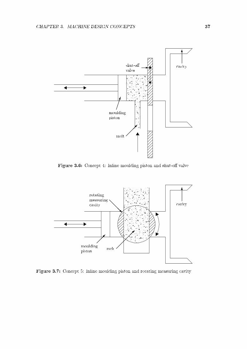
CHAPTER 3. MACHINE DESIGN CONCEPTS 37
-shut-o�valve
�����
mouldingpiston
6
cavity
��
��
melt
Figure 3.6: Concept 4: Inline moulding piston and shut-o� valve
@@
@@R
rotatingmeasuringcavity
����
mouldingpiston
6
cavity
��
����
melt
Figure 3.7: Concept 5: Inline moulding piston and rotating measuring cavity

CHAPTER 3. MACHINE DESIGN CONCEPTS 38
@@
@@@R
movingcavitywall
��
����
mouldingpiston
6
cavity
��
����
melt
Figure 3.8: Concept 6: Inline moving cavity wall
wall opposite the moulding piston (i.e. another piston that moves relative to themoving platen). The melt is measured between the moulding piston and the movingcavity wall. Once the shot is measured, the moving cavity wall retracts and themoulding piston pushes the melt into the cavity. The moulding piston face formspart of the cavity wall at the end of the �lling phase.
Concept advantages include the inline replacement of the metering cylinder(compactness). However the design on the moving platen side will be complex (e.g.actuators on moving platen required). It will also complicate the placement andoperation of the part ejection system.
Further disadvantages included that metering cannot be done in parallel withthe part cooling phase, that the cool moulding piston and the moving wall are incontact with the melt for the whole metering period and that both the mouldingpiston and the moving wall will leave marks on the part. The concept was discardedfor these reasons.
Concept 7 (Figure 3.9) shows a con�guration where metering is done with apositive displacement pump. The pump is heated to prevent melt solidi�cation.The melt is transferred to in front of the moulding piston and then pushed into thecavity. The moulding piston face forms part of the cavity wall at the end of the�lling phase. Whether replacing the metering cylinder with a positive displacementpump will increase the cycle time, is not certain.
However, �bre attrition is likely to occur in the pump when �bre reinforced

CHAPTER 3. MACHINE DESIGN CONCEPTS 39
@@
@@R
positivedisplacementpump
@@
@@R
mouldingpiston
6
cavity
?
melt
Figure 3.9: Concept 7: Positive displacement metering
material is processed. The accuracy of the metered shot is di�cult to determine.This concept was deemed unattractive since it replaces a relatively simple andcontrollable metering cylinder with a more complex pump.
Concept 8 (Figure 3.10) has a separate metering cylinder and moulding cylinder.After the melt is measured o� in the metering cylinder, a valve closes in the meltinlet runner (not shown) to prevent back �ow of the melt during the moulding phaseand a valve between the metering and moulding cylinders (also not shown) opens.The shot is then transferred to the front of the moulding piston. The mouldingpiston pushes the melt into the cavity and forms part of the cavity wall at the endof the �lling stroke.
The concept's advantages include that metering can be done during the partcooling phase and that the moulding piston is not in contact with the melt duringthe metering phase.
The main disadvantage is that this concept is more bulky than the previousinline concepts.
3.4 Concepts Developed to Minimise Part Defects
Caused by Premature Melt Solidi�cation
All parts produced on the second prototype lomolder had a defect at the meltinjection point. Analysis (Dymond, 2004) showed that the defect was caused by a

CHAPTER 3. MACHINE DESIGN CONCEPTS 40
?
mouldingpiston
@@
@@R
meteringpiston
6
cavity
-melt
Figure 3.10: Concept 8: Separate metering and moulding cylinders
� meteringpiston
����
mouldingpiston
� transferrunner
@@
@@I
solidi�edmaterial
?
cavity
?
melt
Figure 3.11: Solidi�ed ring of material as a result of a too long metering transfer time

CHAPTER 3. MACHINE DESIGN CONCEPTS 41
@@
@@
@@R
mouldingpiston
@@
@@R
meteringpiston
��
�
hot gasinjected
6
cavity
-melt
Figure 3.12: Concept 9: Heated piston face
solidi�ed ring of material being pushed into the part at the end of the mouldingpiston stroke. Concepts developed here try to minimise the time that the meltspends in contact with the moulding piston (before completing mould �lling) andthe moulding cylinder respectively. Figure 3.11 shows this solidi�ed ring of materialin black on the sides of the moulding cylinder. The solidi�ed layer is thicker onthe bottom half of the moulding cylinder as the melt collects here during the longmetering transfer phase.
Dymond (2004) showed that the largest contributor to this solidi�ed ring ofmaterial was the solidi�ed layer of material being scraped along by the mould-ing cylinder's face. It overshadowed the solidi�ed layer that formed on the cooledmoulding cylinder's face itself. The moulding piston has to be water cooled (notshown in the concepts) as it heats up during the melt injection phase. Preferably, itmust be close to the cavity wall temperature at the end of the injection phase. Oth-erwise, irregular cooling will result in a part defect. The goal of concepts developedhere, was to get rid of part defects caused by the moulding piston temperature.
Concept 9 (Figure 3.12) shows concept 8 (Figure 3.10) with the introductionof a hot gas being blown over the face of the moulding piston. The piston face ispre-heated by the hot gas stream before the melt is transferred to the front of themoulding piston. During the moulding phase the heat from the piston face willdissipate quickly into the piston head while the melt is injected into the cavity.
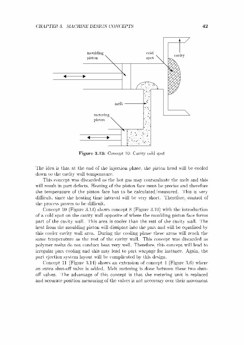
CHAPTER 3. MACHINE DESIGN CONCEPTS 42
@@
@@
@@R
mouldingpiston
@@
@@R
meteringpiston
@@
@@@R
coldspot
6
cavity
-melt
Figure 3.13: Concept 10: Cavity cold spot
The idea is that at the end of the injection phase, the piston head will be cooleddown to the cavity wall temperature.
This concept was discarded as the hot gas may contaminate the melt and thiswill result in part defects. Heating of the piston face must be precise and thereforethe temperature of the piston face has to be calculated/measured. This is verydi�cult, since the heating time interval will be very short. Therefore, control ofthe process proves to be di�cult.
Concept 10 (Figure 3.13) shows concept 8 (Figure 3.10) with the introductionof a cold spot on the cavity wall opposite of where the moulding piston face formspart of the cavity wall. This area is cooler than the rest of the cavity wall. Theheat from the moulding piston will dissipate into the part and will be equalised bythis cooler cavity wall area. During the cooling phase these areas will reach thesame temperature as the rest of the cavity wall. This concept was discarded aspolymer melts do not conduct heat very well. Therefore, this concept will lead toirregular part cooling and this may lead to part warpage for instance. Again, thepart ejection system layout will be complicated by this design.
Concept 11 (Figure 3.14) shows an extension of concept 4 (Figure 3.6) wherean extra shut-o� valve is added. Melt metering is done between these two shut-o� valves. The advantage of this concept is that the metering unit is replacedand accurate position measuring of the valves is not necessary over their movement

CHAPTER 3. MACHINE DESIGN CONCEPTS 43
@@
@@
@@R
mouldingpiston
dual shut-o� valves
6
cavity
-melt
Figure 3.14: Concept 11: Inline moulding piston and dual shut-o� valves
range. Also, the moulding piston is not heated during the metering phase. However,the stop position of the valves is critical, otherwise moulding piston damage willoccur. A mechanical stop can be implemented to achieve this. On the negative sideit is noted that this concept again has a �xed shot volume, which does not allowcompensation for melt temperature variation or the production of thicker parts forinstance. Therefore, concept 11 is discarded.
Dymond (2004) showed that complexity added by the above three concepts isnot warranted. He showed that premature melt solidi�cation is not a problemand will not cause part defects if the melt is transferred quickly in front of themoulding piston after the metering phase and if the melt is quickly injected intothe part cavity.
3.5 Concepts Developed to Eliminate the Need
for Accurate Metering
Concepts developed in this section provide the opportunity for adding or removingmolten material after crude shot measuring is done.
Concept 12 (Figure 3.15) shows a moulding piston with a melt �lling port andmelt return port in front of the piston. The volume in front of the piston is larger

CHAPTER 3. MACHINE DESIGN CONCEPTS 44
@@
@@
@@R
mouldingpiston
������
CCCCCW
pressuresensors
-cavity
melt inlet melt return
����:valve
Figure 3.15: Concept 12: Pressure metering to replace accurate melt metering phase
than the part volume. This entire volume is �lled with molten material and accuratemelt metering is replaced by measuring the pressure at predetermined points in thepart cavity during the injection phase. Once predetermined pressures are reached inthe cavity the valve in the melt return line opens and the excess melt is transferredback to a melt accumulator until the moulding piston reaches its stopping position.
This concept was not further considered, since accurate pressure measurementin small time increments as required during part �lling is very di�cult. The meltmay also block the metering points after some time and pressure measurement maybe inaccurate. The repeatability of the process is also a point of concern.
Concept 13 (Figure 3.16) shows a smaller additional moulding piston added tothe machine con�guration. Melt is fed in front of the moulding piston and thenpushed into the part cavity. This initial material shot has a volume slightly lessthan needed to produce a part. Once the moulding piston reaches its intendedposition, the cavity is completely �lled by the additional piston. More than onesecondary injection point can be used. When the part is removed after the coolingphase, it breaks o� at these secondary �lling gates similarly to injection moulding.
This concept was discarded as it becomes complex with too many parts, espe-cially if more than one secondary injection point is used. Also, the small secondaryinjection points may block if �bre reinforced material is processed. This will resultin machine down time. Both of these two concepts will also result in an additionalmark left on the part.

CHAPTER 3. MACHINE DESIGN CONCEPTS 45
@@
@@
@@R
mouldingpiston
meltadditionpiston
-cavity
Figure 3.16: Concept 13: Melt injection after moulding piston reaches required position
3.6 Final Concept Selection
This chapter described the concepts that were evaluated as candidates for furtherdevelopment. Their working principles, advantages and disadvantages were ex-plained as well as the reasons why they were discarded or used for further develop-ment. Concept 8 was chosen as the best candidate for further design development.It best satis�ed the main design requirements listed in section 3.2 and had the sim-plest mechanical design (thus reducing development risks). Concepts attemptingto prevent premature melt solidi�cation (Section 3.4) were discarded as a resultof Dymond's results. The concepts of Section 3.5 were discarded as a result o�added complexity, increased cycle time and unreliability when repeatability andmaintenance problems are considered.
Lomotek Polymers built a next prototype lomolder based on the chosen conceptin partnership with an overseas company that manufactures injection mouldingmachines. This prototype is further used for machine re�nement and research.

Chapter 4
Machine Design Re�nement
4.1 Introduction
This chapter describes the re�nement of the chosen machine concept discussed inChapter 3. A parametric machine sizing model is developed that provides usefulinformation to set up an initial machine cost model. The parametric machine modelis con�gured to conceptualise di�erent sizes of piston moulding machines. Once themachine component sizing is done, purchase cost estimation can be done for thedi�erent components. The parametric model concentrates on the design of thecomponents of the lomolding unit, i.e. the metering- and moulding cylinders andthe �ow channels between them, since these components di�er signi�cantly fromthose found on general injection moulders. The plasticiser and clamping unit (thepart of the machine that opens and closes the mould halves) are essentially thesame as in injection moulding. Even though costing research in injection mouldingconcentrates mostly on part features and mould design (Chen and Liu, 1999) (Leeet al., 1997) and research related to machine costing and optimisation is usuallyproprietary to machine manufacturing companies (and therefore rarely published),the vast experience in the injection moulding industry can be relied on to providethese subsystems. The chapter outlines important aspects regarding machine layoutthat in�uences the cost of the lomolding unit. The lomolding unit consists of themetering unit, moulding unit and the runner �ow areas to transfer the melt to themoulding unit. Focus is then placed on the e�ects of cavity �lling time. Then melt�ow area calculations and critical material selection for di�erent machine parts arediscussed. This is followed by two extreme sizes of lomolders that are analysed ascase studies.
46

CHAPTER 4. MACHINE DESIGN REFINEMENT 47
4.2 Layout Design
Machine design and cost are mostly in�uenced by the diameter of the mouldingpiston. A small diameter piston means a smaller available area and therefore alower injection force is needed to inject the material compared to the case whena larger diameter piston is used. Choosing a moulding piston diameter is not atrivial task and is limited by boundaries. First, if the diameter is too small, thewhole process is comparable to traditional injection moulding where material is fedthrough the sprue and therefore, most of the advantages of lomolding as discussedin Chapter 3 are lost. Alternatively, if the diameter is too large, the process iscomparable to compression moulding and therefore very large forces are needed toproduce parts. Lomolding unit cost is strongly in�uenced by injection forces andtherefore the cost of the machine will also rise. It may even become impossible touse electric actuators as the power requirements may fall outside the ranges thatare currently available. The actuator sizing and cost issues are discussed in detailin Chapter 5.
Figure 4.1 shows a typical layout design provided by the parametric model. The�gure will be referred during the discussion of typical machine layout design issues.
4.2.1 Stationary platen hole
It was decided to put the metering cylinder behind the stationary platen, to reducethe required hole size in the stationary platen. As mentioned in Section 3.2, thehole reduces the sti�ness of the platen and therefore it must be as small as possible.Melt is delivered through an annular runner to a position in front of the mouldingpiston to ensure compactness.
4.2.2 Piston skirt
A skirt is �tted around the moulding piston and made of a softer material (moreabout the materials in Section 4.5) than the moulding cylinder. This skirt is ex-tended to serve as the valve between the metering cylinder and the moulding cylin-der. It must be long enough to completely seal of the port between the annularrunner and the moulding cylinder when the moulding piston is in the closed position(i.e. during the part cooling phase).
4.2.3 Metering unit orientation
The metering unit in Figure 4.1 shows a metering unit that is perpendicularlyplaced to the moulding unit. This con�guration makes the lomolding unit as awhole less compact, but has advantages. Having the metering unit parallel to themoulding unit, creates di�culties to position the actuators of both in the smaller

CHAPTER 4. MACHINE DESIGN REFINEMENT 48
a: moving mould halfb: stationary mould halfc: stationary platend: metering cylindere: moulding pistonf: runner blockg: moulding piston skirth: platen holei: annular runner
a b c
d
f
e
g
h
i
O O O
O
O
O
O
O
O? ?
? �
��������
��
��
��
�
CCCCCCCO
�����������
��
��
��
��
���
Figure 4.1: Moulding unit layout

CHAPTER 4. MACHINE DESIGN REFINEMENT 49
space available. Especially, the placement of the belts and pulleys in the case ofelectric drives will be challenging. Therefore, the perpendicular layout was chosen.It is noted that a perpendicular layout may also in�uence the operation of theejection system on the stationary platen.
4.2.4 Temperature gradients
The problem with having a hot moulding cylinder in close proximity to the coldstationary moulding half was discussed in Chapter 3. It was decided against usingan insulation section (as shown previously in Figure 3.1) as this adds complexityand extra maintenance. The insulation material will wear more quickly than themoulding cylinder and �bres (when reinforced material is processed) will get caughtat this point. It will also be di�cult to keep the moulding cylinder and the cavityring gate concentric to each other as close tolerances exists. Therefore, a thincircular contact area is introduced that will restrict heat transfer. Solidi�cation isnot a problem as long as the metering and moulding phase are done rapidly.
4.3 Machine Design Issues
This section describes di�erent issues regarding machine design that are applicableto all sizes of lomolders, e.g. forces in the main machine components. The rangeof machine sizes considered starts at a machine that is capable of manufacturing adisc with a diameter of 150mm. This is approximately equivalent to a bread boardsize product. A pallet of 1,0m x 1,0m forms the upper part threshold. Thesepallets are used in the packaging industry for instance.
4.3.1 E�ect of cavity �lling time
The piston moulding process is performed by the actions as described in Chap-ter 3 (Figure 3.10). The semi-analytical model (Chapter 2) provides the pressuredrop experienced in the part cavity during the moulding phase as an input to theparametric sizing model.
The cavity pressure loss, i.e. the di�erence between the cavity pressure underthe piston and that at the �ow front, is an important machine design parameter.The idealised relationship between the cavity pressure loss and the corresponding�ow rate time history are shown by the solid and dashed lines, respectively, inFigure 4.2 (repeated here for clarity).
Figure 4.2a shows a constant �ow rate and increasing pressure loss over time dueto the progression of mould �lling. These pro�les would give the minimum �ll time(which would give a cycle time advantage), but the machine would have to be ableto deliver a high moulding pressure and �ow rate simultaneously. Also, controlling

CHAPTER 4. MACHINE DESIGN REFINEMENT 50
pressureloss pressure
loss
�ow rate �ow rate
time time
a bO O
Figure 4.2: Cavity pressure loss and material �ow rate during mould �lling
the machine when the shot is even slightly too large or too small, would be verychallenging. Injection moulding is therefore not normally done in this manner andinstead a constant �ow rate is prescribed for only a certain part of the �lling phase(80% to 90% of the injection stroke) followed by �lling under constant pressureuntil the cavity is completely �lled (as shown in Figure 4.2b).
The change over point between the constant �ow rate phase and the constantpressure drop phase is treated as a user-speci�ed parameter in the parametricmodel. Once the cavity is completely �lled the part is packed under constantpressure. This step is necessary to minimise warpage and to avoid sink marksresulting from the material shrinkage during solidi�cation.
It can be seen from these graphs that a speci�c sized machine might be ableto produce larger (same thickness, larger area) parts than it was designed for byreducing the material �ow rate. However, it must be kept in mind that a minimummelt �ow rate is required to prevent a frozen melt front (no further cavity �lling ispossible) that will result in a short shot. Therefore, the longer �ow path is �lledin a longer time, resulting in the same melt pressure drop across the part cavitythat the machine was designed for. Thicker parts (i.e. larger volume) can alsobe manufactured, since the larger �ow area results in a lower cavity melt pressuredrop. The metering unit capacity places a limit on the higher volume parts.
The calculated maximum pressure drop (by the semi-analytical model) is used todetermine the force on the moulding piston. The clamping force that the clampingunit has to withstand is calculated in a similar manner.
The metering piston does not have to exert a pressure as large as that of themoulding piston since it only has to cope with the runner pressure losses and theearliest part of the �lling phase (only when the shot volume exceeds the swept

CHAPTER 4. MACHINE DESIGN REFINEMENT 51
volume of the moulding piston).The moulding and metering pistons can be driven either by hydraulic cylinders
or electric servo motors with ball screws. In both cases the following aspects haveto be kept in mind:
� The shaft of the hydraulic actuator or the rotating ball screw must withstandthe maximum axial force without buckling.
� The actuator must be able to deliver the required linear speed (determined bythe required �ow rate) combined with the required force (determined by thecavity pressure and a friction allowance) at the point in Figure 4.2b where thechange over from constant speed to constant pressure occurs. This point typ-ically constitutes a critical design point, since the maximum energy transferfrom the actuator to the piston occurs at that point in the �lling phase.
4.4 Melt Flow Areas
The melt �ow area directly in�uences the pressure gradient that the melt with-stands during transfer. The material shear rate is directly proportional to melt�ow pressure gradient. Fibre breakage due to bending (one of the reasons for �breattrition) occurs as the �bres rotate against the material �ow direction. Thesebending forces are also proportional to the material shear rate (Zhang and Thomp-son, 2005). The retention of longer �bres is expected to be one of the advantagesof lomolding and therefore it is important that shear rates are lower everywhere in�ow path upstream of the ring gate.
Concept 8 (Figure 3.10) was identi�ed as the most favourable for further de-velopment and Figure 4.1 shows a re�nement of that concept. The melt �ow pathis strongly in�uenced by the machine layout details: molten material is pushedfrom the plasticiser through a round hole (part of the runner block, Figure 4.1:f)upwards into the metering cylinder. The material cannot �ow into the mouldingcylinder at this stage, since the ports in the moulding cylinder wall are closed bythe moulding piston skirt during the part cooling phase (see Figure 4.3). After thepart has solidi�ed, the mould opens, the part is ejected, the mould closes again,and the moulding piston withdraws to its rear position. Then the melt is pushedby the metering cylinder through the runner block circular opening (Figure 4.4:a),through the semi-annular runner (Figure 4.4:b) and into the moulding cylinderthrough two ports in the moulding cylinder wall (Figure 4.4:c).
The semi-annular runner (Figure 4.4:b and Figure 4.5, where the hatched areaon the left shows the net �ow area) is included in the layout to minimise the sweptvolume of the moulding cylinder, the time that the melt is in contact with themoulding cylinder, and the length of the moulding piston skirt. The melt enters themoulding cylinder through the two ports in the moulding cylinder wall (Figure 4.6).

CHAPTER 4. MACHINE DESIGN REFINEMENT 52
skirt and closed o� portAA
AA
AA
AA
AA
AA
AK
Figure 4.3: Moulding piston skirt closes o� port during cooling phase
The land between the ports helps to ensure concentricity of the moulding cylinderwhen the moulding piston starts moving forward.
Since many of lomold's advantages are derived from keeping the shear stressesthat the melt is exposed to well below that encountered in injection moulding, themain �ow areas described have to be sized in such a way that the highest materialshear rate occurs where the material enters the mould cavity. The shear rate at thatpoint is controlled by the cylinder diameter, part thickness and �ll rate. Richardson(1983) published the following formulae that relate the pressure gradient to thematerial �ow rate for non-Newtonian �uids in round tubes (Equation 4.4.1) andbetween parallel plates (Equation 4.4.2):
∂p
∂z= 2µ∗
[Q(m + 3)
πR(m+3)
] 1m
(4.4.1)
∂p
∂x= µ∗
[Q(m + 2)
2wh(m+2)
] 1m
(4.4.2)
The viscosity at unit shear rate is given by µ∗. Q is the material volume �owrate, m is the viscosity shear rate exponent (in a power law viscosity model), R

CHAPTER 4. MACHINE DESIGN REFINEMENT 53
a
b
c
O
O
O
���������)
�������������
6
Figure 4.4: Material transfer phase �ow areas (enlargement of Figure 4.1)
melt �ow areaAA
AA
AA
AAAK
Figure 4.5: Semi-annular runner

CHAPTER 4. MACHINE DESIGN REFINEMENT 54
ports@
@@@R
Figure 4.6: Moulding cylinder
is the radius of the tube, w is the width of the �ow channel between the parallelplates and h is half of the channel height. Equation 4.4.2 applies to cases where his much smaller than w. These equations take into account the total �ow area aswell as the shape of the �ow area.
In the parametric model, since the real �ow areas do not exactly correspond toeither equation's geometry, half of the hydraulic diameter is substituted for R in thecase of non-round �ow areas and the pressure gradient given by both equations areevaluated for each part of the �ow path. The largest of the two pressure gradientsis compared to the pressure gradient at the entrance to the mould cavity to decidewhether the �ow area is large enough. It will be shown in the case studies thatthe melt �ow runners are sized such that the material shear rate is a factor of 10smaller in the runners compared to the shear rate at the ring gate.
4.5 Machine Part Material Selection
This subsection describes material selections that were made for some critical partsof the lomolding unit. Almost all parts are made from steel except for the partsdescribed below. Quite extreme temperature di�erences exist during machine oper-ation. The mould cavity is ideally cooled to a temperature in the range of 30� to55�, while the moulding- and metering cylinders are kept at temperatures above200� to prevent melt solidi�cation. These large temperature di�erences, and theassociated start-up and shut-down variations, must be kept in mind while design-

CHAPTER 4. MACHINE DESIGN REFINEMENT 55
piston faceA
AA
AAK
piston skirt�
mouldingpistonshaft
AA
AAAK
cooling pipe�����9
Figure 4.7: Moulding piston parts
ing the components, as their thermal expansion will be signi�cant during machineoperation. Any di�erences must be accounted for.
Figure 4.7 shows some details of the moulding piston assembly. The mouldingcylinder (removed in Figure 4.7 for clarity) is typically made from honed hollow barand hardened to resist frictional wear as a result of the moving piston skirt. Themoulding piston and piston face are made from unhardened tool steel to withstandthe cavity pressures. However, they are not a�ected by frictional wear.
Care must be taken to ensure that all the parts shown in Figure 4.7 should haveapproximately the same thermal expansion coe�cient, otherwise the piston skirtmight get stuck in the moulding cylinder which will result in machine failure, or itmight become too loose which will result in melt leaking past the sleeve. Therefore,the piston skirt is made from cast iron which has the same thermal expansioncoe�cient as mild steel (Benham et al., 1996) and some lubrication properties dueto its graphite content. Large di�erences in thermal expansion coe�cients are thereason why phosphor-bronze was not selected, even though it reduces frictionalwear excellently in many applications.
The parametric model is applied to two case studies in the next sections to showthe versatility of designing machines at extreme scale ends. Both the small and thelarge lomolder are sized to be able to manufacture a thin and a thick part with thesame machine con�guration.
4.6 Case Studies
The following two case studies are considered here to determine boundaries for thelomolder cost analysis that follows in Chapter 5. It also shows the versatility of the
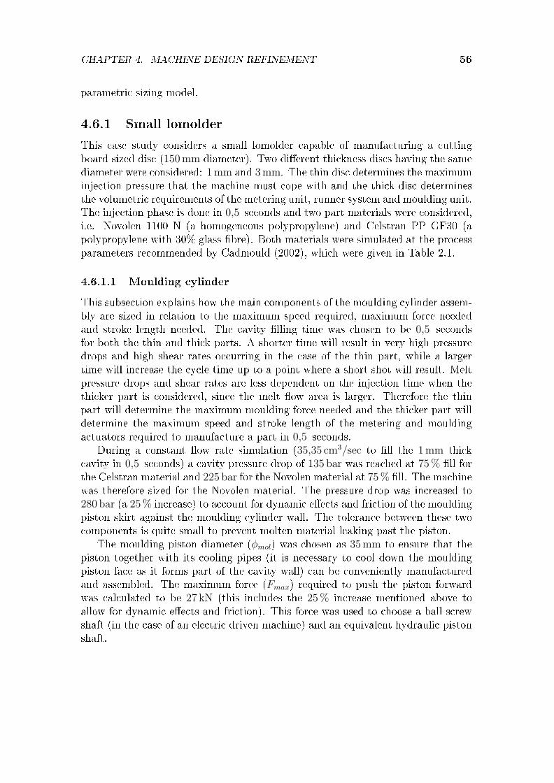
CHAPTER 4. MACHINE DESIGN REFINEMENT 56
parametric sizing model.
4.6.1 Small lomolder
This case study considers a small lomolder capable of manufacturing a cuttingboard sized disc (150mm diameter). Two di�erent thickness discs having the samediameter were considered: 1mm and 3mm. The thin disc determines the maximuminjection pressure that the machine must cope with and the thick disc determinesthe volumetric requirements of the metering unit, runner system and moulding unit.The injection phase is done in 0,5 seconds and two part materials were considered,i.e. Novolen 1100 N (a homogeneous polypropylene) and Celstran PP GF30 (apolypropylene with 30% glass �bre). Both materials were simulated at the processparameters recommended by Cadmould (2002), which were given in Table 2.1.
4.6.1.1 Moulding cylinder
This subsection explains how the main components of the moulding cylinder assem-bly are sized in relation to the maximum speed required, maximum force neededand stroke length needed. The cavity �lling time was chosen to be 0,5 secondsfor both the thin and thick parts. A shorter time will result in very high pressuredrops and high shear rates occurring in the case of the thin part, while a largertime will increase the cycle time up to a point where a short shot will result. Meltpressure drops and shear rates are less dependent on the injection time when thethicker part is considered, since the melt �ow area is larger. Therefore the thinpart will determine the maximum moulding force needed and the thicker part willdetermine the maximum speed and stroke length of the metering and mouldingactuators required to manufacture a part in 0,5 seconds.
During a constant �ow rate simulation (35,35 cm3/sec to �ll the 1mm thickcavity in 0,5 seconds) a cavity pressure drop of 135 bar was reached at 75% �ll forthe Celstran material and 225 bar for the Novolen material at 75% �ll. The machinewas therefore sized for the Novolen material. The pressure drop was increased to280 bar (a 25% increase) to account for dynamic e�ects and friction of the mouldingpiston skirt against the moulding cylinder wall. The tolerance between these twocomponents is quite small to prevent molten material leaking past the piston.
The moulding piston diameter (φmol) was chosen as 35mm to ensure that thepiston together with its cooling pipes (it is necessary to cool down the mouldingpiston face as it forms part of the cavity wall) can be conveniently manufacturedand assembled. The maximum force (Fmax) required to push the piston forwardwas calculated to be 27 kN (this includes the 25% increase mentioned above toallow for dynamic e�ects and friction). This force was used to choose a ball screwshaft (in the case of an electric driven machine) and an equivalent hydraulic pistonshaft.

CHAPTER 4. MACHINE DESIGN REFINEMENT 57
In order to �ll the smaller cavity size in 0,5 seconds, an average mouldingpiston speed of 37mm/sec (during the �rst 75% of cavity �lling) was necessarywhen calculated on a volume basis and assuming that no material is pushed intothe cavity by the metering piston.
Focussing on the thicker disc of 3mm, a pressure of only 40 bar is needed to �llthe cavity completely (i.e. no constant pressure injection phase will be required) ata constant �ow rate of 106 cm3/sec in 0,5 seconds for the Novolen material. TheCelstran material gives a cavity pressure drop of 30 bar for the same conditions.In this example machine sizing was done for a constant melt �ow rate up to thepoint where the cavity is 100% �lled (refer to Figure 4.2a). Thus 40 bar (the higherpressure drop is taken for machine sizing) must be delivered by the piston actuatorat a speed of 106mm/sec. This pressure drop of 40 bar relates to a piston force of3,8 kN. Lower requirements will result if the �ow rate diagram of Figure 4.2b isused.
Therefore machine sizing (servo-electric motor and accompanying pulley/beltassembly if necessary or hydraulic power pack) has to be done for these sizingthresholds:
� 37mm/sec at a force of 27 kN (1mm thick disc requirement)
� 106mm/sec at a force of 3,8 kN for a distance of 55mm (3mm thick discrequirement)
4.6.1.2 Metering cylinder
Measurement accuracy is an important factor when choosing a diameter for themetering piston. A larger diameter will require a better encoding accuracy on thecontrol side, while a smaller diameter will require a longer metering cylinder. Adiameter of 30mm was chosen for the metering piston. This is due to manufacturingconstraints and assembly convenience. It is less than the moulding piston diameter,since no cooling of the metering piston face is required. Therefore the meteringpiston must be able to travel 75mm, which was increased to 80mm for designsafety to be able to manufacture the thicker part.
The distance swept by the moulding piston (i.e. the distance from the startof the melt fed port to the ring gate) is 72mm in this machine con�guration asdetermined by the parametric sizing model. This swept volume is larger than theshot volume required for the thick part. This means that no mould �lling is doneby the metering piston and the metering pressure drop is equal to the pressure dropoccurring as the material �ows in the runners. The metering cylinder is designedfor a pressure drop of 150 bar to be able to transport the molten material in front ofthe moulding piston through the runner system (shown in Figure 4.4) in the sametime as the mould �lling time, i.e. 0,5 seconds. This pressure is chosen by the userand takes into account dynamic e�ects and the friction of the piston sleeve against

CHAPTER 4. MACHINE DESIGN REFINEMENT 58
the metering cylinder wall (with metering this tolerance is equally important, sinceany leakage will have a negative impact on the measuring accuracy). The meteringactuator is rather over-sized in this scenario to ensure that the metering phase timewill be reached. Therefore, no part defects will occur as a result of premature meltsolidi�cation in the moulding cylinder as the metering transfer time will be shortenough to ensure a good part quality.
The maximum force on the metering piston was 10,6 kN and this force wasagain used to size the shaft of the actuating device (either hydraulic or electric)against buckling and fatigue. The maximum metering piston speed was calculatedto be 150mm/sec and this speed was again used to size the hydraulic power packor servo motor drive. In order to do a costing analysis, di�erent combinations ofservo motors and belt/pulley drives, or hydraulic systems, are compared to �nd theoptimum solution (Chapter 5).
4.6.1.3 Runner �ow areas
The critical �ow areas are discussed for the Novolen material in this section asthe calculations are similar for the Celstran material. The pressure gradient ofthe material (Novolen which gives a higher pressure gradient than Celstran) at theentry to the cavity is 237 bar/m (for the 1mm thick part which is higher than thepressure gradient for the 3mm thick part), as calculated by Richardson's equationfor �ow between parallel plates (Equation 4.4.2). The channel width (w) was takenas the circumference of the moulding piston and the half-height (h) as half of thepart thickness.
The pressure gradient of the melt �ow in the moulding cylinder is 2,5 bar/mfor �ow in round tubes (Equation 4.4.1). For the metering cylinder this pressuregradient is equal to 3,5 bar/m as a result from the smaller diameter piston. Theserespective pressure gradients are much smaller than the limiting 237 bar/m and thisis expected, since the chosen diameters of both cylinders were limited to fairly largevalues by manufacturing constraints. Keep in mind that these pressure gradientsare not very accurate, since the requirements of Richardson's formulae (a fullydeveloped velocity �eld) are generally not met due to the short distance of the�ow geometry. However, it is noted that the predicted pressure gradients are inthe order of ten times smaller than the critical limiting value. Therefore, it can beargued that the pressure gradient restriction is still met.
The semi-annular runner (Figure 4.5 and 4.8) was analysed with both of Richard-son's equations. The highest pressure gradient was compared to the material pres-sure gradient at the cavity entry. The equivalent channel height (2h) was equal to10mm and the channel width (w) was taken to be 62mm, i.e. the arc distance be-tween the centres of the two R6 radii. These channel dimensions lead to a pressuregradient of 10,9 bar/m when Equation 4.4.2 is used. The hydraulic diameter of thisrunner computes to 17,9mm. This gives a pressure gradient of 10,6 bar/m when

CHAPTER 4. MACHINE DESIGN REFINEMENT 59
54◦
R6
φ53
φ45
Figure 4.8: Semi-annular runner dimensions
15◦
15 53◦
Figure 4.9: Moulding cylinder dimensions
Equation 4.4.1 is used for �ow in tubes. Both these calculated pressure gradientsare well below the limit of 237 bar/m and therefore the channel semi-annular runnerdimensions are satisfactory.
The moulding cylinder's two ports were analysed by halving the material �owrate (Q) and calculating the dimensions of one hole (refer to Figure 4.9). Sincethese ports are almost circular it would not make sense to use Richardson's �owbetween parallel plates formula. The hydraulic diameter of the ports computes to16,2mm and this gives a pressure gradient of 10 bar/m which is also well inside the237 bar/m barrier. Therefore all the �ow areas conform to the principle of havingthe largest pressure gradient at the point where the molten material enters thecavity.

CHAPTER 4. MACHINE DESIGN REFINEMENT 60
4.6.2 Large lomolder
As a second case study, a large lomolder unit's dimensions are considered. Sincethe calculations are similar to that in the previous section, this section will focus onthe di�erences between the small and large lomolder and point out speci�c pitfalls.The large lomolder is a machine capable of manufacturing a plastic pallet (± 20Lvolume) used in the transporting business. The same two polymers as for the smalllomolder were used for the calculations in this section.
4.6.2.1 Moulding and metering cylinders
The plastic pallet has a projected area of 1,0m2. Typical wall thickness varies from3mm to 6mm. To �ll such a large cavity with only one moulding cylinder in atypical �ll time of 3 seconds, will result in high cavity pressure drops (in the orderof 300 bar for the thin wall sections at 75% �ll). This calculation was done with amoulding piston diameter of 252mm. This diameter value was calculated in such away that the moulding piston frontal area is 5% of the part e�ective area. This 5%area ratio was suggested in a European patent (Eckardt and Stemke, 2000) as idealin order to lower the cavity injection pressures (case studies in Chapter 5 describein detail how this area ratio in�uences the injection pressure drop).
The cavity pressure drop of 300 bar and the moulding piston diameter of 252mmlead to a very high calculated axial force (1867 kN) for the moulding piston shaftactuator (either hydraulic or electric). In this calculation a 25% increase in pressuredrop was allowed for unknowns such as dynamic e�ects and friction. It was found tobe impossible to drive this piston with an electric servo motor and ball screw shaft,since it is beyond the capabilities of currently available servomotors. On the otherhand, it would be very expensive to build a hydraulic actuator with accompanyingpower pack to move such a large piston under such high loads.
A possible solution to this problem is to design the piston moulding machinewith more than one moulding cylinder. Di�erent con�gurations are possible withfour or even nine moulding pistons. Each moulding piston can have its own meteringunit attached or metering units can be shared. The injection cavity pressure dropdrops to about 120 bar (at 75% �ll) when four moulding cylinders are used for cavity�lling (these moulding cylinder diameters are also sized to the 5% area ratio). Partdesign will obviously play an important role when more than one moulding cylinderis used as weld lines (the position where two melt fronts reach each other duringthe �lling process) will form in the part. This is even more important when �bresare used, since the �bres will not cross over the weld lines. This phenomenoncan drastically in�uence the strength of a part if the weld lines are not correctlypositioned in the part. Multi lomolding unit �lling is discussed as a case study inChapter 6.
CHAPTER 4. MACHINE DESIGN REFINEMENT 61
Costing decisions can be determined once the di�erent costs are known for eachcon�guration. Chapter 5 gives insight into the costs involved in the single piston de-sign con�guration. Spatial- and assembly constraints are important considerations.The metering cylinder con�gurations will be in�uenced by the required measuringaccuracy. More metering cylinders may provide better metering accuracy, but themeasuring volume error may well be less signi�cant on such a large part whencompared to a smaller part. Part defects as a result of inaccurate metering werediscussed in Section 3.2.
4.6.2.2 Flow areas required
The calculations of the �ow areas showed that all of these areas can easily bechosen to satisfy the maximum pressure gradient threshold as discussed in thesmall lomolder case study. One of the big design di�erences is the thicker stationaryplaten (it can be up to one metre thick for such a large part) on the larger machine.This leads to a proportionally longer semi-annular runner (refer to Figure 4.4) thanrequired for the smaller lomolder.
4.7 Conclusion
Chapter 3 explained various machine concepts and evaluations were given for theirsuitability as candidates for further design development. In this chapter, the chosenconcept was further developed and a parametric machine model created to assistin layout design. Di�erent component material choices were highlighted.
This chapter described the parametric machine design model for the lomoldingunits of a piston moulding machine. Key aspects (material runner design, meteringand moulding unit forces, stroke lengths and piston speeds) regarding the designof the machine were highlighted.
The user provides inputs to the semi-analytical model (Chapter 2) regardingpart dimensions, material properties and process parameters. The semi-analyticalmodel uses this information to calculate the cavity pressure drop required to �ll themould. Once this step is completed, the parametric model uses this information tocalculate the required material �ow areas, forces on the piston actuators, requiredpiston speeds and required piston stroke lengths.
This parametric design information is then used to size either the electric orhydraulic actuators needed. The true value of the parametric model comes forth asit supplies the user with a machine layout design with very little user input. Thisparametric model therefore enables thorough machine optimisation as it allows adesigner to quickly compare a large number of design options.

CHAPTER 4. MACHINE DESIGN REFINEMENT 62
The parametric model was applied to two case studies to show the versatilityof designing machines at extreme ends. It is an essential element in predicting costfor the piston moulding machines.

Chapter 5
Parametric Cost Model
5.1 Introduction
This chapter describes a method to approximately determine the purchase cost ofa lomolding unit (i.e. metering unit, moulding unit and melt transfer runners).Brief consideration is also given to the maintenance- and operating cost of theseunits. Focus is placed on the small and large lomolders discussed in Chapter 4 anda medium sized lomolder is also analysed. All prices obtained at the end of 2006and beginning of 2007 do not include value added tax (VAT). It is noted that thesecosts are intended for di�erent machine design cost evaluation and not for quotingpurposes. As in the previous chapters, the subsystems of a lomolding machine alsofound in injection moulders, e.g. the clamping unit, are not considered here.
Figure 5.1 (Blanchard and Fabrycky, 1997) shows where life cycle cost �ts intothe value that is added by di�erent levels of design consideration. As can be seenfrom the �gure the life cycle cost elements considered in this study cover only asmall percentage of the overall picture. However, speci�cally in the case of the SouthAfrican market, these are typical costs that are mainly considered by companies indecisions about purchasing machines.
The following key design decisions in�uence the purchase cost of machine com-ponents considerably:
� The frontal area of the moulding piston face compared to the e�ective areaof the part strongly in�uences cavity pressure and the related injection force.This is discussed in Section 5.2.
� The choice between hydraulic and servo electric actuators. Advantages ofboth will be highlighted in the sections that follow.
� The choice between one and multiple lomolding units per part which becomesrelevant when large parts are manufactured. This aspect is discussed as a casestudy in Chapter 6.
63
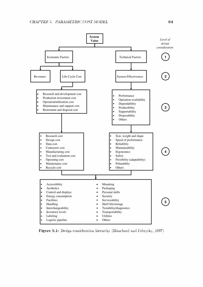
CHAPTER 5. PARAMETRIC COST MODEL 64
SystemValue
Economic Factors Technical Factors
Revenues Life-Cycle Cost System Effectiveness
� Research and development cost� Production investment cost� Operation/utilisation cost� Maintenance and support cost� Retirement and disposal cost
� Performance� Operation availability� Dependability� Producibility� Supportability� Disposability� Others
� Research cost� Design cost� Data cost� Contractor cost� Manufacturing cost� Test and evaluation cost� Operating cost� Maintenance cost� Recycle cost
� Size, weight and shape� Speed of performance� Reliability� Maintainability� Ergonomics� Safety� Flexibility (adaptability)� Polutability� Others
� Accessibility� Aesthetics� Control and displays� Energy consumption� Facilities� Handling� Interchangeability� Inventory levels� Labeling� Logistic pipeline
� Mounting� Packaging� Personal skills� Security� Serviceability� Shelf life/storage� Testability/diagnostics� Transportability� Utilities� Others
1
Level ofdesign
consideration
2
3
4
5
Figure 5.1: Design consideration hierarchy (Blanchard and Fabrycky, 1997)

CHAPTER 5. PARAMETRIC COST MODEL 65
Choosing the type of actuator (hydraulic or electric) is not always driven bycost alone. This paragraph highlights the di�erences between hydraulic and electricactuators and where one will be chosen above the other for certain reasons. Servoelectric con�gurations are more accurately controlled than hydraulics. They aresuitable for clean environments (for instance food and beverages industries), sinceno oil leaks can develop over time. They are up to 40% more energy e�cientaccording to Bracke (2006). However, the control of hydraulic systems becomesincreasingly intelligent and thereby improving energy e�ciency. For instance theelectric motor driving the hydraulic pump can be speed controlled to supply �owonly when power is needed.
Electric con�gurations also o�er quieter working environments than their hy-draulic counterparts. Simultaneous actuation of the metering and moulding pistonsare easier to incorporate, since the electric system is easily simpli�ed in subsections,while it is more di�cult with hydraulics, where the power pack has to be upgradedwhen alterations resulting in exceeding the design pressure and �ow rate are needed.With an electric con�guration, only the relevant subsystem has to be replaced. Bet-ter part cycle times are generally obtained with electric machines (in the injectionmoulding industry). Fewer part rejects are manufactured with electric machines,as a result of the better accuracy and better repeatability (no oil heating time thata�ects both at start-up). Electric machines require less maintenance. However,their initial purchase cost is about on average 20% to 30% higher than that ofhydraulic systems (Bracke, 2006).
The possibility also exists to design a hybrid lomolder, where hydraulic actua-tion of the moulding piston where high forces are required is combined with electricactuation of the metering piston when high accuracy is required. The above para-graphs highlighted the considerations to be made when selecting a hydraulic orelectric con�guration for a speci�c application.
The e�ect of moulding piston face area to part e�ective area is discussed inthe next section. A detailed cost analysis of hydraulic actuation versus electricalactuation follows that. The costing of the custom lomolder manufactured parts isanalysed and this is followed by a brief discussion regarding control-, maintenance-and operating cost. Chapter 6 gives a design case study of a medium sized lomolderthat combines all the steps already described in the preceding chapters.
5.2 Moulding Piston to Part Area Ratio
The area ratio between the frontal area of the moulding piston face and the e�ectivearea of the moulded part is one of the most important machine sizing and costingfactors, since the melt injection force is driven by this relation. The e�ective area ofthe part is related to the aspect ratio (longest melt �ow path divided by the averagethickness of the �ow path) of the part. A good approximation is to take it equal

CHAPTER 5. PARAMETRIC COST MODEL 66
to the volume of the part divided by the average part thickness. It is noted thatthe part projected area in the direction of the platens is used to size the clampingunit.
The area ratio trade-o� positions itself between having a long moulding pistonstroke (small diameter piston) and a short stroke with accompanying larger pistonface area. The area ratio is explored for hydraulic and electric actuators on apurchase cost basis as well as a manufacturing constraints basis. Three sizes oflomolders are considered: a small lomolder capable of manufacturing a φ15 cmdisc (breadboard size), a medium sized lomolder that can produce a φ50 cm disc(serving tray size) and a large lomolder capable of manufacturing a 1m2 squareplate (transport palette size). Two typical part thicknesses are considered for eachpart size. Speci�cations of the di�erent part sizes are given in Table 5.1.
Advantages of a small diameter piston include:
� The volume swept by the moulding piston becomes small enough to requirethat the metering piston inject some of the melt into the cavity during themelt transfer phase. This decreases the cycle time per part and shortens thetime that the melt is in contact with the cold cylinder wall near the ring gate(minimising potential solidi�cation problems mentioned in Chapter 4).
� The moulding piston force required reduces as the face area decreases. How-ever, a trade-o� exists as the longer actuator shaft is more costly. Shaftbuckling becomes a factor as well as the speed limitations on the hydraulicseals (±1m/s) or the precision screw nut (function of screw and nut size -discussed in Section 5.4). Advantages include smaller sized actuators, smallerservo motors (pulleys and belts as well) or hydraulic power packs.
� A smaller sized hole in the stationary platen is an advantage, since the platenis weakened less at the position of maximum cavity pressure drop as discussedin Chapter 4. This also means that more space is available for the part ejectionsystem.
Disadvantages of a small diameter piston include:
� Cooling of the moulding piston becomes more di�cult as the space for thecooling pipes is decreased. The length of these pipes also increases and there-fore the pipes become more costly. As the pipe length increases, the water�ow pressure drop across the pipe length also increases.
� A smaller diameter face will result in a higher melt shear rate at the ringgate.
� A larger diameter piston will hide an error in melt volume measurement betteras the extra/lack of material will result in a thinner extension/indent on/inthe part (refer to Figure 3.2).

CHAPTER 5. PARAMETRIC COST MODEL 67
0 5 10 15 20 250
200
400
600
800
Maximum clamp force and actuator force[kN]
Area ratio [%]0 5 10 15 20 25
60
80
100
120
140
Maximum pressure drop [bar]
Max clamp forceMax ∆PMax actuator force
Figure 5.2: Piston area in�uence on cavity pressure drop, clamp force and actuator force
The piston face area also plays an important role in the metering cylinder. Asmaller diameter piston will result in a longer actuator shaft (increased cost), butthe metering accuracy will be improved.
Table 5.1: Range of lomolder units investigated
Mini LM Midi LM Maxi LMPart type φ15 cm disc φ50 cm disc 1 m2 square plate
Part e�ective area [cm2] 176,7 1963,5 10 000Thin part thickness [mm] 1 2 3Thick part thickness [mm] 3 4 6Thin part volume [cm3] 17,67 392,7 3000Thick part volume [cm3] 53,01 785,4 6000
Injection time [sec] 0,5 1 3
Figure 5.2 show the typical in�uence of the ratio of piston face area to parte�ective area on the injection pressure drop, clamp force required and injection forcerequired. The graph shows Cadmould results for the Celstran material (materialproperties given in Table 2.1) injected into a disc cavity of 500mm in diameter and3mm thick. Injection is done in 1 second and the values are calculated when thecavity is completely �lled at a constant �ll rate.

CHAPTER 5. PARAMETRIC COST MODEL 68
Figure 5.2 shows a 17% drop in the total cavity pressure drop in the area ratiorange of 0% to 5%. From an area ratio of 5% onwards, the advantage of thedecrease in pressure drop is less rewarding considering the increase in actuatorforce required to push the melt into the cavity. Figure 5.2 shows that the clampingforce required to prevent opening of the moulding platens is less dependent on thearea ratio. A clamping force drop of 9,1% is noted over the range of area ratiosconsidered.
It is necessary to know the piston to part area ratio in order to calculate thepurchase cost of a certain con�guration machine. However, this area ratio is veryvaguely de�ned by Eckardt and Stemke (2000). They explored ratios from 0,5% to5% and never came to a conclusion of what will be an optimum ratio or if there isone. The next part of this section will explain a route that the author investigatedto determine a good estimate (based on lomolder unit purchase cost and physicalconstraints) of area ratios for di�erent sizes of lomolder units.
First of all it is necessary to de�ne the range of lomolders considered in thisstudy. Table 5.1 shows properties of the di�erent sizes of lomolders considered. Twotypes of parts are considered: round and rectangular. Di�erent thickness parts areconsidered for the following reasons:
� A thin part leads to a higher cavity pressure drop. This determines theinjection force required from the actuators as well as the power rating of thehydraulic power pack or servo electric motors.
� A thick part determines the volume of the part and therefore the injectionstroke required by the metering cylinder actuators.
The same melt injection time is used in both part thickness cases for the threeranges of lomolders considered. These times are comparable to typical injectiontimes if the parts are made with injection moulding machines. The larger volumepart (thicker part) can be injected in the same time as the thin part, as the pressuredrop across the cavity is much less as a result of the larger �ow area available.Therefore a higher injection speed can be used, but keeping the higher materialshear rates in mind. The Novolen material is taken as reference material to calculatethe cavity pressure drop, since it gives a higher pressure drop than the Celstranmaterial. The melt inlet temperature is 220� and the cavity wall temperature40�. The parts are cooled to 120� and ejected.
Table 5.2 shows the following information for the mini, midi and maxi lomoldercon�gurations. The labels thin and thick refer to the part thickness in each case.
� a range of ratios of moulding piston face area to part e�ective area that wasselected for consideration
� the moulding piston diameter was calculated from the area ratio

CHAPTER 5. PARAMETRIC COST MODEL 69
Table 5.2: Lomolder design data
Mini LomolderArea ratio Piston dia ∆P Piston force Piston stroke Piston speed
[%] [mm] [bar] [kN] [mm] [mm/sec]thin thick thin thick
0,5 10,6 280 2,5 200 600 400 12001,0 15,0 271 4,8 100 300 200 6002,0 21,2 256 9,0 50 150 100 3003,0 26,0 247 13,1 33 100 67 2005,0 33,5 230 20,3 20 60 40 1207,0 39,7 215 26,6 14 43 29 8610,0 47,4 196 34,9 10 30 20 60
Midi Lomolder0,5 35,4 352 34,6 400 800 400 8001,0 50,0 341 66,9 200 400 200 4002,0 70,7 326 127,9 100 200 100 2003,0 86,6 312 184,0 67 133 67 1335,0 111,8 292 286,7 40 80 40 807,0 132,3 278 381,4 29 57 29 5710,0 158,1 257 504,7 20 40 20 40
Maxi Lomolder0,5 79,8 448 224 600 1200 200 4001,0 112,8 433 433 300 600 100 2002,0 159,6 416 833 150 300 50 1003,0 195,4 399 1197 100 200 33 675,0 252,3 373 1867 60 120 20 407,0 298,5 355 2488 43 86 14 2910,0 356,8 328 3284 30 60 10 20
� the cavity pressure drop as calculated by Cadmould at 75% part �ll multipliedby 1,25 to account for uncertainties as mentioned in Chapter 4
� the force on the piston face as a result of the pressure drop
� the required piston stroke, determined from the shot volume
� the required piston speed to �ll the cavity in the time speci�ed in Table 5.1
5.3 Hydraulic Actuation for Moulding Cylinder
This section describes the di�erent costs associated with the di�erent lomoldersstudied. Most (70% to 80%) of the hydraulic system cost is contributed by thecylinder, hydraulic pump and electric motor cost. Focus is placed on these threecost elements, since the rest of the hydraulic system cost is dependent on clientcon�guration, control requirements and so forth.

CHAPTER 5. PARAMETRIC COST MODEL 70
Two choices are available when it comes to selecting a power pack con�guration:�xed and variable displacement pump solutions. The �xed displacement pump isdriven by an AC electric motor at constant speed (usually at 1450 rpm). The sys-tem will provide pressure (normally 250 bar) up to a certain maximum �ow rate.When this �ow rate is exceeded, the pressure generated by the pump will drop. Ahydraulic pressure control valve ensures that the pressure will not rise higher thana certain safety preset value. If this preset value is reached, the excess hydraulic oilis bypassed to the tank by a pressure release valve, to keep the pressure constant.This method of pressure regulation generates heat that has to be removed from theoil again and is not favourable. However, this system option is available in smallersizes than the variable displacement pump solution. It is costly to achieve the sameversatility as that of the variable displacement pump solution. More valves and ac-cumulators can be added to the �xed displacement pump solution, but this increasesthe total hydraulic system cost and complexity. Over time it will cost as much asthe variable displacement pump solution to maintain, as a result of the complexity.Therefore, the author decided to opt for the variable displacement pump solution,even if it is oversized in the case of the mini lomolder. It is realised that manydi�erent combinations of pumps, motors, actuators, accumulators, valves and con-trol con�gurations can be used in a lomolder. The variable pump con�guration isexplored as a basis to which other combinations can be compared if necessary. Thiscomparison falls outside the scope of this research.
With the variable displacement pump solution, the generated pressure in thesystem is measured and the motor speed adjusted to keep the pressure constant at apreset value. The AC motor will reach a maximum speed at a certain required �owrate and this is the upper limit of the system. Thereafter, the generated pressurewill drop. A pressure relief valve is also included in this system for safety reasons.The pressure limits are preset beforehand. This system option lends itself to easyexpansion and producing parts with varying volumes. Small accumulators are also�tted occasionally to these variable displacement pump solutions to even out oil�ow spikes that may occur.
From the data presented in Table 5.2, the hydraulic equipment is selected asfollows: Hydraulic cylinder tubing comes in standard diameters - 40mm, 63mm,80mm, 100mm, 125mm, 160mm, 200mm and 250mm. Special sizes can be man-ufactured, but the costs involved are about three to four times more than that ofthe nearest available diameter. Hydraulic power packs usually deliver pressure at250 bar as an industry standard. For each size cylinder a maximum force can becalculated according to equation 5.3.1.
F = pA (5.3.1)
where F is the force, p is the pressure and A is the area of the cylinder. Theforce generated by the hydraulic cylinder must just be higher that the force required

CHAPTER 5. PARAMETRIC COST MODEL 71
by the moulding cylinder in Table 5.2. Once the cylinder size is selected, thehydraulic �ow rate can be calculated, since the injection time, cylinder area andpiston stroke (determined by the thickest part i.e. highest volume) are known.A hydraulic pump can then be selected on the same basis as the cylinders. Thesmallest pump that satis�es the �ow rate requirement of the system is selected. Thevariable displacement pumps have e�ciencies of 94%. The motor size is selectedby calculating the power required as given in equation 5.3.2. The four pole 50Hzelectric motors run at 1450 rpm and have e�ciencies of 80%. The highest of the twopower requirements as prescribed by the thin or thick part are used. The pumpsand motors are selected by dividing the required �ow and power by their respectivee�ciencies. Since the melt cavity pressure drop is already increased to account forunknowns, the motor size is not further adjusted.
P = pQ = Fv (5.3.2)
where P is the power required, p is the pressure, Q is the hydraulic �ow rate, F isthe piston force and v is the piston speed. Table 5.3 shows the hardware selectionsfor the di�erent area ratios and Table 5.4 gives the corresponding cost estimates.The cylinder stroke is prescribed by the thickest part (highest volume). The electricmotor power is driven by the thin part as it generates the higher pressure drop.It is noted that the combination of the longer stroke (and therefore higher oil �owrate to manufacture the thicker part in the same time as the thin part) and thehigher force required to manufacture the thin part is not used to size the electricmotor needed to drive the hydraulic pump. The thicker part requires less force toproduce a part as discussed before. Normally the power requirement is higher forthe thinner part as a result of the large increase in force required.
From Table 5.3 (refer to Table A.1 in Appendix A) it can be seen that thesmallest motor size (3 kW) satis�es the requirements of all the cases of the minilomolder. The smallest standard hydraulic cylinder diameter (40mm - Figure A.4)satis�es all the corresponding cases except the one with the area ratio of 10%.This is the reason that a larger hydraulic pump is necessary for the �rst two cases(higher required volume), since the required piston stroke decreases as the arearatio increases.
The midi lomolder cases are not restricted by hydraulic cylinder diameter, elec-tric motor size or hydraulic pump �ow rate. Therefore, no extreme values exist asin the case of the mini lomolder.
The maxi lomolder requires larger diameter cylinders than available in the stan-dard range for the last three cases. This result in custom made cylinders which areexpensive as can be seen in Table 5.4 for area ratios 5,0%, 7,0% and 10,0%.

CHAPTER 5. PARAMETRIC COST MODEL 72
Table 5.3: Lomolder hydraulic selection
Mini LomolderArea ratio Cylinder dia Cylinder stroke Pump �ow rate Power rating
[%] [mm] [mm] [cc/rev] [kW]0,5 40 600 71 3,01,0 40 300 45 3,02,0 40 150 18 3,03,0 40 100 18 3,05,0 40 60 18 3,07,0 40 43 18 3,010,0 50 30 18 3,0
Midi Lomolder0,5 63 800 125 18,51,0 80 400 125 18,52,0 100 200 71 18,53,0 100 133 71 18,55,0 125 80 45 18,57,0 160 57 71 15,010,0 160 40 45 15,0
Maxi Lomolder0,5 125 1200 250 75,01,0 160 600 180 75,02,0 250 300 180 55,03,0 250 200 180 55,05,0 320 120 180 55,07,0 380 86 180 55,010,0 420 60 125 45,0
5.4 Electric Actuation for Moulding Cylinder
Selecting a servo motor - ballscrew con�guration is a bit trickier than for the hy-draulic counterpart. First of all a screw is selected that is able to handle theforce/speed requirements of the con�guration. A matching servo motor is thenadded to the system that will deliver the necessary torque. The speed is not asimportant, except that a maximum exists for the motor as well as the screw. Apulley/belt con�guration is required even if the speed range of the servo motor iswell matched to that required by the system, since the ballscrew nut is turned inall con�gurations. The lomolder con�gurations have varying speeds and loads andtherefore the average load the screw will see in its service life is given by equa-tion 5.4.1. Equations 5.4.1 to 5.4.5 comes from a manual by the Rexroth BoschGroup (2002).
Fm = 3
√F 3
1
n1
nm
q1
100+ F 3
2
n2
nm
q2
100+ ... + F 3
n
nn
nm
qn
100(5.4.1)
where the average speed is given by equation 5.4.2:

CHAPTER 5. PARAMETRIC COST MODEL 73
Table 5.4: Lomolder hydraulic system costs
Mini LomolderArea ratio Cylinder cost Motor cost Pump cost Total cost
[%] [R] [R] [R] [R]0,5 3724 2208 59 187 65 1181,0 3514 2208 51 789 57 5112,0 3409 2208 42 222 47 8393,0 3374 2208 42 222 47 8045,0 3346 2208 42 222 47 7767,0 3334 2208 42 222 47 76410,0 3439 2208 42 222 47 870
Midi Lomolder0,5 4794 8966 127 225 140 9851,0 5747 8966 127 225 141 9382,0 6301 8966 59 187 74 4533,0 6134 8966 59 187 74 2875,0 8972 8966 51 789 69 7277,0 11 608 7302 59 187 78 09610,0 11 510 7302 51 789 70 601
Maxi Lomolder0,5 13 161 28 450 176 403 218 0141,0 14 702 28 450 140 317 183 4692,0 28 386 23 376 140 317 192 0793,0 27 060 23 376 140 317 190 7535,0 85 240 23 376 140 317 248 9337,0 172 545 23 376 140 317 336 23810,0 188 980 18 952 127 225 335 157
nm =q1
100n1 +
q2
100n2 + ... +
qn
100nn (5.4.2)
where qi is a percentage of the time that the screw will operate at a certainspeed (ni). The average speed (nm) is in�uenced by the lead of the screw, but theaverage load is not.
The di�erent lomolder screws were chosen to last for two years under continuousoperation. This choice was made as Bracke (2006) mentioned that Engel's electricinjection moulding machines requires service/replacement of its ballscrews everytwo years on average. The accuracy of the ballscrews becomes less as more play inthe screw/nut develops as a result of wear over time. From this the service life inhours (Lh) and the service life in revolutions (L) can be calculated:
L = 60nmLh (5.4.3)
The dynamic load rating (C) is calculated as in equation 5.4.4 and from thisthe screw is selected from a catalogue.

CHAPTER 5. PARAMETRIC COST MODEL 74
@@
@@R
nuthousing
?
load bearingelement �
��
���
thrustbearing
?
Spiraconroller screw
������
roller
6
needleroller bearing
@@
@@I
wiper seal
Figure 5.3: Roller screw (Spiracon, 2007)
C = Fm3
√L
106(5.4.4)
If more than one screw with di�erent leads satisfy the dynamic load rate require-ment, then the one with the smallest lead will often be selected, since this will lowerthe torque requirements (T ) of the servo drive as calculated in equation 5.4.5. Theoperating rotational speed of the screw must not exceed its safe operating speed,or else a screw with a higher lead has to be selected.
T =Fp
2πη(5.4.5)
where F is the operating load, p is the screw lead and η is the screw mechanicale�ciency (normally in the range of 90% for Bosch Rexroth ballscrews). Once againthe lomolder cases presented here has relatively short strokes and therefore screwbuckling did not present any problems. Bosch Rexroth manufactures screws withmainly a 10mm or 20mm lead. From their catalogue screws could be selected forthe mini lomolder dynamic load requirements, as well as the �rst two area ratio casesof the midi lomolder. However, the company stopped manufacturing their highestdynamic load rating range, since it is very expensive and not often requested byclients. The reason for the high cost is that a grinding process is necessary in thecase of the large screws/balls assemblies to achieve a good tolerance. The smallerassemblies' components are rolled.

CHAPTER 5. PARAMETRIC COST MODEL 75
The author explored roller screws (Figure 5.3) as a good alternative to ballscrews when high dynamic load ratings are required. These screws were distributedby Yale Engineering products, but they stopped producing them due to high costsand low sales volume. SKF still distributes similar screws to Yale Engineering inSouth Africa. These screws have a short roller screw that runs on a few consecutivethreads in place of the balls of the ball screw. Their higher cost (compared toballscrews) is o�set by the following advantages:
� higher dynamic load capacity
� larger diameters and higher leads
� higher positional accuracy
� longer life
� higher sti�ness
� higher speed and acceleration
� low temperature operation
� lower noise
� nut easily removed with rollers retained
These roller screws have the capabilities required by all of the midi lomoldercases as well as the �rst two area ratio cases of the maxi lomolder. However, it willbe seen that current available servo motors are only able to drive screws up to the�rst two cases of the midi lomolder con�guration. Therefore, these screws will playa role when higher torque servo motors come to the market in future.
Ballscrews are used in this study, since they are cheaper and their accuracycan be improved by current feedback control technology. The selected lomolderballscrews, screw costs, nut costs, servo motor costs and drive costs are shown inTables 5.5 and 5.6 for the mini and midi lomolder con�gurations. It can be seenfrom Table 5.6 that the motor and drive cost shadows the screw and nut costsby about a factor of 10 across the range of area ratios for the mini- and midilomolders. A screw cannot be selected for the mini lomolder case at the 0,5% arearatio. The reason is that the rotational speed is higher than the allowed safe speedfor the screw and nut combination. At such speeds excessive friction occurs at theball bearings and screw contact area. The large amount of generated heat cannotbe conducted quickly enough and this leads to lubrication failure and nut seizure.Therefore, no costs were calculated for this area ratio mini lomolder case.

CHAPTER 5. PARAMETRIC COST MODEL 76
Table 5.5: Lomolder screw and motor selection
Mini LomolderArea Stroke Screw Rotational Torque Selectedratio lead speed required screw[%] [mm] [mm] [rpm] [Nm] [#]0,5 600 20 3600 - Rotational speed too high1,0 300 20 1800 15,6 32x20Rx3.969-22,0 150 10 1800 14,8 32x10Rx3.969-53,0 100 10 1200 21,3 32x10Rx3.969-55,0 60 10 720 33,1 40x10Rx6-47,0 43 10 516 43,1 40x10Rx6-410,0 30 10 360 56,4 40x10Rx6-4
Midi Lomolder0,5 800 20 2400 112,7 50x20Rx6.5-31,0 400 10 2400 108,8 63x10Rx6-6
The selected servo motors for the mini lomolder cases are all standard servomotors. The midi lomolder cases require asynchronous AC motors that can be con-trolled to operate as a servo motor and drive combination. It is more expensive, butcan deliver higher torques that are required in these cases. If the client speci�callyrequests an electric con�guration for the higher torque requirement cases, a muchmore costly linear electric motor is available. Simply explained, these motors havea linear stator and the rotor rolls along the stator in a straight line. The high costis contributed by a special linear encoder, linear bearings and water cooled stator.The reason that the stator is water cooled is that a fan cannot be connected to itas in the normal servo motor case. These motors are extremely accurate and canhandle forces up to 20 tons.
The servo electric drives quoted in this section use absolute encoders, meaningthat their position is exactly known at any given time. Again, this was a choiceof the author and it is realised that less expensive incremental encoders couldhave been used. The absolute encoders o�ers the same versatility as the hydraulicvariable displacement pump con�guration and are therefore comparable on a costbasis. Incremental encoders use homing switches to calculate their position. Adisadvantage of the homing switches is that the servo drive has to be reset in caseof a power failure or system con�guration change. The total electric con�gurationcosts are shown in Table 5.6 for the mini and midi lomolder con�gurations. Thesecosts include all necessary power and communication cables.

CHAPTER 5. PARAMETRIC COST MODEL 77
Table 5.6: Lomolder electrical actuator costs
Mini LomolderArea Screw Nut Motor Drive Totalratio cost cost cost cost cost[%] [R] [R] [R] [R] [R]0,5 - - - - -1,0 1295 3333 15 030 27 342 47 0002,0 826 3158 15 030 27 342 46 3563,0 708 3158 17 712 27 342 48 9205,0 685 3690 21 969 27 342 53 6867,0 643 3690 22 725 38 334 65 39210,0 611 3690 27 289 38 334 69 924
Midi Lomolder0,5 3034 5097 38 696 47 877 94 7041,0 2429 5940 38 696 47 877 94 942
5.5 Comparison of Hydraulic and Electric
Actuation
5.5.1 Optimal area ratio
Optimal area ratios on a hardware purchase cost basis for the mini-, midi- andmaxi lomolder are derived in this subsection. It must be stressed that interpolationbetween di�erent area ratios to predict hardware cost is only a �rst approximation,since high non-linearities exist between these points.
From Table 5.4 it can be seen that an area ratio of 2,0% to 3,0% gives aminimum hydraulic purchase cost for the range of lomolder sizes analysed here.If cost is not the main design requirement, design outside of these regions arepossible, but the hardware limitations mentioned below must be kept in mind. Non-standard hardware are extremely expensive as it is made in small volumes wherestandard types of hardware are produced in series. Standard hydraulic cylinderseals can operate up to 1,0m/s. Larger speeds can be obtained, but special sealsand rod surface �nish requirements make this choice very expensive. Only the minilomolder's 0,5% area ratio requires a speed higher than 1,0m/s, but is discardedon a cost basis. Shaft buckling is not a problem in any of the analysed cases, sincethe rod lengths are relatively short in the 2,0% to 3,0% area ratio region and therods are well supported at the ends.
Area ratios of 2,0% to 3,0% provide a long enough stroke to work with regardingcontrol (discussed in Section 5.7) and may be changed to suite the client's needs. Forinstance, moulding against skins may require a larger piston diameter to decreasethe injection speed and decrease the shear rate as a result. In this case the arearatio is not selected with a minimum cost objective.
No conclusions regarding optimum piston to part area ratio can be obtained

CHAPTER 5. PARAMETRIC COST MODEL 78
0 2 4 6 8 100
50
100
150
200
250
300
350
Area ratio [%]
Total moulding actuator cost [R1000] Mini hydr
Midi hydrMaxi hydrMini elecMidi elec
Figure 5.4: Total moulding actuator cost for hydraulic and electric actuation
from the midi lomolder electrical case, since only two area ratio cases can be eval-uated with the components currently available in South Africa according to Venter(2007). Therefore, electric con�guration machines are limited to a 0,5% and 1,0%area ratio for the midi lomolder case. An area ratio of 2,0% to 3,0% is againfavourable on a purchase cost basis considering the mini lomolder electrical con�g-uration.
Thus, for both hydraulic and servo electric con�gurations it seems that a 2,0% to3,0% area ratio is good initial choice on a purchase cost view (refer to Figure 5.4).It is also noted that there is not much of a di�erence between the costs of thehydraulic and the electric con�gurations for the mini lomolder cases in the 2,0%to 3,0% area ratio range.
5.5.2 Metering actuator cost
For all three size lomolders, the hydraulic power pack is su�cient to drive themetering units. The reason is that only at the end of the moulding phase, maximumpiston force is needed. This force requirement determines the power pack size inthe cases considered here. Simultaneous actuation of the metering- and mouldingcylinders is not necessary in the lomolding con�guration, since the metering phaseis done during the part cooling and ejection phase. Therefore, only the cost of the

CHAPTER 5. PARAMETRIC COST MODEL 79
Table 5.7: Metering unit design data
Cylinder Actuator Injection Actuator Maximumdiameter stroke time speed force[mm] [mm] [sec] [mm/s] [kN]
Mini LM 30 75 0,5 150 13,3Midi LM 60 278 1,0 278 53,0Maxi LM 110 630 3,0 210 178,2
Table 5.8: Metering unit hydraulic con�guration cost
Cylinder Actuator Cylinderdiameter stroke cost[mm] [mm] [R]
Mini LM 40 75 3357Midi LM 63 278 4241Maxi LM 100 630 7376
cylinder has to be added to the total system cost. It must be kept in mind thatmould opening and part ejection actuation is not considered in the cost analysis.
Table 5.7 shows the design data for the actuators of the lomolder meteringcylinders. The forces are computed for a metering melt backpressure of 150 bar.The diameters of the cylinders were chosen to assist accurate metering, while thespeed limitations of the ball screws and hydraulic piston seals were kept in mind.Too large metering cylinder diameters will result in a short metering piston strokeand therefore better control encoder accuracy is required to measure the shot sizeaccurately. As the metering cylinder diameter is decreased, the total cylinder lengthincreases, resulting in a cost increase.
The mini lomolder metering cylinder has a diameter of 30mm, since it becomesvery di�cult to manufacture and assemble the unit if this diameter is further de-creased. It may be desirable to have the metering actuator stroke longer for themini lomolder case to achieve a good measuring accuracy. Since this is not possible,a more accurate position encoder may be needed for the mini lomolder meteringcylinder compared to the midi- and maxi lomolder cases. The hydraulic cylindercosts are given in Table 5.8. The cylinder cost is not as much in�uenced by thelength as the diameter and therefore its cost is mainly driven by the metering forcerequired to transfer the melt to the moulding cylinder. This force is very dependenton the area of the metering piston. A straight line is �tted through the three forceand cost points and equation 5.5.1 shows the relation:
Chydmet = 24.5Fmet + 2991.9 (5.5.1)
where Chydmet is the hydraulic metering unit cost and Fmet is the required me-tering piston force in kN. Figure A.1 in Appendix A shows the �t accuracy.

CHAPTER 5. PARAMETRIC COST MODEL 80
Table 5.9: Metering unit electric con�guration cost
Torque Nut Screw Servo motor Servo drive Totalrequired cost cost cost cost cost[Nm] [R] [R] [R] [R] [R]
Mini LM 23,5 2733 502 21 969 27 342 52 546Midi LM 93,7 5097 1251 38 696 47 877 92 921Maxi LM - - - - - -
Table 5.10: Moulding unit costs
Piston Total hydraulic Total electricforce cost cost[kN] [R] [R]
Mini LM 13,1 47 804 48 920Midi LM 184,0 74 287 94 942Maxi LM 1197,1 190 753 -
The electric con�guration cost is shown in Table 5.9. It is noted that thecosts are much higher, compared to the hydraulic actuation, since a servo motorand drive must also be included. Again, the maxi lomolder metering cylinderrequirements fall outside the range of currently available servo motors. A straightline (equation 5.5.2) is also used to interpolate for any electric metering cylinderbetween the mini and midi lomolder con�gurations. Care must be taken if thisequation is used outside the interpolated region.
Celecmet = 1017Fmet + 39020 (5.5.2)
where Celecmet is the electric metering actuator cost and Fmet is the requiredmetering piston force in kN. It is noted that equations 5.5.1 and 5.5.2 are derivedfor a metering cylinder melt backpressure of 150 bar. For other user de�ned back-pressures, these equations will be di�erent. The next step is to compute equationsfor the moulding cylinder actuators in a similar manner.
5.5.3 Moulding actuator cost vs. machine size
The costs in Table 5.10 are from Sections 5.3 and 5.4. All costs are for a piston topart area ratio of 3%, except the midi electrical moulding unit cost, which is for a1% area ratio, since the 3% area ratio is out of range.
Again a linear relationship (Equation 5.5.3) is assumed between the hydrauliccost data and the force required by the system.
Chydmol = 118.7Fmol + 49104 (5.5.3)

CHAPTER 5. PARAMETRIC COST MODEL 81
Table 5.11: Mini and maxi lomolder parts cost
Mass Material Manufacturing Assembly Totalcost cost cost cost
[kg] [R] [R] [R] [R]Mini LM 80 960 25 577 18 600 45 137Maxi LM 3343 40 116 42 541 41 920 124 577
where Chydmol is the hydraulic actuator cost for the moulding cylinder and Fmol
is the force on the moulding piston in kN. Figure A.2 in Appendix A shows the �taccuracy.
Equation 5.5.4 shows a linear relationship for the moulding cylinder actuation.It is noted that this equation is �tted for a moulding piston face area to parte�ective area ratio of 3,0% for a mini lomolder, but a 1,0% area ratio for a midilomolder. Therefore, this equation is not valid for moulding piston forces largerthan 66,9 kN (refer to Table 5.2).
Celecmol = 855.11Fmol + 37718 (5.5.4)
where Celecmol is the electric moulding actuator cost and Fmol is the requiredmoulding piston force in kN.
This concludes the costs involved for the metering and moulding actuators. Theequations developed in this chapter will be used to determine the cost of a mediumsized lomolder in Chapter 6.
5.6 Custom Manufactured Part Costs
This section describes the purchase cost of the manufactured parts for the lomolderassembly. These parts were designed before the cost analysis in the previous sec-tion was available. They were designed to withstand forces generated by a 5,0%moulding piston area to part area ratio con�guration. Therefore, these costs willnot be exceeded if the area ratio is reduced to a more optimum point as determinedearlier in this chapter.
The purchase cost of all the hardware that has to be manufactured (i.e. mould-ing unit, metering unit and runner system parts) is broken down into material cost,manufacturing cost and assembly cost. The parametric machine model (discussedin Chapter 4) was used to create layout designs for the mini, midi and maxi lo-molder. TF Design quoted for the manufacturing and assembly of the lomolderparts (see Appendix A for cost data). Table 5.11 shows the parts' cost for the miniand maxi lomolder con�gurations.
The parametric design model was used to generate parts for the midi lomolderas well. The accumulated mass of these parts amounted to 523 kg.

CHAPTER 5. PARAMETRIC COST MODEL 82
Table 5.12: Midi lomolder mass calculation and veri�cation
Produced Piston Mass ofpart volume force manufactured parts
[cm3] [kN] [kg]Mini LM 53 20 80Midi LM 785 287 523Maxi LM 6000 1867 3343
Table 5.12 shows the produced part volumes, piston forces (5% area ratio and75% cavity �ll multiplied by 1,25 ) and the total mass of the manufactured partsfor the three sizes of lomolders. The author explored whether a linear relationshipcould be found between the produced part volume, the required moulding pistonforce and the total mass of the lomolding unit's components. If such a relationshipexists, the lomolding unit component material cost can be estimated for any sizeof lomolder between the mini- and maxi lomolder limits.
The mass of the midi lomolder was linearly calculated on a part volume basis(mV ) as well as a force basis (mF ). The determined mass of the midi lomolder islisted below:
� determined by parametric sizing model: 523 kg
� linear interpolation by part volume (mV ): 482 kg
� linear interpolation by piston force (mF ): 552 kg
This shows that the manufactured parts' mass of the lomolding unit has anapproximately linear relationship with the part volume and force exerted on thepiston. Since both produced part volume and required piston force interpolationsgave reasonable answers, the author decided to compute the lomolding unit compo-nents mass as the average of the two interpolated masses. The following equationwill therefore be used to calculate the mass of a speci�c lomolder mlom between themini and maxi lomolder extremes:
mlom = 3343− 1
2[1.767(1867− Fp) + 0.5487(6000− Vp)] (5.6.1)
where Fp is the piston force in kN and Vp is the part volume in cm3. Theestimated lomolder parts mass is then multiplied by R12 /kg (mild steel price atthe end of 2006 in South Africa) to obtain the manufactured parts material cost.This mild steel price is used similarly to a costing index for comparative studies.Using these equations, the midi lomolder manufactured parts will have a mass of516 kg and the material cost will be R6196 . Figure A.3 in Appendix A shows theaccuracy of the �t of equation 5.6.1.
According to manufacturing companies, the part manufacturing cost is alsoapproximately linearly dependent on the parts mass and even more so in the cases

CHAPTER 5. PARAMETRIC COST MODEL 83
studied here, since the manufacturing operations do not di�er between the di�erentsizes of lomolders. The same can be argued regarding the lomolding unit assemblycost, since the complexity stays the same. Therefore, both the manufacturing costand lomolder assembly cost are linearly interpolated as a function of the totallomolding unit mass between the mini- and maxi lomolder extremes. The next twoequations show the equations used to approximate the manufacturing cost (Cman)and assembly cost (Cassy):
Cman = 42541− 5.199(3343−mlom) (5.6.2)
Cassy = 41920− 7.147(3343−mlom) (5.6.3)
The costing data used to derive these equations are given in Appendix A. Whenthese equations are used, the midi lomolder manufacturing cost will amount toR27 843 and its assembly cost will be R21 715 .
5.7 Control Cost
The control system cost is very dependent on the hardware used in the lomolderdesign. No costing is done here, but it is shown that the control cost is not de-pendent on the mass of the manufactured lomolder parts. Rather, the control costvaries very little across the range of lomolders considered.
Lomolding has to distinct material injection phases. Molten material is injectedat a constant �ow rate during the �rst phase. This is followed by material injectionat a constant pressure that will result in reducing the material �ow rate. Once thecavity is �lled, packing of the material commences under a constant pressure. Theseconstant �ow rate and constant injection pressure phases are easily controlled bythe servo valve(s) of the hydraulic power pack. The equivalent of these phases whenelectric motors are used will be the following: The �rst phase will be done witha constant rotational velocity by varying the current supplied to the servo motor.The second phase will be achieved with a constant torque supplied by the motori.e. a constant current.
Servo motor drives are programmed to achieve the requested velocity of theconstant �lling phase if possible. If this is not possible the controller will respondwith a servo alarm. This is a built in electronic protection feature. The controlleris able to do the pressure phase requirement by using basically the same logic. Theprogrammer has to supply a force output and the controller will try to achieve it.
The control system of the lomolder can mainly be con�gured after the designphase. Provision must be made for control feedback elements for instance ther-mocouple probes, linear translation sensors, etc. The lomolder control system will

CHAPTER 5. PARAMETRIC COST MODEL 84
be PLC (Programmable Logic Controller) based as many inputs and outputs ex-ist. Two types of PLC's exist today: the traditional PLC ('hard' PLC) and thecomputer based PLC ('soft' PLC). Traditional PLC's are build to withstand life onthe factory �oor, can easily connect to industrial wiring and are good at real-timecontrol. Personal Computer (PC) based PLC's are easy to program and very versa-tile. As computer processing speed increased rapidly during the last decade, 'soft'PLC's are now able to do real-time control. One of the drawbacks with 'soft' PLC'sis the rapidly changing PC technology. Traditional PLC's are easily supported forup to �ve years. System stability, when using 'soft' PLC's, is often achieved byredundancy for instance using dual CPU (Central Processing Unit) systems, etc.
The following information is important when selecting PLC's:
� Number of outputs
� Number of inputs
� Sampling rate (current technology PLC's su�cient in most cases - not asimportant factor anymore)
� Type of CPU required (modern PLC CPU's can do �oating point operations- ease of programming increased)
� Decisions where control is needed, for instance: linear displacement sensorcan have an integrator/di�erentiator on board for calculating displacement,velocity and acceleration and the output is fed to the PLC versus a simplesensor where all calculations have to be done by the PLC
� Type of output cards (relay or transistor) to be used. Relay types are pre-ferred due to lower maintenance (easier to replace only one relay than wholecard)
� Availability of local system integrators and/or programmers for the speci�cPLC brand
The most important cost driver for PLC based systems is the number of in-puts and outputs required to control the system. This determines the number ofinput/output cards required. The PLC unit becomes more expensive when all thecontrol calculations have to be done by the PLC's CPU. This computing load canbe distributed by using intelligent feedback components. The total control systemcost can also be altered by substituting expensive control cards with combinationsof less expensive controllers. An example is the replacement of a dedicated temper-ature control card with a converter/transducer that feeds the thermocouple outputto an analogue card. The computational load is then shifted to the PLC's CPU. Itcan therefore be seen that numerous options exist to control the lomolder. Finding

CHAPTER 5. PARAMETRIC COST MODEL 85
an optimum solution can therefore only be done once the lomolder hardware is set,which narrows down the control component combinations.
A typical control system for a lomolder will require control elements for thefollowing:
� hydraulic actuators
� electric motor/ball screw combinations
� linear displacement sensors
� pressure sensors
� temperature control
The control system will be sized according to the speci�c lomolder being de-signed. The control system will be more or less the same for any given lomolder,since the type hardware does not di�er between di�erent sizes of lomolders. There-fore the PLC based control system (number of input/output cards etc.) can bescaled for any size of lomolder to estimate the control cost if needed.
5.8 Maintenance and Operating Cost
This section provides maintenance and operating information gathered mainly fromthe South African industry for injection moulding machines. Most of the informa-tion is for hydraulic machines, since the hydraulic technology has been in use muchlonger than the electric machine technology. A few companies are replacing theirold hydraulic machines with electric machines. Companies that have electrical ma-chines in use have not had them long enough in order to make conclusions on lifecycle maintenance costs, since most of the machines have not gone through a majoroverhaul yet. Information gathered for electrical machines are from Engel SouthAfrica.
Comparing maintenance and operating costs is also di�cult since the technol-ogy has improved and large di�erences between di�erent manufacturers exist. Anexample from Circuit Breaker Industries con�rms this: A Ferromatic machine hasat least four proportional hydraulic valves with a replacement cost of approximatelyR7800 . An Engel hydraulic injection moulding machine has only two. A Ferromaticmachine has three limit switches and two hydraulic valves to prevent the openingof the safety gate while the machine is operating. An equivalent Engel machine hasonly four limit switches. An equivalent Chinese machine has a warning sign inform-ing the operator of moving parts with no safety gate and no limit switches or valves- i.e. no maintenance costs. A medium sized Engel machine has one hydraulic oil�lter on the pressure side of the pump. A Ferromatic machine has two - one on the

CHAPTER 5. PARAMETRIC COST MODEL 86
suction side and one on the pressure side. This illustrates that maintenance costsvary signi�cantly from one manufacturer to the other and that a generally validprediction of a lomolder's maintenance cost is not possible. However, to illustratethe type of maintenance that should be anticipated, the following:
Hydraulic machines undergo a yearly service where the following are checked(Viehweg, 2006):
� The cylinders and power packs are checked for leaks and seals are replaced ifnecessary. Usually equipment is run until it fails.
� Hydraulic accumulators are checked for leaks and undergo a pressure testevery three years.
� Hydraulic oil pipes are checked for leaks and replaced if necessary.
� Hydraulic oil is tested and usually replaced together with the �lters if due.Oil costs about R10 /l and a �lter in the order of R1230 . Obviously theamount of oil increases as the size of the machine increases - a 20 ton clampforce machine takes about 150 litre of oil and a 250 ton machine 600 litre.
� The control system is cleaned.
� The linear slides are greased.
� The screw and barrel are measured and reworked/replaced if necessary.
� All safety switches are checked.
In general hydraulic machines become very dirty machines as they get older.The cylinders start leaking oil, the pipes are sweating and the solenoid valves startleaking, for instance. The repair is time consuming and costly. Maintenance,especially on the screw and barrel, is very dependent on the type of material thatis processed. PVC is more corrosive than other materials and Nylon and �brereinforced material (glass �bres for instance) are very abrasive.
Most manufacturers of electric machines state that the components are almostmaintenance free. However, the belts are replaced approximately every two years(Bracke, 2006). The ballscrews and nuts are also checked yearly and replacedwhen the tolerance levels are outside the speci�cations. The screw drag force alsobecomes larger as they get older.
5.9 Conclusion
This chapter showed why a moulding piston to part e�ective area ratio of 2% to3% is a good choice regarding the lomolding unit purchase cost. The di�erences be-tween electric and hydraulic con�gurations were highlighted as well as their speci�c

CHAPTER 5. PARAMETRIC COST MODEL 87
application �elds. High speed, low pressure (force) requirements (metering cylin-der for instance) can easily be met by electric motor/screw combinations. Highpressure requirements (moulding cylinder) especially in the larger area ratio casesof the midi lomolder and all the area cases of the maxi lomolder can be deliveredby hydraulic actuators. Therefore, the possibility exists for hybrid lomolders whenlarge parts are to be manufactured, where the moulding phase is performed byhydraulic actuators and the metering phase is done with electric actuators wherehigh accuracy is required. Cost analysis was not done for hybrid lomolders.
Equations for the purchase cost of the manufactured parts were formulated forthe metering and moulding unit con�gurations. These equations can be used toestimate the cost of machines lying between the mini and maxi lomolder con�gu-rations. Such an example is given by the case study of Chapter 6.
The last part of the chapter showed why it is not possible to draw generallyapplicable conclusions regarding the maintenance and operating cost of electricalversus hydraulic machine con�gurations. Another cost issue that is very di�cultto determine, before detailed design has been completed, is the control cost of thelomolders. It is very dependent on the client's needs. One point that can be arguedis that the control system will not di�er signi�cantly for the range of lomolders,since the operating sequence is identical. The next chapter uses the equationsdeveloped here to approximately determine the purchase cost of a medium sizedlomolder.

Chapter 6
Design Case Studies
6.1 Introduction
The �rst part of this chapter describes a general design optimisation procedure toestimate the machine purchase cost. The second part of the chapter shows howthe information given in Chapters 2 to 5 is used to estimate the purchase cost of amedium sized (midi) lomolder capable of making a dust bin. This relatively simple3D part is used to illustrate the cost estimating process' capability. The third partof the chapter considers a large lomolder and shows why it is better to use fourlomolding units per machine (if possible) from a cost perspective.
6.2 Design Optimisation Process
The optimisation objective function is the minimisation of the lomolder purchasecost. This purchase cost, combined with part material cost and part cycle time,drive the moulded part's cost. The optimisation problem is complex as can be seenfrom the information described in the previous chapters. Various discontinuitiesexist in the parameter values e.g. discrete steps exist in the available hardware.Therefore, it is di�cult to formulate a fully automatic optimisation process that willrun without any user intervention. Rather, it was decided that the user is allowed toin�uence the optimisation process by specifying the independent variables and someconstraints on the process. These constraints are labelled "designer constraints" inthe rest of the chapter.
Two other constraint types exist in the optimisation model. The speci�c part tobe manufactured places constraints (e.g. geometric) on the optimisation process.The last type of constraints are grouped under hardware constraints, e.g. limi-tations of actuator speed. This concludes the constraint types to be discussed inthe next subsections. The independent variables, as well as intermediate variablescalculated by the model, are described �rst.
88

CHAPTER 6. DESIGN CASE STUDIES 89
6.2.1 Independent variables
Ideally an optimisation algorithm should be used to systematically vary the in-dependent variables until a minimum objective function value (lomolder purchasecost) is found. However, the optimisation model is not su�ciently robust for thisapproach. Therefore, the optimisation algorithm currently relies on the user tomake realistic choices for the independent variable values.
The user has to decide on a melt injection pro�le similar to those described inFigure 2.19. Caution must be exercised during selection as a too high �ow rate willlead to an unnecessary increase in machine purchase cost, as well as higher materialshear rates that could cause �bre attrition for instance. A too low �ow rate willlead to a short shot, i.e. when the melt solidi�es prematurely during cavity �lling,but this would not occur as long as the Graetz number remains above the 100 limit(Section 2.4). The point where the constant melt �ow rate phase is followed bycavity �lling under constant pressure, determines the actuator sizing and cost asshown in Chapter 5.
The moulding piston face area to part e�ective area ratio is treated as an inde-pendent variable. Chapter 5 showed that an area ratio of 2% to 3% is ideal whenlomolder purchase cost is the objective function.
6.2.2 Intermediate variables
Intermediate variables are calculated by the optimisation model as the processprogresses. The following variables are considered as intermediate:
� Metering cylinder pressure drop: can be calculated once the metering cylinderdiameter, melt transfer time to the moulding cylinder and runner areas areknown.
� Moulding piston diameter: this is calculated from the independent area ratiovariable.
� Melt solidi�cation layer thickness: this is calculated by the semi-analyticalmodel in order to compute the cavity melt pressure drop (refer to Chapter 2).
� Injection time and Graetz number: a range of injection times is used tocompute the cavity melt pressure drop. The one that gives the lowest pressuredrop (more or less at the point where the �ow Graetz number reaches 100 )is suggested to the user.
� Cavity pressure drop (∆P ): using the injection time, the user can checkthe semi-analytical model's estimate of the pressure drop against numericalsimulation predictions.

CHAPTER 6. DESIGN CASE STUDIES 90
� Shaft forces for metering (Fmet) and moulding (Fmol) cylinders: these vari-ables are easily calculated once the cavity pressure drop is known.
� Maximum piston speeds needed for metering (vmet) and moulding (vmol) cylin-ders: these variables are calculated once the injection time is known.
� Runner sizing according to equations 4.4.1 and 4.4.2.
6.2.3 Optimisation procedure constraints
These constraints are divided into part, designer and hardware constraints.
6.2.3.1 Part constraints
� Part volume, thickness and shape: these constraints are essential for thesemi-analytical model to calculate the cavity melt pressure drop. The partshape can be approximated as circular, square or rectangular. If the shapeof the part is too complex to be categorised as either of the three, thenthe semi-analytical model may be used to calculate an initial �ow rate thatwill minimise the cavity pressure drop. This �ow rate can then be used asan initial estimate for a numerical analysis in order to compute the cavitypressure drop.
� Material properties that include:
� melt unit shear rate viscosity, µ∗
� melt viscosity shear rate exponent, m
� melt melting temperature, Tm
� thermal conductivity of melt, kL
� melt density, ρL
� melt thermal di�usivity, α
The material selection could have been part of the optimisation process. How-ever, the impact of di�erent materials on the moulded part properties are notconsidered in this dissertation.
� Material related constraints that consist of the following two process con-straints:
� melt inlet temperature, Ti
� uniform cavity wall temperature, Tw

CHAPTER 6. DESIGN CASE STUDIES 91
These constraints are not independent of the material selected. A too highmelt inlet temperature will lead to melt degradation and a too low inlettemperature to premature solidi�cation (in combination with the cavity walltemperature) and higher cavity pressure drops due to the increased meltviscosity. The cavity wall temperature in�uences the part cycle time.
� Number of moulding cylinders: this constraint is considered as a part con-straint. Multiple moulding cylinders may be used when parts are manu-factured with a high aspect ratio. The position of the injection points willdetermine the position of the weld lines (a weld line is the line where twomelt �ow fronts meet). It creates a weak line in the part when the part isreinforced with �bres, as no �bres are binding the matrix of the separate �owfronts. The part geometry therefore plays a role when the positions of theinjection points are determined.
6.2.3.2 Designer constraints
� Metering cylinder diameter: this choice is in�uenced by the following:
� measuring resolution of the linear encoder versus acceptable volumetricerror on the moulded part (refer to Figure 3.2): the encoder determinesthe accuracy of positioning of the metering piston face.
� the ratio of metering cylinder area to melt runner �ow area: argumentsregarding the melt shear rate mentioned in Chapter 4 must be kept inmind.
� actuator speed: the designer can place a limitation on the metering andmoulding actuator speed (either electric or hydraulic). The optimummelt injection �ow rate may then be altered if necessary to incorporatethis actuator enforced constraint.
� assembly constraints: metering and moulding cylinder assembly becomesincreasingly di�cult as the cylinder diameter is reduced.
� Percentage increase on metering and moulding calculated pressure drop: thedesigner can decide on the level of uncertainty e.g. unknown e�ects such asthe piston frictional forces. Also, a larger metering unit pressure drop willenable the metering unit to do some of the cavity �lling if required.
� Actuator selection: the following selections can be made by the designer:
� Either hydraulic or electric actuation
� Variable or �xed displacement hydraulic pump (in case of hydraulic se-lection)

CHAPTER 6. DESIGN CASE STUDIES 92
� Incremental or absolute encoding servo drives (in case of electrical se-lection)
6.2.3.3 Hardware constraints
� Ball screw speed or hydraulic cylinder speed: this determines the service lifeof the actuators.
� Ball screw or hydraulic shaft maximum allowed force.
� Servo motor torque constraints: some machine con�gurations (especially onthe larger lomolder sizes) cannot be driven electrically.
6.3 Midi Lomolder Purchase Cost
The purchase cost is estimated in the following manner: First of all the cavity meltpressure drop is calculated. This is followed by sizing the metering and mouldingcylinder as well as the melt �ow runners. Once component sizing is completed,the approximate machine mass is determined with equation 5.6.1. The authorrealises that since few lomolding unit masses in the higher mass region were usedto �t equation 5.6.1, a linear relationship (refer to Figure A.3) might be a crudeestimation. The manufactured parts material cost is calculated from the parts' massby multiplying with a price per kilogram of steel. The parts' manufacturing costis then calculated by equation 5.6.2. This is followed by estimating the assemblycost by equation 5.6.3. Costing for the lomolder actuator units is then done withequations 5.5.1 to 5.5.4. The author used a metering unit pressure drop of 150 barin the formulation of equations 5.5.3 and 5.5.4. Other metering pressure drops willin�uence these equations. At the end all the di�erent costs are added to give the�nal lomolding unit pressure drop.
Figure 6.1 shows the dimensions in millimetre of the dust bin. It has a uniformthickness of 3mm and a volume of 625 cm3.
6.3.1 Cavity pressure drop calculation
The Novolen material is used as example, since from previous experience (refer toChapter 2) it is known that Novolen leads to higher cavity pressure drops thanthe Celstran material. The material properties and process parameters were givenin Table 2.1. The dust bin is closest to a �attened out round disc and therefore,"round" is selected as the part shape for use in the semi-analytical model. Thee�ective part area is calculated as the dust bin volume divided by the thickness andis equal to 2081 cm2. A part area to moulding piston face area ratio of 3% resultsin a moulding piston diameter of 9 cm. A constant melt �ow rate is prescribed for

CHAPTER 6. DESIGN CASE STUDIES 93
250
200
250
Figure 6.1: Dust bin size
75% of the �ll volume and the cavity pressure drop at this point multiplied by 25%will be used for moulding unit sizing.
Figure 6.2 shows the results of the semi-analytical model for melt injection timesranging from 0,5 sec to 2,0 sec. Veri�cation of the semi analytical calculated cavitypressure drops is done with Cadmould. The cavity pressure drops at 75% �ll arealready multiplied by 1,25 in Figure 6.2. The user chose an injection time of 1 sec,since if longer injection times are used, the advantage of a smaller cavity pressuredrop is cancelled by the increase in moulding cycle time. At 1 sec, the calculatedpressure drop by Cadmould (multiplied by 1,25 ) is 25 bar higher than calculatedby the semi-analytical model. The Cadmould result will be used in this case study,since it is the higher value and therefore provides more design safety.
6.3.2 Component sizing
The following values are calculated by the parametric sizing model.
6.3.2.1 Metering cylinder
A metering melt pressure drop of 150 bar is selected and a metering cylinder di-ameter of 5,0 cm. This gives a metering cylinder stroke of 318mm. The meteringcycle time was selected to be equal to the moulding cycle time (i.e. 1 sec). The

CHAPTER 6. DESIGN CASE STUDIES 94
0.4 0.6 0.8 1 1.2 1.4 1.6 1.8 2 2.2130
150
170
190
210
230
250
270
∆P [bar]
Total filling time [sec]0.4 0.6 0.8 1 1.2 1.4 1.6 1.8 2 2.2
0
100
200
300
400
500
600
700
Gz [#]
Nov AMNov CMGz
Figure 6.2: Dust bin melt injection time and resulting cavity pressure drop
required metering cylinder force is 29,5 kN and the required piston speed equal to318mm/s.
6.3.2.2 Moulding cylinder
The moulding melt pressure drop of 200 barmeans that an actuator force of 127,2 kNis needed for the φ9 cm moulding piston. A moulding cylinder stroke of 98,2mm isneeded and a moulding piston speed of 98,2mm/s to �ll the cavity in 1 sec.
6.3.2.3 Runner areas and pressure drop
Figures 6.3 and 6.4 show the dimensions of the semi-annular runner and mouldingcylinder ports. Again, the parametric sizing model checks the pressure drops perunit length and makes sure that all values are lower than the pressure drop occurringat the ring gate. Equations 4.4.1 and 4.4.2 are used for the Novolen material as itgenerates higher pressure drops than Celstran.
The pressure gradient of the material at the ring gate is 71 bar/m. The pressuregradient of the melt �ow in the moulding cylinder is 0,65 bar/m for �ow in roundtubes (Equation 4.4.1). For the metering cylinder this pressure gradient is equal to2,3 bar/m as a result from the smaller diameter piston. These respective pressuregradients are much smaller than the limiting 71 bar/m. Again, keep in mind thatthese pressure gradients are not very accurate as discussed in Chapter 4. However,

CHAPTER 6. DESIGN CASE STUDIES 95
54◦
R10
φ112
φ100
Figure 6.3: Semi-annular runner dimensions
15◦
20 53◦
Figure 6.4: Moulding cylinder dimensions
the predicted pressure gradients are so much lower than the critical limiting value,that the inaccuracies are acceptable.
The semi-annular runner (Figure 6.3) was analysed with both of Richardson'sequations. The highest pressure gradient was compared to the material pressuregradient at the cavity entry. The equivalent channel height (2h) was equal to 16mmand the channel width (w) was taken to be 125mm, i.e. the arc distance betweenthe centres of the two R10 radii. These channel dimensions lead to a pressuregradient of 5,1 bar/m when Equation 4.4.2 is used. The hydraulic diameter ofthis runner computes to 29,3mm. This gives a pressure gradient of 7,2 bar/m whenEquation 4.4.1 is used for �ow in tubes. Both these calculated pressure gradients arewell below the limit of 71 bar/m and therefore the semi-annular runner dimensionsare satisfactory.
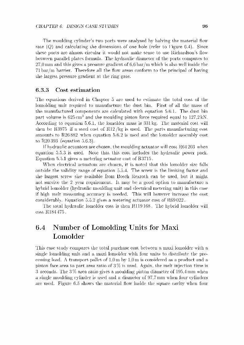
CHAPTER 6. DESIGN CASE STUDIES 96
The moulding cylinder's two ports were analysed by halving the material �owrate (Q) and calculating the dimensions of one hole (refer to Figure 6.4). Sincethese ports are almost circular it would not make sense to use Richardson's �owbetween parallel plates formula. The hydraulic diameter of the ports computes to27,0mm and this gives a pressure gradient of 6,6 bar/m which is also well inside the71 bar/m barrier. Therefore all the �ow areas conform to the principal of havingthe largest pressure gradient at the ring gate.
6.3.3 Cost estimation
The equations derived in Chapter 5 are used to estimate the total cost of thelomolding unit required to manufacture the dust bin. First of all the mass ofthe manufactured components are calculated with equation 5.6.1. The dust binpart volume is 625 cm3 and the moulding piston force required equal to 127,2 kN.According to equation 5.6.1, the lomolder mass is 331 kg. The material cost willthen be R3975 if a steel cost of R12 /kg is used. The parts manufacturing costamounts to R26 882 when equation 5.6.2 is used and the lomolder assembly costto R20 393 (equation 5.6.3).
If hydraulic actuators are chosen, the moulding actuator will cost R64 203 whenequation 5.5.3 is used. Note that this cost includes the hydraulic power pack.Equation 5.5.1 gives a metering actuator cost of R3715 .
When electrical actuators are chosen, it is noted that this lomolder size fallsoutside the validity range of equation 5.5.4. The screw is the limiting factor andthe largest screw size available from Bosch Rexroth can be used, but it mightnot survive the 2 year requirement. It may be a good option to manufacture ahybrid lomolder (hydraulic moulding unit and electrical metering unit) in this caseif high melt measuring accuracy is needed. This will however increase the costconsiderably. Equation 5.5.2 gives a metering actuator cost of R69 022 .
The total hydraulic lomolder cost is then R119 168 . The hybrid lomolder willcost R184 475 .
6.4 Number of Lomolding Units for Maxi
Lomolder
This case study compares the total purchase cost between a maxi lomolder with asingle lomolding unit and a maxi lomolder with four units to distribute the pro-cessing load. A transport pallet of 1,0m by 1,0m is considered as a product and apiston face area to part area ratio of 3% is used. Again, the melt injection time is3 seconds. The 3% area ratio gives a moulding piston diameter of 195,4mm whena single moulding cylinder is used and a diameter of 97,7mm when four cylindersare used. Figure 6.5 shows the material �ow inside the square cavity when four

CHAPTER 6. DESIGN CASE STUDIES 97
cavity@@
@@I
weld line
?
injection ring gate���������
Figure 6.5: Flow front pattern of a lomolder with four lomolding units
moulding cylinders are used. Note the weld lines formation at the position wherethe melt �ow fronts meet.
A cavity injection pressure drop (when four moulding cylinders are used) of115 bar is needed at 75% cavity �ll as calculated by Cadmould. The semi-analyticalresult is inaccurate for this case study, since the Graetz number requirement isnot met. Again, this pressure drop is increased by 25% to account for frictionand miscellaneous e�ects. Therefore, the design pressure drop is 144 bar. Thiscompares to a design pressure drop of 399 bar if a single moulding cylinder is used.Therefore, the piston forces generated are 108 kN for four cylinders and 1197 kNfor one cylinder.
The hydraulic cylinder cost for a single moulding cylinder amounted to R27 060(refer to Table 5.4). Note that this cost was calculated as a combination of thehigh force needed to produce the 3mm thick pallet and the stroke length needed toproduce the 6mm thick pallet. The cost for the four cylinders is calculated next.A hydraulic cylinder with a bore diameter of 80mm is able to deliver a force of125,7 kN at a 250 bar working pressure. The stroke of each of the four cylinders is

CHAPTER 6. DESIGN CASE STUDIES 98
equal to 20 cm to produce a 6mm thick pallet. According to Table A.4 the cost fora single cylinder (front �ange type) is R5455 . Therefore, four cylinders will costR21 820 .
The hydraulic moulding unit cost equation (5.5.3) developed in Chapter 5 can-not be applied directly, as this equation was developed speci�cally for a singlelomolding unit per lomolder. The hydraulic power pack cost is included in thisequation. However, the four moulding cylinders will still be driven by a singlepower pack and the power pack cost does not scale linearly between the number oflomolding units used as shown in the next paragraph.
The hydraulic power pack costs R164 128 to drive a single cylinder. This wascalculated by using equation 5.5.3 and subtracting the cost (R27 060 ) of the singlemoulding cylinder. The power pack cost for the multi moulding piston is calculatedas follows: A hydraulic �uid �ow rate of 42,8 l/min is necessary when the 3,0mmthick part cavity is �lled. The pressure in each of the four cylinders is equal to214,9 bar when a force of 108 kN is delivered. This means that an electric motorof at least 19,1 kW is required if an e�ciency of 80% is used. A 22 kW motor isselected from Table A.1 and costs R9922 . The hydraulic pump with an e�ciencyof 94% must be able to deliver �ow at 59 cc/rev . Therefore, a 71 cc/rev pumpis selected from Table A.2 and costs R59 187 . Adding the pump and motor costamounts to R69 109 for the hydraulic power pack.
It can be argued that the power pack size must be the same, since the samepart is made in the same time under identical processing conditions. However, nolinear relationship exists between the melt pressure drop occurring across the melt�ow path. From the costs calculated above, it can be seen that a four mouldingcylinder con�guration is better sized (for hydraulic power pack optimisation) thana single cylinder con�guration in the case study presented here.
The material, manufacturing and assembly costs are considered next. Four lo-molding units will have a combined mass of 1394 kg, compared to the total mass of3343 kg of one unit. These masses are calculated with equation 5.6.1. Therefore,the material cost di�erence will be R23 388 at R12 /kg. The manufacturing cost(equation 5.6.2) amounts to R107 892 , compared to the R42 541 needed to manu-facture the single lomolding unit con�guration (refer to Table 5.11). The assemblycost (equation 5.6.3) is R82 076 compared to the R41 920 needed to assemble thesingle lomolding unit con�guration. Therefore, the total cost for the multi-pistonlomolder is R297 625 , compared to the R315 765 of the single lomolding unit con-�guration. Table 6.1 summarises the calculated costs.
From these cost �gures, it is cheaper in this case to use four lomolding unitsthan one. Part quality must not be neglected when lomolder costing is considered.A multi-piston environment leads to weld lines forming in moulded parts. If notproperly controlled and positioned, it can decrease the strength of the part consid-erably. This negative aspect must be weighed against the advantage of a smallercavity melt pressure drop that can be obtained with multiple piston con�gurations.

CHAPTER 6. DESIGN CASE STUDIES 99
Table 6.1: Cost comparison between single- and multi-piston lomolder con�gurations
Single piston Multi-pistonMoulding cylinder cost [R] 27 060 21 820
Power pack cost [R] 164 128 69 109Manufactured parts' mass [kg] 3343 1394
Manufactured parts' material cost [R] 40 116 16 728Manufacturing cost [R] 42 541 107 892
Assembly cost [R] 41 920 82 076Total cost [R] 315 765 297 625
It must be noted that no maintenance and operating costs are considered. Itis expected that the maintenance cost will be higher to maintain the multi-pistoncon�guration lomolder. Melt distribution from a plasticiser or compounder to eachlomolding unit is also ignored. This aspect will obviously have cost in�uences.Other con�gurations are also possible, for instance using a single metering cylin-der to measure the melt for all four moulding cylinders. Cost estimation for thiscon�guration can also be done in a similar fashion, but the equations developed inChapter 5 have to be altered. This aspect is not covered in this study.
6.5 Conclusion
This chapter showed the application of the work described in Chapters 2 to 5.Firstly, the semi-analytical model was used to determine the cavity pressure dropto produce a dust bin size part. This pressure drop, together with the requireduser information, were used to size the lomolder with the parametric sizing model.The cost equations of Chapter 5 were used to determine the purchase cost of thelomolding unit components.
The second case study in the chapter showed a cost comparison between asingle- and multi-piston lomolding unit con�guration for a large lomolder. Thepurchase cost of the multi-piston con�guration is slightly less than the single pistoncon�guration. It was argued that this is not the only cost that has to be considered.
The author realises that many di�erent lomolding unit component con�gura-tions and lomolder sizes exist and that two case studies are not enough to testthe cost model thoroughly. However, this work provides a basis to study othercon�gurations and component combinations and illustrates the value of the modelsdeveloped in this dissertation.

Chapter 7
Conclusions
This dissertation discusses the critical design factors that have a large impact onmachine cost for a range of di�erent sized lomolders. Three questions are posed asobjectives to this dissertation:
� What is the optimal ratio of part area to moulding piston face area?
� What type of actuator (hydraulic or electric) must be used?
� What is the optimal number of melt injection moulding cylinders when largerparts are manufactured?
To answer these types of questions, a parametric sizing and cost model wasdeveloped. First of all, a semi-analytical model (Chapter 2) was derived to easethe calculation of part cycle time and cavity pressure drop calculations. The modelproved to be useful for machine costing studies. The model's limitations regardingpart complexity and its dependence on the melt �ow Graetz number were discussed.Estimations can easily be checked with numerical simulation packages, after theinjection time has been estimated using the semi-analytical model.
Various machine layout concepts were discussed in Chapter 3 and the layoutwith the least complexity and disadvantages was chosen for further development.A re�ned design and parametric sizing model, which includes a parametric CADmodel, were developed in Chapter 4. This sizing model is useful in determiningmachine component sizes for various ranges of lomolders. It also provides informa-tion regarding actuator shaft forces, cylinder stroke lengths and actuator speedsrequired.
In Chapter 5 equations were developed to estimate the purchase cost of di�erentsized lomolders. This chapter builds on all the information of Chapters 2 to 4 and isused as input to answer the �rst two questions posted above. Chapter 5 shows thata moulding piston face to e�ective part area ratio of 2,0% to 3,0% is a good choicefor both hydraulic and servo electric con�gurations from a purchase cost point of
100

CHAPTER 7. CONCLUSIONS 101
view. This ratio may be changed if other factors like material shear rate is veryimportant to produce quality parts. Such aspects were, however, not consideredhere.
The parametric and cost models were validated for only three lomolder con�g-urations and more costing research can be done considering more lomolder sizes aswell as di�erent actuator technologies, e.g. cheaper encoders for the servo motorsand �xed hydraulic pump power packs with accumulators. However, a basis is setfor further research regarding these aspects.
The question whether electric or hydraulic actuation is "best" does not have aprecise answer and is very dependent on the purpose of the lomolder. For instance,it was shown that large lomolders (capable of manufacturing large parts) requirevery high moulding actuator forces and that electrical con�gurations are not capableof achieving this. However, on the smaller lomolder cases, the client may requestthat electrical actuators have to be used. Reasons may include accuracy, low noiseand clean environments. It was shown that electrical actuators are more expensive,and therefore hydraulic actuators must be used if cost is the only basis of decision.The main reason is that one power pack can drive both the metering and mouldingactuators, where electrical con�gurations need two servo motors and two drives.
Further, it should be noted, that the costs predicted in Chapter 5 are not in-tended for accurate estimates, but to enable machine designers to evaluate designoptions. These costs were calculated on a quotation basis for the di�erent compo-nents. It is too expensive to validate these quoted costs against costs gathered bybuilding the di�erent sized lomolders.
In Chapter 6, two design case studies show the usefulness of the work presentedin this dissertation. A medium sized lomolder was evaluated and a sizing and cost-ing analysis was performed. It showed the limitations of the electric con�gurationswhen the lomolders become larger. The second case study in Chapter 6 considersthe option of having multiple moulding units injecting melt into the part cavity.It was shown that a multi-piston con�guration was slightly cheaper on a purchasecost point of view than a single piston con�guration for a large part. However,disadvantages are introduced (e.g. weld lines inside the part where the melt �owfronts meet during injection).
The cost model (in particular the equations developed in Chapter 5) can infuture be improved by analysing more lomolder sizes and actual prototype ma-chines' cost. Also, di�erent types of hydraulic and electric con�gurations must beevaluated and compared, since many actuation combinations exist.
Finally, as shown in Chapter 6, this dissertation achieved the objectives set outin Chapter 1, and the parametric sizing and cost model provides a useful tool tooptimise lomolder design con�gurations.

Appendix A
Cost Data
This appendix contains all the hardware cost data that was collected during theresearch done in this dissertation.
Electric motors for
hydraulic power packs4 pole 50 Hz 1450 rpm flange mountedContact: Zest Automation (021) 551-2710
Leon Christians, Jolene HallSize Cost[kW] [R] ex vat3 22084 24555.5 29747.5 367611 567815 730218.5 896622 992230 1194037 1627745 1895255 2337675 2845090 32361110 39177132 47095160 50989
Table A.1: Electric motor cost
102

APPENDIX A. COST DATA 103
Hydraulic pumps for hydraulic power packsContact: Hytec (021-551 4747)Herman van Rensburg
Description Size Cost[#] [cc/rev] [R] ex vat
SYDFE1-2X/018R-PSC12N00-0000-A0X0XX6 18 42222SYDFE1-2X/045R-PPA12N00-0000-A010PXX 45 51789SYDFE1-2X/071R-PPA12N00-0000-A0X0XX5 71 59187A A4VSO 125 HS3P /30R-PPB13N00 125 127225A A4VSO 180 HS3P /30R-PPB13N00 180 140317A A4VSO 250 HS3P /30R-PPB13N00 250 176403
Table A.2: Hydraulic pump cost
Contact: Hytec (021-551 4747)Herman van Rensburg
RETAIL RETAIL RETAIL RETAIL RETAIL
PRICE PRICE PRICE PRICE PRICEBORE 220 280 320 380 420ROD 160 180 220 220 300STROKE 300 200 120 85 60
FRONT FLANGE R 73,820 R 80,240 R 85,240 R 172,545 R 188,980
Table A.3: Hydraulic non-standard cylinder cost

APPENDIX A. COST DATA 104
Contact: Hytec (021-551 4747)
Herman van Rensburg
ISSUE DATE 01/01/2006
VALUED TILL 01/01/2007
RETAIL
RETAIL
RETAIL
RETAIL
RETAIL
RETAIL
RETAIL
RETAIL
RETAIL
DEL: 10-15 WORKING DAYS
PRICE
PRICE
PRICE
PRICE
PRICE
PRICE
PRICE
PRICE
PRICE
BORE
40
50
63
80
100
125
160
200
250
ROD
20
32
40
50
65
80
100
125
160
STROKE
BASIC PRICE
R 2,302
R 2,974
R 3,419
R 4,394
R 4,952
R 7,267
R 9,496
R 13,986
R 12,804
PRICE/100mm
R 70
R 86
R 106
R 146
R 250
R 374
R 570
R 810
R 1,326
PRICE (incl str)
R 2,302
R 2,974
R 3,419
R 4,394
R 4,952
R 7,267
R 9,496
R 13,986
R 12,804
BODY MOUNTING
MALE CLEVIS (MC)
R 3,091
R 3,196
R 3,652
R 4,746
R 5,428
R 8,070
R 10,794
R 15,468
R 23,202
FEMALE CLEVIS (FC)
R 3,130
R 3,227
R 3,686
R 4,785
R 5,515
R 8,186
R 10,925
R 15,851
R 23,777
FRONT FLANGE (FF)
R 3,304
R 3,414
R 3,946
R 5,163
R 5,801
R 8,673
R 11,282
R 16,272
R 24,408
REAR FLANGE (RF)
R 3,304
R 3,401
R 3,932
R 5,076
R 5,714
R 8,575
R 11,086
R 16,174
R 24,260
FOOT MOUNT (FO)
R 3,599
R 3,628
R 4,107
R 5,267
R 5,991
R 9,034
R 11,977
R 17,270
R 25,906
MALE TRUNNION (MT)
R 3,316
R 3,360
R 3,833
R 4,974
R 5,769
R 8,507
R 11,321
R 17,336
R 26,004
SPHERICAL BEARING (SB)
R 2,964
R 3,244
R 3,641
R 4,735
R 5,460
R 8,053
R 11,461
R 18,040
-
ROD END MOUNTING
MALE CLEVIS (MC)
R 213
R 227
R 252
R 375
R 630
R 929
R 1,643
R 2,069
R 1,503
FEMALE CLEVIS (FC)
R 317
R 325
R 419
R 486
R 556
R 1,291
R 2,059
R 2,509
R 1,879
SPHERICAL BEARING (SB)
R 198
R 214
R 349
R 458
R 619
R 1,286
R 2,857
R 6,464
-
H250B SERIES STANDARD CYLINDERS
Table A.4: Hydraulic standard cylinder cost

APPENDIX A. COST DATA 105
Rexroth Precision Screw Assembly
Tectra Automation - 011 971-9400
Kevin Lombard
Part No Length (mm) Description Unit Price
151224013FLANGED SINGLE NUT, FEM-E-S
25 X 10RX3-4 R 2,732.90
151237013FLANGED SINGLE NUT, FEM-E-S
32 X 20RX3,969-2 R 3,333.30
151234013FLANGED SINGLE NUT, FEM-E-S
32 X 10RX3,969-5 R 3,158.30
151234013FLANGED SINGLE NUT, FEM-E-S
32 X 10RX3,969-5 R 3,158.30
151244013FLANGED SINGLE NUT, FEM-E-S
40 X 10RX6-4 R 3,690.10
151244013FLANGED SINGLE NUT, FEM-E-S
40 X 10RX6-4 R 3,690.10
151244013FLANGED SINGLE NUT, FEM-E-S
40 X 10RX6-4 R 3,690.10
151254013FLANGED SINGLE NUT, FEM-E-S
50 X 10RX6-6 R 5,097.20
151264013FLANGED SINGLE NUT, FEM-E-S
63 X 10RX6-6 R 5,940.20
150294002FLANGED SINGLE NUT, FEM-E-S
125 X 10RX6,5-6 R 24,336.50
151124700 704BALL SCREW SPINDLE, CUT TO LENGTH, SIZE 25 X 10R X 3 R 1,766.60
151137710 409BALL SCREW SPINDLE, CUT TO
LENGTH, SIZE 32 X 20R X 3,969 R 1,294.50
151134710 272BALL SCREW SPINDLE, CUT TO
LENGTH, SIZE 32 X 10R X 3,969 R 825.70
151134710 222BALL SCREW SPINDLE, CUT TO
LENGTH, SIZE 32 X 10R X 3,969 R 707.90
151144700 190BALL SCREW SPINDLE, CUT TO LENGTH, SIZE 40 X 10R X 6 R 684.80
151144700 173BALL SCREW SPINDLE, CUT TO LENGTH, SIZE 40 X 10R X 6 R 643.10
151144700 160BALL SCREW SPINDLE, CUT TO LENGTH, SIZE 40 X 10R X 6 R 611.10
151154700 970BALL SCREW SPINDLE, CUT TO LENGTH, SIZE 50 X 10R X 6 R 3,034.20
151164700 590BALL SCREW SPINDLE, CUT TO LENGTH, SIZE 63 X 10R X 6 R 2,429.00
Table A.5: Ballscrew and nut cost

APPENDIX A. COST DATA 106
Rexroth Precision Screw Assembly
Tectra Automation - 011 971-9400
Georg Venter
Mini
Torque reqSelected servo motorCost (ex vat)Selected servo drive
Cost (ex vat)
Area ratio
by servo
[Nm]
[R]
[R]
0.50%
4.17
MSK050C-0600
11301
HCS02.1E-W0028-A-03-NNNN
21898
1.00%
15.60
MSK070D-0300
15030
HCS02.1E-W0054-A-03-NNNN
27342
2.00%
14.84
MSK070D-0300
15030
HCS02.1E-W0054-A-03-NNNN
27342
3.00%
21.26
MSK070E-0300
17712
HCS02.1E-W0054-A-03-NNNN
27342
5.00%
33.15
MSK100C-0300
21969
HCS02.1E-W0054-A-03-NNNN
27342
7.00%
43.09
MSK101D-0200
22725
HCS03.1E-W0070-A-05-NNNV
38334
10.00%
56.38
MSK101E-0200
27289
HCS03.1E-W0070-A-05-NNNV
38334
Midi
Torque reqSelected servo motorCost (ex vat)Selected servo drive
Cost (ex vat)
Area ratio
by servo
[Nm]
[R]
[R]
0.50%
112.77
MAD130C-0250
38696
HCS03.1E-W0100-A-05-NNNV
47877
1.00%
108.83
MAD130C-0250
38696
HCS03.1E-W0100-A-05-NNNV
47877
Table A.6: Servo motor and drive cost

APPENDIX A. COST DATA 107
MINI LOMOLDER METERING UNIT ASSEMBLY
Contact: Grant Hailmer 021 887 9288
COMPONENTS
METERING UNIT ASSEMBLY (MI_LM01_A)
Material cost Manufacturing
Description Drawing No.: Mass (kg) R12/kg Cost
Welding of Metering Support Tube MI_LM0111_A R 525.00
Machining of Lower Flange MI_LM01111_P 0.31 R 3.72 R 222.00
Machining of Motor Support Tube MI_LM01112_P 1.7 R 20.40 R 285.00
Machining of Upper Flange MI_LM01113_P 0.38 R 4.56 R 287.00
Machining of Cylinder MI_LM0112_P 1.27 R 15.24 R 1,250.00
Machining of Bearing Bottom Cover MI_LM0121_P 10.2 R 122.40 R 1,250.00
Machining of Bearing Sleeve Nut MI_LM0122_P 0.041 R 0.49 R 225.00
Machining of Bearing Sleeve Top MI_LM0123_P 1.46 R 17.52 R 605.00
Machining of Piston Skirt MI_LM0131_P 0.22 R 2.64 R 275.00
Machining of Ball Screw Shaft MI_LM0132_P supplied supplied R 250.00
Machining of Piston Clamp MI_LM0133_P 0.3 R 3.60 R 325.00
Machining of Piston Face MI_LM0134_P 0.106 R 1.27 R 125.00
Machining of Motor Plate MI_LM014_P 4.48 R 53.76 R 435.00Machining of Piston Stationary Guide MI_LM015_P 0.6 R 7.20 R 236.00Machining of Sliding Rod MI_LM016_P 2.22 R 26.64 R 620.00Machining of piston Moving Guide MI_LM017_P 2.45 R 29.40 R 399.00
Totals 25.737 R 308.84 R 7,314.00
Table A.7: Mini lomolder metering unit parts cost

APPENDIX A. COST DATA 108
MINI LOMOLDER MOULDING UNIT ASSEMBLY
Contact: Grant Hailmer 021 887 9288
COMPONENTS
MOULDING UNIT ASSEMBLY (MI_LM02_A)
Material cost Manufacturing
Description Drawing No.: Mass (kg) R12/kg Cost
Machining of Transfer Block A MI_LM02111_P 11.9 R 142.80 R 2,400.00
Machining of Transfer Block B MI_LM02112_P 10.9 R 130.80 R 2,400.00
Machining of Transfer Unit Runner MI_LM02113_P 1.89 R 22.68 R 1,050.00
Machining of Transfer Unit End Cap MI_LM02114_P 1.5 R 18.00 R 1,150.00
Machining of Transfer Unit Cylinder MI_LM02115_P 1.143 R 13.72 R 1,250.00
Machininig of Alignment Screw MI_LM0212_P 0.008 R 0.10 R 210.00
Welding of Pipe Support Assembly MI_LM022_A R 525.00
Machining of Pipe Support MI_LM0221_P 2.13 R 25.56 R 725.00
Machining of Pipe Flange MI_LM0222_P 1.01 R 12.12 R 452.00
Machining of Moulding Piston MI_LM0231_P 1.935 R 23.22 R 725.00
Machining of Piston Skirt MI_LM0232_P 0.369 R 4.43 R 375.00
Machining of Moulding Piston Face MI_LM0233_P 0.076 R 0.91 R 825.00
Machining of Moulding Piston Guide MI_LM0234_P 0.98 R 11.76 R 1,550.00
Machining of Piston Ball Screw MI_LM0235_P supplied supplied R 250.00
Machining of Bearing Bottom Cover MI_LM0241_P 5.69 R 68.28 R 475.00
Machining of Bearing Sleeve Nut MI_LM0242_P 0.083 R 1.00 R 275.00
Machining of Bearing Sleeve Top MI_LM0243_P 1.471 R 17.65 R 650.00Machining of Moulding Motor Plate MI_LM025_P 7.7 R 92.40 R 580.00Machining of Platen Stud MI_LM03_P 1.08 R 12.96 R 900.00Machining of Sliding Rod MI_LM04_P 3.59 R 43.08 R 1,700.00
Totals 53.46 R 641.46 R 18,467.00
Table A.8: Mini lomolder moulding unit parts cost

APPENDIX A. COST DATA 109
MAXI LOMOLDER METERING UNIT ASSEMBLY
Contact: Grant Hailmer 021 887 9288
COMPONENTS
METERING UNIT ASSEMBLY (MA_LM01_A)
Manufacturing Material cost
Description Drawing No.: Mass (kg) Cost R12/kg
Welding of Metering Support Tube MI_LM0111_A R 525.00
Machining of Lower Flange MA_LM01111_P 4.89 R 58.68 R 391.00
Machining of Motor Support Tube MA_LM01112_P 27.62 R 331.44 R 1,650.00
Machining of Upper Flange MA_LM01113_P 8.15 R 97.80 R 476.00
Machining of Cylinder MA_LM0112_P 10.4 R 124.80 R 1,165.00
Machining of Bearing Bottom Cover MA_LM0121_P 53.27 R 639.24 R 1,450.00
Machining of Bearing Sleeve Nut MA_LM0122_P 0.179 R 2.15 R 325.00
Machining of Bearing Sleeve Top MA_LM0123_P 13.98 R 167.76 R 725.00
Machining of Piston Skirt MA_LM0131_P 4.59 R 55.08 R 385.00
Machining of Ball Screw Shaft MA_LM0132_P supplied supplied R 250.00
Machining of Piston Clamp MA_LM0133_P 6.16 R 73.92 R 425.00
Machining of Piston Face MA_LM0134_P 1.48 R 17.76 R 250.00
Machining of Motor Plate MA_LM014_P 101.03 R 1,212.36 R 1,698.00Machining of Piston Stationary Guide MA_LM015_P 10.93 R 131.16 R 688.00Machining of Sliding Rod MA_LM016_P 20.714 R 248.57 R 1,250.00Machining of piston Moving Guide MA_LM017_P 66.32 R 795.84 R 1,848.00
Totals 329.71 R 3,956.56 R 13,501.00
Table A.9: Maxi lomolder metering unit parts cost
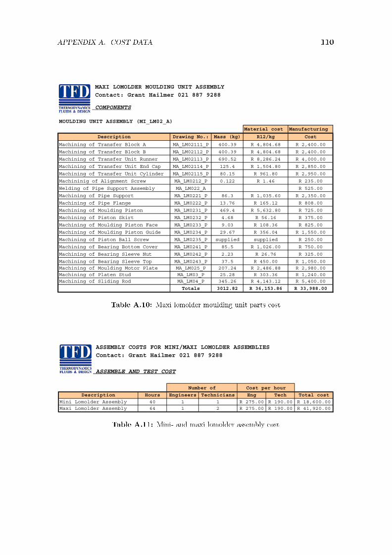
APPENDIX A. COST DATA 110
MAXI LOMOLDER MOULDING UNIT ASSEMBLY
Contact: Grant Hailmer 021 887 9288
COMPONENTS
MOULDING UNIT ASSEMBLY (MI_LM02_A)
Material cost Manufacturing
Description Drawing No.: Mass (kg) R12/kg Cost
Machining of Transfer Block A MA_LM02111_P 400.39 R 4,804.68 R 2,400.00
Machining of Transfer Block B MA_LM02112_P 400.39 R 4,804.68 R 2,400.00
Machining of Transfer Unit Runner MA_LM02113_P 690.52 R 8,286.24 R 4,000.00
Machining of Transfer Unit End Cap MA_LM02114_P 125.4 R 1,504.80 R 2,850.00
Machining of Transfer Unit Cylinder MA_LM02115_P 80.15 R 961.80 R 2,950.00
Machininig of Alignment Screw MA_LM0212_P 0.122 R 1.46 R 235.00
Welding of Pipe Support Assembly MA_LM022_A R 525.00
Machining of Pipe Support MA_LM0221_P 86.3 R 1,035.60 R 2,350.00
Machining of Pipe Flange MA_LM0222_P 13.76 R 165.12 R 808.00
Machining of Moulding Piston MA_LM0231_P 469.4 R 5,632.80 R 725.00
Machining of Piston Skirt MA_LM0232_P 4.68 R 56.16 R 375.00
Machining of Moulding Piston Face MA_LM0233_P 9.03 R 108.36 R 825.00
Machining of Moulding Piston Guide MA_LM0234_P 29.67 R 356.04 R 1,550.00
Machining of Piston Ball Screw MA_LM0235_P supplied supplied R 250.00
Machining of Bearing Bottom Cover MA_LM0241_P 85.5 R 1,026.00 R 750.00
Machining of Bearing Sleeve Nut MA_LM0242_P 2.23 R 26.76 R 325.00
Machining of Bearing Sleeve Top MA_LM0243_P 37.5 R 450.00 R 1,050.00Machining of Moulding Motor Plate MA_LM025_P 207.24 R 2,486.88 R 2,980.00Machining of Platen Stud MA_LM03_P 25.28 R 303.36 R 1,240.00Machining of Sliding Rod MA_LM04_P 345.26 R 4,143.12 R 5,400.00
Totals 3012.82 R 36,153.86 R 33,988.00
Table A.10: Maxi lomolder moulding unit parts cost
ASSEMBLY COSTS FOR MINI/MAXI LOMOLDER ASSEMBLIES
Contact: Grant Hailmer 021 887 9288
ASSEMBLE AND TEST COST
Description Hours Engineers Technicians Eng Tech Total cost
Mini Lomolder Assembly 40 1 1 R 275.00 R 190.00 R 18,600.00Maxi Lomolder Assembly 64 1 2 R 275.00 R 190.00 R 41,920.00
Number of Cost per hour
Table A.11: Mini- and maxi lomolder assembly cost
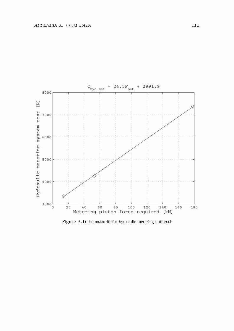
APPENDIX A. COST DATA 111
0 20 40 60 80 100 120 140 160 1803000
4000
5000
6000
7000
8000
Chyd met
= 24.5Fmet
+ 2991.9
Metering piston force required [kN]
Hydraulic metering system cost [R]
Figure A.1: Equation �t for hydraulic metering unit cost

APPENDIX A. COST DATA 112
0 200 400 600 800 1000 120040
60
80
100
120
140
160
180
200
Chyd mol
= 118.7Fmol
+ 49104
Moulding piston force required [kN]
Hydraulic moulding system cost [1000R]
Figure A.2: Equation �t for hydraulic moulding unit cost

APPENDIX A. COST DATA 113
0 500 1000 1500 2000 2500 3000 35000
500
1000
1500
2000
2500
3000
3500Lomolder scaling parameter (eq. 5.6.1)
Lomolder unit mass [kg]Lomolder mass as calculated by eq. 5.6.1 [kg]
Figure A.3: Equation �t for lomolding unit mass

List of References
Benham, P.P., Crawford, R.J. and Armstrong, C.G. (1996). Mechanics of Engineering
Materials. 2nd edn. Addison Wesley Longman Limited, England.
Bernhardt, E.C. (1983). Computer Aided Engineering for Injection Moulding. HanserPublishers.
Blanchard, B.S. and Fabrycky, W.J. (1997). Systems Engineering and Analysis. 3rd edn.Prentice Hall International, Upper Saddle River, New Jersey 07458.
Bracke, P. (2006). Personal Communication: CEO of Engel, South Africa.
Cadmould (2002). v6. Simcon Kunststo�technische Software GmbH, Germany.Available at: www.simcon-worldwide.com
Chen, Y-M. and Liu, J-J. (1999). Cost-e�ective design for injection moulding. Roboticsand Computer-Integrated Manufacturing, vol. 15, pp. 1�21.
Dietz, W., White, J.L. and Clark, E.S. (1978). Orientation development and relaxation ininjection moulding of amorphous polymers. Polymer Engineering and Science, vol. 18,no. 4, pp. 273�281.
Dymond, J.A.D. (2004). The simulation of the �ow of polymer melt in lomolding. Master'sthesis, Stellenbosch University.
Eckardt, H. and Stemke, L. (2000). Verfahren und vorrichtung zum spritzgiessen vonkunststo�-formteilen. European Patent O�ce. EP1090734A1.
Gao, D.M., Nguyen, K.T., Girard, P. and Salloum, G. (1994). E�ect of variable injec-tion speed in injection mould �lling. In: Proceedings of the 52nd Annual Technical
Conference. Published by the Society of Plastic Engineers, Brook�eld, CT, USA, pp.712-715.
Goussard, C.L. and Basson, A.H. (2006a). Cavity pressure estimation for a piston mould-ing life cycle cost model. In: Proceedings of the TMCE 2006, pp. 767�774. Ljubljana,Slovenia.
Goussard, C.L. and Basson, A.H. (2006b). Parametric design model for the optimisationof a piston moulding machine. In: The 16th CIRP International Design Seminar, pp.786�792. Alberta, Canada.
114

LIST OF REFERENCES 115
Goussard, C.L. and Basson, A.H. (2006c). Cavity pressure estimation for a piston mould-ing life cycle cost model. Journal of Mechanical Engineering, Slovenia. Accepted.
Goussard, C.L. and Basson, A.H. (2007). Concept evaluation and layout design of a pistonmoulding machine. In: International Conference on Engineering Design 2007. Paris,France. Accepted.
Hill, D. (1996). Further studies of the injection moulding process. Applied Math Modelling,vol. 20, pp. 719�730.
Hsing-Lung, L. and Hwang, G.J. (1977). An experiment on liquid solidi�cation in thermalentrance region of a circular tube. Letters in Heat Mass Transfer, vol. 4, pp. 437�444.
Janeschitz-Kriegl, H. (1977). Injection moulding of plastics: Some ideas about the rela-tionship between mould �lling and birefringence. Rheol. Acta, vol. 16, pp. 327�339.
Janeschitz-Kriegl, H. (1979). Injection moulding of plastics: II. Analytical solution ofheat transfer problem. Rheol. Acta, vol. 18, pp. 693�701.
Johnson, B.A. (2006). The in�uence of processing on properties of injection-moulded and
lomolded components. Master's thesis, Stellenbosch University.
Jones, R.F. (1998). Guide to Short Fiber Reinforced Plastics. Society of Plastic Engineers,Hanser Publishers, Munich.
Joubert, F. (2005). Rapid tooling and the lomold process. Master's thesis, StellenboschUniversity.
Kim, S-W. and Turng, L-S. (2004). Developments of three-dimensional computer-aidedengineering simulation for injection moulding. Modelling and Simulation in Materials
Science and Engineering, vol. 12, pp. 151�173.
Lee, D.G. and Zerkle, R.D. (1969). The e�ect of liquid solidi�cation in a parallel-platechannel upon laminar �ow heat transfer and pressure drop. ASME Journal of Heat
Transfer, vol. 91, pp. 583�585.
Lee, R-S., Chen, Y-M. and Lee, C-Z. (1997). Development of a concurrent mold designsystem: A knowledge-based approach. Computer Integrated Manufacturing Systems,vol. 10, no. 4, pp. 287�307.
Manzione, L.T. (1987). Applications of Computer Aided Engineering in Injection Mould-
ing. Hanser Publishers, New York.
Matsuoka, T., Takabatake, J-I., Koiwai, A., Inoue, Y., Yamamoto, S. and Takahashi, H.(1991). Integrated simulation to predict warpage of injection moulded parts. PolymerEngineering and Science, vol. 31, no. 14, pp. 1043�1050.

LIST OF REFERENCES 116
Mavridis, H., Hrymak, A.N. and Vlachopoulos, J. (1986). Mathematical modeling ofinjection mold �lling: A review. Advances in Polymer Technology, vol. 6, no. 4, pp.457�466.
Osswald, T.A. and Menges, G. (1995). Materials Science of Polymers for Engineers.Hanser Publishers, Munich, Vienna, New York.
Rexroth Bosch Group (2002). Rexroth Precision Ball Screw Assemblies, End Bearings
and Nut Housings, RE 83 301/2002-09 edn.
Richardson, S.M. (1983). Injection moulding of thermoplastics: Freezing during mould�lling. Rheol. Acta, vol. 22, pp. 223�236.
Richardson, S.M. (1985a). Injection moulding of thermoplastics. I. Freezing-o� at gates.Rheol. Acta, vol. 24, pp. 497�508.
Richardson, S.M. (1985b). Injection moulding of thermoplastics. II. Freezing-o� in cavi-ties. Rheol. Acta, vol. 24, pp. 509�518.
Richardson, S.M. (1986a). Injection moulding of thermoplastics: Freezing of variable-viscosity �uids. Developing �ows with very high heat generation. Rheol. Acta, vol. 25,pp. 180�190.
Richardson, S.M. (1986b). Injection moulding of thermoplastics: Freezing of variable-viscosity �uids. Developing �ows with very low heat generation. Rheol. Acta, vol. 25,pp. 308�318.
Richardson, S.M. (1986c). Injection moulding of thermoplastics: Freezing of variable-viscosity �uids. Fully-developed �ows. Rheol. Acta, vol. 25, pp. 372�379.
Richardson, S.M. (1987). Freezing-o� in disc cavities. Rheol. Acta, vol. 26, pp. 102�105.
Richardson, S.M., Pearson, H.J. and Pearson, J.R.A. (1980). Simulation of injectionmoulding. Plastic and Rubber: Processing, vol. 5, pp. 55�60.
Schacht, T., Maier, U., Esser, K., Kretzschmar, O. and Schmidt, T. (1985). CAE/CADin injection moulding, blow moulding, and foam moulding - the shortest way to moulddesign. Advances in Polymer Technology, vol. 5, no. 2, pp. 99�137.
Singh, K.J. and Wang, H.P. (1982). Computer analysis to optimise mould cooling process.Society of Plastics Engineers: Technical Papers, vol. 28, pp. 330�331.
Spiracon (2007). Spiracon roller screws. Power Jacks Ltd., South Harbour Road, Fraser-burgh AB43 9BZ Scotland. (23 March 2007).Available at: http://www.powerjacks.com
Venter, G. (2007). Personal Communication: Sales Division of Tectra Automation SouthAfrica.

LIST OF REFERENCES 117
Viehweg, W. (2006). Personal Communication: Maintenance Engineer at Circuit BreakerIndustries, South Africa.
Wang, V.W., Hieber, C.A. and Wang, K.K. (1986). Filling of an arbitrary three-dimensional thin cavity. Journal of Polymer Engineering, vol. 7, no. 1, pp. 21�45.
Weigand, B. and Beer, H. (1991). Heat transfer and solidi�cation of a laminar liquid �owin a cooled parallel plate channel: The stationary case. Wärme- und Sto�übertragung,vol. 19, pp. 233�240.
Weir, C.J. (1975). Introduction to Injection Moulding. Society of Plastic Engineers, 656West Putnam Avenue, Greenwich, Conn. 06830.
Yang, L.C., Chen, S.J. and Charmchi, M. (1991). Steady solidi�cation of non-Newtonian�uid �owing in a round tube. Polymer Engineering and Science, vol. 31, no. 3, pp.191�196.
Zerkle, R.D. and Sunderland, J.E. (1968). The e�ect of liquid solidi�cation in a tubeupon laminar �ow heat transfer and pressure drop. ASME Journal of Heat Transfer,vol. 90, pp. 183�190.
Zhang, G. and Thompson, M.R. (2005). Reduced �bre breakage in a glass-�bre reinforcedthermoplastic through foaming. Composites Science and Technology, vol. 65, pp. 2240�2249.