Embed Size (px)
Citation preview

Project Code: RLN-0503
Design, Modeling, and Analysis of an Inline Assembly Machine
A Major Qualifying Project Report Submitted to the Faculty of
WORCESTER POLYTECHNIC INSTITUTE &
GILLETTE In partial fulfillment of the requirements for the
Degree of Bachelor of Science
By:
_____________________________ Casey Kenniston
_____________________________ Vicente F. Nogarotto
_____________________________ Michael Seabrook
Date: 20 April, 2006
Advisor: Robert L. Norton

ii

iii
Abstract This project takes a fresh look at the design of an indexing machine with regard to arrangement and placement of camshafts, ground supports, link geometry, and follower
train configurations to determine if a different arrangement would be superior. The new design is based on results acquired from vibration and deflection analysis of the current
assembly machine configuration. The design approach provides commonality between parts, reduces vibrations, and increases productivity. The final design is a nine-station,
inline assembly machine with two camshafts. Every station is able to actuate two horizontal motions and one vertical motion at the indexing nest.

iv
Acknowledgements The accomplishments of this project would never have been possible without the guidance of the following people. We would like to thank our liaison at Gillette, Tim
Sweet, for conceiving this project and providing us with the information required to conduct a thorough report, including CAD drawings, CAD models, and machine
specifications. Thanks also to the Gillette engineers who gave us feedback on our report, and helped guide us in the right direction. We would also like to thank Gillette for
sponsoring our major qualifying project (MQP) as well as its continued support of WPI’s projects.
We would like to especially thank our advisor, Professor Robert L. Norton, who made
this project possible. He was involved in guiding us through every aspect of this project from concept generation through to the detailed analysis and the report format.
We sincerely thank each of you for your hard work, dedication, and support throughout
this undertaking.

v
Table of Contents
1.0 Introduction................................................................................................................... 1 2.0 Approach....................................................................................................................... 2 3.0 Goal Statement.............................................................................................................. 2
3.1 Functional Requirements .......................................................................................... 2 4.0 Background Information............................................................................................... 3
4.1 Machine Summaries.................................................................................................. 3 4.1.1 Blade Assembly Machine .................................................................................. 3 4.1.2 Venus Cartridge Machine .................................................................................. 6 4.1.3 Venus Razor Machine........................................................................................ 6 4.1.4 Current Configuration Images ........................................................................... 6
4.2 Patent Research......................................................................................................... 8 4.3 Motors ....................................................................................................................... 8 4.4 Mechanisms for Power Transfer............................................................................... 8 4.5 Work-Space Ergonomics .......................................................................................... 9
5.0 Initial Design Concepts............................................................................................... 10 5.1 Design 1: Dual Overhead Camshaft v1.0 ............................................................... 11 5.2 Design 2: Single Overhead Camshaft ..................................................................... 12 5.3 Design 3: Dual Overhead Camshaft v2.0 ............................................................... 14 5.4 Design 4: Rear Dual Overhead Camshafts ............................................................. 15 5.5 Design 5: Transverse Camshaft .............................................................................. 16 5.6 Decision Matrix for Designs 1-5............................................................................. 17 5.7 Refined Initial Design Concepts ............................................................................. 19
5.7.1 Design 2: Single Overhead Camshaft .............................................................. 19 5.7.2 Design 3: Dual Overhead Camshaft ................................................................ 20 5.7.3 Design 5: Transverse Camshaft ....................................................................... 21
5.8 Bringing Old and New Ideas Together ................................................................... 22 6.0 Analysis....................................................................................................................... 23
6.1 Camshaft Size and Distance between Supports ...................................................... 23 6.1.1 Camshaft Analysis Set-up................................................................................ 24 6.1.2 Camshaft Analysis Results .............................................................................. 28 6.1.3 Camshaft Analysis Conclusions ...................................................................... 34
6.2 Determining the Final Design’s Tooling Tolerance ............................................... 34 6.3 Ground-Bar Analysis Set-up................................................................................... 34
6.4 Vibration Analysis of linkage train..................................................................... 38 6.4.1 Modeling technique for Analysis..................................................................... 39 6.4.2 Existing Linkage train information.................................................................. 42 6.4.3 Sensitivity Experiment..................................................................................... 45 6.4.4 Statistical Methods used .................................................................................. 50 6.4.5 Results of Sensitivity Experiment.................................................................... 51
7.0 Final Design Description ............................................................................................ 53 7.1 Upper Linkage Systems .......................................................................................... 56 7.2 Lower Linkage Systems.......................................................................................... 58 7.3 Link Redesign ......................................................................................................... 61
7.3.1 Cam Follower Levers....................................................................................... 61

vi
7.3.2 Bell Crank Design for Upper Linkages ........................................................... 64 7.3.3 Bell crank for Lower Linkages ........................................................................ 65
7.4 Motor and Belt Configuration................................................................................. 66 8.0 Vibration Analysis of New Design ............................................................................. 67 9.0 Conclusions and Recommendations ........................................................................... 74 10.0 Summary of Findings................................................................................................ 78
Vibration Analysis .................................................................................................... 78 Deflection Analysis................................................................................................... 78 Final Design Features ............................................................................................... 79
11.0 References................................................................................................................. 81 Appendix A: Background Research.................................................................................. 83 Appendix B: MathCAD & Dynacam Model for Camshaft Analysis ............................. 108 Appendix C: MathCAD model used for Vibration Simulation ...................................... 117 Appendix D: Summary of Camshaft Iterations .............................................................. 123 Appendix E: MathCAD Model of Ground Deflections.................................................. 125 Appendix F: Determining Ground Support Forces......................................................... 132 Appendix G: Determining the Torsional Deflection of the Ground Bar ........................ 134 Appendix H: Initial Design Concepts ............................................................................. 137 Appendix I: Deflection Distribution Graphs................................................................... 155 Appendix J: Graphs of Vibration Noise for Sensitivity Experiment .............................. 159 Appendix K: Additional Illustrations of Final Design.................................................... 163

vii
List of Figures Figure 1: Single Station of an Assembly Machine ............................................................. 5 Figure 2: Typical Configuration for an Assembly Station.................................................. 7 Figure 3: Design 1: Dual Overhead Camshaft v1.0.......................................................... 11 Figure 4: Design 2: Single Overhead Camshaft ............................................................... 12 Figure 5: Design 3............................................................................................................. 14 Figure 6: Design 4............................................................................................................. 15 Figure 7: Transverse Camshaft ......................................................................................... 16 Figure 8: Design 2: Single Overhead Camshaft ............................................................... 19 Figure 9: Design 3: Dual Overhead Camshaft .................................................................. 20 Figure 10: Design 5: Transverse Camshaft....................................................................... 21 Figure 11: Transverse Camshaft 1:1 Configuration.......................................................... 21 Figure 12: Final Design Concept Sketch .......................................................................... 22 Figure 13: Camshaft with six supports ............................................................................. 24 Figure 14: Description of fixed-fixed end condition ........................................................ 25 Figure 15: Design 1: Three Supports Evenly Spaced ....................................................... 26 Figure 16: Design 2: Four Supports Evenly Spaced......................................................... 26 Figure 17: Design 3: Six Supports (Original Set-up)........................................................ 26 Figure 18: Design 4: Six Supports Evenly Spaced ........................................................... 26 Figure 19: Design 5: Seven Supports Evenly Spaced....................................................... 27 Figure 20: Design 4 Details .............................................................................................. 27 Figure 21: FBD of a shaft segment in Design 4................................................................ 27 Figure 22: Design 4: Effect of Diameter on Deflection................................................... 29 Figure 23: Effect of Diameter on Torsional Deflection.................................................... 29 Figure 24: Diameter vs. Maximum Deflection ................................................................. 31 Figure 25: Distance between Supports (Design #) vs. Bending Deflection ..................... 32 Figure 26: Diameter vs. Maximum Torsional Deflection................................................. 33 Figure 27: Distance between Supports (Designs) vs. Maximum Torsional Deflection ... 33 Figure 28: FBD of Upper Ground..................................................................................... 35 Figure 29: Forces on the Cam follower due to the Cam................................................... 36 Figure 30: Direction of Deflections .................................................................................. 36 Figure 31: Lumped Mass model of linkage train.............................................................. 39 Figure 32: Lumped mass at the Cam ................................................................................ 40 Figure 33: S, V, A functions for CAM ............................................................................. 41 Figure 34: Boundary Conditions for FEA of 36040er ...................................................... 42 Figure 35: Displacement Distribution of 36040er ............................................................ 43 Figure 36: 36040abl .......................................................................................................... 44 Figure 37: Finding Stiffness 4........................................................................................... 44 Figure 38: Finding Stiffness 5........................................................................................... 45 Figure 39: Cam Follower lever Modified ......................................................................... 46 Figure 40: RMS Comparison Graph ................................................................................. 51 Figure 41: Percent Change Graph..................................................................................... 52 Figure 42: Final Design’s Isometric View........................................................................ 53 Figure 43: Front and Side View of Assembly Machine ................................................... 54 Figure 44: a: Upper Linkage, b: Lower Linkage Right, c: Lower Linkage Left .............. 55

viii
Figure 45: Upper Linkage System .................................................................................... 56 Figure 46: Upper Ground bar Configuration .................................................................... 57 Figure 47: Lower Linkage Configuration "A".................................................................. 58 Figure 48: Lower Linkage Configuration "B" .................................................................. 59 Figure 49: Lower Ground bar Configuration.................................................................... 60 Figure 50: Cam Follower for Vertical and Right Horizontal Linkages Front View......... 62 Figure 51: Cam Follower for Vertical and Horizontal Motion Linkages Top View........ 62 Figure 52: Cam Follower Assembly................................................................................. 63 Figure 53: Right Horizontal Motion Bell Crank part A.................................................... 64 Figure 54: Right Horizontal Motion Bell Crank part B.................................................... 64 Figure 55: Bell Crank........................................................................................................ 65 Figure 56: Motor and Belt Configuration ......................................................................... 66 Figure 57: Graph of RMS values for Varying Shaft speeds ............................................. 72 Figure 58: FFT Magnitude of cam at 180 RPM ............................................................... 73 Figure 59: Final Design .................................................................................................... 80 Figure 60: Commonly actuated in-line assembly Machine .............................................. 84 Figure 61: Side View of Commonly Actuated inline assembly machine......................... 84 Figure 62: Form closed cam configuration....................................................................... 85 Figure 63: Multiple Spindle Rotary Indexing Machine Tool ........................................... 86 Figure 64: Top view of Multiple Spindle Rotary Indexing Machine ............................... 87 Figure 65: Modular Assembly Machine ........................................................................... 88 Figure 66: Assembly Machine .......................................................................................... 89 Figure 67: Drawing of an Alpha Gear TP+ inline planetary gear box ............................. 92 Figure 68: Hypoid Gear 90 degree Gear Box ................................................................... 92 Figure 69: Alpha Gear SK+ 90 degree Gear Box (mm) ................................................... 93 Figure 70: Typical and Double Enveloping Worm Gears ................................................ 93 Figure 71: Akron Double Enveloping Worm Gear Size Chart......................................... 94 Figure 72: Roller Chain .................................................................................................... 97 Figure 73: Double Pitch .................................................................................................... 98 Figure 74: Inverted Silent Tooth....................................................................................... 98 Figure 75: Offset Sidebar.................................................................................................. 99 Figure 76: Detachable Chains........................................................................................... 99 Figure 77: Flat Belt ......................................................................................................... 101 Figure 78: Classical V-Belt............................................................................................. 102 Figure 79: Narrow V-Belt............................................................................................... 102 Figure 80: V-Ribbed Belt................................................................................................ 103 Figure 81: Joined V-Belt................................................................................................. 103 Figure 82: Synchronous Belt .......................................................................................... 105 Figure 83: Selected Anthropometric Measurements....................................................... 106 Figure 84: Selected Anthropometric Measurements....................................................... 106 Figure 85: Standing Workspace Measurements ............................................................. 107 Figure 86: Sitting Workspace Measurements ................................................................. 107 Figure 87: Force and Torque Graphs .............................................................................. 108 Figure 88: Close up of Cam Follower............................................................................. 132 Figure 89: FBD of Cam Follower................................................................................... 132 Figure 90: FBD of the Cam follower.............................................................................. 134

ix
Figure 91: Forces on the Cam follower due to the Cam................................................. 135 Figure 92: Conservative Cross Section of Clamp........................................................... 136 Figure 93: Isometric View of Design 2........................................................................... 139 Figure 94: Side View of Design 2................................................................................... 140 Figure 95: Perspective View of Design 2 Support Structure.......................................... 141 Figure 96: Perspective Views of Design 2...................................................................... 142 Figure 97: Design 2 - Individual Camshafts and Motors................................................ 143 Figure 98: Design 2 - Coupled Shaft with one Motor .................................................... 143 Figure 99: Isometric View of Design 3........................................................................... 144 Figure 100: Front View of Design 3 ............................................................................... 145 Figure 101: Front view of Support Structure.................................................................. 146 Figure 102: Side View of Support Structure................................................................... 147 Figure 103: Side view of Fully Modular Approach........................................................ 148 Figure 104: Two Full Line Shafts................................................................................... 149 Figure 105: Single Line Shaft with Sub-shafts ............................................................... 150 Figure 106: Transverse Design ....................................................................................... 151 Figure 107: Front View Transverse System ................................................................... 152 Figure 108: Operator Side View Transverse System...................................................... 153 Figure 109: Complete Modular Assembly...................................................................... 154 Figure 110: Redesigned Cam Follower for Vertical and Right horizontal Linkages ..... 155 Figure 111: Redesigned Cam follower for left horizontal motion linkages ................... 155 Figure 112: Finding K5 for redesigned Left Horizontal Motion Bell Crank.................. 156 Figure 113: K4 for Redesigned Left Horizontal Motion Bell Crank.............................. 157 Figure 114: K4 for Redesigned Right Horizontal Motion Bell Crank............................ 158 Figure 115: K5 for Redesigned Right Horizontal Motion Bell Crank............................ 158 Figure 116: Unwanted vibrations of system with Original Links................................... 159 Figure 117: Unwanted vibrations of System with Connection Rod half ........................ 159 Figure 118: Unwanted vibrations of system with Connecting Rod doubled .................. 160 Figure 119: Unwanted vibrations of system with Cam Follower +5 mm ...................... 160 Figure 120: Unwanted vibrations of system with Cam Follower +10 mm .................... 161 Figure 121: Unwanted vibrations of system with rocker lever +5 mm .......................... 161 Figure 122: Unwanted vibrations of system with rocker lever +10 mm ........................ 162 Figure 123: Unwanted vibrations of system with all links improved............................. 162 Figure 124: Right Side View .......................................................................................... 163 Figure 125: Front Side View........................................................................................... 164 Figure 126: Left Side View............................................................................................. 165 Figure 127: Back Side View........................................................................................... 166 Figure 128: Top Perspective View ................................................................................. 167 Figure 129: Front Close-up Perspective ......................................................................... 168 Figure 130: Front Perspective......................................................................................... 169 Figure 131: Back Perspective ......................................................................................... 170

x
List of Tables Table 1: Decision Matrix .................................................................................................. 18 Table 2: Summary of Iterations ........................................................................................ 25 Table 3: Summary of Design 4 ......................................................................................... 28 Table 4: Summary of Maximum Deflections for Designs 1 – 5....................................... 30 Table 5: Summary of Maximum Torsional Deflections ................................................... 34 Table 6: Summary of Deflections ..................................................................................... 37 Table 7: Summary of Tolerances...................................................................................... 37 Table 8: Summary of Iteration Input Data........................................................................ 49 Table 9: Final Linkage Data ............................................................................................. 68 Table 10: RMS Values...................................................................................................... 69 Table 11: Effective Stiffness............................................................................................. 70 Table 12: RMS values for Varying Camshaft Speeds ...................................................... 71 Table 13: Natural Frequencies .......................................................................................... 74 Table 14: Summary of Deflections ................................................................................... 76 Table 15: Summary of Tolerances.................................................................................... 76 Table 16: Summary of Camshaft Configurations ........................................................... 138
List of Equations Equation 1: Vibration Differential Equation (10.9b)........................................................ 41 Equation 2: Stiffness of beam in compression.................................................................. 43 Equation 3: Change in Mass ............................................................................................. 47 Equation 4: Area Moment of inertia ................................................................................. 47 Equation 5: Original Area Moment of Inertia................................................................... 47 Equation 6: Resulting Area Moment of Inertia................................................................. 47 Equation 7: Change in Area Moment of Inertia................................................................ 47 Equation 8: Stiffness of Beam in Bending........................................................................ 47 Equation 9: Resulting Stiffness......................................................................................... 48 Equation 10: Noise function ............................................................................................. 50 Equation 11: RMS equation.............................................................................................. 50 Equation 12: RMS Percent Change .................................................................................. 50 Equation 13: Maximum Deflection for a Cantilever Beam........................................... 135

xi
Executive Summary Gillette is considering new designs for inline indexing assembly machines. The inline machines used by Gillette have reached the current design’s full potential in terms of
productive operational speed. The purpose of this project is to examine and model the current machines in order to identify weak areas and to use this information to develop a
new design for the inline indexing assembly machine.
The current chassis design consists of an indexing conveyor, where the product is located and worked on, and two camshafts. One camshaft is located directly below the indexing
conveyor while the second camshaft is located under and towards the backside of the machine. Long, cam-driven linkage trains are driven from the camshafts and make their
way to where the product is located on the indexing conveyor.
Gillette wants to run these inline indexing assembly machines above 300 parts per minute (PPM). In order to increase the current operating speed of 200 PPM to 300 PPM it is
necessary to redesign the current machine chassis so that overall vibrations are kept to a minimum at higher speed. If the current machines were to be run at 300 PPM the
vibration levels would cause unacceptable end effector errors.
The new design was developed through modeling and analysis in the following areas:
• Camshaft Design and Support Arrangement
• Ground support Design
• Vibration Analysis
The camshaft design and support arrangement analysis seeks to answer questions such as what the camshaft diameter should be, and to identify the optimal support arrangement to
minimize shaft deflections. The new ground supports provide stiffer ground pivots for the linkage trains. The new link pivot ground bars are designed to have minimal
deflections. Finally, vibration analysis is used to accomplish two tasks. The first task is

xii
to understand the sensitivity of the linkage train to vibrations when changes are made to particular links. The results of the sensitivity experiment were used to improve the
design of the current links. The second task is the vibration analysis accomplishes is to analyze the simulated vibration noise of the new design and compare the results to the
simulated vibrations of a current linkage train used by Gillette.
The processes and results obtained are described in this report. The report includes a description of the final design and its components as well as the methods used to develop
the analyses for examining the current machine and the new design. Also included is a record of results of the analyses completed along with recommendations for future
studies that could be done to bring this design to the next stage.

1
1.0 Introduction Many of the Gillette Company’s production machines use a conveyor to move products from one tooling station to the next. The products are rapidly indexed from station to
station and then held stationary while the assembly or manufacturing operation is performed on the product. These machines are required to be extremely accurate and
reliable due to the value of time and material.
The current configuration of a typical production machine uses cam-driven linkages to provide both the indexing motion of the belt and the assembly motions at each of the
stations. The chassis of the current machines have two camshafts that run the length of the machines and are driven synchronously with the conveyor as shown in Figure 1.
These camshafts are located deep within the chassis of the machine, resulting in long and heavy linkage trains. These linkage trains can cause dynamic problems such as
vibrations that limit the speed and accuracy at which products can be assembled. Also, because the camshafts are buried deep within the chassis of the machine, access to the
camshafts is difficult, resulting in an increase of maintenance downtime.
This project takes a “clean sheet of paper” look at the design of an indexing machine with regard to arrangement and placement of camshafts, cams, ground points, link geometry,
and follower train configurations to determine if a different arrangement would be superior. The new design is based on the results acquired from modeling, and vibration
and deflection analysis of the current assembly machine. The design approach provides commonality between parts, reduces vibrations, and can increase productivity. The final
design is a nine station inline assembly machine with two camshafts and with every station being able to actuate two horizontal motions and one vertical motion.
The design takes into consideration human factors such as ease of access to the product
for the operators and ease of access to the mechanisms that may need replacement by the mechanics. By addressing these issues, downtime can be reduced in the event of jams and
part replacements.

2
2.0 Approach The approach taken was to analyze and understand the function and dynamic limitations of the current assembly machines by modeling their behavior. Based on this
understanding, alternative design configurations were developed. The most promising of these concepts was then designed and analyzed using the models previously developed.
This report will present our understandings of the present machine design and operation
followed by their analysis with various dynamic and structural models. Finally, an improved design will be presented
3.0 Goal Statement The goal of this project is to generate a new design for an inline assembly machine. The new design will be based upon the results from analysis of the current assembly machine.
The design approach will provide commonality between parts, reduce mass of moving parts, increase the stiffness and reduce vibrations. The generic tooling station will have
two horizontal motions and one vertical motion.
3.1 Functional Requirements
• Reduce mass of moving elements
• Increase stiffness of moving elements
• Reduce vibration levels
• Increase commonality between tooling parts and assemblies
• Minimize adjustability of components
• Provide desirable tooling motions
• Accurately position a floating nest
• Must not take up more floor space than the current machines
• Means to synchronize tooling motions with indexing motion
• Must be easily maintained by mechanic
• Must be easily accessed by operator
• Increase reliability

3
o Reduce downtime o Run smoother
o Reduce scrap rate
• Must accommodate current feeding stations
• Tooling accuracy of +/- 0.1mm
• Maximum camshaft torsional deflection of +/- 2.5 degrees
4.0 Background Information This section presents an overview of the research conducted for this project. The different machines at Gillette are described to clarify the issues being faced in each
indexing machine and a research into specific mechanisms that may need incorporation in concept generation is conducted. Servo motors, patents, and different power transfer
mechanism are researched and discussed along with research of work-space ergonomics that may affect the designs. More detailed information about each topic can be found in
Appendix A.
4.1 Machine Summaries Three Gillette assembly machines were studied to understand their indexing machines. These machines include the Blade Assembly Machine, Venus Cartridge Machine, and
Venus Razor Machine. The advantages and disadvantages of each machine were noted along with the advancements made with the newer machines.
4.1.1 Blade Assembly Machine
The Blade Assembly Machine (BAM) design is approximately 25 years old and was
originally designed to run at 110 PPM. Its design has been modified and improved, and as a result is currently running at 225 PPM. In this machine, a blade is joined to an
angled support by laser welding; the blade is then sheared off to proper width. This process is completed with multiple cam and linkage systems arranged along an indexing
conveyor.

4
There are two cam shafts turning cams that move the linkage systems on this machine. The main shaft is driven by a motor which is connected to a gearbox and then to a cam
box. The slave shaft is run by a timing belt from the main shaft. The two shafts drive linkages that provide the proper vertical and horizontal motions needed to assemble the
blade. The cams on the shafts are split into two halves to allow replacement without having to take the entire cam shaft off the machine. The cam providing the welding arm
motion is reduced by a 2:1 ratio compared to the motion of the other cams, so that there is less wasted motion. An air cylinder is used to keep the roller followers on the cams,
because any skip of the follower from the cam would cause a crash and damage the tooling. A non-servo motor machine does not allow the machine to stop as rapidly as
does a servo motor driven machine. The connecting rods of the linkages in this machine are made from solid aluminum and their length can be adjusted during machine setup.
The connecting rods are fairly long and there are vibration issues. The fixed pivots of the linkage systems overhang the rectangular ground bar, acting as a cantilever beam, and
can be seen in Figure 1. This is an area of concern as it creates a significant moment about the ground bar, causing the ground bar to move. There is uniformity among the
levers and connecting rods, which allows for easy maintenance. There are standard tooling bridges and the indexing table, which is supported by a 1.5 inch thick steel slab to
reduce vibrations, is about normal table height. Figure 1 shows a labeled station of an assembly machine.

5
Main Cam Shaft
Slave Cam Shaft Air Cylinder
Rocker Arm
Con-rod
Indexing Conveyor Tooling Bridge
Groundbars
Cantilevered Ground Pivot (1)
Cam Lever
Figure 1: Single Station of an Assembly Machine

6
4.1.2 Venus Cartridge Machine
The Venus Cartridge Assembly Machine is a later generation assembly machine. It performs similar tasks as the BAM but improvements have been made to the overall
design. Speed has not been increased and it runs at 185 PPM. The machine is designed for 250 PPM, but this production rate is not needed for this product. The chassis to this
machine is similar to the BAM, but is more robust. There are two servomotor-driven camshafts with a larger diameter than the cam shafts on the BAM. The servomotors
allow the machine to stop almost instantly in case of a crash. Accelerometers have been mounted on the machine to detect crashes and automatically stop the machine. The
connecting rods in the linkage systems are made of hollow steel tubes and cannot be length-adjusted as in the BAM. The fixed pivots of the cam levers overhang the ground
bar and are of concern due to the applied moment. This machine has greater uniformity between its parts and linkages than the BAM.
4.1.3 Venus Razor Machine
The Venus Razor Handle Machine is an extremely large and bulky machine. It currently runs at 77 PPM. The large mass of the parts in the system cause large dynamic forces;
vibrations have been measured in excess of 40 G’s on some follower trains. As a result, there are high inertia forces, high impact loads, and significant vibration on the linkages. Also, the use of chains on some cam drives allows for backlash and unwanted movement.
4.1.4 Current Configuration Images
A typical configuration for one of the cam linkage system on an assembly machine is illustrated in Figure 2. The linkage configurations vary from one station to the next;
however, camshafts are continuous along the entire machine.

7
Slave Cam Shaft
Con-rod
Cantilevered Ground Pivot
Air Cylinders
Main Cam Shaft
Indexing Conveyor
Groundbars
Cam Follower Lever
Figure 2: Typical Configuration for an Assembly Station

8
4.2 Patent Research Existing designs of indexing machine chassis and tooling linkage configurations were researched for background information. There were four relevant patents found and they
include a Commonly Actuated in-line Assembly Machine, a Multiple Spindle Rotary Indexing Machine Tool, a Modular Assembly machine, and an Assembly Machine. The
research illustrated different types of indexing machines and helped generate ideas for the new machine design. Detailed descriptions for each of the aforementioned machines can
be seen in Appendix A.
4.3 Motors The method of powering the camshaft is crucial to how well the machine can run. The motor selected must produce enough power to the camshaft and keep sufficient timing
accuracy between the conveyor and itself. DC and AC servo motors were explored due to their ability to quickly start and stop and maintain accurate speeds against varying
loads. Based on the research, either an AC or DC servo motor would be appropriate. The detailed research can be found in Appendix A.
4.4 Mechanisms for Power Transfer Because a possible solution to our project may include multiple camshafts, different ways to transfer power from one camshaft to the other were researched. Three common
methods of power transfer are gears, chain drives, and flexible belts. Because of synchronization requirements between the camshafts, synchronous belts and inverted
tooth chains are the two most viable options. Other chain types were eliminated due to their backlash and gears due to the long distance between camshafts. More in-depth
research can be found in Appendix A.

9
4.5 Work-Space Ergonomics Work-space ergonomics are very important in the design of a new machine. Operators
and mechanics must be access to the different parts of the machine, while avoiding strenuous positions. There is a visual and manual area for the average person who is
sitting or standing. The average size of males and females was researched along with work-space measurements. Creating a comfortable working environment is important to
the health of the individual working on the machine. The complete study can be found in Appendix A.

10
5.0 Initial Design Concepts It is important to note that this project evolved significantly as time progressed. Because the initial problem statement was somewhat broad, the initial design approach pursued a
unique “modular” design. In a modular design each station is an assembly in itself, having a core framework with similar parts and features, but still able to perform
different tooling motions. These “modules” could be removed from the machines and replaced by other similar modules depending on the application without significantly
affecting the other modules.
After discussing this idea with Gillette engineers, the design approach was changed; a more conventional design approach was taken due to feasibility and practicality. The
initial designs for this project were still viable design ideas. However, for the design to work, the modular stations described in this section were viewed as ideas to be
incorporated on an entire machine.
Several concepts were generated and then graded in order to eliminate concepts that did not meet the functional requirements. This left five viable designs for evaluation.
Three designs emerged from the decision matrix and were further developed for presentation to Gillette engineers. The following sections describe the five original
designs and the decision matrix used to further narrow them down. Notice that all designs attempts to bring the camshaft close to the tooling stations in order to reduce the
size of the linkage trains and to improve access.

11
5.1 Design 1: Dual Overhead Camshaft v1.0
Figure 3: Design 1: Dual Overhead Camshaft v1.0 Figure 3 shows design 1, the dual overhead camshaft. The design uses two camshafts
that are located above the tooling stations. Currently the camshafts run underneath the indexing conveyor, this results in relatively long linkages. For this reason, having a
design that brings camshafts above the indexing conveyor would reduce the length of the linkage systems, therefore reducing the vibration levels.
The vertical motion includes a follower arm labeled B in Figure 3; the follower arm
drives a connecting rod labeled C. The horizontal motions are driven by a cam follower which directly attaches to the tooling. There is no need for a connecting rod for the
horizontal motions due to the configuration of the cam follower lever. The resulting design is a symmetric linkage configuration. The cam follower levers use a 1:1 lever

12
ratio therefore not increasing the effective mass of the system at the cam. One of the camshafts would need to support more than one cam depending on what tooling motions
were needed at the given station. The identical linkage configurations for the horizontal motions would help in decreasing the need to have different parts produced for
replacements.
5.2 Design 2: Single Overhead Camshaft
Figure 4: Design 2: Single Overhead Camshaft

13
Design 2, shown in Figure 4, uses a single camshaft, labeled A. The camshaft will support all three of the cams that will drive the vertical motion and two horizontal
motions for the tooling. The vertical motion is produced using a cam follower lever labeled C in Figure 4. The cam follower lever will be positioned on the bottom of the
cam. Attempts will be made to use 1:1 lever ratios so there is no increase of effective mass felt at the cam. The left horizontal motion includes a long cam follower lever that
will connect to a connecting rod labeled D. The connecting rod will then transfer the vertical motion to a horizontal motion using a bell crank labeled E. The cam follower
lever for the left horizontal motion will also be positioned on the bottom of the cam and will use a 1:1 lever ratio. The left horizontal motion tooling linkage will not be in the
same plane as the nest where the work will be done; therefore it will be necessary to use a small shaft to offset the motion produced by the tooling linkage into the appropriate plane.
This small shaft most likely will be placed at the ground point of the bell crank offsetting the motion the needed distance.
The right side horizontal motion has a slightly different configuration. It uses a cam
follower lever labeled B in Figure 4. This cam follower lever has a 2:1 lever ratio which will result in an increase of effective mass felt at the cam. Though there will be an increase in effective mass, the overall mass of the linkage has been reduced and possibly
redesigning the cam follower lever and connecting rods will result in an even further reduction in mass. The cam follower is then connected to a connecting rod which
transfers the vertical motion to a horizontal motion using the bell crank.
Using a single camshaft saves room that would be taken up by a second camshaft, resulting in greater access to the nest for the operator. Another advantage is that most
maintenance could be performed from one side of the machine. This would reduce the down time for repairs and reconfigurations.

14
5.3 Design 3: Dual Overhead Camshaft v2.0
Figure 5: Design 3 Design 3, Figure 5 is a variation of design 1. The design has two camshafts running
above the tooling station with the cam driven tooling linkages coming off of them. The vertical motion uses a cam follower labeled A3 connected to a small connecting rod
labeled B3. The horizontal motions are identical on either side of the machine. Instead of using a rather long cam follower lever with no connecting rod to achieve the desired
motion this design uses cam follower levers, labeled A1 and A2, which are positioned on the top of the cams. The cam follower then connects to the connecting rod, B1 or B2,
which then converts the vertical motion to the horizontal motion using the bell crank, C1 or C2. The design is symmetric allowing for accessibility for the mechanics as well as the machine operator. Design 3 also allows for a more compact design because of the

15
linkage configuration, the camshafts can be positioned closer to the center of the machine. The two horizontal motions linkages have a 2:1 lever ratio for the cam follower lever,
while the vertical motion linkage has a 1:1 lever ratio. Though the horizontal motions have a less favorable lever ratio, the increase in effective mass would be less than the
current effective masses experienced because the current linkages are longer than those in design 3.
5.4 Design 4: Rear Dual Overhead Camshafts
Figure 6: Design 4
Design 4, shown in Figure 6, again has two camshafts that are located above the tooling stations like Designs 1 and 3. The major difference is that the camshafts are not
positioned symmetrically about the tooling station; they are off to one side. The vertical motion is accomplished through camshaft 1, cam follower A2 and connecting rod B2.
Cam follower lever A2 has a 1:1 lever ratio. The horizontal motions are achieved through links A1, B1, C1 and links A3, B3, C3. Cam follower levers A1 and A3 have a
1:1 lever ratio. Bell cranks C1 and C3 convert the vertical motion provided by the cam

16
follower and connecting rod into the desired horizontal motion. Systems A1, B1, C1 and A2, B2 are running off of camshaft 1, while system A3, B3, C3 is running off of
camshaft 2. This design allows for easier access to the tooling from one side. It also has the potential of being easily maintenance because the mechanic will only need to access
one side of the machine.
5.5 Design 5: Transverse Camshaft Design 5 is a different concept than all previous designs. This camshaft runs perpendicular to the index motion of the machine. The overall linkage system is very
similar to design 3. Cam follower levers A1, A2, and A3 are identical and provide a 2:1 lever ratio in the configuration below. This design is not limited to a 2:1 ratio as it could
easily be changed to a 1:1 ratio. Both options will be explored for their advantages and disadvantages. The commonality of the cam follower levers allows for a common ground point between all the linkages. All air cylinders would also be on a common ground
point, allowing for the roller to be pulled off the cam to provide for a lockout. The system A2, B2 provides the vertical motion desired. The horizontal motion is provided
by systems A1, B1, C1 and A3, B3, C3. The horizontal motion linkage systems are identical. Bell cranks C1 and C3 convert the vertical motion of the cam follower levers
into the desired horizontal motion. Figure 7 shows what the potential system would look like.
Figure 7: Transverse Camshaft

17
5.6 Decision Matrix for Designs 1-5 In order to choose the best of the five modular designs, a decision matrix was created to grade the five concepts. The designs were graded on an absolute scale from negative five
to positive five in eight different functional requirements. This matrix can be seen in Table 1.
The functional requirements chosen for grading the concepts are:
• Maintenance, grades the design on how easily a mechanic can access parts and
fix the machine.
• Modularity, encompasses the design’s ability to have common parts, common ground pivots, and common location of components.
• Compactness, represents location of components with respect to one another.
• Mass of moving parts, represents the mass properties of the elements.
• Accessibility for the operator, which means that if a jam occurs at the nest, how
accessible is the area for the operator.
• Link Ratios, grades the concepts with one to one ratios the best and so on down
the line.
• Length of links, grades the designs on overall link lengths
• Number of Camshafts, represents how many parts will be needed and other
requirements of having more shafts.

18
Table 1: Decision Matrix
Design 1 Design 2 Design 3 Design 4 Design 5 Weighing
Factor Maintenance 1 3 2 -2 0 0.15 Modularity 3.25 2.5 3.25 2.5 4 0.125
Compactness -1 2.5 1 1.5 3.5 0.125 Mass of Moving
Parts -1 2 1.5 1.5 3 0.2 Length of links 0 2 2.5 2 3.5 0.05
Operator Accessability 1 2.5 1 1.5 1.5 0.15 Link Ratios 5 3 3 5 3 0.1 Number of Camshafts 2 3 2 2 3 0.1
Total 1.08 2.55 1.91 1.53 2.54 1
Based on this grading scheme, design 2 shows the most promise. The design avoids
many of the problems with transferring power to multiple camshafts (belts, chains, gears, etc.). Looking more at the ergonomics of the machine; locating one camshaft towards the top back of the machine, the operator can work standing up and does not have to go to the
front of the machine.
Design 5 also had a relatively high grade. Similar to design 2, the transverse camshaft avoids many of power transfer problems. This configuration allows for good ground
point locations, which is important to maintain an uncongested work area. A drawback of this design is difficult access to the middle cam.
Design 3 was also taken to the next design phase due to its flexibility for configurations
and short link combinations. Solid models were created and more refinement were introduced into the concepts until more accurate distinctions between each concept could
be made.

19
5.7 Refined Initial Design Concepts The following sections explore the revisions and development of the top three designs;
Design 2: Single Overhead Camshaft, Design 3: Dual Overhead Camshaft, and Design 5: Transverse Camshaft. More information pertaining to these designs can be found in
Appendix H.
5.7.1 Design 2: Single Overhead Camshaft The single overhead design shown in Figure 8 has three motions, two horizontal and one
vertical; all cams are located on a single camshaft. The vertical and back horizontal motions have 2:1 lever ratios, and the front horizontal motion has a 1:1 ratio. Links 1, 2,
and 3 are all about 280 mm long. Connecting rods 4 and 5 are about 290 mm long and rod 6 is about 220 mm long. This design is fairly open because it only requires two
ground bars, but because there’s only one camshaft, it is limited to 3 or 4 cams per station.
The overhead cam is located slightly towards the back of the machine so the supporting structure can be designed to attach only to the back base plate leaving the front of the
machine open.
a) With support structure shown b) Support structure removed for clarity
Figure 8: Design 2: Single Overhead Camshaft

20
5.7.2 Design 3: Dual Overhead Camshaft The dual overhead design shown in Figure 9 has three motions. One camshaft
accommodates the cams for the vertical and the back horizontal motions, while the other camshaft has the cam for the front horizontal motion. All the linkages have a 2-1 lever
ratio. Links 1, 2, and 3 are about 250 mm long. Connecting rods 4 and 6 are about 310 mm long, and rod 5 is about 165 mm long. This design requires the supporting structure to wrap around the conveyor belt and results in difficult operator access. It also requires
four ground bars to accommodate the air cylinders and cam followers. However, with two camshafts, there is enough room for more camshafts than the single overhead design.
Figure 9: Design 3: Dual Overhead Camshaft

21
5.7.3 Design 5: Transverse Camshaft The transverse design only applies to a modular approach because the camshaft runs
perpendicular to the indexing motion of the machine. The single camshaft accommodates all the cams required for a station. This unique approach allows
flexibility to have either all 2:1 or all 1:1 lever ratios. Figure 10 shows a 2:1 configuration and Figure 11 shows a 1:1 arrangement. For the 1:1 configuration, the link lengths are as follows. Cam followers 1, 2, and 3 are about 300 mm long. Connecting
rods 4 and 5 are about 290 mm long and connecting rod 6 is about 150 mm long.
Figure 10: Design 5: Transverse Camshaft
Figure 11: Transverse Camshaft 1:1 Configuration

22
5.8 Bringing Old and New Ideas Together Upon further evaluation and discussion with Gillette engineers, the design that was most
appropriate for the project’s new direction was the single overhead camshaft design. The transverse design was eliminated due to its inherent modular approach and the dual
overhead design was eliminated due to its accessibility issues. However, the single overhead design has one major flaw; it has a limit on how many cams can be placed per
station. The final design took this into account.
A compromise between optimal camshaft locations, functionality, and access issues was made for the final design. The attempt was to reduce vibrations and link lengths while
maintaining clear access. The new design shown in Figure 12 uses the single overhead camshaft concept. To address possible operations below the conveyor belt and limited
camshaft space, a second camshaft was located under the conveyor belt. The lower camshaft was lined up horizontally with the center of the conveyor belt for symmetry, but
its vertical location was optimized. As mentioned earlier, these are not the optimal locations for the camshafts, but based on our research, they are the best compromise.
Original Single Overhead Design
Figure 12: Final Design Concept Sketch

23
6.0 Analysis The final design concept started with the analysis of the current cam and linkage system on the blade assembly machine. This was vital to evaluate the performance of the current
machine and what changes would make a difference in the overall effectiveness of the machine. This analysis provided a good understanding to guide the design process.
In conjunction with the modeling of the final design, analysis of some identified
important components were performed to increase the effectiveness of the machine. An increase in productivity can only be achieved by designing a system that can run faster
and maintain or improve the accuracy of the current machine. To become faster and more accurate, the system must become stiffer, therefore reducing deflections.
One of the goals of the analysis was to determine the optimal combination between
camshaft support distances and camshaft diameter. The effect of changing the cross section of the current ground bars was also looked at to help stiffen the ground points and
improve accuracy.
A vibration analysis of the linkage systems was also performed. The goal of this analysis was to understand what the critical elements in the linkage train contribute the most to the
vibrations and how these elements can be designed to improve the overall linkage train. The final design was based on the result of both the deflection and vibration analysis.
6.1 Camshaft Size and Distance between Supports The analysis described in this section was conducted to determine a good combination between the distance between the camshaft supports and the camshaft diameter. There
were two variables of concern in the analysis; camshaft bending and torsional deflections. The number of supports determined by the camshaft analysis was also used as the number
of supports between the ground bars (for simplicity and due to space and access issues). An appropriate cross section for the ground bar was found so that when the maximum
deflections of the camshaft and the ground bars were combined, an accuracy of +/-0.1mm was achieved. Also, the camshaft had to be within +/- 2.5 degrees in torsional deflection.

24
This section will describe how the camshaft model was set-up, including the assumptions
that were made. It will then describe the process taken to analyze the camshaft leading to our final design decisions.
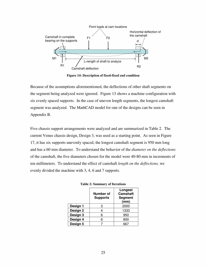
6.1.1 Camshaft Analysis Set-up Using MathCAD, sections of the camshaft, seen circled in Figure 13, were analyzed for different camshaft lengths. Refer to Figure 14 for the following explanation of the free body diagram. The camshaft was assumed to have bearing along the entire width d of the
support and the bending deflection of the camshaft to be small compared to the size of the camshaft. With small bending deflections, the horizontal deflection of the camshaft was
ignored and fixed-fixed end conditions for the camshaft were justified. This allowed analysis to be conducted on length L.
Because the widths of the cams are small compared to the length of the camshaft, point
loads were chosen to represent the loads exerted by the cams on the camshaft and are shown as F1 and F2.
Figure 13: Camshaft with six supports
25
Camshaft in complete bearing on the supports
L=length of shaft to analyze
F1 F2
Point loads at cam locations
Camshaft deflection
Horizontal deflection of the camshaft
d
R1 R2
M2M1
Figure 14: Description of fixed-fixed end condition
Because of the assumptions aforementioned, the deflections of other shaft segments on the segment being analyzed were ignored. Figure 13 shows a machine configuration with
six evenly spaced supports. In the case of uneven length segments, the longest camshaft segment was analyzed. The MathCAD model for one of the designs can be seen in
Appendix B.
Five chassis support arrangements were analyzed and are summarized in Table 2. The current Venus chassis design, Design 3, was used as a starting point. As seen in Figure
17, it has six supports unevenly spaced; the longest camshaft segment is 950 mm long and has a 60 mm diameter. To understand the behavior of the diameter on the deflections
of the camshaft, the five diameters chosen for the model were 40-80 mm in increments of ten millimeters. To understand the effect of camshaft length on the deflections, we
evenly divided the machine with 3, 4, 6 and 7 supports.
Table 2: Summary of Iterations
Number of Supports
Longest Camshaft Segment
(mm) Design 1 3 2000 Design 2 4 1333 Design 3 6 950 Design 4 6 800 Design 5 7 667

26
Figure 15 through Figure 19 are representations of iterations conducted. The longer lines extending upward represent the supports and the shorter lines extending downward
represent cams. Cams spaced close together represent a tooling station and there are ten stations in every arrangement. Dimensions between stations are all between 10-15 inches
as is common in the current machines and are divided as evenly as possible to accommodate all ten stations.
Figure 15: Design 1: Three Supports Evenly Spaced
Figure 16: Design 2: Four Supports Evenly Spaced
worse case segment for this design
Figure 17: Design 3: Six Supports (Original Set-up)
Segment Analyzed
Figure 18: Design 4: Six Supports Evenly Spaced

27
Figure 19: Design 5: Seven Supports Evenly Spaced
The following description is of design 4, seen in Figure 20, but applies to all of the
iterations conducted. The current machine has a distance between tooling stations (x1) ranging from 10 to 15 inches (254 to 380mm) and is able to accommodate about 10
stations along its length. The current back camshaft has two cams per station, one for the vertical and one for the back horizontal motion, at a distance x2 of about 3.22in (82mm)
apart. Calculations of forces and torques associated with the camshaft analysis can be seen in Appendix B and are F = 886 N and T = 17 N*m. Figure 21 shows the free body
diagram (FBD) for the shaft segment in design 4.
x1
x2
x3
104 5 6 7 8 931 2
Figure 20: Design 4 Details
Fixed FixedF2F1 F3 F4
a c db
R1 R2
M2M1
Figure 21: FBD of a shaft segment in Design 4
Iterations were then conducted varying the support distances (x3 in Figure 20) and the camshaft diameters to determine how both bending and torsional defections behave. This
set of data was three dimensional because bending deflection was analyzed with respect to the camshaft length and against varying diameters. Torsional deflection had a three
dimensional set of data for the same reasons.

28
6.1.2 Camshaft Analysis Results With the model set-up, deflections for Design 1 through 5 were calculated and the effects of diameter on deflections for each configuration were compared. The calculations
showed all designs behave in the same way; the maximum bending deflection y occurred towards the middle and no deflection at the support ends as illustrated in Figure 22.
Torsional deflection decreased as the diameter was increased as shown in Figure 23. Both graphs shown are for design 4 and the summary is listed in Table 3. Appendix D includes a summary of all the cases.
Table 3 shows that both bending and torsional deflections reduce by about one half every
time the diameter is increased by 10 mm, exhibiting an exponential behavior.
Table 3: Summary of Design 4 Total Length 4000 mm # Supports 6 Distance btw supports 800 mm Distance btw stations 300 mm Distance btw cams (in station) 82.5 mm # Stations 2 # of cams 4 Diameter 40 50 60 70 80 mm Max Deflection (y) 0.193 0.079 0.038 0.026 0.012 mm Max Deflection (torsion) 1.919 0.786 0.379 0.205 0.120 deg

29
Effect of Diameter on Design 4
-2.5E-04
-2.0E-04
-1.5E-04
-1.0E-04
-5.0E-05
0.0E+000 100 200 300 400 500 600 700 800
Distance x (mm)
Defle
ctio
n (y
) m
40mm50mm60mm70mm80mm
Figure 22: Design 4: Effect of Diameter on Deflection
Effect of Diameter on Torsional Deflection in Design 4
0.0
0.5
1.0
1.5
2.0
2.5
30 40 50 60 70 80 90Diameters (mm)
Tors
iona
l Def
lect
ion
(deg
)
Figure 23: Effect of Diameter on Torsional Deflection

30
Comparing the Effects of Diameter and Support Distances on Deflection To observe the effect of the maximum camshaft deflections on tooling end accuracy, a comparison of the maximum deflections from each of the five designs was conducted.
As mentioned earlier, the deflections must be compared against camshaft diameters and support distances to determine their behavior.
Bending Deflection Comparisons
Table 4 lists the maximum bending deflection of all designs corresponding to the
respective diameters and Figure 24 illustrates their exponential behavior; as diameters increase, bending deflections (y) decrease. When comparing designs, designs 1 and 2
show large improvements in deflection as the shaft segment is shortened, but in designs 3-5 (950 mm, 800 mm, and 667 mm, respectively), the improvement in deflection
becomes very small. This shows that increasing the number of supports to more then six on a 4000 mm machine does not result in a significant improvement in stiffness.
Table 4: Summary of Maximum Deflections for Designs 1 – 5
Diameters 40 50 60 70 80 mm Design 1 7.550 3.050 1.470 0.795 7.550 mm Design 2 1.630 0.669 0.323 0.174 1.630 mm Design 3 0.420 0.172 0.083 0.045 0.420 mm Design 4 0.193 0.079 0.038 0.026 0.193 mm Design 5 0.101 0.041 0.019 0.011 0.101 mm

31
Max Deflection Comparsion (Diameter vs. Bending Deflection)
0
1
2
3
4
5
6
7
8
30 40 50 60 70 80 90Diameter (mm)
Defle
ctio
n (y
) m
m Design 1Design 2Design 3Design 4Design 5
Figure 24: Diameter vs. Maximum Deflection
Next, the effect of the support distances (Design #’s) on the maximum bending deflection was observed, refer to Figure 25. As the distance between supports decreases, bending
deflections decreases. Designs 1 and 2 show large improvements in deflection as the diameter increases, but because of the exponential behavior, only small improvements in
deflections are gained in designs 3-5. This shows that with six or more supports (shaft segment less then or equal to 800 mm long), a camshaft diameter larger than 60 mm is not justifiable.

32
Max Deflection Comparison (Design # vs Bending Deflection)
0
1
2
3
4
5
6
7
8
0 1 2 3 4 5 6Design #
Defle
ctio
n (y
) m
m 4050607080
Figure 25: Distance between Supports (Design #) vs. Bending Deflection
Torsional Deflection Comparisons Torsional deflection versus both support distances and camshaft diameters were also observed. Figure 26 illustrates that torsional deflection decreases for all designs as the
diameter increases. What is not quite clear is why the torsional deflections for all designs decrease by about the same amount. This is due to the location of the cams along the
camshaft. Only small changes in cam locations are made between designs and can be seen in Figure 15 through Figure 19. When Figure 27 is graphed, it becomes more
apparent that torsional deflection is nearly constant as the distance between the supports change.
A summary of the torsional defections for the five designs can be seen in Table 5.

33
Torsional Deflection Comparision (Diameter vs. Torsional Deflection)
0
0.5
1
1.5
2
2.5
30 40 50 60 70 80 90Diameter (mm)
Tors
ion
(deg
) Design 1Design 2Design 3Design 4Design 5
Figure 26: Diameter vs. Maximum Torsional Deflection
Torsional Deflection Comparison ( Design # vs Torsional Deflection)
0
0.5
1
1.5
2
2.5
0 1 2 3 4 5 6
Design #
Tors
iona
l Def
lect
ion
(deg
)
4050607080
Figure 27: Distance between Supports (Designs) vs. Maximum Torsional Deflection

34
Table 5: Summary of Maximum Torsional Deflections
Diameter 40 50 60 70 80 mm Design 1 1.920 0.786 0.379 0.205 0.119 deg Design 2 1.760 0.721 0.348 0.188 0.110 deg Design 3 1.820 0.748 0.361 0.195 0.114 deg Design 4 1.919 0.786 0.379 0.205 0.120 deg Design 5 1.650 0.675 0.326 0.176 0.103 deg
6.1.3 Camshaft Analysis Conclusions We concluded that spacing between camshaft supports is a parameter independent of the
machine length and dependent on camshaft diameter. For a 4000 mm long machine, reasonable deflections were achieved with a combination of six supports evenly spaced
(800 mm between supports) and a 60 mm shaft diameter. Figure 25 shows that with fewer than six supports, the knee in the exponential curve is approached, drastically increasing
camshaft deflection. More than six supports does not improve the system enough to warrant another support and reduces operator and mechanic access. The current 60 mm diameter camshaft can be used in this set-up because deflection improvements with larger
diameters are not significant.
6.2 Determining the Final Design’s Tooling Tolerance The ground supports currently in use were also evaluated and optimized because the deflections of the ground supports contribute to inaccuracies at the tooling end effector.
In order to use the conclusions made from the camshaft analysis (six supports and a 60 mm shaft diameter), the ground supports were designed so when both camshaft and
ground support deflections were combined, the end-effector error was within +/- 0.1 mm.
6.3 Ground-Bar Analysis Set-up MathCAD was also used to model the ground supports. With the assumption of two
cams per station, the ground bars on the top and the bottom of the machine each have two links grounded to them. Analysis was only conducted on the upper ground supports due

35
to the similarity between the upper and lower supports. The upper supports have two linkage systems, one performing a vertical motion and the other a horizontal motion.
Accuracies for both these linkages were compared to the allowable tolerance.
The same assumptions made in the camshaft analysis were made for the ground bar analysis. The ground bar segments were modeled with fixed-fixed end conditions with
concentrated loads at the ground link locations. The FBD of a ground-bar segment can be seen in Figure 28. See Appendix E for the MathCAD model.
Fixed FixedF2F1
a b
R1 R2
M2
M1
Figure 28: FBD of Upper Ground
The calculation of forces F1 and F2 can be seen in Appendix B. They are equal to each
other and push the ground supports up. Their values are F1 = F2 = 687 N.
As illustrate in Figure 29, the ground bar is also subjected to torsion. With the cam rotating in a clockwise direction, the maximum normal force occurs at the maximum pressure angle, producing a component in the x and y directions. The component causing
torsion on the ground bar is force Fx as illustrated in Figure 29. The deflections due to torsion were so small; they were left out of the analysis. The deflection in the x direction
is equal to 0.000150 mm and the deflection in the y direction is virtually zero. Calculations for these deflections can be seen in Appendix G.

36
dd Fx
Fy Fn
Fx
Figure 29: Forces on the Cam follower due to the Cam
A comparison between the old ground bars and a stiffer cross section was made to determine how much improvement could be gained. The model was first run with the
current 50x30 mm cross section and then modified to 50x50 mm. The deflection of the ground bars and the camshaft were combined, as shown in Figure 30, and then compared.
The assumption was that the maximum camshaft deflection acted down at the same time the maximum ground deflection acted up, resulting in the largest possible deflection.
Figure 30: Direction of Deflections

37
Using lever ratios, the deflection from the camshaft and the ground supports were traced down to the tooling end. Table 6 shows a summary of the deflections for the ground bar.
Table 7 shows a summary of the tolerances resulted from these deflections.
Table 6: Summary of Deflections
Ground Deflection Comparison New Bar 50x50 mm 0.016 mm Original Bar 30x50 mm 0.072 mm Camshaft Deflection 0.038 mm
Table 7: Summary of Tolerances
Summary of Tolerance +/- mm Top Horizontal Top Vertical New Bar 50x50 mm +/- 0.12 +/- 0.0915 mm Original Bar 30x50 mm +/- 0.20 mm +/- 0.148 mm
A significant improvement in the tolerance was accomplished by using a square 50x50 mm cross section. Due to the conservative approach taken and time constraints, this was
a significant improvement in the tolerance and was used in the final design.

38
6.4 Vibration Analysis of linkage train High levels of vibrations are a major reason why the current machines cannot run faster.
Running the current machine at a higher speed would result in vibration levels that could cause unacceptable end effector error. In order to design a new machine to run with
lower vibrations it is necessary to understand what causes the vibrations.
The scope of the vibration analysis is limited to the vibrations of the linkage trains. The key reasons for limiting the analysis to linkage trains were time limitations and because it
was determined that understanding the linkage trains would provide the most direction for an initial redesign of the machine. Future vibration analysis of support structures and
other components could be done in order to further improve the overall vibration levels of the machine.
The analysis consists of five major areas:
• Model Design
• Initial data collection
• Sensitivity experiment
• Data interpretation
• Results
39
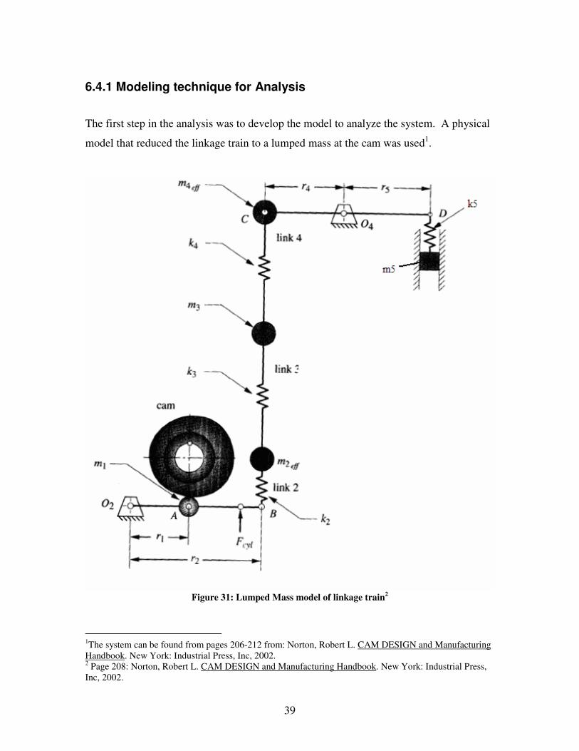
6.4.1 Modeling technique for Analysis
The first step in the analysis was to develop the model to analyze the system. A physical model that reduced the linkage train to a lumped mass at the cam was used1.
Figure 31: Lumped Mass model of linkage train2
1The system can be found from pages 206-212 from: Norton, Robert L. CAM DESIGN and Manufacturing Handbook. New York: Industrial Press, Inc, 2002. 2 Page 208: Norton, Robert L. CAM DESIGN and Manufacturing Handbook. New York: Industrial Press, Inc, 2002.

40
Figure 31 shows the “lollipop stick” approach used to model a linkage train. The original system consists of a cam follower lever, a connecting rod, a rocker and finally the tooling.
After developing this model, the next step was to find the effective mass and effective spring of the system felt at the cam. Reducing the system to a single effective mass and
effective spring at the cam is shown in Figure 32.
Figure 32: Lumped mass at the Cam
The next step was to define the position, velocity, and acceleration functions for the cam to be used in the model. A simple cam that consists of a rise, fall, and dwell was chosen
as the standard cam for the entire vibration analysis. The rise and fall are 0.024 meters and runs at 180 rpm. This cam was chosen as the standard cam for all the vibration
analysis because of its ease of programming in MathCAD and because it had a relatively large rise of 0.024 meters.

41
Figure 33: S, V, A functions for CAM
Figure 33 shows the equations3 used to define the position, velocity, and acceleration
functions. After defining the cam it was possible to simulate the vibrations of the system by solving the following equation4:
Equation 1: Vibration Differential Equation (10.9b)
The vibration equation consists of the natural frequency of the system, �, and � the
damping coefficient, which was assumed to be 0.05. S(t) and V(t) are the theoretical position and velocity functions defined in Figure 33. The actual mathematical model was
written using MathCAD and can be found in Appendix C.
3 Pages 57-124: Norton, Robert L. CAM DESIGN and Manufacturing Handbook. New York: Industrial Press, Inc, 2002. 4 Equation 10.9b page 278: Norton, Robert L. CAM DESIGN and Manufacturing Handbook. New York: Industrial Press, Inc, 2002.

42
6.4.2 Existing Linkage train information The purpose of the vibration analysis is to compare different linkage configurations in
order to determine which configuration has lower vibrations. It was necessary to have an initial configuration that modeled a current linkage train on the existing machine as the
benchmark for comparison. With the solid models that were received from Gillette, the necessary information needed to model our standard linkage configuration was readily available.
The initial cam follower lever’s information is based on part 36040er. The material used
for this model is AISI 1020 steel. SOLIDWORKS was used to calculate the mass of the part and mass moment of inertia about the point of rotation. To estimate the stiffness, the
Finite Element Analysis package within SOLIDWORKS, COSMOSexpress, was utilized. Figure 34 shows the boundary conditions used for the FEA of the part. The boundary
conditions of the part are those of a moment-supported overhung beam. The applied load is 1000 N. The deflection distribution results of the FEA are shown in Figure 35. To
estimate the stiffness of the link the applied load was divided by the deflection of the beam at the point of the applied load.
280mm
Figure 34: Boundary Conditions for FEA of 36040er

43
Figure 35: Displacement Distribution of 36040er
The connecting rod data is based from part 36040abl shown in Figure 36. From the model we found the length, mass and cross-sectional area of the connecting rod. In order
to determine the stiffness the following equation was used: Equation 2: Stiffness of beam in compression
LengthEAreaStiffness *=
Where Area is the cross-sectional area, E is the young’s modulus of the material and Length is the length (L) of the connecting rod, shown in Figure 36.

44
L
Figure 36: 36040abl The initial rocker lever information is derived by the same methods as the cam follower lever, but using part 36040fc. Again AISI 1020 steel is the selected material and
COSMOSexpress was used to find the stiffness of the link.
Figure 37: Finding Stiffness 4

45
Figure 38: Finding Stiffness 5
The rocker arm had to be analyzed as two cantilever beams; therefore the link contributes
two different stiffness terms, referred to as K4 and K5 in the MathCAD model in Appendix C, which are depicted in Figure 31. After calculating all the data for these links the model for the vibrations of the system was complete. This system is referred to as the “original system” for the remainder of the
report.
6.4.3 Sensitivity Experiment Identifying a “problem link” was an important step in the design process. By problem link it is meant the link or links that contribute the most to the simulated vibrations of the
system. If there is a specific link that is hurting the system then it is possible to make a design that can either eliminate or minimize the effects of that problem link. This section
will explain the methods used in this experiment.
The approach taken consisted of making a specific change to a particular link, while leaving all the other links in the system with the values of the original system. The goal
is to increase the overall stiffness of the system with minimal increase of mass; therefore

46
the specific changes that were applied to each link would increase the stiffness of that link.
Connecting Rod Iterations The first link that was examined was the connecting rod. The parameter changed was the
length of the link. Two iterations of our model were run using two different lengths of the connecting rod. The first iteration used a connecting rod length half the length of the
connecting rod from the original system. Since the length of the link was reduced to half, reducing the mass of the link by half would be appropriate. The second iteration
increased the length link to twice the length of the connecting rod from the original system. Again the mass of the link was increased to twice that of the original system’s
mass for the connecting rod.
Cam Follower lever Iterations The next two iterations of the model involved examining the effects of making changes to the cam follower lever while leaving the connecting rod and rocker the same as the
original system. The cam follower lever is in bending; therefore the critical dimension is the height.
Figure 39: Cam Follower lever Modified
Figure 39 shows the cam follower lever with two indicator lines on the top and bottom of the link. In order to stiffen the link the height dimension would need to be increased.
The two iterations done on this link involved increasing the height by first 5 mm and then by 10 mm. To distribute the mass symmetrically half the total change in height will be
distributed to the top of the link and half to the bottom. The mass of the link also is

47
increased as the total height of the link increased. Equation 3 was used to find the amount of mass that would be produced by the change in height.
Equation 3: Change in Mass DensitymHLengthmass *014.0**δδ =
Length is the length of the link, δH is the total change in height, and the 0.014 m refers to
the thickness of the link and the Density term the mass density of steel. This δmass is
then be added to the original mass of the link before alteration.
Increasing the total height of the part also results in a change in the area moment of
inertia, which affects the stiffness. For the purpose of this model we simplified the effect
of increasing the height by doing the following:
Since the area moment of inertia of a rectangular beam is found by: Equation 4: Area Moment of inertia
12* 3hbI =
Where b is the base dimension and h is the height. Given that all that is changing is the
height we can find the percent change in the area moment of inertia assuming b is 1: Equation 5: Original Area Moment of Inertia
12)*1(1
3hinitialI =
Equation 6: Resulting Area Moment of Inertia
12))(*1(2
3dHhinitialI +=
Equation 7: Change in Area Moment of Inertia
1)12(
IIIChange −=
We know that the stiffness of a beam in bending is: Equation 8: Stiffness of Beam in Bending
ICMK *=
Where M is the mass and C is the distance from the neutral axis to the outer edge and I is
the area moment of inertia. Area moment of inertia is more sensitive to changes in height since the height is to the third power and therefore the “I” is more dominant in the

48
stiffness equation compared to the C term. For this reason it is reasonable to estimate that with an increase for any given height the resulting K would be:
Equation 9: Resulting Stiffness )1(* ChangeKinitialKresult +=
K initial is the stiffness that was found from the FEA analysis of the link. The (1+Change) factor is accounting for the percent change of the area moment of inertia and how it
affects the stiffness. Therefore in the MathCAD model the (1+Change) factor is calculated depending on the change in height parameter and then it is multiplied by the
stiffness that was found from the FEA of part 36040er.
Rocker Lever Iterations The iterations that focused on understanding the sensitivity of the system due to changes in the rocker lever follow the same format as the iterations focusing on cam follower lever. Two iterations were run; the first increasing the total height of part 36040fc by 5
mm and then the second increasing the total height by 10 mm.
As with the height changes performed on the cam follower arm, the increased height of the rocker lever results in an increased mass which is found using Equation 3. The
change in mass was then added to the original mass of part 36040fc. Also the K4 stiffness and K5 stiffness were increased using the method described previously using
Equation 4 - Equation 9.
Final Iteration The final iteration performed involved making changes to all the links simultaneously. The changes included:
• Reducing that length and mass of connecting rod to half the those of the original
• Adding 5 mm to the total height of both the cam follower and rocker lever
Table 8 is a summary of the input data for the MathCAD for each of the seven iterations that were performed as well as the original system data.

49
Table 8: Summary of Iteration Input Data

50
6.4.4 Statistical Methods used
Data interpretation is an important aspect of any analysis. This sub-chapter will focus on the way in which the results of this vibration analysis were interpreted and compared.
In order to correctly compare the iterations against the original system’s performance it is
important to have a relative scale for comparison. The first step taken was to find the “noise” that each of the iterations produced. Noise refers to the difference between the
theoretical accelerations of the cam and the simulated accelerations of the system. The noise function is define as P(t):
Equation 10: Noise function ')'()()( tdisptAtP −=
A(t) is the theoretical acceleration defined in Figure 33 and “disp(t)’’ is the simulated
accelerations of the system. Once the P(t) function is defined it is necessary to resolve the function’s solutions for each given time step to a single value. This was
accomplished using the mean of the sum of the squares and then taking the square root, also known as the RMS method. The summation of the squares is divided by 330 to
obtain the average. There were 330 data points in the array of P(t). Equation 11: RMS equation
Once the RMS values for the original system and for each of the iterations were acquired the next step was to compare them. To compare the different configurations the percent
change of the RMS of the iteration from the RMS of the original system was calculated. Equation 12: RMS Percent Change
100*lRMSOrigina
onRMSiteratilRMSOrigina −

51
6.4.5 Results of Sensitivity Experiment The results of the sensitivity experiment provide insight into what links in the linkage
train contribute most heavily to the vibrations of the system.
RMS Comparison
0
0.2
0.4
0.6
0.8
1
1.2
1.4
1
Original System
System with ConRodhalvedSystem with ConRodDoubledCam FollowerLever+5mmCam FollowerLever+10mmRocker lever+5mm
Rocker Lever+10mm
C F and Rocker+5mm,Conrod Halfed
Figure 40: RMS Comparison Graph
Figure 40 shows the RMS values for the original system and for each of the seven iterations that were performed and the percent changes are shown in Figure 41.
Increasing the stiffness of the rocker lever affects the vibrations of the system far more than changes to the connecting rod or cam follower lever. Simultaneously making
changes in each of the links also results a much lower RMS value. Figure 41 better demonstrates the impact of making specific changes to the links of the system.

52
Percent Changes
-50
-40
-30
-20
-10
0
10
20
30
1
Perc
ent
ConRod Halved
ConRod Doubled
Cam Follower Lever+5mm
Cam FollowerLever+10mmRocker Lever+5mm
Rocker Lever+10mm
CF and Rocker +5mm,Conrod halfed
Figure 41: Percent Change Graph
The percent negative changes denote iterations with RMS values less than that of the
original system therefore having lower overall vibration noise. The iteration in which the connecting rod’s length and mass were reduced by 0.5, the RMS value was reduced by
14.2% of the RMS of the original system. When the connecting rod’s length and mass were doubled it resulted in an increase of the RMS value of 23.9% of the RMS of the
original system. Making changes to the cam follower lever impacted the system in the least dramatic way. Both iterations focusing on making the cam follower lever stiffer in
bending resulted in a 1.7% reduction of the RMS value. In the rocker lever, making changes to the link to increase the stiffness in bending resulted in much more dramatic
changes. When the overall height of the link was increased by 5 mm, there was a 26.0% RMS reduction and the iteration where the height was increased by 10 mm resulted in
44.9% reduction. Lastly making the specific changes, described in Final Iteration sub-chapter of the Sensitivity Experiment, to all the links resulted in a reduction of RMS
value of 39.5%.

53
From the results it can be concluded that the “problem link” for our linkage train is the rocker lever. Redesigning this link alone to increase its stiffness dramatically improves
the stiffness of the overall linkage. If it were possible to eliminate the need of having the rocker lever in the linkage train, the overall stiffness would be improved even more.
7.0 Final Design Description
Figure 42: Final Design’s Isometric View
The final design evolved after determining the advantages and disadvantages of the
current machines. A SOLIDWORKS model of the entire assembly of the new machine can be seen in Figure 42. With the machine’s many components, it was crucial to ensure
that the machine stayed as clutter free as possible to allow access by operators and mechanics. It was important to properly support camshafts, ground bars and linkage
systems, but equally as important not to “over support” the systems and cause a spider-web of bars, links, and weldments. To further understand the machine, the description
will break the machine down and describe its many components. Justifications for the decisions made can be seen in the Analysis chapter.

54
Upper Camshaft
Lower Camshaft
Upper & Lower Support PlatesConveyor
Groundbars
GroundbarsChassis Support Legs
Figure 43: Front and Side View of Assembly Machine
Figure 43 shows the front and right side of the machine; the support system of the upper camshaft and linkage systems can be seen in the right side view. The upper plates
provide support for the upper camshaft (60 mm diameter) and the (50 x 50 mm) ground bars. The camshaft diameter, spacing and number of supports needed was determined
through the camshaft analysis described in the Analysis chapter later in this report. The same is true of the lower camshaft and its cam and linkage systems. The support plates in
the lower half of the machine provide support for the lower camshaft (60 mm diameter) and ground bars (50 x 50 mm). The lower camshaft does not drive as many linkage
systems as the upper one because the tooling motion that the lower linkage system produces is not required at every station. Floor space for this machine has been reduced
by moving the back camshaft to the top. Appendix K contains additional figures of the final machine layout for clarification.

55
a b c
Cylinders
Vertical Motion Linkage
Horizontal Motion Linkage
Groundpoints
Weldment
Horizontal Motion Linkage
Cylinders
Groundpoints
Weldment
Horizontal Motion Linkage
Weldment
Cylinder
Groundpoints
Figure 44: a: Upper Linkage, b: Lower Linkage Right, c: Lower Linkage Left
The final concepts for the linkage configurations on the machine can be seen in Figure 44. The upper linkage system, Figure 44a, has two separate linkage systems and allows for a
vertical operation and a right side operation from a camshaft running above the machine and offset from center to the right. This offset helps to prevent grease and debris from
falling on the tooling station. Figure 44b shows the lower linkage A; it provides horizontal motion from the left side of the machine. Figure 44c shows the lower linkage
B; it provides horizontal motion from the left. Each system is set up to allow for tooling lockout. The linkages were all modified to increase stiffness by shortening the
connecting rods to reduce vibrations, to ensure cylinder lockouts, and to allow access by operators and mechanics. The analysis goal was to show that the new designs are more
effective and allow for increased productivity. The following section will look deeper into the design of each linkage and the key improvements that lead to increased stiffness and reduced vibration.
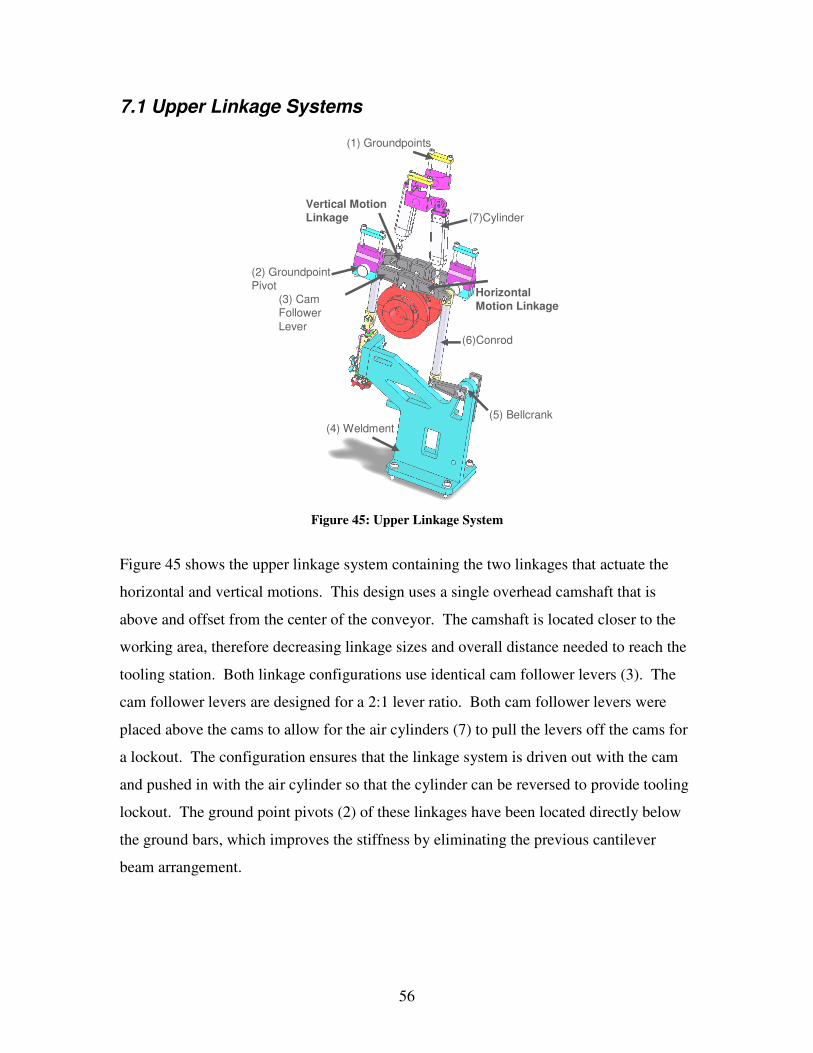
56
7.1 Upper Linkage Systems
(4) Weldment
(1) Groundpoints
(7)Cylinder
(5) Bellcrank
(6)Conrod
(3) Cam Follower Lever
(2) GroundpointPivot
Vertical Motion Linkage
Horizontal Motion Linkage
Figure 45: Upper Linkage System
Figure 45 shows the upper linkage system containing the two linkages that actuate the horizontal and vertical motions. This design uses a single overhead camshaft that is
above and offset from the center of the conveyor. The camshaft is located closer to the working area, therefore decreasing linkage sizes and overall distance needed to reach the
tooling station. Both linkage configurations use identical cam follower levers (3). The cam follower levers are designed for a 2:1 lever ratio. Both cam follower levers were
placed above the cams to allow for the air cylinders (7) to pull the levers off the cams for a lockout. The configuration ensures that the linkage system is driven out with the cam
and pushed in with the air cylinder so that the cylinder can be reversed to provide tooling lockout. The ground point pivots (2) of these linkages have been located directly below
the ground bars, which improves the stiffness by eliminating the previous cantilever beam arrangement.

57
The ground support setup can be seen in Figure 46. Ground bars 1 and 3 support the pivot brackets for the cam followers and ground bar 2 supports the air cylinders.
Groundbars
1
2
3
Weldment
Figure 46: Upper Ground bar Configuration
Figure 45 shows the linkages for the horizontal and vertical motions. Connecting rod (6) on the horizontal motion assembly is approximately 253 mm long, which is shorter then
the current connecting rod configuration. This connecting rod connects to an extended bell crank (5) to allow for the horizontal motion. The bell crank is supported by the
weldment (4), along its extension. Using a weldment ensures small ground deflections due to forces in the system. The weldment also provides support for the center tooling.
The vertical motion linkage system is simple and eliminated a link compared to the current design. The cam follower lever leads directly into the connecting rod and then to
the tooling. The connecting rod is approximately 172 mm long. With the linkage system for this tooling assembly decreased in size and increased in stiffness, the modified
linkages and ground stiffness was analyzed to find the overall improvement. The end effector of the new linkage was then compared to the allowed tolerance and proved to be
within the tolerance.

58
7.2 Lower Linkage Systems
(2) Cam Follower Lever
(3) Groundpoints
(4) GroundpointPivot
(1) Cylinder
(5) Conrod
(6) Bellcrank
(7) Weldment
(8) Ground Support Arm
Figure 47: Lower Linkage Configuration "A" Figure 47 shows configuration “A” of the lower linkage system that provides horizontal
motion for operations required on the opposite side of the belt. The camshaft is located 550 mm below the conveyor and is centered. The current camshaft is centered under the
conveyor, but is located closer to it allowing for a shorter connecting rod. The concept is identical to the current setup but changes have been made in the ground supports and
linkages. Cam follower lever (2) in this configuration has approximately a 2:1 lever ratio. It is slightly greater to allow for clearance past the upper ground support by connecting
rod (5). Once again the ground for the cam follower lever is directly below the ground point pivot (4). The ground support arm (8) extends to the second bottom ground bar to
act as a torsion bar. This improves the stiffness by reducing ground deflections due to torsion. The connecting rod is approximately 540 mm and leads into a stiffened bell
crank. Bell crank (6) is supported by a weldment (7) that is currently found on the machine. The use of this linkage system is to provide horizontal tooling motion that needs to come from the opposite side of the machine. Cylinder (1), which holds the cam
follower lever on the cam, can also provide a lockout position.

59
(8) Weldment
(5) Groundpoints
(2) Cylinder
(7) Bellcrank
(6) Conrod
(1) Cam Follower Lever
(4) GroundpointPivot
(3) Ground Support Arm
Figure 48: Lower Linkage Configuration "B"
Figure 48 shows configuration “B” of the lower linkage system; it actuates the horizontal
motion on the near side of the belt. This system runs off the same camshaft as configuration “A” in Figure 47 and utilizes the same ground bar configuration. The cam
follower lever (1) is identical to that in configuration “A”. The cam follower lever runs off of the top of the cam to allow for cylinder (2) lockout on the near side tooling motion.
Because the ground points (5) are closer together on the top side, the ground point pivot (4) is not directly over the ground point. Ground support arm (3) extends to attach to
both upper ground points and acts as a torsion bar to help compensate for the small cantilever effect at the ground pivot location. Connecting rod (6) is approximately 318
mm long and connects to bell crank (7). The support and pivot of the bell crank is provided by weldment (8).

60
Groundbars
Groundbars
Figure 49: Lower Ground bar Configuration Figure 49 shows the lower ground bar configuration. The ground bars are symmetric about the vertical axis. This allows the system to be configured from the bottom of the
cam or the top, linkage configuration “A” and “B” respectively. The upper ground bars are slightly closer so they do not interfere with the connecting rods that extend up to the
bell crank. All ground bars have been strengthened by switching from a rectangular cross section to a square. This helped to reduce the torsion caused at the ground supports. The
end effects of both lower linkage systems will be analyzed to ensure tolerance in the tool motion.

61
7.3 Link Redesign A sensitivity experiment was developed to determine what modifications to the linkage
trains would result in an increased effective stiffness of the system. Details of the sensitivity experiment were discussed in the Analysis chapter.
The results of the experiment made it apparent that redesigning the links themselves to
improve the stiffness translates to an increase in the effective stiffness of the linkage train as a whole. This section will discuss the modifications that were applied to each of the
links.
7.3.1 Cam Follower Levers The results of the sensitivity experiment showed that changes to the cam follower lever design do not translate to a significant increase of effective stiffness in the linkage train.
Even though making modifications to the current design of the cam follower levers would not have as much of an impact to the system as modifications to another link, it
was still decided that modifications to the cam follower levers would improve the system slightly and is therefore a viable approach. Figure 50 shows the side view of the cam
follower lever that is used in the vertical motion linkage as well as in the right horizontal motion linkages. One of the significant modifications that have been made to the link was to stiffen the link in bending.

62
140mm
280mm
43.1mm36mm
Figure 50: Cam Follower for Vertical and Right Horizontal Linkages Front View
This was accomplished by increasing the link height by 5 mm where the roller is positioned. The original height was 38.1 mm and tapered out. With a 5 mm increase to
the height, the stiffness in bending was improved by a factor of 10. The method of finding the bending stiffness was explained in the Vibration Analysis section of this
report.
Figure 51: Cam Follower for Vertical and Horizontal Motion Linkages Top View
14.6mm
50.5mm
20.5mm
11mm
42mm
53mm17.4mm
8 mm

63
Figure 51 shows the cam follower lever from the top. This view shows the two other changes that were incorporated into the new link design. The first modification deals
with how the link and roller follower will be assembled. Currently the assembly uses a cantilevered roller follower, which introduces a torque on the cam follower lever, in
essence twisting the link. This project did not analyze this assembly configuration to determine what the magnitudes of deflections were for the cam follower lever. Though
no analysis was completed it was assume that there would be some measurable deflections in the cam follower lever due the cantilevered roller follower configuration.
To eliminate any torque on the cam follower lever resulting from the cam coming into contact with the roller follower, the new link was designed to yoke the roller follower.
Roller Yoke Cavity
Roller FollowerCon Rod Yoke
Cavity
Con Rod
Figure 52: Cam Follower Assembly
Figure 52 shows the roller follower sitting inside the roller yoke cavity of the cam
follower lever. This configuration eliminates any torque that the cam follower would experience due to the forces of the cam on the roller follower. The same yoking
approach was taken in designing how the cam follower will be assembled with the

64
connecting rod. Again this yoking technique will eliminate any torque experienced by the cam follower lever due the dynamic forces of the connecting rod.
7.3.2 Bell Crank Design for Upper Linkages Making modifications to increase the stiffness of the bell cranks, referred to as the rocker lever in the Sensitivity Experiment section made a dramatic impact on the vibrations of
the linkage train in the sensitive experiment. The right horizontal motion bell cranks are split bell cranks and therefore are comprised of the parts, A and B which are shown in Figure 53 and Figure 54 and also a rod that connects them in torsion.
100mm
40mm
Figure 53: Right Horizontal Motion Bell Crank part A
40mm
120mm
Figure 54: Right Horizontal Motion Bell Crank part B
These new bell cranks were stiffened by adding 5 mm in height. The current bell cranks have a maximum height of 35 mm while the redesigned components have a maximum

65
height of 40 mm. This increase in height resulted in an increase in the bending stiffness for the link. The method used to find the stiffness in bending is explained in the
Vibration Analysis of New Design section.
7.3.3 Bell crank for Lower Linkages
Figure 55: Bell Crank
The redesigned bell crank for the lower linkages can be seen in Figure 55. More material
has been added to the bell crank. The original bell crank did not have the broad radius that now connects the two ends. This added material will increase the stiffness and
reduce any small deflections that may have been present.

66
7.4 Motor and Belt Configuration
(3) Servo Motor
(6) Gear Box
(7) Cam Box
(1) Upper Camshaft
(2) Lower Camshaft (5) Belt
(8) Belt Tensioner
(4) Belt Tensioner
Figure 56: Motor and Belt Configuration
Figure 56 shows the configuration of the motor and belts. The camshafts are powered by a servo motor (3) through timing belts (5) from the gear box (6). The gear box is
connected to the cam box (7), which drives the conveyor belt. Timing belts were chosen due to their synchronization capability and durability. Another option would be to have a
servo motor per camshaft, but this is not cost effective and could pose timing problems between the motors.

67
8.0 Vibration Analysis of New Design The vibration analysis for the newly designed linkage trains uses the same methods that
were described previously in the Vibration Analysis section.
As described in the preceding sections, the new design involves two camshafts; one camshaft is positioned underneath the indexing conveyor while the other camshaft is
positioned above the indexing conveyor. Again there are five different linkage train configurations which could be used to perform the two horizontal motions and the
vertical motion. Since all of these linkages will be used on the same machine the vibration levels for the over all machine are only as good as the worse linkage train on
the machine. For this reason the vibration analysis was completed for each of the five linkage train configurations:
• Vertical Motion Linkage
• Right Horizontal Motion Linkage A
• Right Horizontal Motion Linkage B
• Left Horizontal Motion Linkage A
• Left Horizontal Motion Linkage B
The description of each of these linkage trains can be found in Final Design Description chapter.
In order to find the necessary information to run our vibration model SOLIDWORKS
was used to find masses and mass moments of inertia. To estimate the stiffness of the links the finite element analysis package COSMOS Express was utilized. The deflection
distribution graphs for the new cam follower levers as well as the bell cranks can be found in Appendix I. The graph shown in Table 9 has all the data that is needed to run
the MathCAD vibration model.

68
Table 9: Final Linkage Data

69
The graphs of vibration noise (theoretical acceleration minus simulated acceleration) of
the system for 180 RPM can be found in Appendix K. Table 10 lists the RMS values of the deviation of simulated to theoretical vibrations for the original system and for each of
the newly designed linkage trains.
Table 10: RMS Values
The RMS value of the original system is included in the list to act as a reference for the acceptable vibration noise in the current machine. All of these RMS values were attained
running at a speed of 180 RPM. The amount of improvement in the vibration noise produced by the horizontal motion linkages is in the order of 80%. The surprising result is the RMS value of the vertical motion linkage. The vibration level is actually worse by
71.7%. This is an unexpected result. Looking at Table 11 it is can be seen that the vertical motion linkage has the highest effective stiffness.

70
Table 11: Effective Stiffness
The vertical motion linkage was designed to have a much higher effective stiffness and it was assumed that to produce the lowest levels of vibrations. After running the vibration
model that turned out to be false.
To address this issue the simulation model was run at different camshaft speeds to see if that had any effect on the vibration levels produced by the linkages. It became apparent
that this change had a dramatic effect on the vibrations of the system. Unfortunately, due to time limitations, it was not possible for more research of this phenomenon. A series of
iterations for each linkage configuration, running at different camshaft speeds, was performed. The iterations included running the model at camshaft speeds starting at 180
RPM and using an increment of 10 RPM up to 350 RPM. Table 12 lists the results of the iterations performed.

71
Table 12: RMS values for Varying Camshaft Speeds
Figure 57 is the graph of the RMS values for each of the five newly designed linkage
trains against camshaft speed. The graph is capped-off at 0.934 because that is the RMS value of the original system’s vibration noise. The assumption is that the simulated
acceleration RMS deviation from the theoretical acceleration can not exceed 0.934 since this deviation is currently an acceptable value.

72
RMS Values for Varying Camshaft Speeds
-0.066
0.034
0.134
0.234
0.334
0.434
0.534
0.634
0.734
0.834
0.934
180
200
220
240
260
280
300
320
340
RPM
RMS
Valu
e
Vertical Motion Linkage
Right Horizontal MotionLinkage ARight Horizontal MotionLinkage BLeft Horizontal MotionLinkage ALeft Horizontal MotionLinkage B
Figure 57: Graph of RMS values for Varying Shaft speeds
From the varying camshaft speed iterations it can be seen that running the newly designed linkages at 300 RPM would result in lower vibration than that of the original
system currently used. At this speed the maximum RMS value is 0.683 and is produced by the right horizontal motion linkage A.
Due to the time limitations it was only possible to do minimal research into what caused the recorded vibration phenomenon. Figure 58 shows the FFT graph for the standard
cam used for all the vibration analysis.

73
Figure 58: FFT Magnitude of cam at 180 RPM
The cam has natural harmonics which can cause vibrations in a linkage if the harmonic has the same frequency as the first natural frequency of the linkage. The frequencies of
the cam harmonics depend on the cam function. The actual way the harmonics of the cam interact with the natural frequencies of the linkage trains is not explored in this project. More research in this area is recommended.
Although the RMS values for all of the newly designed linkages are below that of the
original system, the resulting accelerations are much greater running the system at 300 RPM compared to 180 RPM. The maximum acceleration running the system at 180
RPM is 42.2 degs/s^2 while the maximum acceleration running at 300 RPM is 120 degs/s^2. This report does not examine the results of having such high accelerations due
to the camshaft speed. A full stress analysis should be completed in the future.

74
9.0 Conclusions and Recommendations The goal of this project was to design an in-line assembly machine that could run at 300-350 RPM. Focus was placed on reducing vibrations with stiffer and lower mass linkage
trains and reducing camshaft and ground deflections to increase accuracy.
One of the foci of the design process was minimizing the vibration noise of the linkage trains; therefore it was assumed that by increasing the specific stiffness of the system the
vibration noise would be reduced. The results of the vibration simulation model for each of the newly designed linkage trains showed that increasing the specific stiffness of a
system does not always guarantee a reduction of vibrations at a particular speed.
Designing links to be stiffer is the first step in being able to design a machine that has a higher operating speed, but this study shows that there are many other areas that should
be examined in order to take the design of a new machine to the next level of improvement. Understanding the relationship between the forcing frequency of the
system, operating speed, and the natural frequency of the linkage trains is a very important aspect.
Table 13: Natural Frequencies
Linkage First Natural Frequency
(Hz) Original System 646.6 Vertical Motion 2667 Right Horizontal A 1172 Right Horizontal B 1256 Left Horizontal A 1225 Left Horizontal B 1296

75
Table 13 shows the first natural frequencies of the original system and of each of the newly designed linkage trains. Notice that each of the horizontal motion linkages have
natural frequencies that are around the same value, while the vertical motion linkage has a natural frequency of twice that of the others. Referring back to Figure 57, the way in
which the RMS of the vibration noise for the vertical motion linkage behaves to the changes in operational speed is quite different from the other linkages while the four
horizontal motion linkages behave in a similar way to the changes of operating speed. Further work needs to be done in this area to understand this phenomenon. The vibration
sensitivity of the linkages with respect to changes in the camshaft speed seems to correlate with the case study known as: Analyzing Vibrations in Cam-Driven Automated
Assembly Machinery5. The case study examines the vibrations of an entire assembly machine and maps the vibration levels of the machine at different machine operating
speeds. This technique of mapping the entire system’s vibration levels for a varying operating speed would be the next logical step in this design to determine the optimal
operation speed.
The vibration experiments were all run using the same cam. It is possible to assume that a different cam would also affect the results of running the linkages at different speeds.
This assumption is viable because the harmonics of a cam depend on the contour. Each linkage most likely would have a specific cam function and therefore would have
different harmonics that would interact with the natural frequency of the linkage that the cam is driving.
The scope of the vibration analysis contained in this project was not able to address some
of these areas, and it is recommended that future research be in the areas of:
• Mapping the vibrations for an entire in-line assembly machine for varying
operating speeds
• Drive linkage trains using the actual cams used to perform the operation
• Full stress analysis for parts running at target operating speed. 5 Page 511: Norton, Robert L. CAM DESIGN and Manufacturing Handbook. New York: Industrial Press, Inc, 2002.

76
We also concluded that spacing between camshaft supports is a parameter independent of the machine length and dependent on camshaft diameter. For a 4000 mm long machine,
reasonable deflections were achieved with a combination of six supports evenly spaced (800 mm between supports) and 60 mm shaft diameter. With fewer than six supports, the
knee in the exponential curve is approached seen in Figure 25, drastically increasing camshaft deflection. More than six supports does not improve the system enough to
warrant another support and reduces operator and mechanic access. The current 60 mm diameter camshaft can be used in this set-up because deflection improvements with larger
diameters are not significant.
By using a 50x50 mm cross section for the ground bars, inaccuracies due to ground support deflections were reduced to an insignificant amount. Also, by modifying the
ground clamps so the cam follower pivots are located directly above or below the ground supports, the cantilever beam deflections of the current system were eliminated and
further stiffen the ground supports. The deflections and accuracies of the linkages analyzed are summarized below and shows
that the new ground bars significantly stiffen the system compared to the old one.
Table 14: Summary of Deflections
Ground Deflection Comparison New Bar 50x50 mm 0.016 mm Original Bar 30x50 mm 0.072 mm Camshaft Deflection 0.038 mm
Table 15: Summary of Tolerances
Summary of Tolerance +/- mm Top Horizontal Top Vertical New Bar 50x50 mm +/- 0.12 mm +/- 0.0915 mm Original Bar 30x50 mm +/- 0.20 mm +/- 0.148 mm

77
The deflection calculations were made assuming ten stations arranged uniformly along the machine. There may be cases which this number differs and we recommend
verification of these calculations depending on the machine configuration. Other assumptions were made to the best of our knowledge and based on information provided
to us. We recommend that they be verified for validity according to Gillette standards.
The final design incorporates many possible improvements to the current assembly machines. It suggests yoking link connections, an overhead camshaft, improved link
geometries, and considerations of access in order to reduce downtime. We recommend that further analysis and experiments be conducted in the areas we started to explore so
that future machines can incorporate them and perform with greater accuracy and speed.
78
10.0 Summary of Findings The next section presents a concise summary of this project. It includes the findings for the vibration analysis, the deflection analysis, and summarizes the final design’s key
features. Refer back to the text for more discussion of these key points.
Vibration Analysis
• Designing stiffer links is only one aspect in being able to design a machine with a
higher operating speed. o The relationship between the forcing frequency of the system, operating
speed, and the natural frequency of the linkage trains is must also be understood.
• Increasing the effective stiffness of a system does not always guarantee a
reduction of vibrations at a particular speed. In other words, low vibrations may occur at particular speeds
Deflection Analysis
• The spacing between camshaft supports is a parameter independent of the
machine length and dependent of camshaft diameter.
• For the analyzed machine with a length of 4000 mm, the best combination of support distance and camshaft diameter is:
o 6 supports evenly spaced (800 mm between supports) o 60 mm camshaft diameter
• Ground bars with a 50x50 mm cross section versus the original 50x30mm, significantly increases the stiffness of the linkage systems.
o The analysis shows that by switching from a 50x30 mm to 50x50 mm cross section, the accuracy is improved by an average of 40%.

79
Final Design Features Please refer to Figure 59 when reading the bulleted list. Appendix K includes additional images of the final design for further clarity.
• Two 60 mm diameter camshafts run along the length of the machine supported at six places (every 800 mm).
o One camshaft runs directly under the conveyor belt. The cams providing horizontal motion B are mounted on this camshaft.
o The second camshaft is located above and to the back of the conveyor belt. Cams providing the vertical and horizontal motion A are mounted on this
camshaft.
• The location of camshafts is the best compromise between optimal camshaft
locations for vibrations and length of linkage trains and functionality and access issues.
• Power is transferred from the gear box to both camshafts via synchronous belts so that both camshafts can be phased together.
• A servo motor is suggested for quick starts and stops and good speed control.
• All linkage trains are configured so that the tooling will retract from the nest in the case of a lockout.
• Yoking of links is used where possible to reduce horizontal space taken by the linkage and to eliminate cantilever effects.
• The new link geometries have increased stiffness.
• 50 mm square cross section ground supports are used rather then the 50x30 mm; this increases stiffness.

80
Upper Camshaft
Lower Camshaft
Upper & Lower Support PlatesConveyor
Groundbars
GroundbarsChassis Support Legs
Figure 59: Final Design

81
11.0 References AC Servo Motors 2005. Electric Motors Reference Center 23 September
2005 <http://www.electricmotors.machinedesign.com>
Chain and Belt Drive 1997. Power Transmission Design 12 September 2005 <http://www.emerson-ept.com/eptroot/public/schools/beltchan.pdf> Components for Drivelines 2005, Metal Chain. 12 September 2005
<http://machinedesign.com/ASP/viewBDEArticle.asp?page=&catId=373&strArticleFileName=/BDE/mechanical/bdemech1/bdemech1_8.html>
Cone Drive - Textron Model HP Double Enveloping Worm Gear Gearboxes. Akron Gear.
1 Oct. 2005 <http://www.akrongear.com/images/double-enveloping-worms.gif>. Cone Drive Model HP Double Reduction Dimensions. Akron Gear. 1 Oct. 2005
<http://www.akrongear.com/cone_drive_model_hp.htm>. DC Servo Motors 2005. Electric Motors Reference Center 15 September 2005 <http://www.electricmotors.machinedesign.com> Depweg, Frank A. et al. “Multiple Spindle Rotary indexing Machine Tool”. US Patent
4351096. Sep. 28, 1982. Hyponic – Hypoid Gear Technology. Industry Search 1 Oct. 2005
<http://www.industrysearch.com.au/products/viewrecord.asp?id=5734>. Maynard, Corey N. An Experimental Investigation of Phase Error due to Axial
Vibrations of High Torque Synchronous Belts. Diss. Worcester Polytechnic Institute, 2000.
Norton, Robert L. Design of Machinery third edition. New York, NY: McGraw-Hill
Companies, Inc. 2004. Norton, Robert L. Cam Design and Manufacturing Handbook. New Your, NY: Industrial
Press, Inc. 2002. Right Angle SK+. Alpha Gear. 1 Oct. 2005 <http://www.alphagear.com>. Right Angle SK+. Alpha Gear 1 Oct. 2005
<http://www.alphagetriebe.de/de/sk_plusus0805.pdf>. Swanson, Douglas L. et al. “Commonly Actuated in-line Assembly Machine”. US Patent
4292734. Oct. 6, 1981.

82
Swanson, Douglas L. “Modular Assembly Machine”. US Patent 6036003. Mar. 14, 2000. Yeo, Norman H. et al. “Assembly Machine”. US Patent 4313260. Feb. 2. 1982.

83
Appendix A: Background Research Researching existing designs of indexing machine chassis and tooling linkage configurations was performed for initial background research. The concentration was on
patents that involve designs of indexing machine chassis and tooling linkages.
Commonly Actuated in-line Assembly Machine6 The first patent that was discovered having relevance to our project is known as the
commonly actuated in-line assembly machine, US patent number 4,292,734. The machine was designed by Douglas Swanson and Norman Yeo. The design was granted an
US patent in 1981.
The design consists of a camshaft with a number of cams. The cams drive what Swanson refers to as “elongated tool plates”. These tooling plates are the tooling linkages that are
used to perform a specific task on the part. Figure 60 shows the front view of the design, while Figure 61 is a picture of the entire machine from the side.
6 Swanson, Douglas L. et al. “Commonly Actuated in-line Assembly Machine”. US Patent 4292734. Oct.
6, 1981.

84
Figure 60: Commonly actuated in-line assembly Machine
Figure 61: Side View of Commonly Actuated inline assembly machine
The intent of this invention was to improve existing in-line assembly machines. At the time most in-line assembly machines used two camshafts with separate tooling drive
mechanisms to provide the tooling motions for each tooling station.

85
Figure 62: Form closed cam configuration
Figure 62 is a picture of the closed form cam that was used for this design. The form
closed design reduces any necessary components needed to provide a force to keep the roller on the cam, therefore making the design even more compact. This is an interesting
design because it minimizes space required to house the machine.
This invention uses only one camshaft and has all the driving mechanisms built off of the cams on the single camshaft. The goal was to provide a more interchangeable, less
expensive and overall simpler in-line assembly machine.

86
Multiple Spindle Rotary Indexing Machine Tool7 The Multiple Spindle Rotary Indexing Machine Tool was designed by Frank A. Depweg and Edward A. Zukowski for White Consolidated Inc. The machine consists of a fixed
circular base with a column perpendicularly projecting upwards from the base. Upon the base is the circular indexing table. The machine indexes parts in a circular motion.
Independent of the primary indexing motion, the tooling work stations are driven by numerically controlled motors for x and y axis tool movement. Figure 63 shows a sided
view drawing of the design for the multiple spindle rotary indexing machine tool and Figure 64 shows the top view of the invention.
Figure 63: Multiple Spindle Rotary Indexing Machine Tool
7 Depweg, Frank A. et al. “Multiple Spindle Rotary indexing Machine Tool”. US Patent 4351096. Sep. 28,
1982.

87
Figure 64: Top view of Multiple Spindle Rotary Indexing Machine
The purpose of this invention was to improve the rotary indexing assembly machine. It improved upon the rotary indexing machine by allowing for more versatility. The
Multiple Spindle Rotary Indexing Machine did so by enabling threading and contouring operations to be complete and also increasing the precision from 0.0005in to 0.0001in.
The machine that our project focuses on is a linear indexing machine and while this
machine is rotary indexing we feel that it is important to be open any and all possibilities for the design of an indexing machine.
Modular Assembly Machine8 The modular assembly machine was designed by Douglas Swanson and the patent was granted in March of 2000. The design is fairly recent compared to the other designs we
looked into.
8 Swanson, Douglas L. “Modular Assembly Machine”. US Patent 6036003. Mar. 14, 2000.

88
The machine consists of a rigid platform; multiply modular supports that are identical, and linkage configurations that are used to receive product fixtures. It is interesting that
this design utilizes a chain driven linkage configuration. The idea of using chains to transfer power could be a possibility in our future design. A picture of the design can be
found in Figure 65.
Figure 65: Modular Assembly Machine
The main goal of this design is making the assembly more flexible or interchangeable. To accomplish this goal, the inventor decided to use multiple modular tooling stations
that can be quickly adjusted to accommodate the necessary configuration.
Assembly Machine9 The assembly machine design was created by Norman Yeo along with Douglas Swanson
and received a US patent in April of 1979. The design is similar to other patents we looked into. It includes a conveyor to move the part from a multiple of work stations.
The work stations support tooling and the tooling is timed with the motion of the conveyor. A picture can be found in Figure 66.
9 Yeo, Norman H. et al. “Assembly Machine”. US Patent 4313260. Feb. 2. 1982

89
Figure 66: Assembly Machine
The purpose of this invention was to resolve problems with the pre-existing design of an
in-line indexing machine. The major problem, as seen by the designer, was that the driving mechanism for the tooling stations was driven off the same camshaft that had the cams that controlled the actual indexing motion of the conveyor. Due this arrangement
the cams that controlled the indexing motion of the conveyor had a steep contour in order to be synchronized with the cams that drove the tooling mechanisms, the steep contour of
the cams resulted in excessive friction and loading difficulties. This new design of the assembly machine did not directly drive tooling mechanisms off the main shaft rather

90
intermittently drove a separate camshaft for the tooling mechanisms. To intermittently drive a camshaft for the tooling mechanisms the designer decided to use a separate
camshaft from the one that drives the indexing turret. Figure 66 shows the design; you can see a camshaft labeled 17. This camshaft is what drives the tooling plates using
cylindrical cams labeled 18 and 20 in the figure. The feature labeled 50 in the figure is the camshaft that is used to drive the indexing turret. The camshaft driving the tooling
plates is driven by the motor labeled 36. The designer decided in order to achieve the less steep contour of the cams it was necessary to eliminate the dwell phase from the cam
cycle. This was achieved by using either a second motor that has a greater starting torque than the driving motor or a clutch mechanism which would be used to stop the tooling
motion while the turret indexes nests to the next station. These features are what make the invention successful. Possibly using the idea driving tooling stations separate from
the indexing turret in our design could prove to be an interesting approach.
Patent Research Conclusions Most of the designs we analyzed were of the indexing machine as a whole. Our project
will be focusing on the linkages that drive the tooling for the machine. Though the patents did not directly relate to this aspect of the indexing machine we feel that
understanding the machine as whole will aide in achieving a more efficient tooling station configuration.
DC Servo Motors10
DC Servo motors are used in computers, numerically controlled machinery, or other applications where starts and stops are made quickly and accurately. In an indexing
machine, the quick stop is of interest due to occasional crashes. An immediate stop of the machine is required to save machine parts and products from damage.
10 DC Servo Motors 2005. Electric Motors Reference Center. 23 September 2005 <http://www.electricmotors.machinedesign.com>

91
Servo motors have lightweight, low-inertia armatures that respond quickly to excitation-voltage changes. They have very low armature inductance which further sharpens their
response to command signals. The rotor of a shell dc servo motor consists of “a cylindrical shell of copper or aluminum wire coils that rotate in a magnetic field in the
annular space between magnetic pole pieces and a stationary iron core.”
AC Servo Motors11
AC servo motors are essentially two-phase, reversible, induction motors modified for
servo operation. They have low inertia for fast starts, stops, and reversals because of their small diameter and high resistance rotors. These characteristics make them suitable for
applications requiring rapid and accurate responses. Also, their high resistance results in very linear speed-torque characteristics. The inherent damping of these motors decreases
as ratings increase therefore they are designed to have a reasonable efficiency at the sacrifice of speed-torque linearity.
Gear Boxes Due to motor size and space constraints, motor location in the design of the system is very important. Motor location will determine how the overall machine can be setup.
One important item in determining the motor location is the type of gear box that will be selected.
Locating the motor directly in line with the cam shaft is one option. Typically the gear
box used in this situation would be a planetary gear box. The planetary gear set is precise and allows low backlash. Using this type of gear box on a cam shaft running the entire
length of the machine will not be a problem and currently is the configuration on the blade assembly machine. An idea of the size of the gear box can be seen in Figure 67.
11 AC Servo Motors 2005 Electric Motors Reference Center 23 September 2005 <http://www.electricmotors.machinedesign.com>

92
Figure 67: Drawing of an Alpha Gear TP+ inline planetary gear box
Another approach to minimize overall size in the modular situation would be to use a right angled gear box that uses “innovative hypoid technology”12. These units, produced
by Alpha Gear, produce low backlash, low torsional backlash, an efficiency of 96%, and are designed for both cyclic and continuous operation. These specifications are similar to
the planetary gear box. Advantages are that the right angle configuration allows the motor to be placed lower on the machine and shortens the length of the camshaft, gear
box, and motor setup. This gear box is relatively small compared to a cone drive gear box which will be discussed next. A cut out of the hypoid gear box can be seen in Figure
68 and sample dimensions can be seen in Figure 69.
Figure 68: Hypoid Gear 90 degree Gear Box
12 "Right Angle SK+." Alpha Gear. 1 Oct. 2005 <http://www.alphagear.com>.

93
Figure 6913: Alpha Gear SK+ 90 degree Gear Box (mm)
Another approach to powering the modular design is a cone drive gear box. A cone drive
gear box has a double enveloping worm and worm gear. The double enveloping design allows for very low backlash compared to the typical worm and worm gear, due to its
high precision. The common worm and worm gear design provides a 1:1.5 gear teeth in contact with worm ratio, while the double enveloping provides contact between 1/8th of the total number of teeth. A drawing comparing a regular worm and worm gear and
double enveloping worm and worm gear can be seen in Figure 70.
Figure 7014: Typical and Double Enveloping Worm Gears
13 "Right Angle SK+." Alpha Gear. 1 Oct. 2005 <http://www.alphagetriebe.de/de/sk_plusus0805.pdf>.

94
The size of different cone drive gear boxes, produced by Akron Gear, can be seen in
Figure 71. The size of these gear boxes is greater than the hypoid gear boxes and they weigh more. Also, this approach is more expensive than the inline gear box.
Figure 7115: Akron Double Enveloping Worm Gear Size Chart
14 "Cone Drive - Textron Model HP Double Enveloping Worm Gear Gearboxes." Akron Gear. 1 Oct. 2005 <http://www.akrongear.com/images/double-enveloping-worms.gif>. 15 "Cone Drive Model HP Double Reduction Dimensions." Akron Gear. 1 Oct. 2005 <http://www.akrongear.com/cone_drive_model_hp.htm>.

95
Power Transfer Mechanisms Gears16
Gears are the most durable, rugged, and efficient way of transferring power. They are
chosen for heavy loads, long trouble-free life, but are more expensive than belt or chain drives. The main use for gears is to provide a variable output speed from a constant-
speed power source.
Chains
All drives can be engineered and adapted; however, chains usually do not have capacities or service lives equal to those of gears. When compared to belts, chains offer advantages
in capacity and service life at temperature extremes. Chains also provide positive drive ratios. Some problems that exist with chains include the need for chain tighteners to
increase the number of links engaged on the sprocket and to reduce chain backlash. Because the chains are in straight segments, when the chain goes around the sprocket,
chordal action takes place. The result is that even though the chain is traveling at constant velocity along its straight path, it does not have constant angular velocity when
going around the sprocket. The following are some of the advantages and drawbacks of chains17.
16 Components for Drivelines 2005. Metal Chains. 12 September 2005 <http://machinedesign.com/ASP/viewBDEArticle.asp?page=&catId=373&strArticleFileName=/BDE/mechanical/bdemech1/bdemech1_8.html> 17 Chain and Belt Drive 1997. Power Transmission Design. 12 September 2005 <http://www.emerson-ept.com/eptroot/public/schools/beltchan.pdf>

96
Advantages of Chains over Belts
a. No slip between chain and sprocket
b. Negligible stretch, allowing for high loads c. Long operating life
d. Can operate in hostile environments e. Long shelf-life
Chain Drawbacks
a. Noise is usually higher than with belts or gears, except for the inverted tooth chain
b. Chain drives can elongate due to wearing of link and sprocket teeth contact surfaces.
c. Usually limited to lower-speeds compared to belts d. Sprockets may need replacement due to wear
Several types of metal chains exist, the ones we researched are; roller chains, double
pitch, inverted silent tooth, offset sidebar, detachable, pintle and welded steel. They each suit different precision requirements and load capacities.

97
• Roller Chain
This is the typical chain seen on bicycles and other low precision machines. It is
used throughout industry and has been rated up to about 500 hp for single stranded chains and up to 2000 hp for four strand chains. Flexure joints in roller
chains contain pins that pivot inside the roller bushings. The pins are usually press-fit into the pin link plates and roller bushings are press-fit into roller link
plates. A free-turning roller encircles each bushing to provide rolling engagement and contact with sprocket teeth. See Figure 72.
Figure 72: Roller Chain
• Double Pitch
A double pitch chain is essentially the same as a roller chain, but the pitch
(distance between flexing joints) is doubled, allowing it to function well when the distance between axes is large. It has comparable load capacity, but it is lighter
and less expensive. It is designed for less rigorous conditions than roller chains and has been rated up to 9.5 hp. See Figure 73.

98
Figure 73: Double Pitch
• Inverted Silent tooth
Inverted silent tooth chains are more expensive, however, they operate smoothly,
quietly, and dependably in rigorous applications. It is used as a power takeoff from the prime mover in heavy equipment and some automobiles. Some high
precision engines also use this chain for timing of camshaft drives. See Figure 74
Figure 74: Inverted Silent Tooth
• Offset Sidebar
These are the most expensive precision chains even though they are less precise
than inverted silent tooth chains. They are more suitable for outside applications because they are more tolerant of dirt, debris, and misalignment. These chains are
very rugged and are typically used in construction machinery. See Figure 75

99
Figure 75: Offset Sidebar
• Detachable
These chains are commonly used in farm equipment and are effective at
transmitting power up to 25 hp at 350 fpm. They are not very, but they do not require lubrication and can be separated at any point without using special tools.
See Figure 76.
Figure 76: Detachable Chains
• Pintle and welded steel
Pintle and welded steel chains have the same characteristics as the detachable chains, but they are designed for more rigorous service and are rated to operate up to 40 hp at 450 fpm.

100
Belts
According to machinedesign.com, belts provide the best overall combination of design flexibility, low cost and maintenance, ease of drive assembly, and space savings when compared with chains and gears.
Belts need to be tensioned between axis centers for performance which may lead to over/under tensioning problems. They also have an inevitable vibration in the straight
section between centers. This is due to the acceleration belts experience when going around the pulleys. Even though belts travel with constant velocity during their linear
path, they experience centripetal accelerations when they go around the pulleys. The sudden transfer from centripetal acceleration to zero acceleration at the tangent points
gives infinite jerk, which causes vibration in the belt. However, belts are designed to minimize this effect.
Advantages of Belt Drives
1. No lubrication is required 2. Maintenance is minimal and infrequent
3. Belts dampen sudden shocks or changes in loading 4. Quiet and smooth operation
5. Pulleys are usually less expensive than chain drive sprockets and exhibit little wear over long operations
Disadvantages of Belt Drives
1. Endless belts usually cannot be repaired, but instead must be replaced
2. Slippage can occur when tension is not checked frequently, also, wear of the belt can require re-tensioning
3. Extreme environments can damage the belts, increasing slip 4. Length of endless belts cannot be adjusted
5. Access to the end of shafts is required for replacement
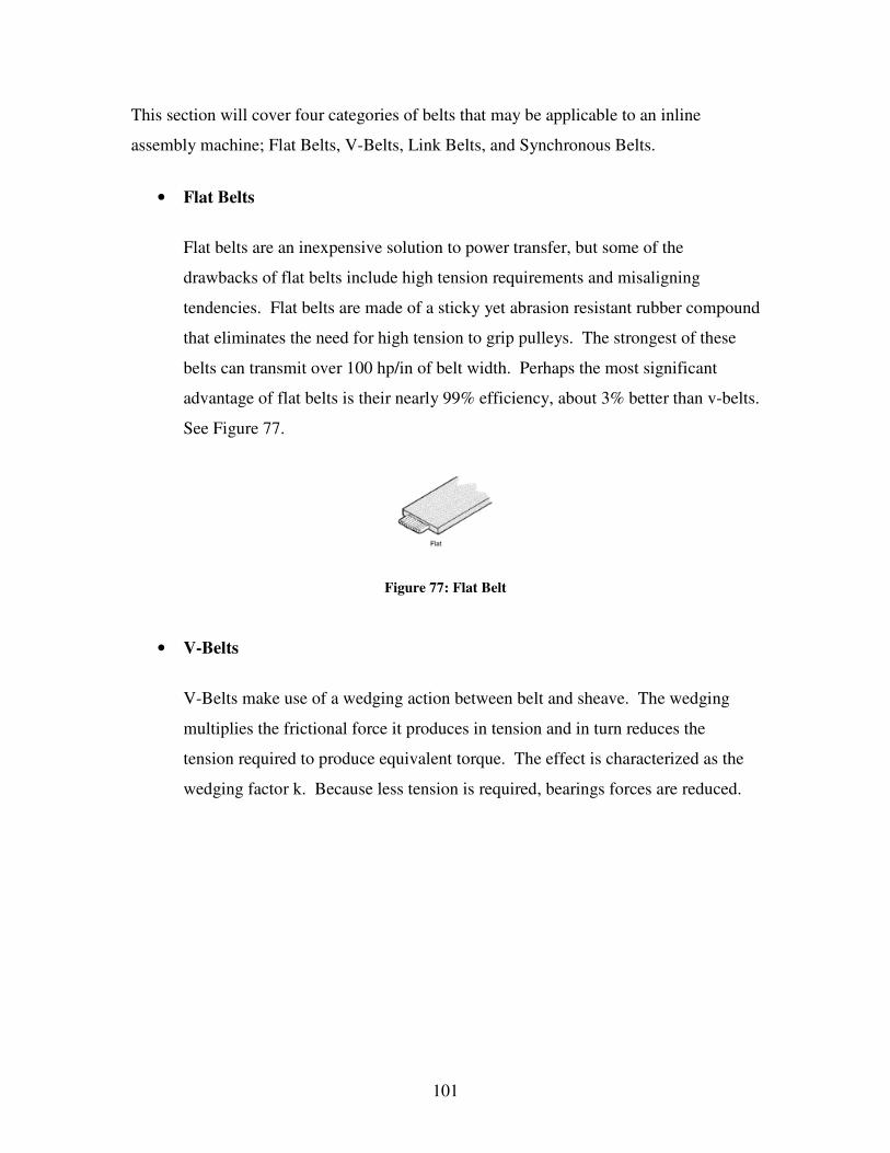
101
This section will cover four categories of belts that may be applicable to an inline assembly machine; Flat Belts, V-Belts, Link Belts, and Synchronous Belts.
• Flat Belts
Flat belts are an inexpensive solution to power transfer, but some of the drawbacks of flat belts include high tension requirements and misaligning
tendencies. Flat belts are made of a sticky yet abrasion resistant rubber compound that eliminates the need for high tension to grip pulleys. The strongest of these
belts can transmit over 100 hp/in of belt width. Perhaps the most significant advantage of flat belts is their nearly 99% efficiency, about 3% better than v-belts.
See Figure 77.
Figure 77: Flat Belt
• V-Belts
V-Belts make use of a wedging action between belt and sheave. The wedging
multiplies the frictional force it produces in tension and in turn reduces the tension required to produce equivalent torque. The effect is characterized as the
wedging factor k. Because less tension is required, bearings forces are reduced.

102
There are several categories of V-belts; classical multiple v-belts, narrow v-belts, v-ribbed belts, and the joined v-belts.
a. Classical multiple V-belts offer the broadest range of power ratings and are usually the first type of belt drive considered. These belts are heavy
duty, generating high centrifugal forces that place low limits on top speed. See Figure 78.
Figure 78: Classical V-Belt
b. Narrow v-belts increase the belts total power capacity by having a greater depth to width ratio, which places more of the sheave directly under the
reinforcing cord. They provide the highest power in the smallest package. See Figure 79.
Figure 79: Narrow V-Belt
c. V-Ribbed Belts are essentially flat belts with v-ribs. Because the v-ribs bottom out, there is no wedging factor. However, it reduces tensioning
required by flat belts by about 20% and the ribs eliminate tracking issues. The belt performs well in high speed ratios with a reverse-bend idler. See
Figure 80.

103
Figure 80: V-Ribbed Belt
d. Joined V-belts reduce turnover in the pulley grooves due to pulsating loads. Various v-belts are joined together by a top band, fusing them into
a single broad belt. See Figure 81.
Figure 81: Joined V-Belt After further research, it was found that because v-belts cannot guarantee synchronizing
and phase, they will not be a viable solution. The camshafts on the inline assembly machines must be synchronized together to ensure the assemblies are completed
accurately and on time.

104
• Link Belts
Link Belts are made of a composite of textile urethane plies, and the links are
connected by a rivet or spade end twisted through the next link. Their major advantage is reduction of downtime because matched sets of the correct length
belts are always available and can be joined to the rest of the belt at the machine. Other advantages are oil and water resistance, vibration damping, and an extended
temperature range. Some disadvantages include high cost of new materials and generation of static charges.
• Synchronous Belts
Also known as timing belts, they have a toothed profile that interlocks with grooved pulleys. This provides the same positive engagement that chains and
gears provide. They are reinforced with various materials, but most common reinforcements are steel, fiberglass, and aramid. According to machinedesign.com and other studies, synchronous belts may be the most
efficient form of power transmission short of direct drive. They can sustain high loads and some common applications are in power saws, motorcycles, and
vacuum-cleaner brushes.
The main drawbacks are high cost and demand for accurate alignment of pulleys.
Most synchronous belts find use on highly engineered and mass-produced drives. See Figure 82.

105
Figure 82: Synchronous Belt Workspace Ergonomics When designing machinery, functionality and accessibility must both be considered. In the blade assembly machines, the operator must be able to maneuver around the linkage
system to remove jams or address potential problems. Mechanics need clear access to cams, followers, linkages, and connecting rods for maintenance.
Figure 83 and Figure 84 show the average dimensions of males and females of the U.S.
Army. Standing vertical height and arm length are important when designing how high and how far away the workspace will be relative to the operator. Spacing of the
equipments must be considered to allow for hands to get in between the cams and linkages and work on the system. One of the goals for this project is to have a compact
design, but too high level of compactness may result in a congested work space.

106
Figure 8318: Selected Anthropometric Measurements
Figure 8419: Selected Anthropometric Measurements
The linkage system must be in the usable workspace of the operator, and there is a manual area and a visual area when both sitting and standing. Figure 85 and Figure 86
show this area while sitting and standing. The mechanics work on these blade assembly 18 Burgess, John H. Designing for Humans: The Human Factor in Engineering. Princeton, NJ: Petrocelli Book, 1986. pg. 10 19 Designing for Humans: The Human Factor in Engineering, pg 11

107
machines repeatedly and must be able to work comfortably standing, sitting, or a combination. The designs should accommodate the largest percentile of human
dimensions.
Figure 8520: Standing Workspace Measurements
Figure 8621: Sitting Workspace Measurements
20 Designing for Humans: The Human Factor in Engineering, pg 61 21 Designing for Humans: The Human Factor in Engineering, pg64

108
Appendix B: MathCAD & Dynacam Model for Camshaft Analysis
Each linkage system upon the blade assembly machine performs a different operation and therefore has a different cam for the different motion. The time/rise ratio on the cam will
determine the amount of force and torque applied to cam during different times of rotation. These force and torque values are required to perform the cam shaft analysis.
With the drawings for each cam supplied from Gillette, the time/rise ratios were found
and each cam was analyzed using DYNACAM. Each cam was put into DYNACAM as a radial, oscillating, roller cam. To perform the dynamic analysis, the effective mass,
spring constant, and spring preload must be determined. The effective mass was found during the vibration analysis and was 10.361kg. The spring preload of the system, 450N,
was found by performing an analysis of the air cylinder and a house air pressure of 80psi. The spring constant was arbitrarily set at 1N/m as this can be regulated with the air
cylinder. The cam with the worst time/rise ratio also proved to have the greatest values for force and torque. With a 10.092mm rise over 40deg, the maximum force was 886 N
and maximum torque was 17 N*m. The graphs can be seen in Figure 87. This worse case scenario was used for the analysis of the camshaft.
Figure 87: Force and Torque Graphs

109
The program used to determine the maximum bending and the torsional deflection of the camshaft was done using MathCAD. The following program is for design 4, with a 60
mm camshaft and hot rolled 1045 steel. This is the iteration the new design uses. Note that all calculations are done in the SI system using Newton, meter, and kilogram.

110

111

112

113

114

115

116

117
Appendix C: MathCAD model used for Vibration Simulation

118

119
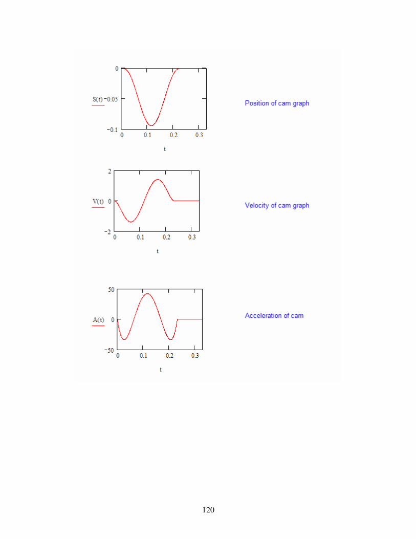
120

121

122
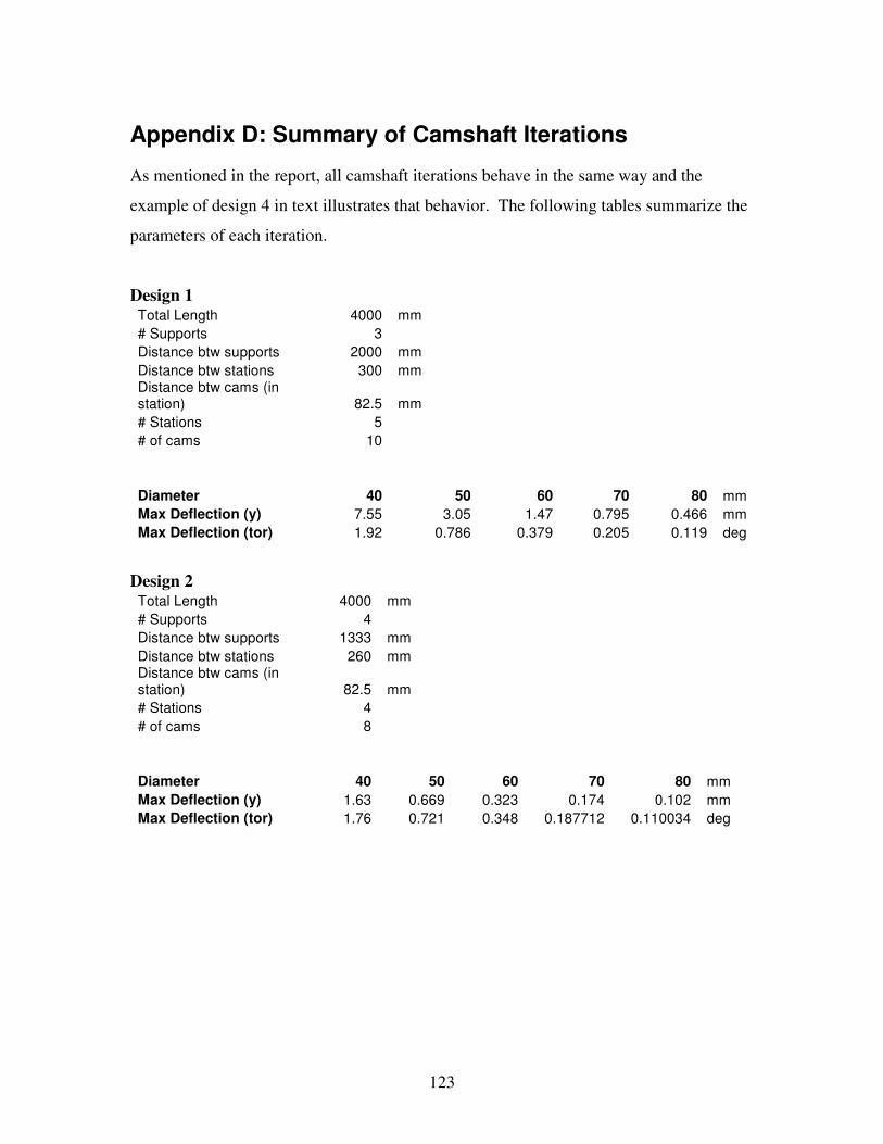
123
Appendix D: Summary of Camshaft Iterations As mentioned in the report, all camshaft iterations behave in the same way and the example of design 4 in text illustrates that behavior. The following tables summarize the
parameters of each iteration.
Design 1 Total Length 4000 mm # Supports 3 Distance btw supports 2000 mm Distance btw stations 300 mm Distance btw cams (in station) 82.5 mm # Stations 5 # of cams 10 Diameter 40 50 60 70 80 mm Max Deflection (y) 7.55 3.05 1.47 0.795 0.466 mm Max Deflection (tor) 1.92 0.786 0.379 0.205 0.119 deg
Design 2 Total Length 4000 mm # Supports 4 Distance btw supports 1333 mm Distance btw stations 260 mm Distance btw cams (in station) 82.5 mm # Stations 4 # of cams 8 Diameter 40 50 60 70 80 mm Max Deflection (y) 1.63 0.669 0.323 0.174 0.102 mm Max Deflection (tor) 1.76 0.721 0.348 0.187712 0.110034 deg

124
Design 3 Total Length 4000 mm # Supports 6 Distance btw supports (uneven) 950 mm Distance btw stations 260 mm Distance btw cams (in station) 82.5 mm # Stations 3 # of cams 6 Diameter 40 50 60 70 80 mm Max Deflection (y) 0.42 0.172 0.083 0.045 0.026 mm Max Deflection (tor) 1.82 0.748 0.361 0.195 0.114 deg
Design 4 Total Length 4000 mm # Supports 6 Distance btw supports 800 mm Distance btw stations 300 mm Distance btw cams (in station) 82.5 mm # Stations 2 # of cams 4 Diameter 40 50 60 70 80 mm Max Deflection (y) 0.193 0.079 0.038 0.026 0.012 mm Max Deflection (tor) 1.919 0.786 0.379 0.205 0.120 deg
Design 5 Total Length 4000 mm # Supports 7 Distance btw supports 666.67 mm Distance btw stations 260 mm Distance btw cams (in station) 82.5 mm # Stations 2 # of cams 4 Diameter 40 50 60 70 80 mm Max Deflection (y) 0.101 0.041 0.019 0.011 0.006 mm Max Deflection (tor) 1.65 0.675 0.326 0.176 0.103 deg

125
Appendix E: MathCAD Model of Ground Deflections The program used to determine the maximum bending and the torsional deflections of the ground was also done using MathCAD. The following program is for the ground bar on
the machine with a square cross section 50x50 mm. It is almost an identical program as was used to find the deflections of the camshaft.
Note that all calculations are done in the SI system using Newton, meter, and kilogram.

126

127

128

129

130

131

132
Appendix F: Determining Ground Support Forces In order to determine the forces for the ground deflection analysis, the cam follower was analyzed. Figure 88 shows a close up of the cam follower in the assembly and Figure 89
shows its FBD. R1 is the force needed for the model. A conservative estimate is made by assuming the m*a force at point D is acting down, which will result in a larger R1.
Figure 88: Close up of Cam Follower
R1 R2
P
M*a.d
y
xBA C D
Figure 89: FBD of Cam Follower
The variables to be solved for are the effective mass at point D and the acceleration at the point. Summing the forces in the y direction and moments about A allows R1 to be
calculated. The effective mass for this location was found using the program in Appendix C and is equal to 2.143 kg. The acceleration was found using cam drawing

133
number 36040ZS because it has one of the worse time vs. rise ratio of the cams provided to us by Gillette. Using Dynacam, the acceleration at point B where the cam is in contact
with the cam follower was found. Using the following relationship, the acceleration at point D was found. The acceleration at point B a distance 140 mm from point A is
19,076 deg/sec^2, so to find the acceleration at point D:
280140076,19 a=
“a” being the acceleration at point D, 280 mm from point A. The MathCAD program used to solve for R1 is shown below and corresponds to the FBD in Figure 89.

134
Appendix G: Determining the Torsional Deflection of the Ground Bar In order to find the torsional deflection of the ground bar, cam number 36040ZS was used for the analysis. The same Dynacam model used to find the acceleration of the cam
follower was used to find the maximum force the cam exerted on the cam follower. Refer to Figure 90 for the following discussion. Because the cam touches the roller on
the cam follower at point B, the effective mass of the linkage at point B was found first. Given the spring constant of 1 N/m and a preload of 450 N, which were found in
Appendix B, Dynacam was used to find the maximum force and pressure angle to find the force contributing to torsion in the ground bar.
R1 R2
P
M*a.d
y
xBA C D
Figure 90: FBD of the Cam follower
The result was a normal force of 820 N and a pressure angle of 15.2 degrees. Knowing
the pressure angle (phi) and the normal force (Fn), the force in the x direction was found. See Figure 91.
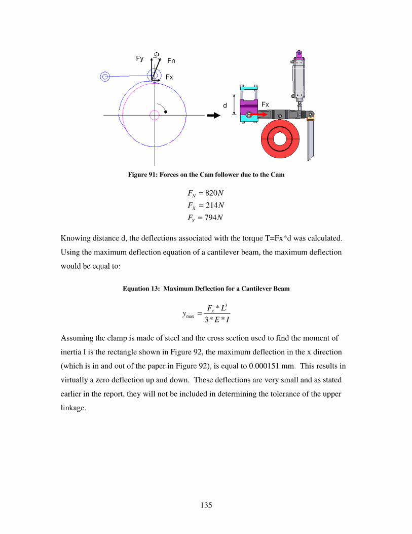
135
d Fx
Fy Fn
Fx
�
Figure 91: Forces on the Cam follower due to the Cam
NFNFNF
Y
X
N
794214820
===
Knowing distance d, the deflections associated with the torque T=Fx*d was calculated.
Using the maximum deflection equation of a cantilever beam, the maximum deflection would be equal to:
Equation 13: Maximum Deflection for a Cantilever Beam
IELFy x
**3* 3
max =
Assuming the clamp is made of steel and the cross section used to find the moment of inertia I is the rectangle shown in Figure 92, the maximum deflection in the x direction
(which is in and out of the paper in Figure 92), is equal to 0.000151 mm. This results in virtually a zero deflection up and down. These deflections are very small and as stated
earlier in the report, they will not be included in determining the tolerance of the upper linkage.

136
20 mm
100 mm
Figure 92: Conservative Cross Section of Clamp

137
Appendix H: Initial Design Concepts This appendix will further explore design concepts 2, 3 and 5. The camshafts in each
design have a diameter of 60 mm and the cams all have a diameter of about 200 mm. The purpose of the following models is to provide a clearer picture of the design concepts
in order to identify further strengths and weaknesses of each of the designs.
Please note that the description of the designs and the possible design variations was conducted when a modular approach to the design was still a viable solution. The ideas
behind the designs described were modified to the fit our new goal statement and functional requirements.
Configuration Possibilities for Modular Designs Notice that within each of the concepts that will be explained, different cam
configurations exist. They will be distinguished from each other as Case 1 through Case 5. Within each case, sub-configurations exist. The end of the written description
includes a table summarizing each case with respect to their number of camshafts, motors, and belts. Please refer to Error! Reference source not found..
Configuration Possibilities with Two Camshafts
Case 1: Two continuous camshafts parallel to indexing motion a. One motor driven camshaft with the second camshaft driven by a timing belt
or a silent tooth chain from the main shaft. b. Two motors, one for each camshaft.
Case 2: One continuous camshaft with additional sub-shafts for each station parallel to
indexing motion a. Sub-shafts driven by the continuous camshaft with timing belts or silent tooth
chains. b. Sub-shafts directly driven by individual motors
Case 3: Each station has two individual camshafts parallel to indexing motion

138
a. One motor driven camshaft with the second camshaft driven by a timing belt or a silent tooth chain.
b. Two motors, one for each camshaft.
Configuration Possibilities with One Camshaft Parallel to Indexing Motion Case 4:
a. One motor with camshafts coupled together. b. One motor driven camshaft per station (multiple motors).
Configurations Possibilities with Transverse Camshafts Case 5:
a. One transverse motor driven camshaft per station (multiple motors).
b. A line shaft running along the entire machine using a worm drive or a hypoid gear driving the transverse camshaft.
Table 16: Summary of Camshaft Configurations
Assuming Six Stations
Cases Sub-Cases
# of Camshafts
# of Motors
# of Belts/Chains
1a 2 1 1 Case 1: Two continuous camshafts. 1b 2 2 0
2a 7 1 6 Case 2: One continuous
camshaft with additional sub-shafts per station. 2b 7 7 0
3a 12 6 6 Case 3: Each station has
two individual camshafts. 3b 12 12 0
4a 6 1 0 Case 4: Single Camshaft. 4b 6 6 0
5a 6 6 0 Case 5: Transverse Camshaft. 5b 7 1 0

139
Refined Design 2 – Single Overhead Camshaft The first design that will be discussed is design 2 shown in Figure 93 below. This
concept utilizes one camshaft to drive all three tooling motions.
1
23
5
4
6
Figure 93: Isometric View of Design 2
The single overhead design is shown with three motions, the front horizontal motion, the back horizontal motion, and a vertical motion. The vertical motion has a 2-1 lever ratio,
the back horizontal motion has a 2-1 ratio, and the front horizontal motion has a 1-1 ratio. This concept was refined to maximize the commonalities among the links and in order to
do so, the camshaft and the two ground bar locations were vertically aligned with the camshaft as seen on Figure 94. This not only increased the commonalities among the
links, but allowed for a cleaner support structure that will be discussed later. Refer to Figure 93 for the following references. Links 1, 2, and 3 are all of the same length of 280
mm. Links 4 and 5 are also of the same length of about 290 mm. Lastly, the length of link 6 is 218 mm.

140
Ground 1
Ground 2
Camshaft
Figure 94: Side View of Design 2

141
The support structure for design 2 is shown in Figure 95. Because the overhead cam is located slightly towards the back of the machine, the structure to support the ground bars,
camshaft, and motor is designed to attach only to the back base plate leaving the front of the machine open. This requires that the current base plate be widened for strength. The
side to side dimensional accuracy of the structure is accomplished by having two tie bars that maintain the distance between the two support structures. The structure’s front to
back dimensional accuracy is maintained by the notch on the back of the support structures. The motor mount is attached to one of the support structures and is located in
the back of the machine to allow for easy access. Lastly, the ground clamps locate the side to side location of the ground bars.
DC Servo Motor
Support Structure
Tie Bars
Base
Ground Clamps
Gear Box
Figure 95: Perspective View of Design 2 Support Structure

142
Figure 96 illustrates Design 2 when the support structure and the cam-linkages are assembled together.
Figure 96: Perspective Views of Design 2
As mentioned earlier, the single camshaft configuration has two configurations. It can be
completely modular with every station having its own DC Servo motor and its own camshaft as shown in Figure 97 , or it can be semi-modular with one DC Servo motor
driving the entire system with every station’s camshaft coupled together with metal bellow couplings, shown in Figure 98. Note that the module stations are tied together
with horizontal ties to increase the stiffness of the system.

143
Figure 97: Design 2 - Individual Camshafts and Motors
Figure 98: Design 2 - Coupled Shaft with one Motor
The single overhead camshaft concept has both its advantages and disadvantages. One
advantage is that with one camshaft, there is no need to worry about transferring power from one camshaft to another. Also, by only having one camshaft, the support system
only has to pick up one shaft and makes for a clean compact system. One disadvantage of having one camshaft is the side to side constraint. Because the cams can be mounted
to only one camshaft, the configuration will allow for a maximum of 3-4 cams per station given the current average distance between tooling stations of 10-15 inches.
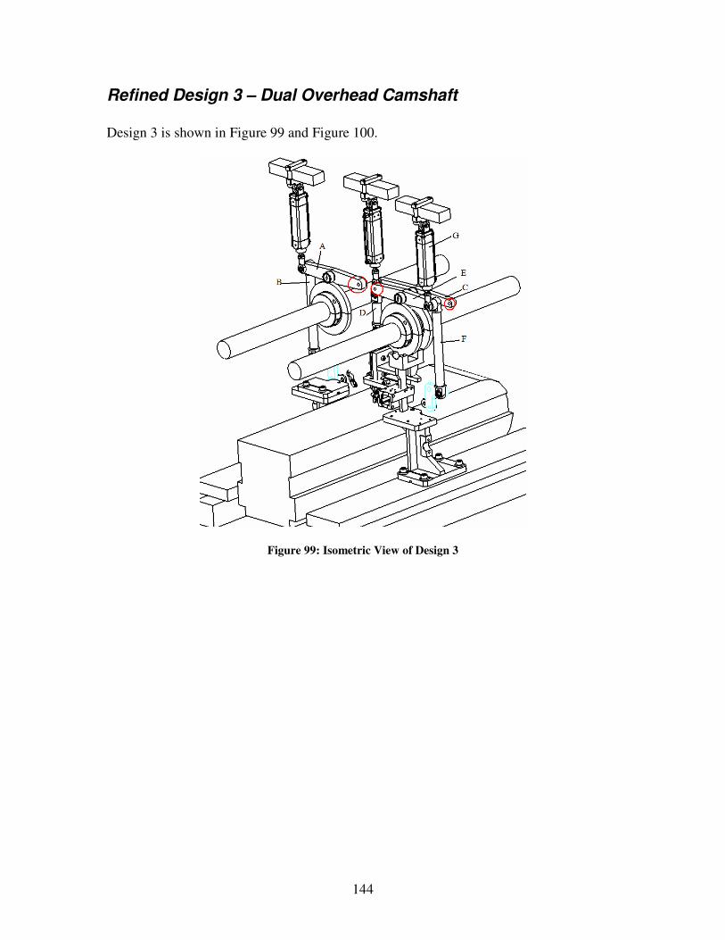
144
Refined Design 3 – Dual Overhead Camshaft Design 3 is shown in Figure 99 and Figure 100.
Figure 99: Isometric View of Design 3

145
Figure 100: Front View of Design 3
From Figure 99 and Figure 100 you can see important linkage components labeled. Components A, C and E are identical and both have a length of 250 mm. Components B
and F are both identical connecting rods with a length of 300 mm. Component D is the connecting rod for the vertical motion and has a length of 121 mm. A problem area for
this design is again circled in Figure 99 and Figure 100. This time only the ground locations for the linkages are the problem. The ground locations for components G, air
cylinder, are in a common location.
After further design of this concept we were able to construct the support structure that would be used to support the two camshafts and the grounding bar for the cam followers
and air cylinders shown in the following figures.
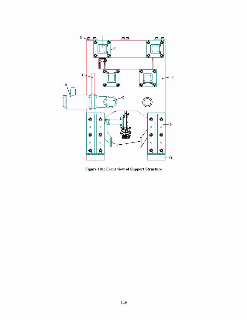
146
Figure 101: Front view of Support Structure

147
Figure 102: Side View of Support Structure
Figure 101 and Figure 102 show the design with the supporting structure. Component A is a DC servo motor that will be used to drive the camshaft while the second camshaft is
driven by a belt drive labeled K in Figure 102. In Figure 101 the component labeled D is a worm gear that will convert the power from the DC servo motor 90 degrees to drive the
camshaft. Feature C is the support bracket for the motor and worm gear box. Components B are top straps that are used to make sure that distance between the support
plates, labeled E, is in tolerance. The top straps also increase the overall stiffness of the structure. The support plates will bridge over the conveyor and have a thickness of
32.5mm as shown and are positioned 275mm away from each other. The components labeled H are clamps that will bolt on the support plates in order to hold the ground bars,
labeled I, in place. The component labeled G are the base plates that the support plates will be fixed to by the support brackets labeled F.

148
Providing power to both the camshafts is a potential area for trouble. If were to use individual motors for each station then we could have each shaft driven by separate
motors, which would take up valuable space between stations. It would also be possible to drive only one shaft and use a timing belt or chain to drive the second shaft. Using the
chain or belt could introduce problems such as backlash, slippage, and whether or not the configuration would be come too congested making it difficult to service the tooling
stations for mechanics and operators. Also using one shaft as a line shaft for the entire indexing machine driving the sub-shafts is another possibility. Each possibility has been
modeled and it will need to be determined which of these possibilities best suits the design. Pictures of these possibilities can found in Figures 48 through 50.
Figure 103: Side view of Fully Modular Approach
Figure 103 shows a full assembly machine with six tooling stations. The approach shown here is a fully modular approach. Therefore each tooling station has its own motor
circled in red. The motor is driving one camshaft while the second shaft is driven by a belt drive circled in green.

149
Figure 104: Two Full Line Shafts
Figure 104 shows the concept of having only one motor circled in red that drives a line
shaft. The second line shaft is driven by a belt circled in blue. The components circled in green are bellows couplings that will accommodate misalignments between tooling
stations. Having these couplings is one option; it may also be feasible to just have a rigid line shaft with the shaft is design properly.

150
Figure 105: Single Line Shaft with Sub-shafts
Figure 105 shows the possibility having a single line shaft driven by a single motor and then driving the second shaft at each tooling station using a belt drive. The motor is
circled in red, the belt drives are circled in blue and the couplers are circled in green.

151
Refined Design 5- Transverse Camshaft
Figure 106: Transverse Design
The transverse camshaft in Figure 106 shows all the main components labeled. Linkages CB and EG are identical. These two linkage systems provide the horizontal tooling
motion. All follower arms, C, F, and E, are 400 mm in length. Connecting rods B and G are 290 mm. The middle linkage system, FD, provides the vertical tooling motion. The
connecting rod for the center linkage system, D, is 150 mm. These dimensions may be changed once further analysis is taken to find the forces put on the linkage systems and
the design on the support system for the camshaft.
The ground points, circled in red, are in uniform locations. The ground points for the links C, F, and E are on the same plane, due to the fact that follower is located on the
center of the link and the links are identical in length. This also provides a common ground for the air cylinders, A. This is extremely convenient compared to the previous
designs which had ground points located in irregular places for both the links and the air cylinders.

152
With an initial system designed with locations for ground points, a support structure had
to be designed so that it would not interfere with the working of the machine and not block the system out from the mechanics and operators.
Figure 107: Front View Transverse System

153
Figure 108: Operator Side View Transverse System
Figure 107 and Figure 108 show a front and side view of the transverse system with its support system. The two side plates, G, are an assembly of components welded together.
For added support of the two sides, and to ensure proper alignment, support bar I, is doweled in place across the top of the structure. This alignment is important in the
location of the ground bars, B. The support bar is located in a place such that the mechanic can still work within the structure from the top. The ground plates also support
the camshaft, camshaft bearings (C), DC servo motor (A), and the gear box (H). Brackets, J, are placed upon the ground bar to hold them in place. On the operator side, a
cutout has been made in the plate to allow hand and eye access into the system to ensure things are running smoothly and to make repairs to the system. Further calculations will
be taken to finalize the overall shape of support side plates.

154
Support to the bell cranks and center tooling system are made from support structure F. This support structure is very similar to what is currently on the machine, but the top
plate has been made twice the size it was originally. The ground for the bell cranks is a single machined piece that is bolted to structure F. The support arm for the center tooling
system, D, is also bolted down to structure F.
There are a few options when deciding how to drive this system. This design could be a complete modular system and be driven by a right angle gear box, H, and a servo motor,
A, at each cam shaft. The right angle gear box will help save valuable space in the width of the system compared to the machine. Another option for driving the system is to have
a continuous shaft running the length of the machine, being either a worm driven system or hypoid driven system. Figure 109 shows a complete modular assembly of the blade
assembly machine.
Figure 109: Complete Modular Assembly

155
Appendix I: Deflection Distribution Graphs
Figure 110: Redesigned Cam Follower for Vertical and Right horizontal Linkages
Figure 111: Redesigned Cam follower for left horizontal motion linkages

156
Figure 112: Finding K5 for redesigned Left Horizontal Motion Bell Crank

157
Figure 113: K4 for Redesigned Left Horizontal Motion Bell Crank

158
Figure 114: K4 for Redesigned Right Horizontal Motion Bell Crank
Figure 115: K5 for Redesigned Right Horizontal Motion Bell Crank

159
Appendix J: Graphs of Vibration Noise for Sensitivity Experiment
Figure 116: Unwanted vibrations of system with Original Links
Figure 117: Unwanted vibrations of System with Connection Rod half

160
Figure 118: Unwanted vibrations of system with Connecting Rod doubled
Figure 119: Unwanted vibrations of system with Cam Follower +5 mm

161
Figure 120: Unwanted vibrations of system with Cam Follower +10 mm
Figure 121: Unwanted vibrations of system with rocker lever +5 mm

162
Figure 122: Unwanted vibrations of system with rocker lever +10 mm
Figure 123: Unwanted vibrations of system with all links improved

163
Appendix K: Additional Illustrations of Final Design
Motor
Gear Box
Upper Camshaft Support Plates
Removable Supports
1830 mm
865 mm
Figure 124: Right Side View

164
4700 mm
800 mm
Figure 125: Front Side View

165
Upper Support Plate Stiffeners
Lower Support Plates
Ground clamps
Figure 126: Left Side View

166
Gear Box Cam Box
Upper Support Plate Braces
Figure 127: Back Side View

167
Upper Support Plate Stiffeners
Figure 128: Top Perspective View

168
New ground link directly under ground bar
Figure 129: Front Close-up Perspective

169
Figure 130: Front Perspective

170
Figure 131: Back Perspective