Embed Size (px)
Citation preview

IJSART - Volume 5 Issue 4 – APRIL 2019 ISSN [ONLINE]: 2395-1052
Page | 21 www.ijsart.com
Design A System For Twist Angle of Multiple Bend
S. Bharani1, G. Deepakraj2, T.Surya3, T. Ramasamy4, K. Ramadurai5
1, 2, 3, 4 Dept of Mechanical Engineering 1, 2, 3, 4Parisutham Institute of Technology and Science, Thanjavur, Tamilnadu
I. INTRODUCTION
In the mechanical manufacturing industry, tube bending is very commonly used in processing and its products are widely applied in major industries, such as power plants, aviation, petrochemical industry, and the boiler industry. In bending of tube manufacturing industries they are normally using a Pines CNC machine to bend the tubes. In that machine the tubes with the larger length are not to easily bend in the Multi-plane direction so that we are tend to implement a technique to the bended. 1.1 BENDING
• Bending is a manufacturing process that produces a V-shape, U-shape, or channel shape along a straight axis in ductile materials.
• Tube bending is the umbrella term for metal forming processes used to permanently form pipes or tubing. One must differentiate between form-bound and freeform-bending procedures, as well as between heat supported and cold forming procedures.
1.2 BENDING GEOMETRY:
A tube can be bent in multiple directions and angles. Common simple bends consist of forming elbows, which are bends that range from 2 to 90°, and U-bends, which are 180° bends. More complex geometries include multiple two-dimensional (2D) bends and three-dimensional (3D) bends. A 2D tube has the openings on the same plane; a 3D has openings on different planes.
A two plane bend or compound bend is defined as a
compound bend that has a bend in the plan view and a bend in the elevation. When calculating a two plane bend, one must know the bend angle and rotation (dihedral angle).
One side effect of bending the work piece is the wall
thickness changes; the wall along the inner radius of the tube becomes thicker and the outer wall becomes thinner. To reduce this tube may be supported internally and or externally to preserve the cross section. Depending on the bend angle,
wall thickness, and bending process the inside of the wall may wrinkle. 1.2.1BENDING PROCESS:
Tube bending as a process starts with loading a tube
into a tube or pipe bender and clamping it into place between two dies, the clamping block and the forming die. The tube is also loosely held by two other dies, the wiper die and the pressure die.
The process of tube bending involves using
mechanical force to push stock material pipe or tubing against a die, forcing the pipe or tube to conform to the shape of the die. Often, stock tubing is held firmly in place while the end is rotated and rolled around the die. Other forms of processing including pushing stock through rollers that bend it into a simple curve.[2] For some tube bending processing, a mandrel is placed inside the tube to prevent collapsing. The tube is held in tension by a wiper die to prevent any creasing during stress. A wiper die is usually made of a softer alloy such as aluminium or brass to avoid scratching or damaging the material being bent.
Much of the tooling is made of hardened steel or tool
steel to maintain and prolong the tool's life. However, when there is a concern of scratching or gouging the work piece, a softer material such as aluminium or bronze is utilized. For example, the clamping block, rotating form block and pressure die are often formed from hardened steel because the tubing is not moving past these parts of the machine. The pressure die and the wiping die are formed from aluminium or bronze to maintain the shape and surface of the work piece as it slides by. Pipe bending machines are typically human powered, pneumatic powered, hydraulic assisted, hydraulic driven or electric servomotor.

IJSART - Volume 5 Issue 4 – APRIL 2019 ISSN [ONLINE]: 2395-1052
Page | 22 www.ijsart.com
Fig 1.1 Bending process
1.2.2BENDING TOOLS:
In the case of bending tools they are classified by the
kind of generated bends. They can be constructed to adjust the bending angle by reference, stroke measurement or angle measurement.
CNC machines usually abstain from a reference part.
They grant a high bending accuracy starting with the first work piece.
1.2.3STANDARD BENDS:
All bends without an extraordinary geometry belong
to standard bends. The distance between a bend and the material end is quite high providing an adequate bearing area. The same with one bend to the next.
Typical tools are a so-called bending former
combined with a prisms with electronic angular measurement or an ordinary prism.
1.2.4U-BENDING
For U-bends where tight and narrow bends are
necessary, the bending former is replaced by a bending mandrel. A bending mandrel has a narrow geometry. 1.2.5 OFFSET BENDING
Offset bending tools are used to assemble two bends
with a small distance between in one step. 1.2.6EDGEWISE BENDING
Edge bending tools are used if the bending axis is
placed parallel to the tight side of the work piece. Tools for bending on edge may include electronic angular measurement allowing a high bending accuracy. 1.2.7TORSION BENDING
Torsion tools are able to rotate the work piece on the longitudinal axis. Alternatives are complex assembly groups with standard bends. 1.3 PINES MACHINE:
To meet the demand of the modern tube bender,
Pines has designed a new range of CNC tube benders. Pines is the leader in rugged and reliable machinery. The new designs continue these vital benchmarks such as power, precision, speed and improved the performance to provide users with enhanced capabilities to match the demands of the 21st century. Now, Pines has extended the choice specifications and options while improving precision and reliability.
Fig 1.2 CNC Machine
1.3.1 BENDING HEAD
The distance between the bending head’s upper and
lower bearings is increased by 33%. The change provides greater stability of the bend die when bending heavy wall pipe or exotic material used in aerospace.
Fig1.3 bending head
1.3.3HEAVY DUTY BENDING ARMS
Both the swing arm and stationary arms are built
from one piece vertical members which are 200% thicker. This reduces the tendency of the arms to bend under heavy clamping pressure providing a stable platform for high clamping forces

IJSART - Volume 5 Issue 4 – APRIL 2019 ISSN [ONLINE]: 2395-1052
Page | 23 www.ijsart.com
Fig 1.4 Bending arms
1.3.4 WIDER ARMS
The stationary arm is 50% wider to provide a more stable platform for pressure die boosting.
Fig1.5 wider arms
1.3.5 RIGID TOOL MOUNT
Reduced the distance from the upper bearing to the
center line of the tube by 33%. The change provides additional stability of the bend die when bending heavy wall pipe or exotic material used in aerospace
Fig 1.6 rigid tool mount
III. IDENTIFICATION OF PROBLEMS
In bending of tube manufacturing industries they are
normally using a Pines CNC machine to bend the tubes. The major problems in the industries are listed as follows
More cycle time and inferior quality while doing
twist bend in manual mode. Manual marking has to be done. Bend is not forming at a correct ratio.
The fitter has to keep on holding pipe during the operation.
IV. PROCESS FLOW DIAGRAM
Fig 4.1Process flow
V. PROBLEM SCENARIO In a boiler different types of panels are used which are
among most vital requirements. For formation of panels among all others, bent tube are
used for the panel door opening which are critical in nature from the operational point of view .
Normally the bends specified are multi plane in nature. The execution of such bends with superior quality is a
definite requirements as otherwise would involve maximum rework in bend correction & eventually lead to increase in overall cycle time

IJSART - Volume 5 Issue 4 – APRIL 2019 ISSN [ONLINE]: 2395-1052
Page | 24 www.ijsart.com
Fig 5.1problem scenario
The PINES tube bending machine used for bending the
panel door opening are in general also used for bending of circuits while manufacturing coils in boilers.
The collect &carriage assembly in the machine, responsible for holding &guiding the tube to the machine is removed to accommodate different lenth&types of bend like pre offset bends.
In the absence of collect & carriage the tubes are marked, hold & fed to the machine manually.
The panel door opening bends are of multi plane in nature, which are when done in manual mode does not yield accurate results.
As the door opening bends are not accurate so these are made to fit on to the panel by doing HOT correction that consumes maximum time & increase the cycle time considerably in panel formation.
5.1 SEQUENCE OF OPERATIONS IN PINES BENDING MACHINE
Fig 5.2sequence of operations
5.2 SEQUENCE OF OPERATION FOR MULTI PLANE BENDS

IJSART - Volume 5 Issue 4 – APRIL 2019 ISSN [ONLINE]: 2395-1052
Page | 25 www.ijsart.com
Fig 5.3Multi plane bends
All the tubes are marked manually for initial bends. After first bend is over, individually tubes are marked for
reference line (zero position). Tubes are marked for twist (rotation) angle after
converting the twist degree to perimeter of the tube into length.
Takes considerably longer time to complete one full cycle of bending a single tube.
Quality of bends (multi - plane) are comparatively inferior because of inaccuracy in marketing of twist angle
VI. ANALYSIS OF PROBLEM
The cycle time is increased due to the maximum
rework of bent tubes. We are analysed the problem and find out the reason of the problem which are listed as follows
Due to this problem the fitter has to hold the pipe for a long time.
This affect the quality and the output of the bending pipes.
Due to the above factor cycle time is increased and resulted in the rework.
6.1 OBJECTIVE
Get better bend quality Minimise rework Improved out put Cycle time reduction in panel formation
VII. IDENTIFICATION OF CAUSES
7.1 FINDING THE CAUSE MAN
Table 7.1cause man
7.2 FINDING THE CAUSE MACHINE
Table 7.2the cause machine
7.3 FINDING THE CAUSE METHOD
Table 7.3the cause method

IJSART - Volume 5 Issue 4 – APRIL 2019 ISSN [ONLINE]: 2395-1052
Page | 26 www.ijsart.com
7.4 FINDING THE CAUSE MATERIAL.
Table 7.4the cause material
VIII. DEVELOPMENT OF SOLUTION In house developments of fixture for holding the tube while doing twist bend 8.1 SELECTION OF ALTERNATIVES
Table 8.1selection of alternatives
8.2 EXISTING M/C LAY OUT
Fig 8.1existing m/c lay out
IX. FORESEEING PROBABLE RESISTANCE 9.1 FABRICATION UNDER PROGRESS
Fig 9.1fabrication under progress
9.2 FABRICATION UNDER PROGRESS
IJSART - Volume 5 Issue 4 – APRIL 2019 ISSN [ONLINE]: 2395-1052
Page | 27 www.ijsart.com
Fig 9.2spring loaded&360 degree graduated dial
9.3 INNOVATED MECHANISM IN ASSEMBLED POSITION
Fig 9.3assembled position
X. 3D DIAGRAM
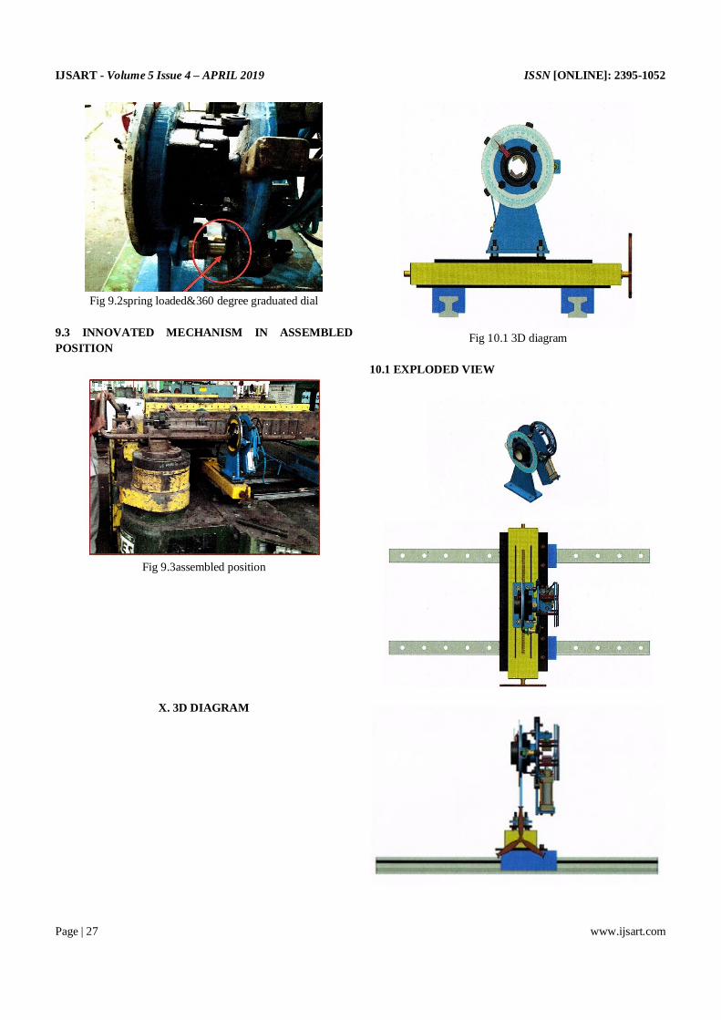
Fig 10.1 3D diagram
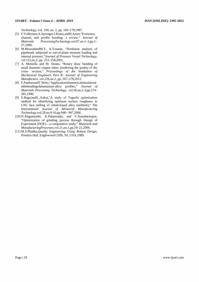
10.1 EXPLODED VIEW

IJSART - Volume 5 Issue 4 – APRIL 2019 ISSN [ONLINE]: 2395-1052
Page | 28 www.ijsart.com
Fig 10.2 exploded view
Table10.1 probable resistance & remedial action
XI. COMPARISION
11.1 IMPROVEMENTS IN BENDING MACHINE
Table 11.1IMPROVEMENTS IN BENDING MACHINE
XII. RESULT
Due to the development of the new system for the
twist angle bend by implementing the house development fixtures for holding the tube while doing twist bend. Thecycle time has reduced by 61.27%. Due toreduce in the cycle time has increased the productivity in the unit.
The system developed for twist bend has reduced the
rework and remarking on the tube so that work on the tube done properly without any damage.
REFERENCES
[1] F.Stachowicz, “Bending with up setting of copper tube elbows,” Journal of Materials Processing Technology, vol.100, no.1, pp. 236–240,2000.
[2] L.G.Brazier,“On the flexure of thin cylindrical shells and other ‘Thin’ sections,” Proceedings of the Royal Society of London A, vol. 116, pp. 104–114,1927.
[3] P. K. Shaw and S. Kyriakides, “Inelastic analysis of thin-walled tubesundercyclicbending,”InternationalJournalofSolidsandStructures,vol.21,no.11,pp.1073–1100,1985.
[4] S.Kyriakidesand P.K.Shaw, “Inelastic buckling of tubes under cyclic bending,” Journal of Pressure Vessel
IJSART - Volume 5 Issue 4 – APRIL 2019 ISSN [ONLINE]: 2395-1052
Page | 29 www.ijsart.com
Technology, vol. 109, no. 2, pp. 169–178,1987. [5] F.Vollertsen,A.Sprenger,J.Kraus,andH.Arnet,“Extrusion,
channel, and profile bending: a review,” Journal of Materials ProcessingTechnology,vol.87,no.1–3,pp.1–27,1999.
[6] M.MouradandM.Y. A.Younan, “Nonlinear analysis of pipebends subjected to out-of-plane moment loading and internal pressure,”Journal of Pressure Vessel Technology, vol.123,no.2, pp. 253–258,2001.
[7] A. Mentella and M. Strano, “Rotary draw bending of small diameter copper tubes: predicting the quality of the cross- section,” Proceedings of the Institution of Mechanical Engineers Part B: Journal of Engineering Manufacture, vol.226,no.2, pp. 267–278,2012.
[8] F.PaulsenandT.Welo,“Applicationofnumericalsimulationinthebendingofaluminium-alloy profiles,” Journal of Materials Processing Technology, vol.58,no.2-3,pp.274–285,1996.
[9] E.BagciandS¸.Aykut,“A study of Taguchi optimization method for identifying optimum surface roughness in CNC face milling of cobalt-based alloy (stellite6),” The International Journal of Advanced Manufacturing Technology,vol.29,no.9-10,pp.940– 947,2006.
[10] N.Alagumurthi, K.Palaniradja, and V.Soundararajan, “Optimization of grinding process through Design of Experiment (DOE)—a comparative study,” Materials and ManufacturingProcesses,vol.21,no.1,pp.19–21,2006.
[11] M.S.Phadke,Quality Engineering Using Robust Design, Prentice Hall, Englewood Cliffs, NJ, USA,1989.