Embed Size (px)
Citation preview

BT 200 04/00 English
(S)J31069-D0075-U001-A2-6318 Page 1
BT 200Physical Bus Test Devicefor PROFIBUS-DP
Table of Contents1 DESCRIPTION .............................................. 2
2 COMMISSIONING ........................................ 4
3 NORMAL MODE ........................................... 53.1 WIRING TEST........................................................ 63.2 ERROR MESSAGES OF THE WIRING TEST ................ 7
4 SPECIALIST MODE ................................... 104.1 OPERATOR CONTROL.......................................... 104.2 STATION (RS 485) TEST..................................... 124.3 BRANCH TEST .................................................... 134.4 DISTANCE .......................................................... 154.5 REFLECTION TEST .............................................. 164.6 SERVICE ............................................................ 17
5 LOG MODE ................................................. 18
6 SAMPLE APPLICATIONS ......................... 20
7 MAINTENANCE AND TROUBLE-SHOOTING .................................................... 247.1 CHARGING STATUS OF THE BATTERY.................... 247.2 CHANGING THE BATTERY..................................... 247.3 SELF-TESTS....................................................... 257.4 ERROR CORRECTION TABLE ................................ 26
8 ACCESSORIES AND REPLACEMENTPARTS ........................................................... 27
9 TECHNICAL DATA ..................................... 28

English 04/00 BT 200
(S)J31069-D0075-U001-A2-6318Page 2
1 Description
Purpose of the BT 200The BT 200 offers diagnostics for PROFIBUS-DP systems without having to use additionalmeasuring aids (e.g., PC or oscilloscope).
BT 200 - version 2Version 2 of the BT 200 offers additionalfunctions.• Log function• 6-language user interface• Test of the PROFIBUS-DP master inter-
face• Indication of the master's address• Wiring test with stations connected• New, reasonably-priced compact char-
ging device

BT 200 04/00 English
(S)J31069-D0075-U001-A2-6318 Page 3
Operator control elements and display
Fig. 1 BT 200 operator control elements and display
1) PROFIBUS-DP connection (9-pin sub D)2) LC display (2 x 16 characters)3) ON/OFF button4) Charging socket for plug connec-
tor/charging device5) TEST key (start test)6) CURSOR keys7) OK key (various functions)8) ESCAPE key (terminate)9) Charging contacts for charging device

English 04/00 BT 200
(S)J31069-D0075-U001-A2-6318Page 4
2 CommissioningBefore initial commissioning, check your deli-very, and charge the battery.
Scope of deliveryThe delivery includes:- 1 BT 200- 1 battery- 1 test plug connector (wiring test)- 1 test cable, length: 2 m (station test)- 1 user's guide
Charging the battery- Open the battery compartment (see
chapter on changing the battery), andcheck to determine whether the battery isinstalled. Install the battery if necessary.
- Charge battery of the BT 200 via char-ging shell (approx. 4 hours).
ΥΥΥΥ Attention!The battery is always delivered uncharged.The charging shell is not included and mustbe ordered separately.
- Measuring cannot be performed duringthe charging procedure.

BT 200 04/00 English
(S)J31069-D0075-U001-A2-6318 Page 5
3 Normal Mode
The BT 200 is turned on with the ON/OFFbutton.Keep the ON/OFF button pressed until yousee a reaction on the display.
Standby displayThe following display appears for approx. 2seconds after the device is turned on.
Battery displayThe battery capacity display is then shown forapprox. 2 seconds.
Operational displayAfter the battery display disappears, the BT200 assumes normal mode and displays thestart screen for the wiring test.
Only the wiring test can be performed in nor-mal mode.When the BT 200 is in log mode (the cursorlooks different), an extra screen appears aftereach test.
Energy saver modeIf no keys are pressed for approx. 3 minutesand no measurements are being performed,the BT 200 goes off automatically.
English 04/00 BT 200
(S)J31069-D0075-U001-A2-6318Page 6
3.1 Wiring Test
Principle of measuringThe wiring test for a bus segment is perfor-med between the BT 200 and the test plugconnector. During the installation phase, atest can be performed from connector to con-nector. See figure 2. The test connector isalways installed on the one end of the bussegment.Short circuits can also be determined outsidethe test path. The bus segment may only beequipped with a terminating resistor at thebeginning and at the end.
Fig. 2 Step-by-step measuring principle
Performing the testThe test can be performed with or withoutstations connected.The test is started by pressing the TEST key.One of the following two messages is dis-played if the test was concluded successfully.
For one terminating resistor (as long as in-stallation has not been completed, only oneterminal resistor is present)
After installation has been concluded, two re-sistors must be inserted.The test is concluded by pressing the OK key,and a new wiring test can be started.The wiring test can also be concluded or ter-minated at any time by pressing the ESC key.

BT 200 04/00 English
(S)J31069-D0075-U001-A2-6318 Page 7
3.2 Error Messages of the Wiring Test
Station test
Check to determine whether the power supplyhas been turned off for all stations and powercomponents.
Wire mix-up
Exchange the cores in the corresponding plugconnector.
Υ The wiring test must be performed eachtime a new PROFIBUS plug connector isconnected. Otherwise an even numberof wire mix-ups will not be recognized.
Short circuit
Locate and correct the short circuit.A frequent cause (e.g., of shield short circuits)is the incorrect application of shield braiding inthe plug connectors.

English 04/00 BT 200
(S)J31069-D0075-U001-A2-6318Page 8
Line or shield break
Possible error causes:• Interruption of several cores• Interruption of cores and shield• Test plug connector not connected
To obtain a correct measuring result for shieldbreak, the shield may not be connected withground.
With all four messages, first check the plugconnectors/connections in question. If theseare okay, replace the line.

BT 200 04/00 English
(S)J31069-D0075-U001-A2-6318 Page 9
None or more than two terminating resistors
Page with the "→→→→""←←←←" keys.
Place a terminating resistor at the beginningand end of the bus segment.
Page with the "→→→→""←←←←" keys.
Remove or deactivate all terminating resistorsexcept the two at the beginning and end ofthe bus segment.

English 04/00 BT 200
(S)J31069-D0075-U001-A2-6318Page 10
4 Specialist ModeYou can switch from normal mode to specia-list mode by pressing ESC and OK at the sa-me time.The following functions are available in spe-cialist mode.
- Wiring test. See normal mode.- Station test (RS 485 test)- Branch test- Distance measurement- Reflection test- Service menu
4.1 Operator ControlThe BT 200 is menu-controlled via the inputkeys of the sealed keyboard (figure 1).
CursorThe current cursor position in the display isshown as a flashing arrow and indicates thefunction which is being performed.
If the BT200 is in log mode, the cursor positi-on is shown with a modified arrow.

BT 200 04/00 English
(S)J31069-D0075-U001-A2-6318 Page 11
Menu itemsMenu items are selected with the cursor andactivated with the OK key. The ESC key canbe used to terminate a running function or tojump back to the higher-level menu item.
Menu structureSTART
Battery test
N mode
Wiring
(Normal mode)
s comde (Specalist mode)
Wiring
RS485
Branch
Distance
Reflection
SERVICE
Language
Settings
Baud rate
Resistance
Log mode
Communication
Battery
Contrast
Calibration
FW version
Self test
(Test)
(Measurement)
(Test)
(Test)
(Test)
(Test)
(Settings)
Deleting
Fig. 3 Menu structure

English 04/00 BT 200
(S)J31069-D0075-U001-A2-6318Page 12
4.2 Station (RS 485) TestThis test is used to test the RS 485 interfaceof a single slave or master.
Performing the testDisconnect bus connector from the station.Establish point-to-point connection betweenstation and BT 200. See figure 4.
Υ Only the included test cable may be used forthis connection.
Fig. 4 Point-to-point connection
Turn on the station since the test must beperformed with an active station. The mastermust be in "RUN" mode.Start station test.Set address of the station to be tested asshown below.
Test resultsPossible test results are listed below.- RS 485 okay (slave okay)- RS 485 defective. (No continuous signal
receipt; repeat test.)- No response (nothing at all received)- 5 V : (corresponding measured value)- RTS signal (YES or NO)
station

BT 200 04/00 English
(S)J31069-D0075-U001-A2-6318 Page 13
4.3 Branch TestThis can be used to check the availability ofall slaves on PROFIBUS or to address an in-dividual slave.The branch test can also be performed be-yond repeaters/LWL.
Performing the testDisconnect all masters from the bus (e.g., PG,OP and CP). See figure 5.Caution: The bus termination must remainensured.Connect BT 200 to the bus.Set the baud rate configured on the bus onthe BT 200.Set the desired address for individual slavetest.Set address to "000" for the total test.
Confirm with OK the address (slave or ma-ster) which was detected by the BT 200.
Fig. 5 Measuring principle of the branch test

English 04/00 BT 200
(S)J31069-D0075-U001-A2-6318Page 14
Test resultsDuring the total branch test, each availableslave is indicated in a list of available stations(i.e., LIFE LIST).
- LIFE LIST
For an individual test
- No response (e.g., no station with thisbus address on the bus.)
- Faulty station (e.g., a slave number hasbeen assigned twice.)

BT 200 04/00 English
(S)J31069-D0075-U001-A2-6318 Page 15
4.4 DistanceDistance measurement can only detect lineslonger than 15 m. No distance measurementcan be performed when repeaters are used.
Performing the testTurn off the power supply of all bus stations.Connect test plug connector to one end of theline and the BT 200 to the other end. (Turnoff resistor for BT 200.)Start distance measurement.After the start, the BT 200 requests three va-lues which must be entered on the keyboard.- Loop resistance (default = 110 Ω/km)
The default value can be changed viamenu item Service.
- Number of 12-Mbaud plug connec-tors/devices with longitudinal inductivity
- Resistance value per connector/device(default = 0.32 Ω)
After entry of the last value and confirmationwith OK, measurement is performed.
Measurement resultsThe following appears on the display.
The following error messages can occur du-ring measurement.- No resistor inserted.- Display "0 m" (no plausible length deter-
mined)- More than 1 resistor inserted.
Possible causes of errors:- Distance < 15 m- Stub lines, located on the measuring path
Correct the error, and repeat the measure-ment.

English 04/00 BT 200
(S)J31069-D0075-U001-A2-6318Page 16
4.5 Reflection TestThe reflection test can be used to determine afaulty location (e.g., short circuit) or to confirmthe distance measurement (not via repeater).
Reflections can occur, for example, in the fol-lowing situations:- Stub lines exist.- Too many terminating resistors have be-
en inserted, or none have been inserted.- Change to a wrong type of cable occurs
within the measuring path.
Performing the testDisconnect master from the bus, and makesure that:- the bus termination has power- no bus communication occurs- no test plug connector is connected.Connect BT 200 to one end of the line.Start reflection measurement.
Test resultsIf no reflection (i.e., fault) is detected, the fol-lowing message appears.
If a reflection is detected, the following mes-sage appears.
The number in the display specifies the di-stance in meters from the measuring point tothe faulty point.If the distance of the reflection measurementcorresponds to a previous distance measu-rement, this distance measurement is confir-med. The wiring of the bus segment whichwas measured is correct.

BT 200 04/00 English
(S)J31069-D0075-U001-A2-6318 Page 17
4.6 Service
SettingsThe following settings can be changed in theService menu.- Language (German/English/French/- Italian/Spanish/Portuguese)- Loop resistance (50 to 200 Ω/km)- Baud rate (9600 baud to 12 Mbaud)- Contrast (↑↓ )- Log mode (on/off)
CommunicationActivate the interface for data transmission forthe log function.
DisplaysThe Service menu gives you the following in-formation.- Firmware version- Battery capacity
Hardware testThis tests the internal hardware.
CalibrationCalibration is not necessary when the stan-dard type-A PROFIBUS cable is used.The accuracy of distance and reflection mea-surement is achieved by calibration with 2 testcables of different known lengths.
Fig. 6 Principle of calibration

English 04/00 BT 200
(S)J31069-D0075-U001-A2-6318Page 18
5 Log ModeIn log mode, performed tests are stored onthe BT 200. Later this information can betransferred over a serial interface to a PC withlog SW.Log mode can be enabled and disabled in theSERVICE menu.Log mode remains set even when the BT 200is turned off. This mode remains on until thesetting in the SERVICE menu is changedagain.An identifier (X0 ..X999) is assigned to eachtest to be stored on the BT 200.The following table shows the maximumnumber of tests which can be stored and theiridentifiers.
Type of Test ID Letter Max. NumberWiring test V 128Station test T 128Branch test S 10Distance meas. E 10Reflection test R 10
Storing the testsAfter each test, the following prompt with thenext available identifier appears on the dis-play.
The identifier can be changed with the cursoror accepted with OK.If you manually enter an identifier which hasalready been assigned, it will be overwritten.

BT 200 04/00 English
(S)J31069-D0075-U001-A2-6318 Page 19
Memory fullThis display appears when the maximumnumber of tests to be stored is reached.
After you confirm with OK, the last selectedidentifier appears which you can thenoverwrite.
This identifier cannot be changed. The lasttest result is overwritten.
Transferring tests to a PCThe test data are stored in non-volatile me-mory (i.e., they can be transferred to the PCeven after the BT 200 is turned off).Before starting the transmission to the PC,connect the included "log" cable to a COMinterface of the PC and to the 9-pin sub Dsocket of the BT 200.The transmission is activated with theSERVICE menu and indicated on the dis-play.
Communication can be terminated with theESC key. The following display appears.
OK terminates communication.ESC terminates "termination" of communi-cation.
Deleting the test dataThe test data can be deleted with theSERIVCE menu.
English 04/00 BT 200
(S)J31069-D0075-U001-A2-6318Page 20
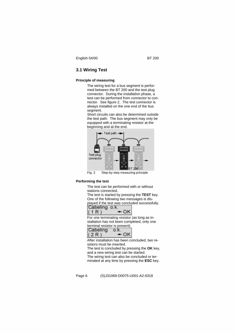
6 Sample Applications
Testing the complete PROFIBUS-DP• No master may be connected to the bus.• The "life list" can also be generated with a re-
peater and optical paths.• Parts of the system can be tested in advance
without the master for their bus functionality.
Fig. 7 Sample test 1

BT 200 04/00 English
(S)J31069-D0075-U001-A2-6318 Page 21
Wiring test for connected stations• Stations no longer need to be removed from the
bus.(Stations must be powered down!)(Measurement not possible over repeater)
Fig. 8 Sample test 2

English 04/00 BT 200
(S)J31069-D0075-U001-A2-6318Page 22
Wiring test of a segment via PG socket on therepeater
Fig. 9 Sample test 3

BT 200 04/00 English
(S)J31069-D0075-U001-A2-6318 Page 23
Wiring test of a segment behind a repeater andwith terminator
Fig. 10 Sample test 4
English 04/00 BT 200
(S)J31069-D0075-U001-A2-6318Page 24
7 Maintenance and Trouble-Shooting
7.1 Charging Status of the BatteryThe charging status of the battery is indicatedfor approximately 2 seconds during startup.This display then disappears.The charging status can also be indicated viathe service menu during operation. If the battery goes dead during operation, thecharging status begins to flash.
Standard values If you want to reset all values to their statuson delivery, keep both cursor keys pressedfor approx. three seconds after switch-on.
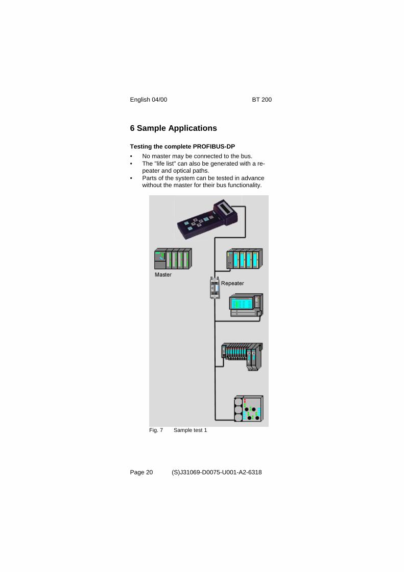
7.2 Changing the Battery
Fig. 11 Changing the battery

BT 200 04/00 English
(S)J31069-D0075-U001-A2-6318 Page 25
7.3 Self-Tests
The BT 200 performs self-tests automaticallyand on request (hardware test).
- Internal RS 485 driver test
The test is performed each time the stati-on and branch test is called.
- RAM test A cyclic RAM test is performed.
- Flash EPROM test A cyclic EPROM test is performed.
- RS 485 driver test
The individual tests (e.g., RAM test, flashEPROM test and display key test) can also beselected in specialist mode via service menu -HW test.
If an error is detected during the self-test, youmust proceed as shown in the error correc-tion table.
English 04/00 BT 200
(S)J31069-D0075-U001-A2-6318Page 26
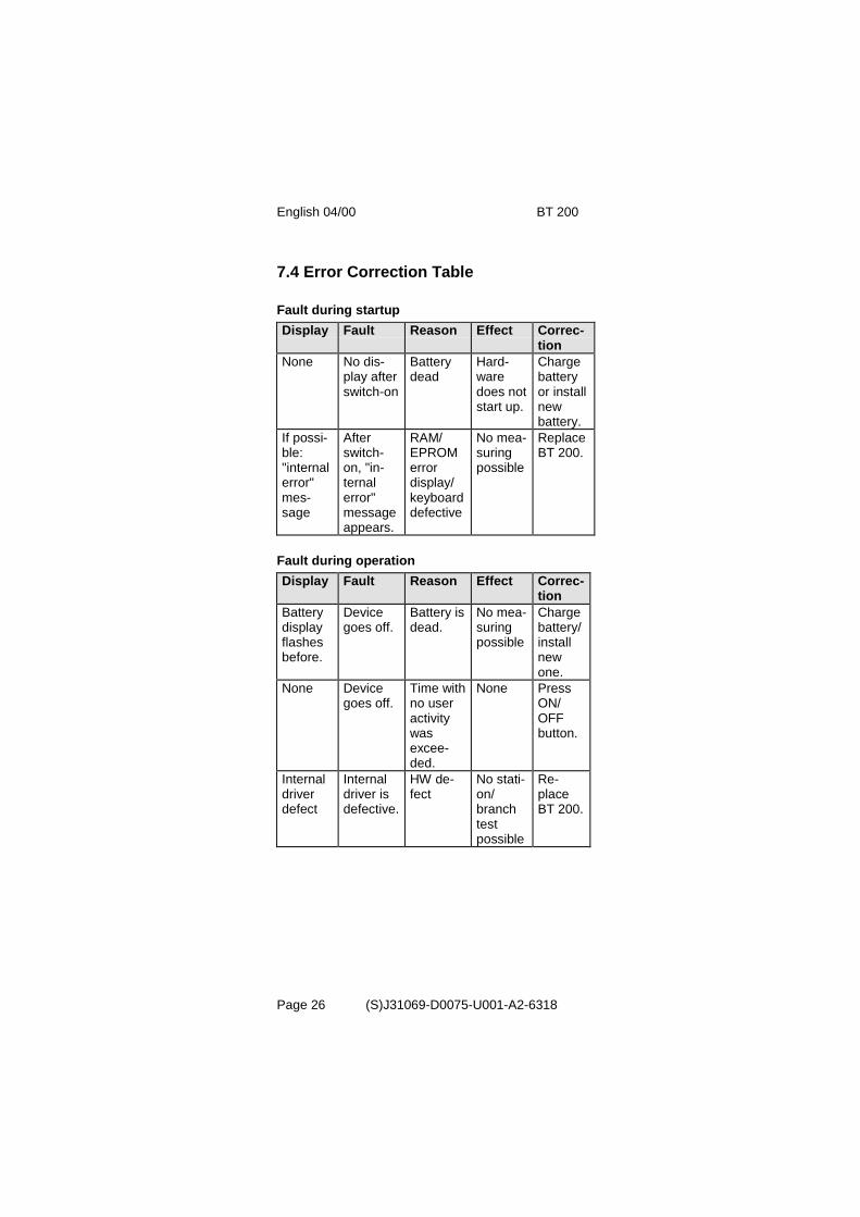
7.4 Error Correction Table
Fault during startupDisplay Fault Reason Effect Correc-
tionNone No dis-
play afterswitch-on
Batterydead
Hard-waredoes notstart up.
Chargebatteryor installnewbattery.
If possi-ble:"internalerror"mes-sage
Afterswitch-on, "in-ternalerror"messageappears.
RAM/EPROMerrordisplay/keyboarddefective
No mea-suringpossible
ReplaceBT 200.
Fault during operationDisplay Fault Reason Effect Correc-
tionBatterydisplayflashesbefore.
Devicegoes off.
Battery isdead.
No mea-suringpossible
Chargebattery/installnewone.
None Devicegoes off.
Time withno useractivitywasexcee-ded.
None PressON/OFFbutton.
Internaldriverdefect
Internaldriver isdefective.
HW de-fect
No stati-on/branchtestpossible
Re-placeBT 200.

BT 200 04/00 English
(S)J31069-D0075-U001-A2-6318 Page 27
8 Accessories and ReplacementParts
The following components can be ordered undertheir MLFB number.
Designation/Picture MLFB NumberTest connector
6EP8106-0AC20
Log kitfor Win95/98/NT4• CD-ROM in
Ger/Eng/French• Cable
6ES7193-8MA00-0AA0
Plug-in charger w. powerpack for: 230 V AC
110 V AC6ES7193-8LA00-0AA06ES7193-8LB00-0AA0
Battery with connectioncable
6EP8106-HA01
Test-cable station test9-pin sub D on9-pin sub D (1 to 1)
6EP8106-OHC01

English 04/00 BT 200
(S)J31069-D0075-U001-A2-6318Page 28
9 Technical Data
GeneralDimensions 210 * 100 * 55 mmWeight 400 gBattery capacity ≥ 720 mAhLife ≥ 8 hVoltage supply NiCd, 4.8 V batteryDisplay LCD, 2 * 16 charac-
tersBaud rate 9600 Bd to 12 MBdProtection class IP 20Measuring accuracy Length measurement
(+/-3m)
Environmental RequirementsOperating temperature + 5°C to +45°CStorage temperature -20°C to +60°CRelative humidity Maximal 95% / 24°C
Middle 75% / 17°C(withoutcondensation)
Air pressureoperationstorage
795 to 1080 hPa660 to 1080 hPa
EMC guidelinesCE labeling DIN EN 61326-1:
1998EN 50 081-1EN 50 082-2
Physical RequirementsVibration during operation IEC 1131-2Shock stress during operation IEC 1131-2Free fall IEC 1131-2/68-2-32
CertificationsULCSAOrder number 6ES7 181-0AA01-
0AA0

BT 200 04/00 English
(S)J31069-D0075-U001-A2-6318 Page 29
AbbreviationsBd Baud (1 Bd = 1 character (bit/second)
BT Physical bus test device
CP Communications processor
EMC Electromagnetic compatibility
MBd 1 MBd = 106 baud
NiCd Nickel cadmium
NN Miles above sea level
OP Operator panel
PG Programmer
RTS Request to send
Info Info Info Info Info Info Info
This document can be downloaded free of chargefrom the Internet under the following URL:
http://www.ad.siemens.de/simatic-cs
Continuous current information on SIMATIC productsis available on the Internet under:
http://www.ad.siemens.de/simatic
SIMATIC Customer Support can be reached under:
Tel. +49 (911) 895 7000Fax. +49 (911) 895 7002

English 04/00 BT 200
(S)J31069-D0075-U001-A2-6318Page 30

BT 200 04/00 Les français
(S)J31069-D0075-U001-A2-6318 Page 1