Embed Size (px)
Citation preview
NASA/CR-2000-210109
Description of the AILS Alerting Algorithm
Paul Samanant and Mike Jackson
Honeywell, Inc., Minneapolis, Minnesota
May 2000
https://ntrs.nasa.gov/search.jsp?R=20000040456 2018-05-20T13:07:27+00:00Z

The NASA STI Program Office... in Profile
Since its founding, NASA has been dedicated
to the advancement of aeronautics and spacescience. The NASA Scientific and Technical
Information (STI) Program Office plays a key
part in helping NASA maintain this
important role.
The NASA STI Program Office is operated by
Langley Research Center, the lead center forNASA's scientific and technical information.
The NASA STI Program Office provides
access to the NASA STI Database, the
largest collection of aeronautical and space
science STI in the world. The Program Officeis also NASA's institutional mechanism for
disseminating the results of its research and
development activities. These results are
published by NASA in the NASA STI Report
Series, which includes the following report
types:
• TECHNICAL PUBLICATION. Reports of
completed research or a major significant
phase of research that present the results
of NASA programs and include extensive
data or theoretical analysis. Includes
compilations of significant scientific andtechnical data and information deemed
to be of continuing reference value. NASA
counterpart of peer-reviewed formal
professional papers, but having less
stringent limitations on manuscript
length and extent of graphic
presentations.
• TECHNICAL MEMORANDUM.
Scientific and technical findings that are
preliminary or of specialized interest,
e.g., quick release reports, working
papers, and bibliographies that containminimal annotation. Does not contain
extensive analysis.
• CONTRACTOR REPORT. Scientific and
technical findings by NASA-sponsored
contractors and grantees.
CONFERENCE PUBLICATION.
Collected papers from scientific and
technical conferences, symposia,
seminars, or other meetings sponsored or
co-sponsored by NASA.
SPECIAL PUBLICATION. Scientific,
technical, or historical information from
NASA programs, projects, and missions,
often concerned with subjects having
substantial public interest.
TECHNICAL TRANSLATION. English-
language translations of foreign scientific
and technical material pertinent toNASA's mission.
Specialized services that complement the
STI Program Office's diverse offerings include
creating custom thesauri, building customized
databases, organizing and publishing
research results.., even providing videos.
For more information about the NASA STI
Program Office, see the following:
• Access the NASA STI Program Home
Page at httpY/www.sti.nasa.gov
• Email your question via the Internet to
• Fax your question to the NASA STI
Help Desk at (301) 621-0134
• Telephone the NASA STI Help Desk at(301) 621-0390
Write to:
NASA STI Help Desk
NASA Center for AeroSpace Information7121 Standard Drive
Hanover, MD 21076-1320
NASA/CR-2000-210109
Description of the AILS Alerting Algorithm
Paul Samanant and Mike Jackson
Honeywell, Inc., Minneapolis, Minnesota
National Aeronautics and
Space Administration
Langley Research Center
Hampton, Virginia 23681-2199
Prepared for Langley Research Centerunder Purchase Order L-10690
May 2000

Available from:
NASA Center for AeroSpace Information (CASI)7121 Standard Drive
Hanover, MD 21076-1320
(301) 621-0390
National Technical Information Service (NTIS)
5285 Port Royal Road
Springfield, VA 22161-2171(703) 605-6000
Table of Contents
LIST OF FIGURES ................................................................................................................................................. V
LIST OF TABLES .................................................................................................................................................. VII
1 INTRODUCTION AND OVERVIEW .......................................................................................................... 1
1.1 INTRODUCTION ........................................................................................................................................... 1
1.2 CHANGES TO THE AILS ALGORITHM ........................................................................................................ 1
1.3 DOCUMENT OVERVIEW (HOW TO USE THIS DOCUMENT) ..................................................................... 2
2 AILS ALGORITHM OVERVIEW ................................................................................................................ 4
2.1 GENERAL ALGORITHM DESCRIPTION ....................................................................................................... 4
2.2 ELLIPTICAL PROTECTION ZONE ................................................................................................................ 6
2.3 AILS FAN ...................................................................................................................................................... 6
2.4 AILS FORWARD PROJECTION ASSUMPTIONS ........................................................................................... 6
2.5 SNAPPING VS. ACTUAL STATES ................................................................................................................. 7
2.6 ON APPROACH/OFF APPROACH CRITERIA FOR SNAP DETERMINATION ............................................... 7
2.7 ON APPROACH/OFF APPROACH INTRUDER AND EVADER TRACK ......................................................... 8
2.8 ELLIPSE SIZE ADJUSTMENTS IF AIRCRAFT IS OFF APPROACH ............................................................... 8
2.9 PROTECTION ELLIPSE FRAME OF REFERENCE ......................................................................................... 9
2.10 PROTECTED ESCAPE ZONE (CURRENTLY DISABLED) ...................................................................... 10
2.11 AILS TURN TIME (CURRENTLY DISABLED) ...................................................................................... 12
2.12 TRACK RATE DEADBAND .................................................................................................................... 13
3 AILS COORDINATE FRAME DEFINITIONS ......................................................................................... 14
3.1 TRANSFORMATION FROM EARTH TO LOCAL COORDINATES .............................................................. 14
3.2 DEFINITION OF INTERNAL AILS COORDINATE SYSTEM ...................................................................... 14
3.3 SIDE AND DOWNRANGE VIEWS OF AILS INTERNAL COORDINATE SYSTEM ..................................... 16
3.4 TRANSFORMATION EQUATIONS BETWEEN PARALLEL RUNWAY COORDINATES ............................. 18
3.5 USE OF APPROACH DATA TO PERFORM CONVERSION TO AILS COORDINATES ................................ 19
4 AILS TOP LEVEL DESCRIPTION WITH FLOW CHARTS ................................................................ 22
4.1 AILS TOP LEVEL DESCRIPTION ............................................................................................................... 22
4.2 AILS ALGORITHM STRUCTURE AND FLOW CHARTS ............................................................................. 22
4.2.1 Larcalertjull Flowchart ................................................................................................................... 24
4.2.2 Scenario Setup (ilook blocks) Flowchart .......................................................................................... 25
4.2.3 Chkvertjull Flowchart ..................................................................................................................... 26
4.2.4 Chktrack_ull Flowchart ................................................................................................................... 27
4.2.5 Chktrackjull Subdiagram Flowchart ............................................................................................... 28
4.2.6 Chkrange_ull Flowchart .................................................................................................................. 29
5 AILS DATA AND PSEUDO CODE DESCRIPTIONS .............................................................................. 30
5.1 LARCALERT FULL AND TOP LEVEL AILS DESCRIPTIONS .................................................................... 30
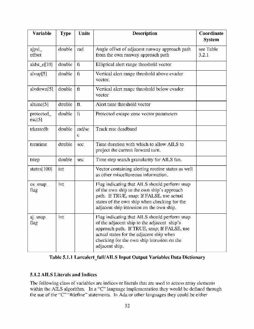
5.1.1 Larcalertjull/AILS Input�Output Parameters Description .............................................................. 30
5.1.2 AILSLiteralsandIndices.................................................................................................................. 32
5.1.3 AILS Array Element Descriptions ..................................................................................................... 33
5.1.4 Larcalertjull Local Internal Variables Data Dictionary ................................................................ 36
5.1.5 Larcalertjull (AILS Executive) Algorithm Pseudo Code ................................................................. 39
5.2 SUBUNIT CHKVERT FULL DESCRIPTION ................................................................................................ 46
5.2.1 Subunit Chlo_ertjull Input Parameters ............................................................................................. 46
5.2.2 Subunit Chlo_ertjull Output Parameters .......................................................................................... 47
5.2.3 Subunit Chlo, ertjull Local Variables ............................................................................................... 47
5.2.4 Subunit Chlo_ertjull Algorithm Pseudo Code .................................................................................. 47
5.3 SUBUNIT CHKRANGE_FULL DESCRIPTION ............................................................................................. 48
5.3.1 Subunit Chkrangejull Input Parameters ......................................................................................... 49
5.3.2 Subunit Chkrangejull Output Parameters ....................................................................................... 50
5.3.3 Subunit Chkrangejull Local Variables ............................................................................................ 50
5.3.4 Subunit Chkrangejull Pseudocode .................................................................................................. 51
5.4 SUBUNIT CHKTRACK FULL DESCRIPTION ............................................................................................. 51
5.4.1 Subunit Chktrackjull Input Parameters ........................................................................................... 51
5.4.2 Subunit Chktrackjull Output Parameters ........................................................................................ 53
5.4.3 Subunit Chktrackjull Local Variables ............................................................................................. 53
5.4.4 Subunit Chktrack Full Algorithm Pseudocode ................................................................................. 54
6 AILS PRE-CALL AND POST CALL REQUIREMENTS AND RECOMMENDATIONS ................... 57
6.1 OVERVIEW AND FLOWCHART FOR AILS PRE AND POST-PROCESSING ............................................... 57
6.2 CALLING RATE FOR AILS ......................................................................................................................... 57
6.3 CONVERSION TO AILS COORDINATES ................................................................................................... 59
6.4 TRACK AND TRACK RATE DERIVATION ................................................................................................. 59
6.5 TRACK RATE FILTER ................................................................................................................................. 60
6.6 DATA INTEGRITY TEST ............................................................................................................................ 61
6.7 EXTRAPOLATE AND TIME ALIGN DATA ................................................................................................. 61
6.8 COMPUTE RANGE, RANGE RATE, AND BEARING TO THE POTENTIAL AILS AIRCRAFF ................... 62
6.9 DETERMINE AILS AIRCRAFF PAIRING .................................................................................................... 62
6.9.1 Range Pairs Test Code ...................................................................................................................... 63
6.10 ON-APPROACH/OFF APPROACH DETERMINATION ........................................................................... 65
6.11 ELLIPSE AND TIME PARAMETER ADJUSTMENTS .............................................................................. 65
6.12 DATA REQUIREMENTS SUMMARY AND DEFAULT VALUES ............................................................ 65
6.12.1 AILS Parameter Input Summary Table ............................................................................................. 65
6.12.2 Default AILS Alerting Parameter Values .......................................................................................... 66
6.12.3 Default AILS Algorithm Parameters ................................................................................................. 67
6.12.4 Default Protected Escape Zone Parameters ..................................................................................... 67
6.13 STATUS ARRAY INTERPRETATION ..................................................................................................... 67
6.14 STATIC VS DYNAMIC MEMORY ALLOCATION REQUIREMENTS FOR AILS .................................... 68
7 AILS EQUATIONS ....................................................................................................................................... 69
7.1 TURN RADIUS ............................................................................................................................................ 69
7.2 INSIDE A ROTATED ELLIPSE .................................................................................................................... 69
7.3 INSIDE ELLIPSE FOR FUTURE TRACK ..................................................................................................... 70
7.4 AILS FAN EQUATIONS .............................................................................................................................. 71
ii
8 APPENDIX A. ACRONYMS AND ABBREVIATIONS .......................................................................... 73
9 APPENDIX B. GLOSSARY ......................................................................................................................... 74
10 APPENDIX C. REFERENCES .................................................................................................................... 75
iii

iv
List of Figures
Figure
Figure
Figure
Figure
Figure
Figure
Figure
Figure
Figure
Figure
Figure
Figure
Figure
Figure
Figure
Figure
Figure
Figure
Figure
2.1.1 AILS Fan and Intrusion Check Scenarios .............................................................................................. 5
2.9.1 Ellipse Slaving To Aircraft Frame vs Applvach Frame ...................................................................... 10
2.10.1 Protected Escape Zones ..................................................................................................................... 12
3.1.1 Transformation From Spherical Earth To Local Runway Coordinates ............................................... 14
3.2.1 AILS Runway Coordinate System ......................................................................................................... 15
3.3.1 Side View Of Ails Coordinate System ................................................................................................... 17
3.3.2 Downrange View Of Local AILS Coordinates ...................................................................................... 17
3.5.1 Key Approach Parameters ................................................................................................................... 20
4.2.1 Larcalert ffull Flow Chart .................................................................................................................... 24
4.2.2 Scenario Setup (ilook blocks) Flowchart ............................................................................................. 25
4.2.3 Chkvert ffull Flowchart ........................................................................................................................ 26
4.2.4 Chktrack ffull Flowchart ...................................................................................................................... 27
4.2.5 Subdiagram Chktrack ffull flow chart .................................................................................................. 28
4.2.6 Chkrangejull flow chart ...................................................................................................................... 29
6.2.1 Relevant Pre and Post Processing For Larcalertjull ......................................................................... 58
6.3.1 Com, ersion to AILS Coordinates .......................................................................................................... 59
6.5.1 Track Rate Filter. ................................................................................................................................. 60
7.2.1 Rotated Ellipse Coordinates ................................................................................................................ 69
7.4.1 Calculation of Position on Turn Arc .................................................................................................... 72
V

vi
List of Tables
Table 1.3.1 Document Reference Table ...................................................................................................................... 3
Table 2.1.1 AILS Alert Level Attributes ...................................................................................................................... 4
Table 2.1.2 Current AILS Alerting Parameters .......................................................................................................... 6
Table 2.8.1 On Applvach/Off Applvach Ellipse and Alert Determinations ............................................................... 9
Table 2.10.1 Protected Escape Zone Parameter Definition ..................................................................................... 11
Table 3.2.1 Definition Of AILS Runway Frame Position Variables ......................................................................... 16
Table 3.4.1 State Variable Transformations With NO Snap ..................................................................................... 18
Table 3.4.2 State Variable Transformations With Snap ........................................................................................... 18
Table 3.5.1 Definition Of Key AILS Applvach Related Parameters ........................................................................ 21
Table 4.2.1 AILS Major Functional Blocks and Routines ........................................................................................ 23
Table 5.1.1 Larcalertjull/AILS Input Output Variables Data Dictiona1:y .............................................................. 32
Table 5.1.2 AILS Indices and Literals Specifcations ................................................................................................ 33
Table 5.1.3 AILS Array Element Descriptions .......................................................................................................... 36
Table 5.1.4 AILS Local Variable Data Dictionary ................................................................................................... 39
Table 5.2.1 Subunit Chkvertjull Input Parameters ................................................................................................. 46
Table 5.2.2 Subunit Chkvertjull Output Parameters ............................................................................................... 47
Table 5.2.3 Subunit Chkvertjull Local Variables .................................................................................................... 47
Table 5.3.1 Subunit Chkrange Full Input Parameters ............................................................................................. 50
Table 5.3.2 Subunit Chkrange Full Output Parameters .......................................................................................... 50
Table 5.3.3 Subunit Chkrangejull Local Variables ................................................................................................. 50
Table 5.4.1 Subunit Chktrackjull Input Parameters ............................................................................................... 53
Table 5.4.2 Subunit Chktrackjull Output Parameters ............................................................................................. 53
Table 5.4.3 Subunit Chktrackjull Local Variables .................................................................................................. 53
Table 6.4.1 Equations For Track Rate Derivation ................................................................................................... 60
Table 6.9.1 Range Pairs Test Parameters ................................................................................................................. 63
Table 6.12.1 AILS Parameter Input Summary .......................................................................................................... 66
vii

Vlll
1 Introduction and Overview
1.1 Introduction
This document is a complete description of the Airborne Information for Lateral Spacing
(AILS) alerting algorithms. The documentation corresponds to the most current version of
AILS used in simulation at NASA Langley Research Center (LaRC) and in test flights with
NASA (B757 Aries) and Honeywell (Gulfstream IV) in CY99. The original AILS which has
been documented in Reference [3], had two versions of the algorithm: - "Full AILS" and
"Parameter AILS." The full version was intended for in-flight use, while the parameter version
was for lab testing only. This document only describes the current version of the full AILS
algorithm - the parameter AILS algorithm was not carried forward to match the full version.
Modifications to the original AILS were the result of simulation and analysis work performed at
Honeywell Technology Center and at NASA Langley Research Center. The analysis at
Honeywell focused on an assessment of the relative safety of the system by simulating many
scenarios. This analysis uncovered some weaknesses of the original algorithm related to the
circular shape of the protected region. The NASA simulation activities in the B757 Integrated
Flight Deck (IFD), part of the Research Simulation Integrated Laboratory (RSIL), focused on the
human factors aspects of the system design. These simulations helped tune the system
parameters for pilot acceptance. Both analyses performed suggested possible modifications to
the algorithms, and NASA and Honeywell engineers collaborated to agree on the changes to the
algorithms.
Additional changes to the AILS algorithms were required as the focus shifted from simulation
and analysis towards a real-world real-time implementation, such as dealing with non-parallel
runways, offset thresholds, and non-zero runway latitude, longitude and altitude.
The equations and logic to implement the algorithm changes were designed and implemented at
Honeywell Technology Center, with some assistance from Bill Capron (a Lockheed contractor at
NASA LaRC).
Section 1.2 below presents a detailed list of the changes that were made to the AILS algorithm.
The latest version of AILS, which contains these changes, was coded in PASCAL and tested in
simulations and flight experiments in 1999. (There is also an equivalent "C" version of the
code that was used by Honeywell Technology Center to perform simulation and analysis work.)
This document provides a Software Design Document-like description of this most current
AILS software.
1.2 Changes to the AILS Algorithm
Following is a list of the major changes made to the AILS algorithm.
Added vertical dimension to alerting. This required the addition of a vertical situation
determination routine. It also mandated changing from the existing point-of-closest-
approach formulations in favor of the solution of a quadratic equation to obtain entry and
exit times into the horizontal alert region.
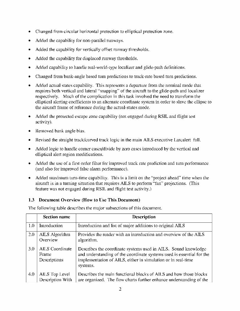
• Changedfrom circularhorizontalprotectionto elliptical protectionzone.
• Addedthecapabilityfor non-parallelrunways.
• Addedthecapabilityfor vertically offsetrunwaythresholds.
• Added the capability for displaced runway thresholds.
• Added capability to handle real-world-type localizer and glide-path definitions.
• Changed from bank-angle based turn predictions to track-rate based turn predictions.
• Added actual states capability. This represents a departure from the nominal mode that
requires both vertical and lateral "snapping" of the aircraft to the glide-path and localizer
respectively. Much of the complication in this task involved the need to transform the
elliptical alerting coefficients to an alternate coordinate system in order to slave the ellipse to
the aircraft frame of reference during the actual-states mode.
• Added the protected escape zone capability (not engaged during RSIL and flight test
activity).
• Removed bank angle bias.
• Revised the straight track/curved track logic in the main AILS executive Larcalert_full.
• Added logic to handle comer cases/divide by zero cases introduced by the vertical and
elliptical alert region modifications.
• Added the use of a first order filter for improved track rate prediction and turn performance
(and also for improved false alarm performance).
• Added maximum turn-time capability. This is a limit on the "project ahead" time when the
aircraft is in a turning situation that requires AILS to perform "fan" projections. (This
feature was not engaged during RSIL and flight test activity.)
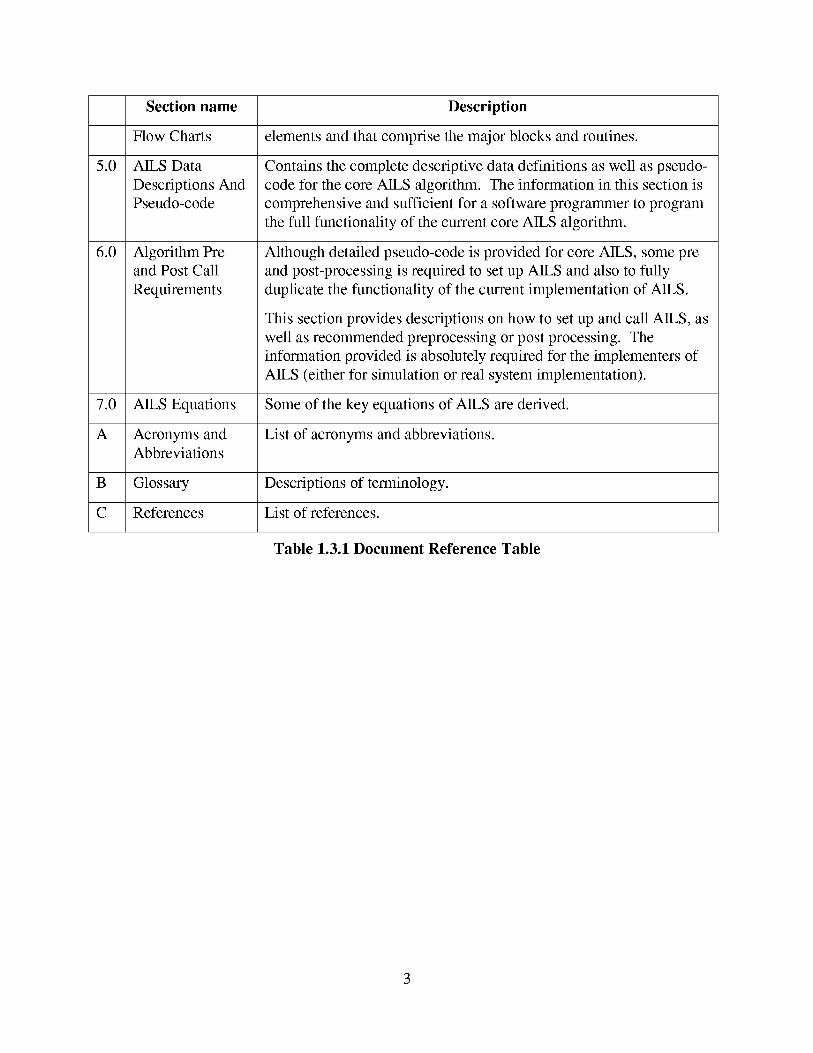
1.3 Document Overview (How to Use This Document)
The following table describes the major subsections of this document.
3.0
4.0
Section name Description
Introduction Introduction and list of major additions to original AILS
AILS Algorithm Provides the reader with an introduction and overview of the AILS
Overview algorithm.
AILS Coordinate
Frame
Descriptions
AILS Top Level
Description With
Describes the coordinate systems used in AILS. Sound knowledge
and understanding of the coordinate systems used is essential for the
implementation of AILS, either in simulation or in real-time
systems.
Describes the main functional blocks of AILS and how those blocks
are organized. The flow charts further enhance understanding of the
5.0
6.0
7.0
A
B
C
Sectionname Description
Flow Charts elements and that comprise the major blocks and routines.
AILS Data
Descriptions And
Pseudo-code
Algorithm Preand Post Call
Requirements
Contains the complete descriptive data definitions as well as pseudo-
code for the core AILS algorithm. The information in this section is
comprehensive and sufficient for a software programmer to program
the full functionality of the current core AILS algorithm.
Although detailed pseudo-code is provided for core AILS, some pre
and post-processing is required to set up AILS and also to fully
duplicate the functionality of the current implementation of AILS.
This section provides descriptions on how to set up and call AILS, as
well as recommended preprocessing or post processing. The
information provided is absolutely required for the implementers of
AILS (either for simulation or real system implementation).
AILS Equations Some of the key equations of AILS are derived.
Acronyms and List of acronyms and abbreviations.Abbreviations
Glossary Descriptions of terminology.
References List of references.
Table 1.3.1 Document Reference Table
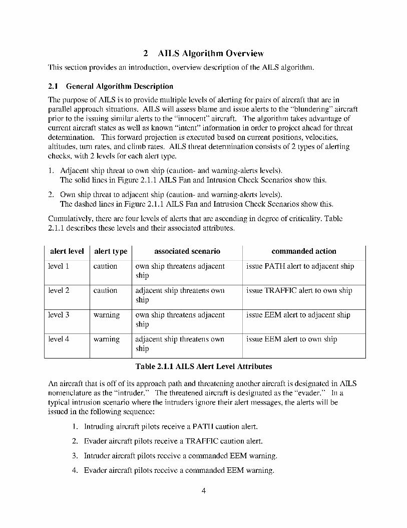
2 AILS Algorithm Overview
This section provides an introduction, overview description of the AILS algorithm.
2.1 General Algorithm Description
The purpose of AILS is to provide multiple levels of alerting for pairs of aircraft that are in
parallel approach situations. AILS will assess blame and issue alerts to the "blundering" aircraft
prior to the issuing similar alerts to the "innocent" aircraft. The algorithm takes advantage of
current aircraft states as well as known "intent" information in order to project ahead for threat
determination. This forward projection is executed based on current positions, velocities,
altitudes, turn rates, and climb rates. AILS threat determination consists of 2 types of alerting
checks, with 2 levels for each alert type.
.
.
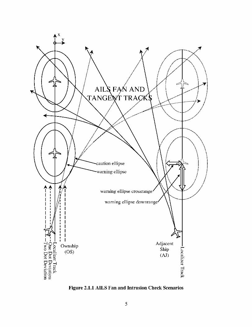
Adjacent ship threat to own ship (caution- and warning-alerts levels).
The solid lines in Figure 2.1.1 AILS Fan and Intrusion Check Scenarios show this.
Own ship threat to adjacent ship (caution- and warning-alerts levels).
The dashed lines in Figure 2.1.1 AILS Fan and Intrusion Check Scenarios show this.
Cumulatively, there are four levels of alerts that are ascending in degree of criticality. Table
2.1.1 describes these levels and their associated attributes.
alert level alert type associated scenario commanded action
level 1 caution own ship threatens adjacent issue PATH alert to adjacent ship
ship
level 2 caution adjacent ship threatens own issue TRAFFIC alert to own ship
ship
level 3 warning own ship threatens adjacent issue EEM alert to adjacent ship
ship
level 4 warning adjacent ship threatens own issue EEM alert to own ship
ship
Table 2.1.1 AILS Alert Level Attributes
An aircraft that is off of its approach path and threatening another aircraft is designated in AILS
nomenclature as the "intruder." The threatened aircraft is designated as the "evader." In a
typical intrusion scenario where the intruders ignore their alert messages, the alerts will be
issued in the following sequence:
1. Intruding aircraft pilots receive a PATH caution alert.
2. Evader aircraft pilots receive a TRAFFIC caution alert.
3. Intruder aircraft pilots receive a commanded EEM warning.
4. Evader aircraft pilots receive a commanded EEM warning.
4
- AIL FAN AND
:-: ,,
- /
/ellipse
g ellipse
: I ...,l/i warning ellipse crossranI ."E!l_!:
warning ellipse downran:
Ownship
(os)
/ iiiiiiil;; .$" _ :. -
V ,.-::--ii--:-::,i......-ii -
.............-._ /- :
•.. / ...-\ --,.......... /
"o.. ...o..."
.,..-
/" ...
....-
°.
.-" i.,-" i
- /
/°°°."
Adjacent
Ship
(A J)_,,a.N
Figure 2.1.1 AILS Fan and Intrusion Check Scenarios
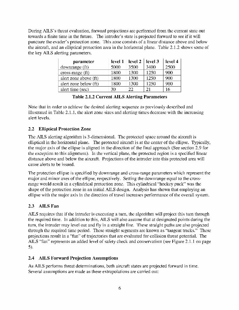
During AILS's threat evaluation, forward projections are performed from the current state out
towards a finite time in the future. The intruder's state is projected forward to see if it will
puncture the evader's protection zone. This zone consists of a linear distance above and below
the aircraft, and an elliptical protection area in the horizontal plane. Table 2.1.2 shows some of
the key AILS alerting parameters.
parameter
downrange (ft)
cross-range (ft)
alert zone above (ft)
level 1
5000
level 2
3500
level 3
3400
level 4
2500
1800 1300 1250 900
1800 1300 1250 900
alert zone below(ft) 1800 1300 1250 900
alert time(sec) 30 22 21 16
Table 2.1.2 Current AILS Alerting Parameters
Note that in order to achieve the desired alerting sequence as previously described and
illustrated in Table 2.1.1, the alert zone sizes and alerting times decrease with the increasingalert levels.
2.2 Elliptical Protection Zone
The AILS alerting algorithm is 3-dimensional. The protected space around the aircraft is
elliptical in the horizontal plane. The protected aircraft is at the center of the ellipse. Typically,
the major axis of the ellipse is aligned in the direction of the final approach (See section 2.9 for
the exception to this alignment). In the vertical plane, the protected region is a specified linear
distance above and below the aircraft. Projections of the intruder into this protected area will
cause alerts to be issued.
The protection ellipse is specified by downrange and cross-range parameters which represent the
major and minor axes of the ellipse, respectively. Setting the downrange equal to the cross-
range would result in a cylindrical protection zone. This cylindrical "hockey puck" was the
shape of the protection zone in an initial AILS design. Analysis has shown that employing an
ellipse with the major axis in the direction of travel increases performance of the overall system.
2.3 AILS Fan
AILS requires that if the intruder is executing a turn, the algorithm will project this turn through
the required time. In addition to this, AILS will also assume that at designated points during the
turn, the intruder may level out and fly in a straight line. These straight paths are also projected
through the required time period. These straight segments are known as "tangent tracks." These
projections result in a "fan" of trajectories that are evaluated for collision threat potential. The
AILS "fan" represents an added level of safety check and conservatism (see Figure 2.1.1 on page
5).
2.4 AILS Forward Projection Assumptions
As AILS performs threat determinations, both aircraft states are projected forward in time.
Several assumptions are made as these extrapolations are carried out:
Both aircraftareassumedto fly with aconstantgroundspeed.
Unlessactualstatesmodeis in effect,theevaderis assumedto beinitialized on thelocalizerbeamandto stayon thelocalizerbeamfor thedurationof thecurrentpredictiontimes.
Theintruderis assumedto be flying a constantradiusturn atthecurrentturn rateandcanlevelout atany timeandfly straightalonga tracktangentto theturn arc. Thecurrentconfigurationis setcomputeturn ratebasedon trackratethat hasbeenderivedfrom GPSvelocities,but it canalsobeconfiguredto usebankangle.
TheAILS forward searchtime step:(deltatAILS) is an input andis currentlysetto thevalueof 0.5 seconds.This time stepwill determinethesearchresolutionwhenAILS is performingtheintruderandevaderprojectionsin it's processof threatdetermination.
ThetangenttracksarecomputedeveryN time steps,whereN is chosendynamicallysuchthatthetangenttracksaretakenbetweenevery1.5to 3.0degrees.(Thecomputationof thetangenttrackfrequencyassumesthat thetime stepis 0.5 seconds,or a fractionof that. Itshouldstill work if thetime stepis different,but it maynot producetracksbetween1.5and3.0degrees
2.5 Snapping vs. Actual States
The AILS algorithm works on designated pairs of aircraft. For a particular set of aircraft, in
each respective aircraft's computer, two scenarios are considered:
.
.
Where the own ship is considered as the intruder and the adjacent ship is considered as the
evader;
Where the own ship is considered as the evader and the adjacent ship is considered as theintruder.
In each scenario, the intruder's current state information is used to project the intruder's
anticipated position as a function of time. The evader's actual current states are used with the
exception of cross-range and altitude. Instead, in accordance with the "intended states"
philosophy, the evader's assumed position for cross-range and altitude are "snapped" to the
localizer and glide slope, respectively. This protects the region on the intended path where the
aircraft is most likely to be in the future.
If the aircraft is NOT established on its approach, its actual states will be used regardless of
whether the scenario requires it to be intruder or evader. The reason for the "snapping" is the
design philosophy which makes use of the known intended approach path of an aircraft.
2.6 On Approach/Off Approach Criteria For Snap Determination
If an aircraft is substantially off of it's approach, it is not appropriate to "snap" that aircraft to
the approach path. "Snapping" under this condition would significantly misrepresent the
position of the aircraft, which could lead to either false alarms or missed alerts. Following is the
criteria used to determine if an aircraft is significantly off of its approach:
Aircraft declared NOT to be on approach if:
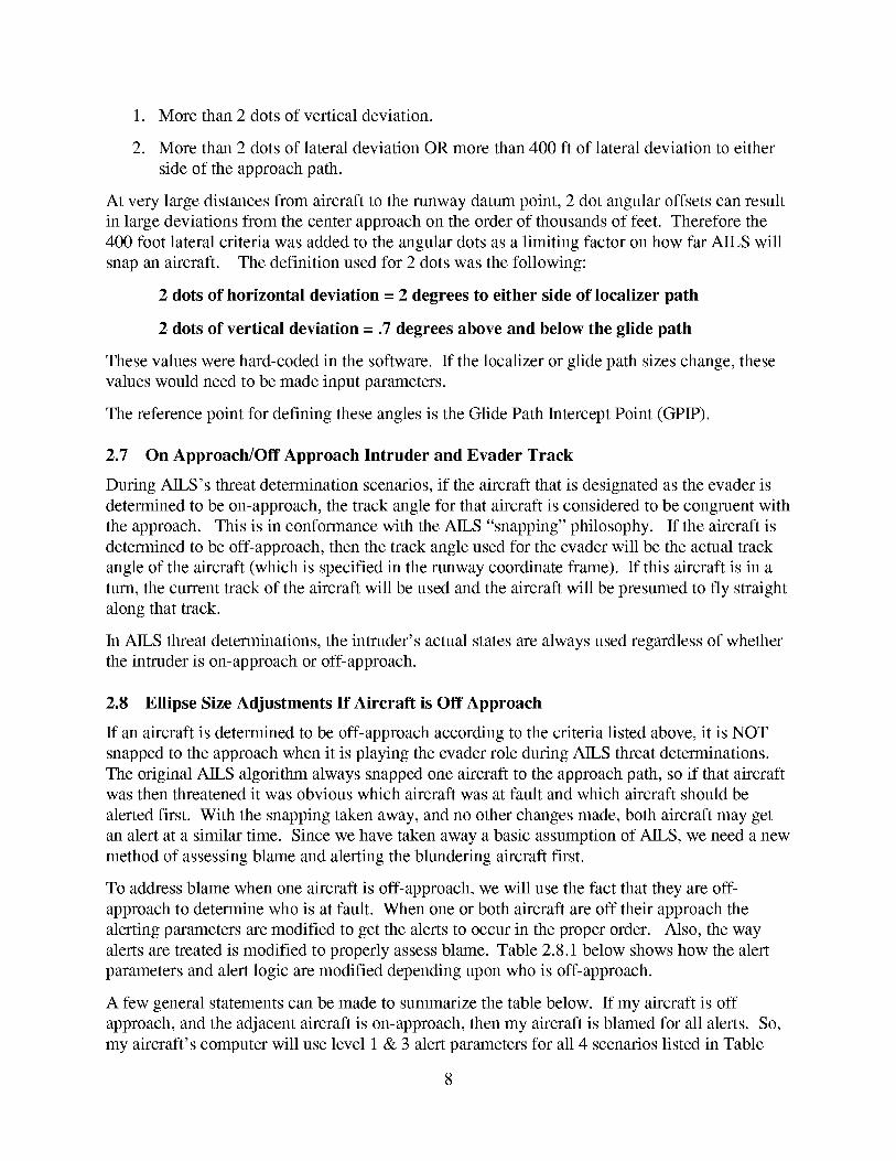
1. More than2 dotsof vertical deviation.
2. More than2 dotsof lateraldeviationOR morethan400ft of lateraldeviationto eithersideof theapproachpath.
At very largedistancesfrom aircraft to therunwaydatumpoint, 2 dot angularoffsetscanresultin largedeviationsfrom thecenterapproachon theorderof thousandsof feet. Thereforethe400foot lateralcriteriawasaddedto theangulardotsasalimiting factor onhow far AILS willsnapanaircraft. Thedefinition usedfor 2 dotswasthefollowing:
2 dots of horizontal deviation = 2 degrees to either side of localizer path
2 dots of vertical deviation = .7 degrees above and below the glide path
These values were hard-coded in the software. If the localizer or glide path sizes change, these
values would need to be made input parameters.
The reference point for defining these angles is the Glide Path Intercept Point (GPIP).
2.7 On Approach/Off Approach Intruder and Evader Track
During AILS's threat determination scenarios, if the aircraft that is designated as the evader is
determined to be on-approach, the track angle for that aircraft is considered to be congruent with
the approach. This is in conformance with the AILS "snapping" philosophy. If the aircraft is
determined to be off-approach, then the track angle used for the evader will be the actual track
angle of the aircraft (which is specified in the runway coordinate frame). If this aircraft is in a
turn, the current track of the aircraft will be used and the aircraft will be presumed to fly straight
along that track.
In AILS threat determinations, the intruder's actual states are always used regardless of whether
the intruder is on-approach or off-approach.
2.8 Ellipse Size Adjustments If Aircraft is Off Approach
If an aircraft is determined to be off-approach according to the criteria listed above, it is NOT
snapped to the approach when it is playing the evader role during AILS threat determinations.
The original AILS algorithm always snapped one aircraft to the approach path, so if that aircraftwas then threatened it was obvious which aircraft was at fault and which aircraft should be
alerted first. With the snapping taken away, and no other changes made, both aircraft may get
an alert at a similar time. Since we have taken away a basic assumption of AILS, we need a new
method of assessing blame and alerting the blundering aircraft first.
To address blame when one aircraft is off-approach, we will use the fact that they are off-
approach to determine who is at fault. When one or both aircraft are off their approach the
alerting parameters are modified to get the alerts to occur in the proper order. Also, the way
alerts are treated is modified to properly assess blame. Table 2.8.1 below shows how the alert
parameters and alert logic are modified depending upon who is off-approach.
A few general statements can be made to summarize the table below. If my aircraft is off
approach, and the adjacent aircraft is on-approach, then my aircraft is blamed for all alerts. So,
my aircraft's computer will use level 1 & 3 alert parameters for all 4 scenarios listed in Table
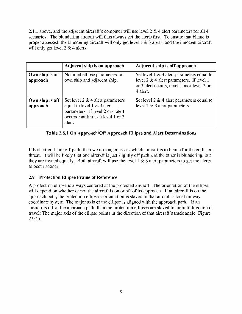
2.1.1above,andtheadjacentaircraft's computerwill uselevel2 & 4 alertparametersfor all 4scenarios.Theblunderingaircraftwill thusalwaysgetthealertsfirst. To ensurethatblameisproperassessed,theblunderingaircraftwill only get level1 & 3 alerts,andtheinnocentaircraftwill onlyget level2 & 4 alerts.
Own ship is on
approach
Own ship is off
approach
Adjacent ship is on approach Adjacent ship is off approach
Nominal ellipse parameters for
own ship and adjacent ship.
Set level 2 & 4 alert parameters
equal to level 1 & 3 alert
parameters. If level 2 or 4 alert
occurs, mark it as a level 1 or 3
alert.
Set level 1 & 3 alert parameters equal to
level 2 & 4 alert parameters. If level 1
or 3 alert occurs, mark it as a level 2 or
4 alert.
Set level 2 & 4 alert parameters equal to
level 1 & 3 alert parameters.
Table 2.8.1 On Approach/Off Approach Ellipse and Alert Determinations
If both aircraft are off-path, then we no longer assess which aircraft is to blame for the collision
threat. It will be likely that one aircraft is just slightly off path and the other is blundering, but
they are treated equally. Both aircraft will use the level 1 & 3 alert parameters to get the alertsto occur sooner.
2.9 Protection Ellipse Frame of Reference
A protection ellipse is always centered at the protected aircraft. The orientation of the ellipse
will depend on whether or not the aircraft is on or off of its approach. If an aircraft is on the
approach path, the protection ellipse's orientation is slaved to that aircraft's local runway
coordinate system: The major axis of the ellipse is aligned with the approach path. If an
aircraft is off of the approach path, than the protection ellipses are slaved to aircraft direction of
travel: The major axis of the ellipse points in the direction of that aircraft's track angle (Figure
2.9.1).
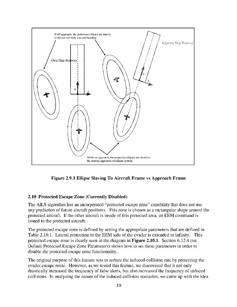
If off approach, die protection ellipses are slavedto the ah'crafl body axis and heading.
Ship Ru_ lwayi
Adjacent Ship Runway
X
I
I
I
I
While on approach, the protection ellipses are slaved to
the runway approach coordinate system.
Figure 2.9.1 Ellipse Slaving To Aircraft Frame vs Approach Frame
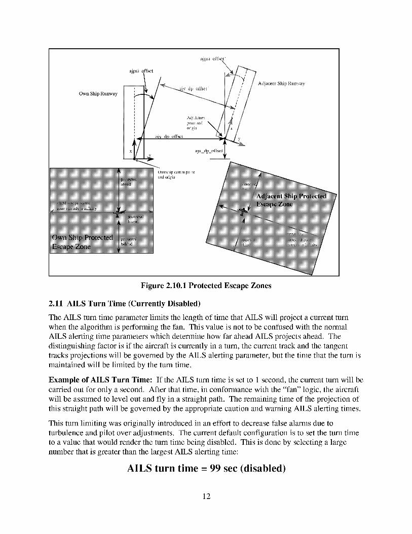
2.10 Protected Escape Zone (Currently Disabled)
The AILS algorithm has an incorporated "protected escape zone" capability that does not use
any prediction of future aircraft positions. This zone is chosen as a rectangular shape around the
protected aircraft. If the other aircraft is inside of this protected area, an EEM command is
issued to the protected aircraft.
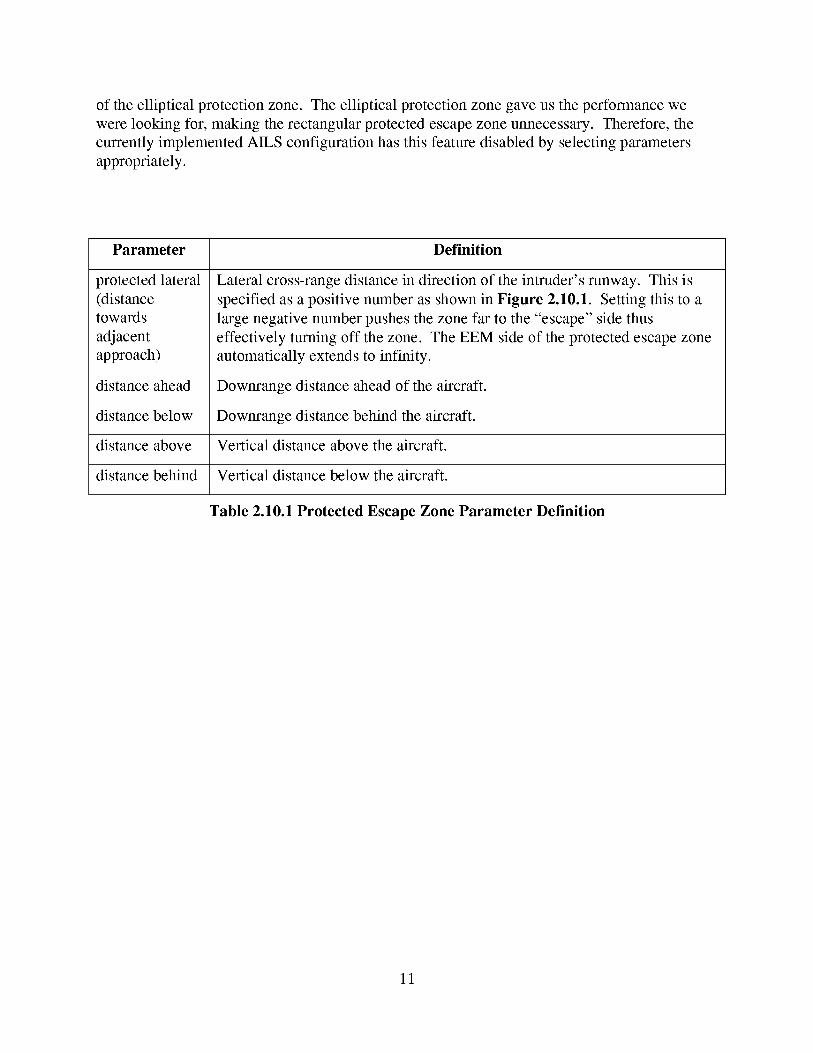
The protected escape zone is defined by setting the appropriate parameters that are defined in
Table 2.10.1. Lateral protection to the EEM side of the evader is extended to infinity. This
protected escape zone is clearly seen in the diagram in Figure 2.10.1. Section 6.12.4 (on
Default Protected Escape Zone Parameters) shows how to set these parameters in order to
disable the protected escape zone functionality.
The original purpose of this feature was to reduce the induced-collision rate by protecting the
evader escape route. However, as we tested this feature, we discovered that it not only
drastically increased the frequency of false alerts, but also increased the frequency of induced
collisions. In analyzing the nature of the induced collision scenarios, we came up with the idea
10
of theelliptical protectionzone. Theelliptical protectionzonegaveustheperformancewewerelooking for, makingtherectangularprotectedescapezoneunnecessary.Therefore,thecurrentlyimplementedAILS configurationhasthis featuredisabledby selectingparametersappropriately.
Parameter Definition
protectedlateral(distancetowardsadjacentapproach)
Lateralcross-rangedistancein directionof the intruder'srunway. This isspecifiedasapositivenumberasshownin Figure 2.10.1. Settingthis to alargenegativenumberpushesthezonefar to the"escape"sidethuseffectively turningoff thezone. TheEEM sideof theprotectedescapezoneautomaticallyextendsto infinity.
distanceahead Downrange distance ahead of the aircraft.
distance below Downrange distance behind the aircraft.
distance above Vertical distance above the aircraft.
distance behind Vertical distance below the aircraft.
Table 2.10.1 Protected Escape Zone Parameter Definition
11
Own Ship Runway
y dl? ofi]_ei'
offset
x
Ownship datum point
_iiiiiiiiiiiiii and origin
Adjacent Ship Rv, nway
iiiiiii_Nt_.,t_
iiiiiii_A_N._iiiiiiiiii
}_t_iiiiiiiiiiiiiiiiiiiiiii
Figure 2.10.1 Protected Escape Zones
2.11 AILS Turn Time (Currently Disabled)
The AILS turn time parameter limits the length of time that AILS will project a current turn
when the algorithm is performing the fan. This value is not to be confused with the normal
AILS alerting time parameters which determine how far ahead AILS projects ahead. The
distinguishing factor is if the aircraft is currently in a turn, the current track and the tangent
tracks projections will be governed by the AILS alerting parameter, but the time that the turn is
maintained will be limited by the turn time.
Example of AILS Turn Time: If the AILS turn time is set to 1 second, the current turn will be
carried out for only a second. After that time, in conformance with the "fan" logic, the aircraft
will be assumed to level out and fly in a straight path. The remaining time of the projection of
this straight path will be governed by the appropriate caution and warning AILS alerting times.
This turn limiting was originally introduced in an effort to decrease false alarms due to
turbulence and pilot over adjustments. The current default configuration is to set the turn time
to a value that would render the turn time being disabled. This is done by selecting a large
number that is greater than the largest AILS alerting time:
AILS turn time = 99 sec (disabled)
12
2.12 Track Rate Deadband
A dead band is applied to aircraft track rates that are close to zero. The purpose for this is to
prevent unnecessary turns and fans resulting from minor track rate perturbations and
turbulence. If an aircraft's track rate is at or below this value, a zero value is selected as the
aircraft track rate. The following value of the track rate dead band reflects the value used in the
most current configuration.
AILS track rate deadband = .00024 rad/sec
13
3 AILS Coordinate Frame Definitions
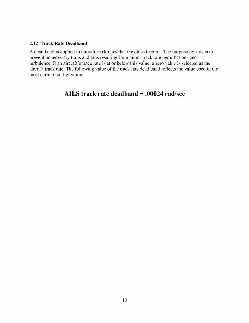
3.1 Transformation From Earth To Local Coordinates
AILS uses two coordinate systems - one aligned with the own ship's intended approach, and one
aligned with the adjacent ship's intended approach. The coordinate system origins are located at
the approach datum points (typically the runway thresholds), and the x-axes are aligned with the
approach centerlines (typically the runway centerlines). Standard navigation data for each AILS
aircraft is converted to these local coordinate systems (Figure 3.1.1).
Coordinate transformation is from geodetic lat, Ion, and msl alt to local runway which is
specified in terms of the datum point.
"T-_-[latitude, longitude, msl altitude][osx, osy, osh]
(z axis is not referenced)
own ship danm_ point
ould be nmway thi'eshold)
rotation
Figure 3.1.1 Transformation From Spherical Earth To Local Runway Coordinates
Note that the "z" axis points down but the altitude or "h" axis points up and is positive up. This
is the main axis of vertical reference in the AILS algorithms.
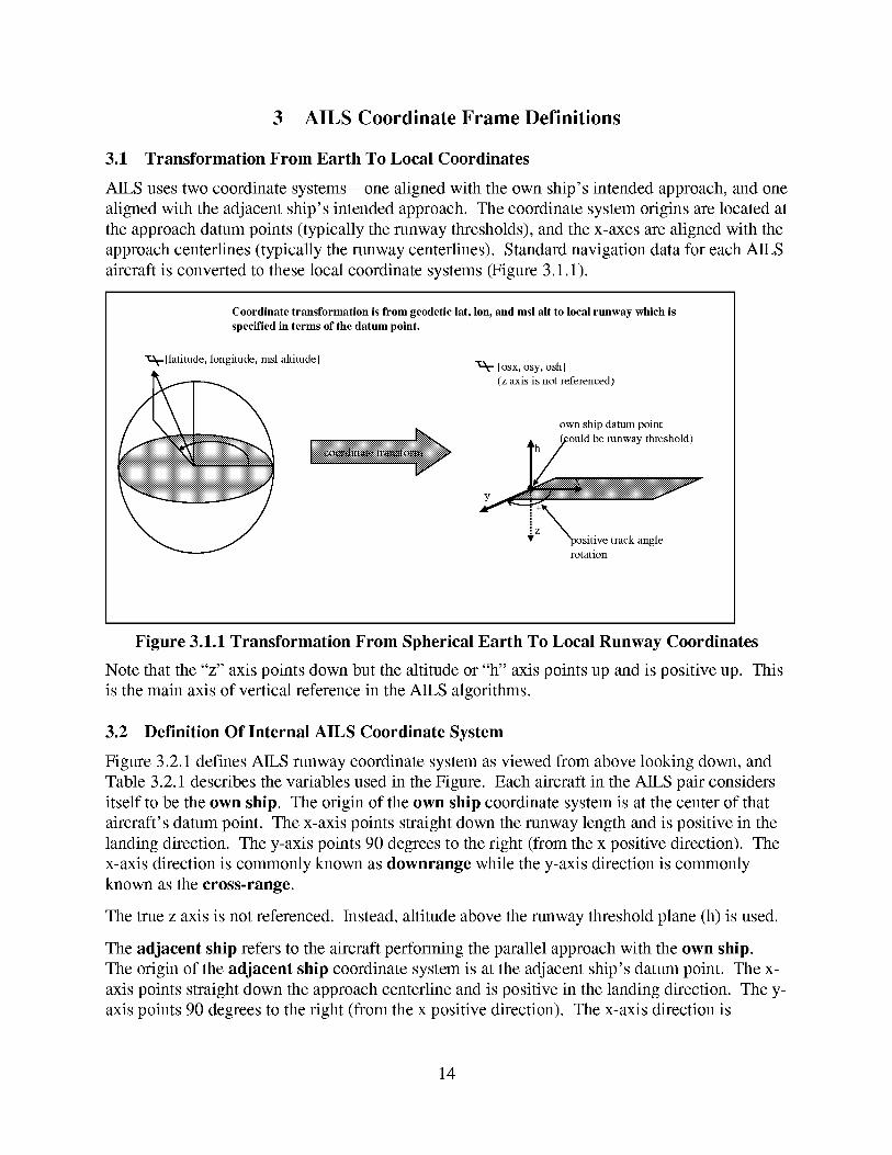
3.2 Definition Of Internal AILS Coordinate System
Figure 3.2.1 defines AILS runway coordinate system as viewed from above looking down, and
Table 3.2.1 describes the variables used in the Figure. Each aircraft in the AILS pair considers
itself to be the own ship. The origin of the own ship coordinate system is at the center of that
aircraft's datum point. The x-axis points straight down the runway length and is positive in the
landing direction. The y-axis points 90 degrees to the right (from the x positive direction). The
x-axis direction is commonly known as downrange while the y-axis direction is commonly
known as the cross-range.
The true z axis is not referenced. Instead, altitude above the runway threshold plane (h) is used.
The adjacent ship refers to the aircraft performing the parallel approach with the own ship.
The origin of the adjacent ship coordinate system is at the adjacent ship's datum point. The x-
axis points straight down the approach centerline and is positive in the landing direction. The y-
axis points 90 degrees to the right (from the x positive direction). The x-axis direction is
14
commonlyknownasdownrangewhile they-axisdirectionis commonlyknownasthe cross-
range.
As AILS performs it's intrusion checks it will designate one aircraft as an intruder and the other
aircraft as the evader. During these checks, both aircraft have to placed in a single frame of
reference. AILS chooses the intruder frame of reference to contain the intruder and evader
positions.
Top view looking down
ajpsi_offset
(positive shown)
Own Ship Runway
ajpsi___offset_egafive shown)
Adjacen"; Ship Rup_.way
offset'
osxpos
x
aj y_dp_offset
adjacent ship
datum point
own ship
datum point
ajx_dp_oft_et
)os
offset'
jypos
Figure 3.2.1 AILS Runway Coordinate System
variable description
osxpos downrange position of own ship relative to own ship coordinate system
osypos cross-range position of own ship relative to own ship coordinate system
oshpos h position of own ship relative to own ship coordinate system
ajxpos downrange position of adjacent ship relative to adjacent ship coordinate
system
15
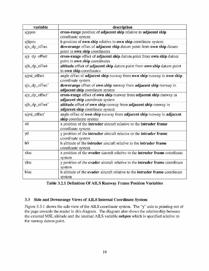
variable description
ajypos cross-range position of adjacent ship relative to adjacent ship
coordinate system
ajhpos h position of own ship relative to own ship coordinate system
ajx_dp_offset downrange offset of adjacent ship datum point from own ship datum
point in own ship coordinates
ajy_dp_offset cross-range offset of adjacent ship datum point from own ship datum
point in own ship coordinates
ajh_dp_offset
ajpsi_offset
ajx_dp_offset'
altitude offset of adjacent ship datum point from own ship datum point
in own ship coordinates
ajpsi_offset'
x0
angle offset of adjacent ship runway from own ship runway in own ship
coordinate system
downrange offset of own ship runway from adjacent ship runway in
adjacent ship coordinate system
ajy_dp_offset' cross-range offset of own ship runway from adjacent ship runway in
adjacent ship coordinate system
ajh_dp_offset' altitude offset of own ship runway from adjacent ship runway in
adjacent ship coordinate system
angle offset of own ship runway from adjacent ship runway in adjacent
ship coordinate system
yO
hO
xloc
yloc
hloc
x position of the intruder aircraft relative to the intruder flame
coordinate system
y position of the intruder aircraft relative to the intruder flame
coordinate systemh altitude of the intruder aircraft relative to the intruder flame
coordinate system
x position of the evader aircraft relative to the intruder flame coordinate
system
y position of the evader aircraft relative to the intruder flame coordinate
systemh altitude of the evader aircraft relative to the intruder flame coordinate
system
Table 3.2.1 Definition Of AILS Runway Frame Position Variables
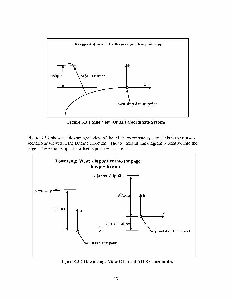
3.3 Side and Downrange Views of AILS Internal Coordinate System
Figure 3.3.1 shows the side view of the AILS coordinate system. The "y" axis is pointing out of
the page towards the reader in this diagram. The diagram also shows the relationship between
the external MSL altitude and the internal AILS variable oshpos which is specified relative to
the runway datum point.
16
Exaggerated view of Earth curvature, h is positive up
oshpo:
L Altitude
own
,h
x>
s !ip datum point
Figure 3.3.1 Side View Of Ails Coordinate System
Figure 3.3.2 shows a "downrange" view of the AILS coordinate system. This is the runway
scenario as viewed in the landing direction. The "x" axis in this diagram is positive into the
page. The variable ajh_dp_offset is positive as shown.
Downrange View: x is positive into the page
h is positive up
adjacent ship--_-
own ship_
oshpos h
ajhpos
A
ajh_dp_offselY>
Xown ship datum point
h
_ y
djacent ship datum point
Figure 3.3.2 Downrange View Of Local AILS Coordinates
17
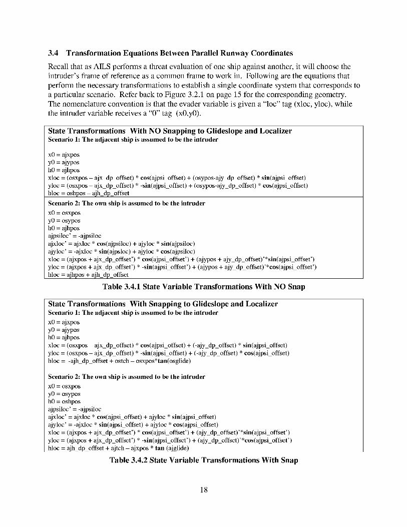
3.4 Transformation Equations Between Parallel Runway Coordinates
Recall that as AILS performs a threat evaluation of one ship against another, it will choose the
intruder's frame of reference as a common frame to work in. Following are the equations that
perform the necessary transformations to establish a single coordinate system that corresponds to
a particular scenario. Refer back to Figure 3.2.1 on page 15 for the corresponding geometry.
The nomenclature convention is that the evader variable is given a "loc" tag (xloc, yloc), while
the intruder variable receives a "0" tag (x0,y0).
State Transformations With NO Snapping to Glideslope and LocalizerScenario 1: The adjacent ship is assumed to be the intruder
x0 = ajxpos
y0 = ajyposh0 = ajhpos
xloc = (osxpos - ajx_dp_offset) * cos(ajpsi_offset) + (osypos-ajy_dp_offset) * sin(ajpsi_offset)yloc = (osxpos - ajx_dp_offset) * -sin(ajpsi_offset) + (osypos-ajy_dp_offset) * cos(ajpsi_offset)
hloc = oshpos - ajh_dp_offset
Scenario 2: The own ship is assumed to be the intruder
x0 = osxposy0 = osypos
h0 = ajhposajpsiloc' = -ajpsiloc
ajxloc' = ajxloc * cos(ajpsiloc) + ajyloc * sin(ajpsiloc)
ajyloc' = -ajxloc * sin(ajpsloc) + ajyloc * cos(ajpsiloc)xloc = (ajxpos + ajx_dp_offset') * cos(ajpsi_offset') + (ajypos + ajy_dp_offset)'*sin(ajpsi_offset')
yloc = (ajxpos + ajx_dp_offset') * -sin(ajpsi_offset') + (ajypos + ajy_dp_offset)'*cos(ajpsi_offset')hloc = ajhpos + ajh_dp_offset
Table 3.4.1 State Variable Transformations With NO Snap
State Transformations With Snapping to Glideslope and Localizer
Scenario 1: The adjacent ship is assumed to be the intruder
x0 = ajxposyO = ajypos
h0 = ajhposxloc = (osxpos - ajx_dp_offset) * cos(ajpsi_offset) + (-ajy_dp_offset) * sin(ajpsi_offset)
yloc = (osxpos - ajx_dp_offset) * -sin(ajpsi_offset) + (-ajy_dp_offset) * cos(ajpsi_offset)
hloc = -ajh_dp_offset + ostch - osxpos*tan(osglide)
Scenario 2: The own ship is assumed to be the intruder
x0 = osxposy0 = osypos
hO = oshposajpsiloc' = -ajpsiloc
ajxloc' = ajxloc * cos(ajpsi_offset) + ajyloc * sin(ajpsi_offset)
ajyloc' = -ajxloc * sin(ajpsi_offset) + ajyloc * cos(ajpsi_offset)
xloc = (ajxpos + ajx_dp_offset') * cos(ajpsi_offset') + (ajy_dp_offset)'*sin(ajpsi_offset')yloc = (ajxpos + ajx_dp_offset') * -sin(ajpsi_offset') + (ajy_dp_offset)'*cos(ajpsi_offset')
hloc = ajh_dp_offset + ajtch - ajxpos * tan (ajglide)
Table 3.4.2 State Variable Transformations With Snap
18
Thevariablesintroducedabove(ajglide,ajtch,osglide,andostch)aretheglideslopeanglesandthresholdcrossingheightsthatdefinetheglidepathsthat theaircraftaresnappedto. Thesevariablesaredescribedfurther in thefollowing sectionwheretherelevanceof approachdatatotheAILS algorithmis discussed.
3.5 Use of Approach Data to Perform Conversion to AILS Coordinates
AILS is confined to a parallel runway approach scenario. Approach data is therefore a vital and
integral part of the AILS algorithm. This is especially true since AILS performs "snapping" to
glide-slopes and localizers which requires precise knowledge of where the runways and
approaches are.
Depending on the specific implementation of AILS, the coordinate transformation from
latitude, longitude, and altitude to the local runway coordinate frame requires knowledge of the
local runway and approach. The software that performed these conversions for the flight tests
used the convention that was defined according to conventions adopted by Honeywell's
SLS/GNSSU systems.
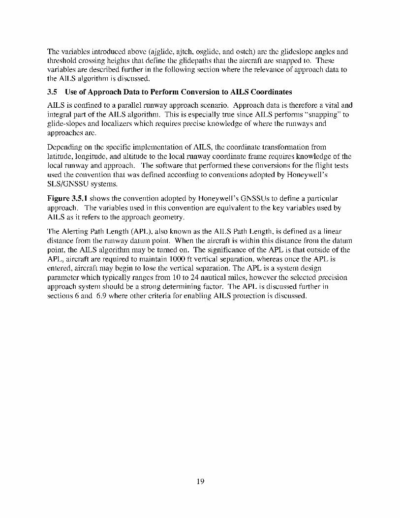
Figure 3.5.1 shows the convention adopted by Honeywell's GNSSUs to define a particular
approach. The variables used in this convention are equivalent to the key variables used by
AILS as it refers to the approach geometry.
The Alerting Path Length (APL), also known as the AILS Path Length, is defined as a linear
distance from the runway datum point. When the aircraft is within this distance from the datum
point, the AILS algorithm may be turned on. The significance of the APL is that outside of the
APL, aircraft are required to maintain 1000 ft vertical separation, whereas once the APL is
entered, aircraft may begin to lose the vertical separation. The APL is a system design
parameter which typically ranges from 10 to 24 nautical miles, however the selected precision
approach system should be a strong determining factor. The APL is discussed further in
sections 6 and 6.9 where other criteria for enabling AILS protection is discussed.
19
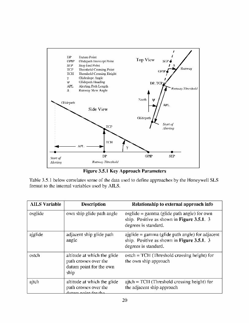
DP Datum Point
GPIP Glidepath Intercept Point
SEP Stop End Point
TCP Tbxeshold Crossing Point
TCH Ttueshold Crossing Height
7 Glideslope Angle
Glidepath Heading
APL Alerting Path Length
A Runway Slew Angle
Glidepath
Side View
TCP
Top View SEP _ It /
_Runway
GPI_V
DP, TCP_._
/ _ _ Runway Threshold
I/
N°rthI V //APL
Glidepath_ APL
/- 2,7,o
TCH
APL --
DPStart of
Alerting Runway Threshold
GPIP SEP
Figure 3.5.1 Key Approach Parameters
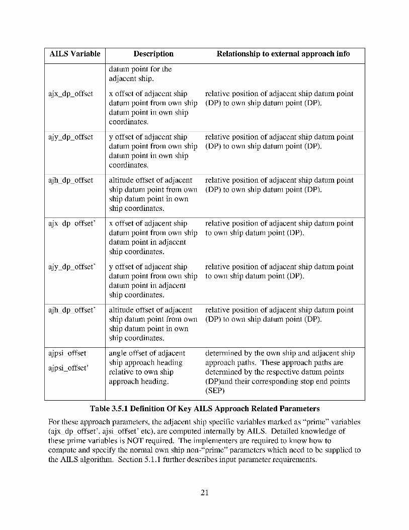
Table 3.5.1 below correlates some of the data used to define approaches by the Honeywell SLS
format to the internal variables used by AILS.
AILS Variable
osglide
ajglide
ostch
ajtch
Description
own ship glide path angle
adjacent ship glide path
angle
altitude at which the glide
path crosses over the
datum point for the own
ship
altitude at which the glide
path crosses over the
Relationship to external approach info
osglide = gamma (glide path angle) for own
ship. Positive as shown in Figure 3.5.1. 3
degrees is standard.
ajglide = gamma (glide path angle) for adjacent
ship. Positive as shown in Figure 3.5.1. 3
degrees is standard.
ostch = TCH (Threshold crossing height) for
the own ship approach
ajtch = TCH (Threshold crossing height) for
the adjacent ship approach
20
AILS Variable Description Relationship to external approach info
datum point for the
adjacent ship.
ajx_dp_offset
ajy_dp_offset
ajh_dp_offset
ajx_dp_offset'
ajy_dp_offset'
ajh_dp_offset'
ajpsi_offset
ajpsi_offset'
x offset of adjacent ship
datum point from own ship
datum point in own ship
coordinates.
y offset of adjacent ship
datum point from own ship
datum point in own shipcoordinates.
altitude offset of adjacent
ship datum point from own
ship datum point in own
ship coordinates.
x offset of adjacent ship
datum point from own ship
datum point in adjacent
ship coordinates.
y offset of adjacent ship
datum point from own ship
datum point in adjacent
ship coordinates.
altitude offset of adjacent
ship datum point from own
ship datum point in own
ship coordinates.
angle offset of adjacent
ship approach heading
relative to own ship
approach heading.
relative position of adjacent ship datum point
(DP) to own ship datum point (DP).
relative position of adjacent ship datum point
(DP) to own ship datum point (DP).
relative position of adjacent ship datum point
(DP) to own ship datum point (DP).
relative position of adjacent ship datum point
to own ship datum point (DP).
relative position of adjacent ship datum point
to own ship datum point (DP).
relative position of adjacent ship datum point
(DP) to own ship datum point (DP).
determined by the own ship and adjacent ship
approach paths. These approach paths are
determined by the respective datum points
(DP)and their corresponding stop end points
(SEe)
Table 3.5.1 Definition Of Key AILS Approach Related Parameters
For these approach parameters, the adjacent ship specific variables marked as "prime" variables
(ajx_dp_offset', ajsi_offset' etc), are computed internally by AILS. Detailed knowledge of
these prime variables is NOT required. The implementers are required to know how to
compute and specify the normal own ship non-"prime" parameters which need to be supplied to
the AILS algorithm. Section 5.1.1 further describes input parameter requirements.
21
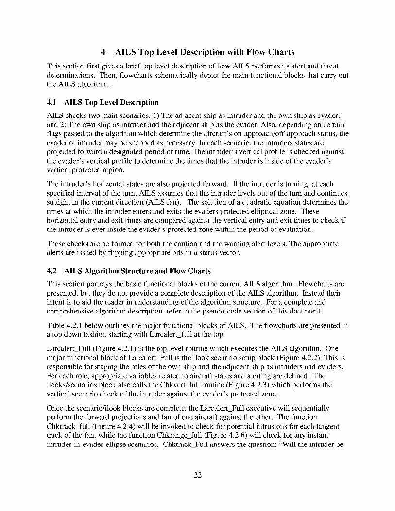
4 AILS Top Level Description with Flow Charts
This section first gives a brief top level description of how AILS performs its alert and threat
determinations. Then, flowcharts schematically depict the main functional blocks that carry out
the AILS algorithm.
4.1 AILS Top Level Description
AILS checks two main scenarios: 1) The adjacent ship as intruder and the own ship as evader;
and 2) The own ship as intruder and the adjacent ship as the evader. Also, depending on certain
flags passed to the algorithm which determine the aircraft's on-approach/off-approach status, the
evader or intruder may be snapped as necessary. In each scenario, the intruders states are
projected forward a designated period of time. The intruder's vertical profile is checked against
the evader's vertical profile to determine the times that the intruder is inside of the evader's
vertical protected region.
The intruder's horizontal states are also projected forward. If the intruder is turning, at each
specified interval of the turn, AILS assumes that the intruder levels out of the turn and continues
straight in the current direction (AILS fan). The solution of a quadratic equation determines the
times at which the intruder enters and exits the evaders protected elliptical zone. These
horizontal entry and exit times are compared against the vertical entry and exit times to check if
the intruder is ever inside the evader's protected zone within the period of evaluation.
These checks are performed for both the caution and the warning alert levels. The appropriate
alerts are issued by flipping appropriate bits in a status vector.
4.2 AILS Algorithm Structure and Flow Charts
This section portrays the basic functional blocks of the current AILS algorithm. Flowcharts are
presented, but they do not provide a complete description of the AILS algorithm. Instead their
intent is to aid the reader in understanding of the algorithm structure. For a complete and
comprehensive algorithm description, refer to the pseudo-code section of this document.
Table 4.2.1 below outlines the major functional blocks of AILS. The flowcharts are presented in
a top down fashion starting with Larcalertfull at the top.
Larcalert Full (Figure 4.2.1) is the top level routine which executes the AILS algorithm. One
major functional block of Larcalert Full is the ilook scenario setup block (Figure 4.2.2). This is
responsible for staging the roles of the own ship and the adjacent ship as intruders and evaders.
For each role, appropriate variables related to aircraft states and alerting are defined. The
ilooks/scenarios block also calls the Chkvertfull routine (Figure 4.2.3) which performs the
vertical scenario check of the intruder against the evader's protected zone.
Once the scenario/ilook blocks are complete, the Larcalert Full executive will sequentially
perform the forward projections and fan of one aircraft against the other. The function
Chktrack_full (Figure 4.2.4) will be invoked to check for potential intrusions for each tangent
track of the fan, while the function Chkrange_full (Figure 4.2.6) will check for any instant
intruder-in-evader-ellipse scenarios. Chktrack Full answers the question: "Will the intruder be
22
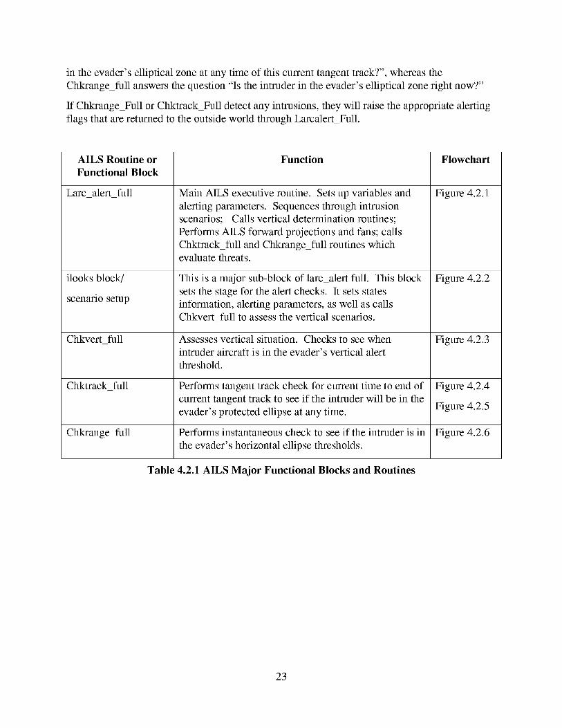
in theevader'selliptical zoneat anytimeof this currenttangenttrack?",whereastheChkrange_fullanswersthequestion"Is theintruder in theevader'selliptical zoneright now?"
If ChkrangeFull or Chktrack_Fulldetectanyintrusions,theywill raisethe appropriatealertingflagsthat arereturnedto theoutsideworld throughLarcalert_Full.
AILS Routine or
Functional Block
Larc_alert_full
ilooks block/
scenario setup
Chkvert_full
Chktrack_full
Chkrange_full
Function
Main AILS executive routine. Sets up variables and
alerting parameters. Sequences through intrusion
scenarios; Calls vertical determination routines;
Performs AILS forward projections and fans; calls
Chktrack_full and Chkrange_full routines which
evaluate threats.
This is a major sub-block of larc_alert full. This block
sets the stage for the alert checks. It sets states
information, alerting parameters, as well as calls
Chkvertfull to assess the vertical scenarios.
Assesses vertical situation. Checks to see when
intruder aircraft is in the evader's vertical alert
threshold.
Performs tangent track check for current time to end of
current tangent track to see if the intruder will be in the
evader's protected ellipse at any time.
Performs instantaneous check to see if the intruder is in
the evader's horizontal ellipse thresholds.
Flowchart
Figure 4.2.1
Figure 4.2.2
Figure 4.2.3
Figure 4.2.4
Figure 4.2.5
Figure 4.2.6
Table 4.2.1 AILS Major Functional Blocks and Routines
23
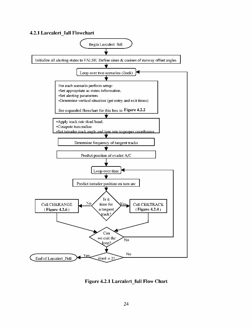
4.2.1 Larcalert full Flowcharti
C Begin LarcalertIfull )
+I Initialize all alerting states to FALSE. Define sines & cosines of runway offset angles I
Loop over two scenarios (ilook) ]41
For each scenario perform setup:
•Set appropriate ac states information.
•Set alerting parameters
•Determine vertical situation (get entry and exit times)
See expanded flowchart for this box in Figure 4.2.2
I .Apply track rate dead band.•Compute turn radius
•,_et intruder track angle and turn rate to proper eoordinate._
I Determine frequency of tangent tracks
I Predict position of evader A/C
[Loopovert eI I
I Predict intruder position on turn arc I
Call CHKRANGE _N° es Call CHKTRACK
(Figure 4.2.6) I" " " (Figure 4.2.4)
No
fk_End of Larcalert_Full_
Figure 4.2.1 Larcalert_full Flow Chart
24
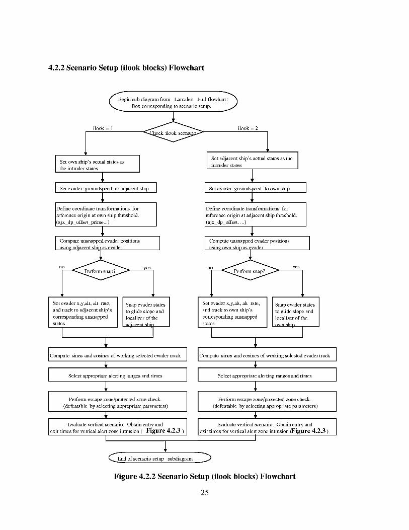
4.2.2 Scenario Setup (ilook blocks) Flowchart
gin sub diagram fi'om Larcalert Full flowhart.'_
Box corresponding to scenalio setup. J
ilook = 1 _ ilook = 2
I et own ship's actual states asthe intruder states
I_vad_r_ro.mds.d_oad_ac_n_s_pI
Define coordinate transformations for
reference origin at own ship thieshold.
(ajx dp offset plime...)
I Iusin_ adiacent shhi as evader
Set evader x,y,alt, alt rate, Snap evader states
and track to adjacent ship's to glide slope and
corresponding unsnapped localizer of the
states adiaeont _hi
Set adjacent ship's actual states as the //
Jintruder states
,LI Set evader gro_mdspeed to own ship
Define coordinate transformations for
reference origin at adjacent ship thieshold.
(ajx dp offset....)
I °mp 'msnap- vad rp°si °nsIusine own shio as evader
Set evader x,y,alt, alt rate, Snap evader states
and track to own ship's to glide slope and
corresponding unsnapped localizer of the
states own _hin
Compute sines and cosines of working selected evader track
Select appropriate almting ranges and times
Perform escape zone/protected zone check.
(defeatable by selecting appropriate parameters)
Evaluate vertical scenatio. Obtain ently and Iexit times fol vmtical almt zone intrusion ( Figure 4.2.3 ) ] exit Evaluate vertical scenatio. Obtain ently andtimes for vertical alto* zone intrusion (Figure 4.2.3 )
I
Compute sines and cosines of working selected evader track
I
Select appropriate alerting ranges and times I1
i
Perform escape zone/protected zone check. I(defeatable by selecting appropriate parameters) I
I
CEnd of scenario setup subdiagram "_
Figure 4.2.2 Scenario Setup (ilook blocks) Flowchart
25
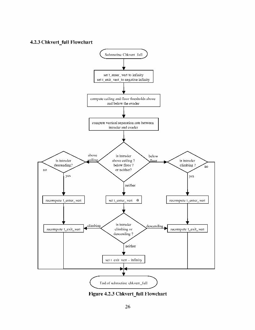
4.2.3Chkvert full Flowchart
Subroutine Ctkkvert full_
set t enter vert to infinity
set t exit vert to negative infinity
I
compute ceiling and floor ttn'esholds above Iand below the evader I
compute vertical separation rate between
intruder and evader
above _ below
no no
I yc_ _er _yes
Irecomp_*e*en*ervet*I Ise**en*ervet*01 Irecomp_*e*en*ervet*I
exit L"climbing escending _ exit vert
recompute vert I"q "_e12eT_2g12 r.9_ recompute I
neittler
I settexitvert"_fH_i_I
End of subroutine ctkkvert full )
Figure 4.2.3 Chkvert_full Flowchart
26
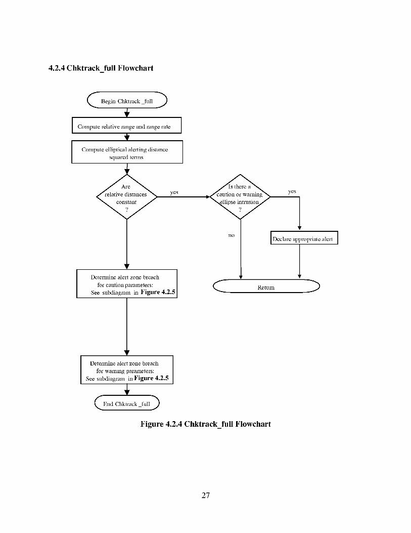
4.2.4 Chktrack full Flowchart
Begin Ctkktrack full
I Compute relative range and range rate
Compute elliptical alerting distance
squared temls
yes
IDetemline alert zone breach I
Ifor caution parameters:
See subdiagram in Figure 4.2.5<
no
yes
lIDeclare appropnatealert I
1Remm --)
Detemline alert zone breach
for warning parameters:
See subdiagram in Figure 4.2.5
End Chktrack full )
Figure 4.2.4 Chktrack_full Flowchart
27
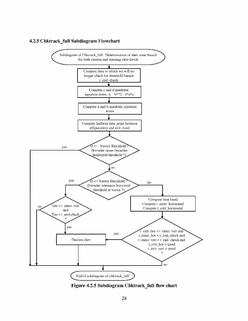
4.2.5 Chktrack_full Subdiagram Flowchart
no
I Declare alert
bdiagram of Ctkkn'ackfull: Detemfination of alert zone breach_
for both caution and warning alert levels J
÷Compute time at which we will no
longer check for ttn'eshold breach
t end check
÷Compute c and d quach'atic
equation temls d b**2 4*a*c
Compute a and b quadratic equationtelTI1S
I Compute halfway time point betweenellipse entry and exit (tau)
yes
no
1Compute time band I
i
Compute t enter horizontal ICompute t exit horizontal
End of subdiagram of ctkkn'ack full_
Figure 4.2.5 Subdiagram Chktrack_full flow chart
28
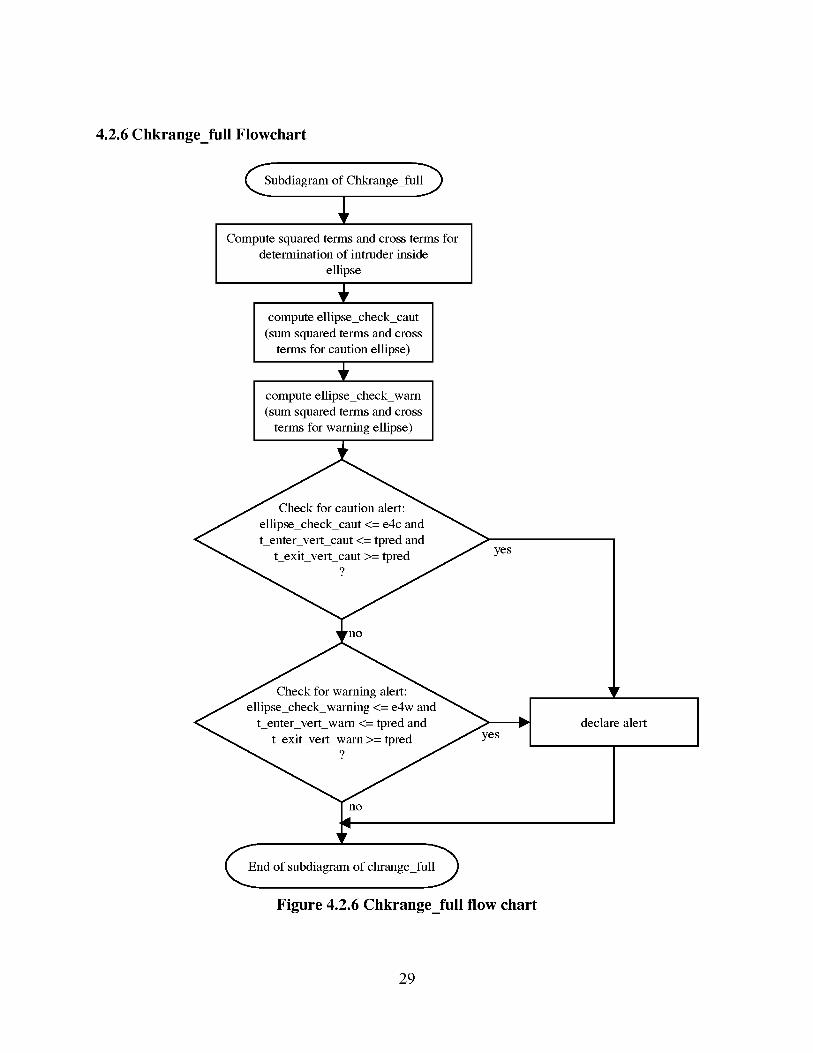
4.2.6 Chkrange_full Flowchart
Subdiagram of Chkrange_full_
Compute squared terms and cross terms fordetermination of intruder inside
ellipse
+compute ellipse_check_cant
(sum squared terms and cross
terms for caution ellipse)
+compute ellipse_check_warn
(sum squared terms and cross
terms for warning ellipse)
Check for caution alert:
ellipse_check_cant <= e4c and
t enter vert_caut <= tpred and
t exit vert_cant >= tpred?
rno
Check for warning alert:ellipse_check_warning <= e4w and
t_enter_vert_wam <= tpred and
t_exit_vert_warn >= tpred?
yes
yes
declare alert
End of subdiagram of chrange_full_
Figure 4.2.6 Chkrange_full flow chart
29
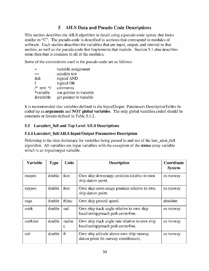
5 AILS Data and Pseudo Code Descriptions
This section describes the AILS algorithm in detail using a pseudo-code syntax that looks
similar to "C". The pseudo-code is described in sections that correspond to modules of
software. Each section describes the variables that are input, output, and internal to that
section, as well as the pseudo-code that implements that module. Section 5.1 also describessome data that is common to all of the modules.
Some of the conventions used in the pseudo-code are as follows:
= variable assignment
equality test
&& logical AND
II logical OR
/* text */ comments
*variable use pointer to variable
&variable get pointer to variable
It is recommended that variables defined in the Input/Output Parameters DescriptionTables be
coded up as arguments and NOT global variables. The only global variables coded should beconstants or literals defined in Table 5.1.2.
5.1 Larcalert_full and Top Level AILS Descriptions
5.1.1 Larcalert_full/AILS Input/Output Parameters Description
Following is the data dictionary for variables being passed in and out of the larc_alert_full
algorithm. All variables are input variables with the exception of the status array variable
which is an input/output variable.
Variable Type Units Description Coordinate
System
osxpos double feet Own ship downrange position relative to own os runway
ship datum point.
osypos double feet Own ship cross-range position relative to own os runway
ship datum point.
osgs double ft/sec Own ship ground speed, absolute
ostrk double rad Own ship track angle relative to own ship os runway
localizer/approach path centerline.
ostrkdot double rad/se Own ship track angle rate relative to own ship os runway
c localizer/approach path centerline.
osh double ft Own ship altitude above own ship runway os runway
datum point (in runway coordinates).
30
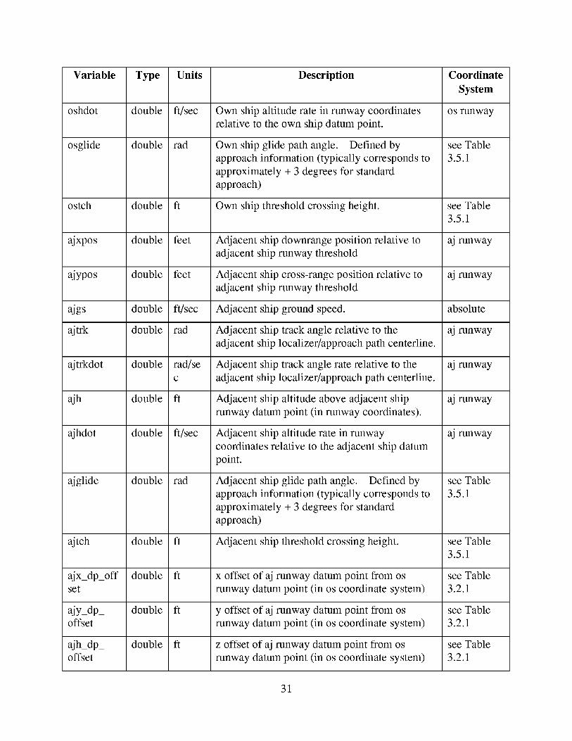
Variable
oshdot
osglide
ostch
ajxpos
ajypos
ajgs
ajtrk
ajtrkdot
ajh
ajhdot
ajglide
ajtch
_x_dp_off
set
ajy_dp_offset
ajh_dp_offset
Type
double
double
double
double
double
double
double
double
double
double
double
double
double
double
double
Units
ft/sec
rad
ft
feet
feet
ft/sec
rad
rad/se
c
ft
ft/sec
rad
ft
ft
ft
ft
Description
Own ship altitude rate in runway coordinates
relative to the own ship datum point.
Own ship glide path angle. Defined by
approach information (typically corresponds to
approximately + 3 degrees for standard
approach)
Own ship threshold crossing height.
Adjacent ship downrange position relative to
adjacent ship runway threshold
Adjacent ship cross-range position relative to
adjacent ship runway threshold
Adjacent ship ground speed.
Adjacent ship track angle relative to the
adjacent ship localizer/approach path centerline.
Adjacent ship track angle rate relative to the
adjacent ship localizer/approach path centerline.
Adjacent ship altitude above adjacent ship
runway datum point (in runway coordinates).
Adjacent ship altitude rate in runway
coordinates relative to the adjacent ship datum
point.
Adjacent ship glide path angle. Defined by
approach information (typically corresponds to
approximately + 3 degrees for standard
approach)
Adjacent ship threshold crossing height.
x offset of aj runway datum point from os
runway datum point (in os coordinate system)
y offset of aj runway datum point from os
runway datum point (in os coordinate system)
z offset of aj runway datum point from os
runway datum point (in os coordinate system)
Coordinate
System
os runway
see Table
3.5.1
see Table
3.5.1
aj runway
aj runway
absolute
aj runway
aj runway
aj runway
aj runway
see Table
3.5.1
see Table
3.5.1
see Table
3.2.1
see Table
3.2.1
see Table
3.2.1
31
Variable Type Units Description Coordinate
System
ajpsi_ double rad Angle offset of adjacent runway approach path see Table
offset from the own runway approach path 3.2.1
aldst_e[10] double ft Elliptical alert range threshold vector
alvup[5] double ft Vertical alert range threshold above evader
vector.
alvdown[5] double ft Vertical alert range threshold below evadervector
altime[5] double ft Alert time threshold vector
protected_ double ft Protected escape zone vector parameters
esc[5]
trkratedb double rad/se Track rate deadband
c
turntime double sec Time duration with which to allow AILS to
project the current forward turn.
tstep double sec Time step search granularity for AILS fan.
status[100] int Vector containing alerting routine status as wellas other miscellaneous information.
intos_snap_
flag
aj_snap_
flag
int
Flag indicating that AILS should perform snap
of the own ship to the own ship's approach
path. If TRUE, snap; If FALSE, use actual
states of the own ship when checking for the
adjacent ship intrusion on the own ship.
Flag indicating that AILS should perform snap
of the adjacent ship to the adjacent ship's
approach path. If TRUE, snap; If FALSE, use
actual states for the adjacent ship when
checking for the own ship intrusion on the
adjacent ship.
Table 5.1.1 Larcalert_full/AILS Input Output Variables Data Dictionary
5.1.2 AILS Literals and Indices
The following class of variables are indices or literals that are used to access array elements
within the AILS algorithm. In a "C" language implementation they would be defined through
the use of the "C .... #define" statements. In Ada or other languages they could be either
32
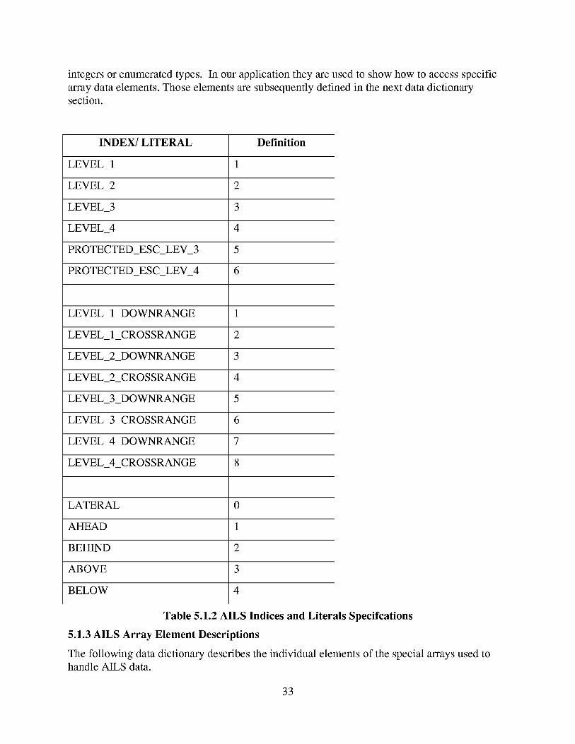
integersorenumeratedtypes. In ourapplicationtheyareusedto showhow to accessspecificarraydataelements.Thoseelementsaresubsequentlydefinedin thenext datadictionarysection.
INDEX/LITERAL Definition
LEVEL_I 1
LEVEL_2 2
LEVEL_3 3
LEVEL_4 4
PROTECTED_ES C_LEV_3 5
PROTECTED_ES C_LEV_4 6
LEVEL 1 DOWNRANGE 1
LEVEL 1 CROSSRANGE
LEVEL 2
LEVEL 2
LEVEL 3
LEVEL 3
LEVEL 4
LEVEL 4
DOWNRANGE
CROSSRANGE
DOWNRANGE
CROSSRANGE
DOWNRANGE
CROSSRANGE
2
3
4
5
6
7
8
LATERAL 0
AHEAD 1
BEHIND 2
ABOVE 3
BELOW 4
Table 5.1.2 AILS Indices and Literals Specifcations
5.1.3 AILS Array Element Descriptions
The following data dictionary describes the individual elements of the special arrays used tohandle AILS data.
33
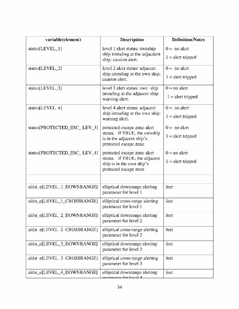
variable (element)
status [LEVEL_ 1]
status[LEVEL_2]
status[LEVEL_3]
status[LEVEL_4]
status[PROTECTED_ESC_ LEV_3]
status[PROTECTED_ESC_ LEV_4]
Description
level 1 alert status: ownship
ship intruding at the adjacdent
ship: caution alert.
level 2 alert status: adjacent
ship intruding at the own ship:caution alert.
level 3 alert status: own ship
intruding at the adjacent ship:
warning alert.
level 4 alert status: adjacent
ship intruding at the own ship:
warning alert.
protected escape zone alert
status. If TRUE, the ownship
is in the adjacent ship's
protected escape zone
protected escape zone alert
status. If TRUE, the adjacent
ship is in the own ship's
protected escape zone
aldst_e[LEVEL 1 DOWNRANGE] feet
1 CROSSRANGE]aldst_e[LEVEL
aldst_e[LEVEL 2 DOWNRANGE]
aldst_e[LEVEL 2 CROSSRANGE]
aldst_e[LEVEL 3 DOWNRANGE]
aldst_e[LEVEL 3 CROSSRANGE]
aldst_e[LEVEL 4 DOWNRANGE]
elliptical downrange alerting
parameter for level 1
elliptical cross-range alerting
parameter for level 1
elliptical downrange alerting
parameter for level 2
elliptical cross-range alerting
parameter for level 2
elliptical downrange alerting
parameter for level 3
elliptical cross-range alerting
parameter for level 3
elliptical downrange alerting
Definition/Notes
0 = no alert
1 = alert tripped
0 = no alert
1 = alert tripped
0 = no alert
1 = alert tripped
0 = no alert
1 = alert tripped
0 = no alert
1 = alert tripped
0 = no alert
1 = alert tripped
feet
feet
feet
feet
feet
feet
34
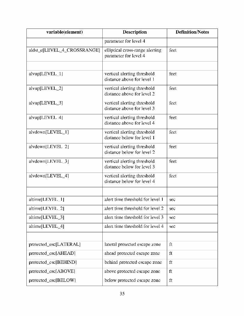
variable (element) Description Definition/Notes
parameter for level 4
aldsLe[LEVEL 4 CROSSRANGE] feetelliptical cross-range alerting
parameter for level 4
alvup[LEVEL_I] vertical alerting threshold feet
distance above for level 1
alvup[LEVEL_2] vertical alerting threshold feetdistance above for level 2
alvup[LEVEL_3] vertical alerting threshold feet
distance above for level 3
alvup[LEVEL_4] vertical alerting threshold feetdistance above for level 4
alvdown[LEVEL_l] vertical alerting threshold feet
distance below for level 1
alvdown[LEVEL_2] vertical alerting threshold feetdistance below for level 2
alvdown[LEVEL_3] vertical alerting threshold feet
distance below for level 3
alvdown[LEVEL_4] vertical alerting threshold feetdistance below for level 4
altime[LEVEL_l] alert time threshold for level 1 sec
altime[LEVEL_2] alert time threshold for level 2 sec
altime[LEVEL_3] alert time threshold for level 3 sec
altime[LEVEL_4] alert time threshold for level 4 sec
protected_esc[LATERAL] lateral protected escape zone ft
protected_esc[AHEAD] ahead protected escape zone ft
protected_esc[BEHIND] behind protected escape zone ft
protected_esc[ABOVE] above protected escape zone ft
protected_esc[BELOW] below protected escape zone ft
35
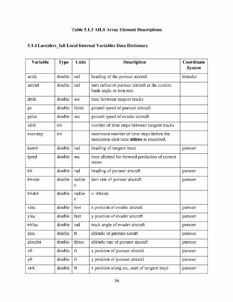
Table 5.1.3 AILS Array Element Descriptions
5.1.4 Larcalert_full Local Internal Variables Data Dictionary
Variable Type Units Description Coordinate
System
actrk double rad heading of the pursuer aircraft intruder
arcrad double rad turn radius of pursuer aircraft at the current
bank angle or turn rate.
dttrk double sec time between tangent tracks
gs double ft/sec ground speed of pursuer aircraft
gsloc double sec ground speed of evader aircraft
idtrk int number of time steps between tangent tracks
maxstep int maximum number of time steps before the
maximum alert time altime is exceeded.
tantrk double rad heading of tangent track pursuer
tpred double sec time allotted for forward prediction of current
states
trk double rad heading of pursuer aircraft pursuer
trkrate double rad/se turn rate of pursuer aircraft pursuer
c
trkdot double rad/se = -trkrate
c
xloc double feet x position of evader aircraft pursuer
yloc double feet y position of evader aircraft pursuer
trkloc double rad track angle of evader aircraft pursuer
zloc double ft altitude of pursuer airraft pursuer
zlocdot double ft/sec altitude rate of pursuer aircraft pursuer
xO double ft x position of pursuer aircraft pursuer
yO double ft y position of pursuer aircraft pursuer
xtrk double ft x position along arc, start of tangent track pursuer
36
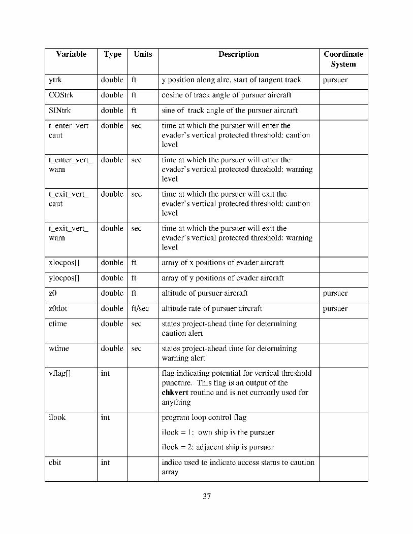
Variable Type Units Description Coordinate
System
ytrk double ft y position along alrc, start of tangent track pursuer
COStrk double ft cosine of track angle of pursuer aircraft
SINtrk double ft sine of track angle of the pursuer aircraft
t_enter very double sec time at which the pursuer will enter the
cant evader's vertical protected threshold: cautionlevel
t_enter very double sec time at which the pursuer will enter the
warn evader's vertical protected threshold: warning
level
t_exit very double sec time at which the pursuer will exit the
cant evader's vertical protected threshold: cautionlevel
t_exit very double sec time at which the pursuer will exit the
warn evader's vertical protected threshold: warninglevel
xlocpos[] double ft array of x positions of evader aircraft
ylocpos[] double ft array of y positions of evader aircraft
z0 double ft altitude of pursuer aircraft pursuer
z0dot double ft/sec altitude rate of pursuer aircraft pursuer
ctime double sec states project-ahead time for determining
caution alert
wtime double sec states project-ahead time for determining
warning alert
vflag[] int
ilook
cbit
int
int
flag indicating potential for vertical threshold
puncture. This flag is an output of the
chkvert routine and is not currently used for
anything
program loop control flag
ilook = 1: own ship is the pursuer
ilook = 2: adjacent ship is pursuer
indice used to indicate access status to caution
array
37
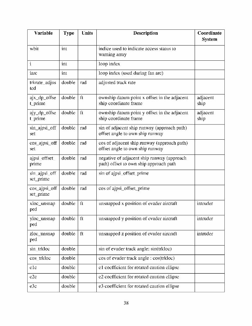
Variable Type Units Description Coordinate
System
wbit int indice used to indicate access status to
warning array
i int loop index
iarc int loop index (used during fan arc)
trkrate_adjus double rad adjusted track rateted
ajx_dp_offse double ft ownship datum point x offset in the adjacent adjacent
t prime ship coordinate frame ship
ajy_dp_offse double ft ownship datum point y offset in the adjacent adjacent
t prime ship coordinate frame ship
sin_ajpsi_off double rad sin of adjacent ship runway (approach path)
set offset angle to own ship runway
cos_ajpsi_off double rad cos of adjacent ship runway (approach path)
set offset angle to own ship runway
ajpsi_offset_ double rad negative of adjacent ship runway (approach
prime path) offset to own ship approach path
sin_ajpsi_off double rad sin of ajpsi_offset prime
set prime
cos_ajpsi_off double rad cos ofajpsi_offsetprime
set prime
xloc_unsnap double ft unsnapped x position of evader aircraft intruder
ped
yloc_unsnap double ft unsnapped y position of evader aircraft intruder
ped
zloc_unsnap double ft unsnapped z position of evader aircraft intruder
ped
sin_trkloc double sin of evader track angle: sin(trkloc)
cos_trkloc double cos of evader track angle : cos(trkloc)
elc double el coefficient for rotated caution ellipse
e2c double e2 coefficient for rotated caution ellipse
e3c double e3 coefficient for rotated caution ellipse
38

Variable Type Units Description Coordinate
System
e4c double e4 coefficient for rotated caution ellipse
elw double el coefficient for rotated warning ellipse
e2w double e2 coefficient for rotated warning ellipse
e3w double e3 coefficient for rotated warning ellipse
e4w double e4 coefficient for rotated warning ellipse
sin_trkloc_sq double sin of evader track squaredrd
cos_trkloc_s double cos of evader track squared
qrd
cdist_ double caution downrange ellipse parameter squared
downrange_
sqrd
wdist_ double warning downrange ellipse parameter squared
downrange_
sqrd
cdist_ double caution cross-range ellipse parameter squared
crossrrange_
sqrd
wdist_ double warning cross-range ellipse parameter squared
crossrrange_
sqrd
Table 5.1.4 AILS Local Variable Data Dictionary
5.1.5 Larcalert_full (AILS Executive) Algorithm Pseudo Code
Begin Larcalert_Full
/* Reset alert strings and flags */
status[LEVEL_l] = FALSE
status[LEVEL_2] = FALSE
status[LEVEL_3] = FALSE
status[LEVEL_4] = FALSE
status[PROTECTED_ESC LEV_3] = FALSE
39
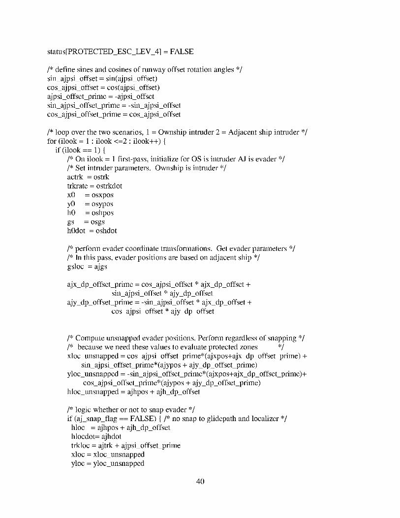
status[PROTECTED_ESCLEV_4] = FALSE
/* define sines and cosines of runway offset rotation angles */
sin_ajpsi_offset = sin(ajpsi_offset)
cos_ajpsi_offset = cos(ajpsi_offset)
ajpsi_offset prime =-ajpsi_offset
sin_ajpsi_offset prime =-sin_ajpsi_offset
cos_ajpsi_offset prime = cos_ajpsi_offset
/* loop over the two scenarios, 1 = Ownship intruder 2 = Adjacent ship intruder */
for (ilook = 1 ; ilook <=2 ; ilook++) {
if (ilook == 1) {
/* On ilook = 1 first-pass, initialize for OS is intruder AJ is evader */
/* Set intruder parameters. Ownship is intruder */actrk = ostrk
trkrate = ostrkdot
x0 = osxpos
y0 = osypos
h0 = oshpos
gs = osgsh0dot = oshdot
/* perform evader coordinate transformations. Get evader parameters */
/* In this pass, evader positions are based on adjacent ship */
gsloc = ajgs
ajx_dp_offset_prime = cos_ajpsi_offset * ajx_dp_offset +
sin_ajpsi_offset * ajy_dp_offset
ajy_dp_offset prime = -sin_ajpsi_offset * ajx_dp_offset +
cos_ajpsi_offset * ajy_dp_offset
/* Compute unsnapped evader positions. Perform regardless of snapping */
/* because we need these values to evaluate protected zones */
xloc_unsnapped = cos_ajpsi_offsetprime*(ajxpos+ajx_dp_offset_prime) +
sin_ajpsi_offset_prime*(ajypos + ajy_dp_offsetprime)
yloc_unsnapped =-sin_ajpsi_offset prime*(ajxpos+ajx_dp_offset prime)+
cos_ajpsi_offsetprime*(ajypos + ajy_dp_offset_prime)
hloc_unsnapped = ajhpos + ajh_dp_offset
/* logic whether or not to snap evader */
if (aj_snap_flag == FALSE) {/* no snap to glidepath and localizer */
hloc = ajhpos + ajh_dp_offset
hlocdot= ajhdot
trkloc = ajtrk + ajpsi_offset prime
xloc = xloc_unsnapped
yloc = yloc_unsnapped
40
} else {/* snap to glidespath and localizer */
/* assume threshold location 1000 ft from gpip */
hloc = ajh_dp_offset + ajtch - ajxpos * tan(ajglide)
hlocdot= -gsloc * tan(ajglide)
trkloc = ajpsi_offset prime
xloc = cos_ajpsi_offset_prime*(ajxpos+ajx_dp_offset_prime) +
sin_ajpsi_offset prime* ajy_dp_offset_prime
yloc = -sin_ajpsi_offsetprime*(ajxpos+ajx_dp_offseyprime)+
cos_ajp si_offsetprime*ajy_dp_offset prime
}/* trkloc's snapped/unsnapped status is dependent on snap_flag */
sin_trkloc = sin(trkloc)
cos_trkloc = cos(trkloc)
sin_trkloc_sqrd = sin_trkloc * sin_trkloc
cos_trkloc_sqrd = cos_trkloc * cos_trkloc
/* set elliptical alerting parameters */
cdist_downrange_sqrd = aldst_e[LEVEL 1 DOWNRANGE] *
aldste[LEVEL 1 DOWNRANGE]
cdist_crossrange_sqrd = aldst_e[LEVEL 1 CROSSRANGE] *
aldst_e[LEVEL 1 CROSSRANGE]
wdistdownrange_sqrd = aldst_e[LEVEL 3 DOWNRANGE] *
aldste[LEVEL 3 DOWNRANGE]
wdistcrossrange_sqrd = aldst_e[LEVEL 3 CROSSRANGE] *
aldst_e[LEVEL 3 CROSSRANGE]
e4c = cdistdownrange_sqrd * cdistcrossrange_sqrd
e4w = wdist_downrange_sqrd * wdist_crossrange_sqrd
elc = (cdist_downrange_sqrd*sin_trkloc_sqrd + cdist_crossrange_sqrd*cos_trkloc_sqrd)
e2c = (cdistdownrange_sqrd-cdisycrossrange_sqrd)*2.0*cos_trkloc*sin_trkloc
e3c = (cdistdownrange_sqrd*cos_trkloc_sqrd + cdistcrossrange_sqrd*sin_trkloc_sqrd)
elw = (wdistdownrange_sqrd*sin_trkloc_sqrd +
wdist_crossrange_sqrd*cos_trkloc_sqrd)
e2w = (wdistdownrange_sqrd-wdist_crossrange_sqrd)*2.0*cos_trkloc*sin_trkloc
e3w = (wdistdownrange_sqrd*cos_trkloc_sqrd +
wdistcrossrange_sqrd* sin_trkloc_sqrd)
/* set alerting times */
ctime = altime[LEVEL_l]
wtime = altime[LEVEL 3]
cbit = LEVEL_I
wbit = LEVEL_3
/* Check for esc zone violation of adjacent ship */
41
/* Perform this here because ownship coordinate system is available */
if ((xloc_unsnapped < osxpos + protected_esc[AHEAD]) &&
(xloc_unsnapped > osxpos - protected_esc[BEHIND]) &&
(hloc_unsnapped < oshpos + protected_esc[ABOVE]) &&
(hloc_unsnapped > oshpos - protected_esc[BELOW])) {
if (ajy_dp_offset > 0.0) { /* The adjacent ship runway is on the right */
if (yloc_unsnapped < (osypos+protected_esc[LATERAL])) {
status[LEVEL_4] = TRUE
status[PROTECTED_ESC LEV_4] = TRUE
} else if (ajy_dp_offset < 0.0) {/*The adjacent ship runway is on the left*/
if (yloc_unsnapped > (osypos-protected_esc[LATERAL])) {
status[LEVEL 4] = TRUE
status[PROTECTED_ESC LEV_4] = TRUE
}}
/* Get caution vertical alerting threshold status and times */
chkvertfull(hloc,hlocdot, h0, h0dot, alvup[1], alvdown[1],
&t_enter vert_caut, &t_exit vert_caut, &vflag[1])
/* Get warning vertical alerting threshold status and times */
chkvertfull(hloc,hlocdot, h0, h0dot, alvup[3], alvdown[3],
&t_enter vert_warn, &t_exit vert_warn, &vflag[3])
} else {
/* On ilook = 2, 2nd pass, initialize for AJ is intruder OS is evader */
/* Set intruder parameters */
actrk = ajtrk
trkrate = ajtrkdot
x0 = ajxpos
y0 = ajypos
h0 = ajhpos
gs = ajgs
h0dot = ajhdot
/* Perform evader coordinate transformations. Compute evader parameters */
/* In this pass, use own ship as evader */
gsloc = osgs
/* Compute unsnapped evader positions. Perform regardless of snapping */
/* because we need these values to evaluate protected zones. */
xloc_unsnapped = cos_ajpsi_offset * (osxpos-ajx_dp_offset) +
42
sin_ajpsi_offset* (osypos-ajy_dp_offset)yloc_unsnapped= -sin_ajpsi_offset* (osxpos-ajx_dp_offset)+
cos_ajpsi_offset* (osypos-ajy_dp_offset)hloc_unsnapped= oshpos
/* logic whether or not to snap evader */
if (os_snap_flag == FALSE) {/* no snap to glidepath and localizer */
hloc = oshpos- ajh_dp_offsethlocdot= oshdot
trkloc = ostrk + ajpsi_offset
xloc = xloc_unsnapped
yloc = yloc_unsnapped
} else {
/* snap to glidepath and localizer */
/* assume threshold location 1000 ft from gpip */
hloc = -ajh_dp_offset + ostch - osxpos*tan(osglide)
hlocdot= -osgs * tan(osglide)
trkloc = ajpsi_offset
xloc = cos_ajpsi_offset * (osxpos-ajx_dp_offset) +
sin_ajpsi_offset * (-ajy_dp_offset)
yloc = -sin_ajpsi_offset * (osxpos-ajx_dp_offset) +
cos_ajpsi_offset * (-ajy_dp_offset)
/* trkloc's snapped/unsnapped status is dependent on snap_flag */
sin_trkloc = sin(trkloc)
cos_trkloc = cos(trkloc)
sin_trkloc_sqrd = sin_trkloc * sin_trkloc
cos_trkloc_sqrd = cos_trkloc * cos_trkloc
/* set elliptical alerting parameters */
cdist_downrange_sqrd = aldst_e[LEVEL 2 DOWNRANGE] *
aldste[LEVEL 2 DOWNRANGE]
cdist_crossrange_sqrd = aldst_e[LEVEL 2 CROSSRANGE] *
aldst_e[LEVEL 2 CROSSRANGE]
wdistdownrange_sqrd = aldst_e[LEVEL 4 DOWNRANGE] *
aldste[LEVEL 4 DOWNRANGE]
wdistcrossrange_sqrd = aldst_e[LEVEL 4 CROSSRANGE] *
aldst_e[LEVEL 4 CROSSRANGE]
e4c = cdistdownrange_sqrd * cdistcrossrange_sqrd
e4w = wdist_downrange_sqrd * wdistcrossrange_sqrd
elc = (cdistdownrange_sqrd*sin_trkloc_sqrd + cdist_crossrange_sqrd*cos_trkloc_sqrd)
e2c = (cdist_downrange_sqrd-cdist_crossrange_sqrd)*2.0*cos_trkloc*sin_trkloc
e3c = (cdist_downrange_sqrd*cos_trkloc_sqrd + cdistcrossrange_sqrd*sin_trkloc_sqrd)
elw = (wdistdownrange_sqrd*sin_trkloc_sqrd +
43
wdist_crossrange_sqrd*cos_trkloc_sqrd)e2w= (wdistdownrange_sqrd-wdist_crossrange_sqrd)*2.0*cos_trkloc*sin_trkloce3w= (wdistdownrange_sqrd*cos_trkloc_sqrd+
wdistcrossrange_sqrd*sin_trkloc_sqrd)
/* set alerting times */
ctime = altime[LEVEL_2]
wtime = altime[LEVEL 4]
cbit = LEVEL_2
wbit = LEVEL 4
/* Check for protected_esc violation of own ship */
/* Perform this here because adjacent ship coordinate system is available */
if ((xloc_unsnapped < ajxpos + protected_esc[AHEAD]) &&
(xloc_unsnapped > ajxpos - protected_esc[BEHIND]) &&
(hloc_unsnapped < ajhpos + protected_esc[ABOVE]) &&
(hloc_unsnapped > ajhpos - protected_esc[BELOW])) {
if (ajy_dp_offset > 0.0) {/* The ownship ship runway is on the left */
if (yloc_unsnapped > (ajypos-protected_esc[LATERAL])) {
status[LEVEL_3] = TRUE
status[PROTECTED_ESC_LEV_3] = TRUE
}} else if (ajy_dp_offset < 0.0) {/*The ownship ship runway is on the right*/
if (yloc_unsnapped < (ajypos+protected_esc[LATERAL])) {
status[LEVEL_3] = TRUE
status[PROTECTED_ESC LEV_3] = TRUE
}
/* Get caution alerting threshold status and times */
chkvertfull(hloc,hlocdot, h0, h0dot, alvup[2], alvdown[2],
&t_enter vert_caut, &t_exit vert_caut, &vflag[2])
/* Get warning alerting threshold status and times */
chkvertfull(hloc,hlocdot, h0, h0dot, alvup[4], alvdown[4],
&t_enter vert_warn, &t_exit vert_warn, &vflag[4])
} /* End of ilook initialization block */
/* The following section deals with the intruder turn/turn rate profile */
/* Use track rate to determine turn rate */
/* Apply track rate dead band if necessary */
if (fabs(trkrate) < trkratedb) {
44
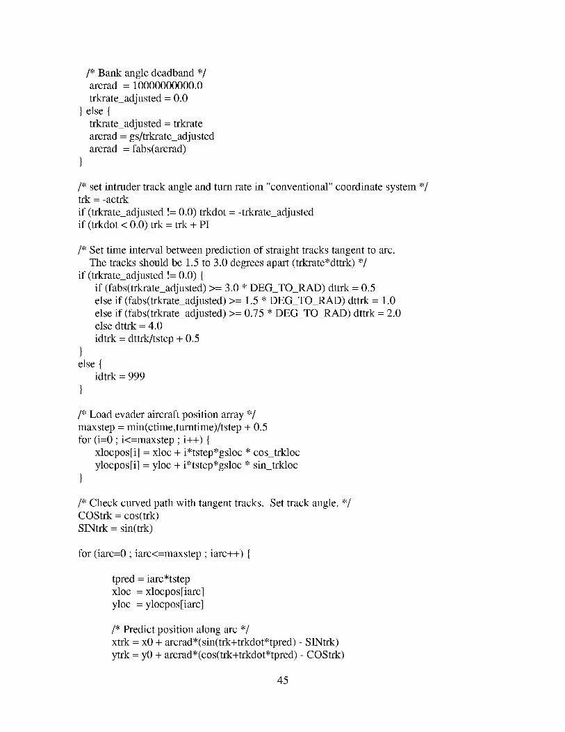
/* Bank angle deadband */arcrad = 10000000000.0
trkrate_adjusted = 0.0
} else {
trkrate_adjusted = trkrate
arcrad = gs/trkrate_adjusted
arcrad = fabs(arcrad)
}
/* set intruder track angle and turn rate in "conventional" coordinate system */trk = -actrk
if (trkrate_adjusted != 0.0) trkdot = -trkrate_adjusted
if (trkdot < 0.0) trk = trk + PI
/* Set time interval between prediction of straight tracks tangent to arc.
The tracks should be 1.5 to 3.0 degrees apart (trkrate*dttrk) */
if (trkrate_adjusted != 0.0) {
if (fabs(trkrate_adjusted) >= 3.0 * DEQTO_RAD) dttrk = 0.5
else if (fabs(trkrate_adjusted) >= 1.5 * DEQTO_RAD) dttrk = 1.0
else if (fabs(trkrate_adjusted) >= 0.75 * DEQTO_RAD) dttrk = 2.0else dttrk = 4.0
idtrk = dttrk/tstep + 0.5
}else {
idtrk = 999
}
/* Load evader aircraft position array */
maxstep = min(ctime,turntime)/tstep + 0.5
for (i=0 ; i<=maxstep ; i++) {
xlocpos[i] = xloc + i*tstep*gsloc * cos_trkloc
ylocpos[i] = yloc + i*tstep*gsloc * sin_trkloc
}
/* Check curved path with tangent tracks. Set track angle. */
COStrk = cos(trk)
SINtrk = sin(trk)
for (iarc=0 ; iarc<=maxstep ; iarc++) {
tpred = iarc*tstep
xloc = xlocpos[iarc]
yloc = ylocpos[iarc]
/* Predict position along arc */
xtrk = x0 + arcrad*(sin(trk+trkdot*tpred) - SINtrk)
ytrk = y0 + arcrad*(cos(trk+trkdot*tpred) - COStrk)
45
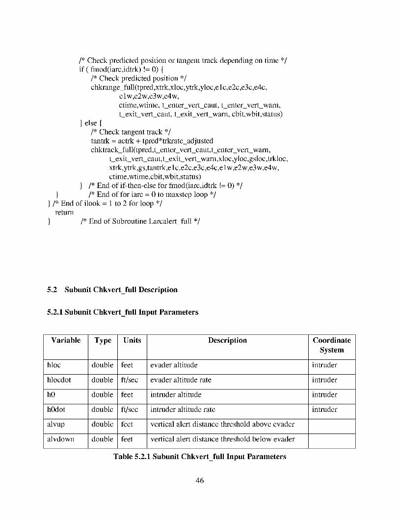
/* Check predicted position or tangent track depending on time */
if (fmod(iarc,idtrk) != 0) {
/* Check predicted position */
chkrange_full(tpred,xtrk,xloc,ytrk,yloc,elc,e2c,e3c,e4c,
elw,e2w,e3w,e4w,
ctime,wtime, tenter vert_caut, t_enter vert_warn,
texit_vert_caut, texit_verywarn, cbit,wbit, status)
} else {
/* Check tangent track */
tantrk = actrk + tpred*trkrate_adjusted
chktrack_full(tpred,tenter vert_caut,tenter vert_warn,
texit_vert_caut,t_exit vert_warn,xloc,yloc,gsloc,trkloc,
xtrk,ytrk,gs,tantrk,elc,e2c,e3c,e4c,elw,e2w,e3w,e4w,
ctime,wtime,cbit,wbit, status)
} /* End of if-then-else for fmod(iarc,idtrk != 0) */
} /* End of for iarc = 0 to maxstep loop */
}/* End of ilook = 1 to 2 for loop */return
} /* End of Subroutine Larcalert_full */
5.2 Subunit Chkvert_full Description
5.2.1 Subunit Chkvert_full Input Parameters
Variable Type Units Description Coordinate
System
hloc double feet evader altitude intruder
hlocdot double ft/sec evader altitude rate intruder
h0 double feet intruder altitude intruder
h0dot double ft/sec intruder altitude rate intruder
alvup double feet vertical alert distance threshold above evader
alvdown double feet vertical alert distance threshold below evader
Table 5.2.1 Subunit Chkvert_full Input Parameters
46
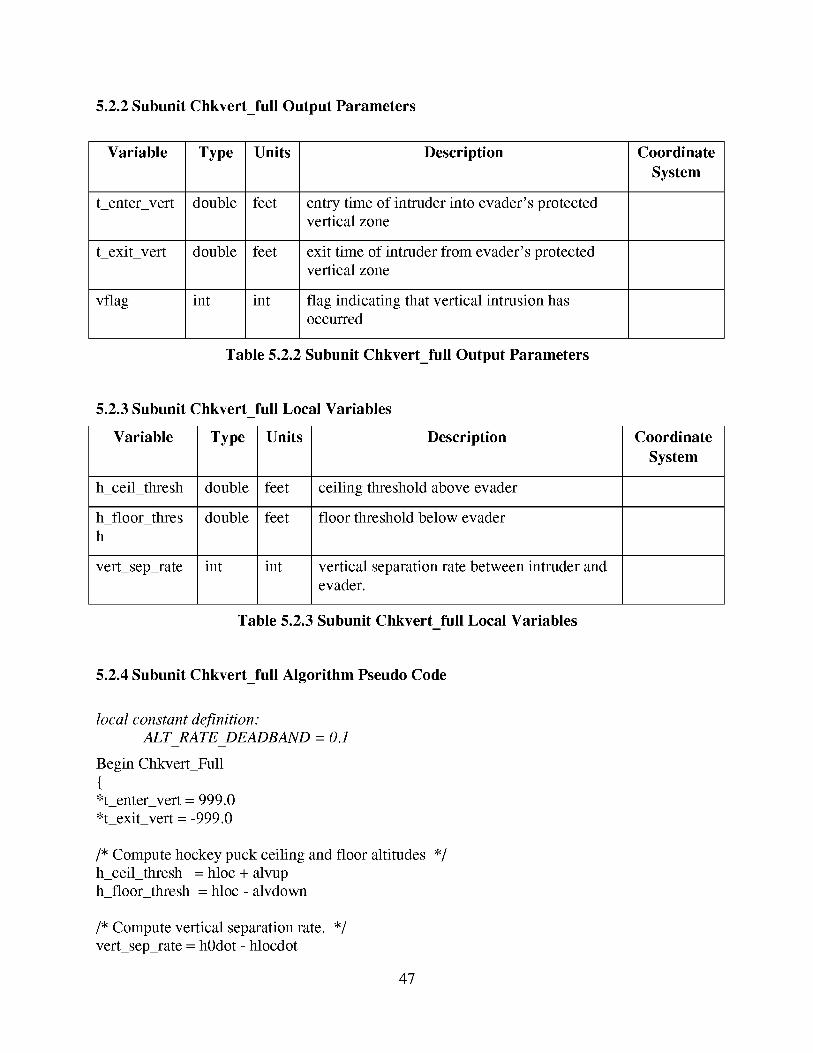
5.2.2 Subunit Chkvert_full Output Parameters
Variable
t_enter_vert
t_exit_vert
vflag
Type Units Description
double feet
double feet
int int
entry time of intruder into evader's protectedvertical zone
exit time of intruder from evader's protectedvertical zone
flag indicating that vertical intrusion has
occurred
Coordinate
System
Table 5.2.2 Subunit Chkvert_full Output Parameters
5.2.3 Subunit Chkvert full Local Variables
Variable Type Units Description
h_ceil_thresh double
h_floor_thres double
h
vert_sep_rate int
feet
feet
int
ceiling threshold above evader
floor threshold below evader
vertical separation rate between intruder and
evader.
Coordinate
System
Table 5.2.3 Subunit Chkvert full Local Variables
5.2.4 Subunit Chkvert_full Algorithm Pseudo Code
local constant definition:ALT RATE DEADBAND = 0.1
Begin Chkvert_Full
{*t_enter vert = 999.0
*t_exit_vert = -999.0
/* Compute hockey puck ceiling and floor altitudes */
h_ceil_thresh = hloc + alvuph_floor_thresh = hloc - alvdown
/* Compute vertical separation rate. */
vert_sep_rate = hOdot - hlocdot
47
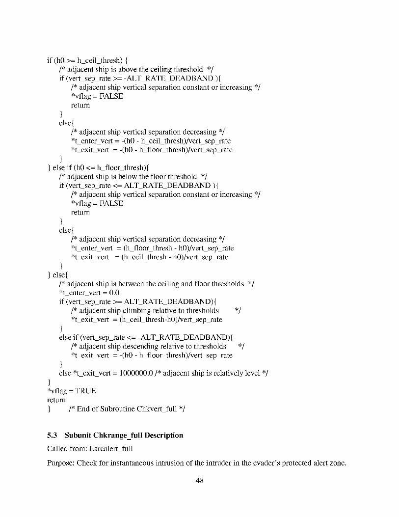
if (h0 >= h_ceil_thresh) {
/* adjacent ship is above the ceiling threshold */
if (vert_sep_rate >= -ALT RATE_DEADBAND ) {
/* adjacent ship vertical separation constant or increasing */
*vflag = FALSEreturn
else{
/* adjacent ship vertical separation decreasing */
*t_enter vert = -(h0 - h_ceil_thresh)/vert_sep_rate
*t_exit_vert = -(h0 - h_floor_thresh)/vert_sep_rate
} else if (h0 <= h_floor_thresh){
/* adjacent ship is below the floor threshold */
if (vert_sep_rate <= ALT RATE_DEADBAND ){
/* adjacent ship vertical separation constant or increasing */
*vflag = FALSEreturn
else{
/* adjacent ship vertical separation decreasing */
*t_enter vert = (h_floor_thresh - h0)/vert_sep_rate
*t_exit_vert = (h_ceil_thresh - h0)/vert_sep_rate
}} else{
/* adjacent ship is between the ceiling and floor thresholds */
*t_enter_vert = 0.0
if (vert_sep_rate >= ALT RATE_DEADBAND) {
/* adjacent ship climbing relative to thresholds */
*t_exit_vert = (h_ceil_thresh-h0)/vert_sep_rate
else if (vert_sep_rate <= -ALT RATE_DEADBAND){
/* adjacent ship descending relative to thresholds */
*t_exit_vert = -(h0 - h_floor_thresh)/vert_sep_rate
else *t_exit vert = 1000000.0/* adjacent ship is relatively level */
*vflag = TRUEreturn
} /* End of Subroutine Chkvert_full */
5.3 Subunit Chkrange_full Description
Called from: Larcalert_full
Purpose: Check for instantaneous intrusion of the intruder in the evader's protected alert zone.
48
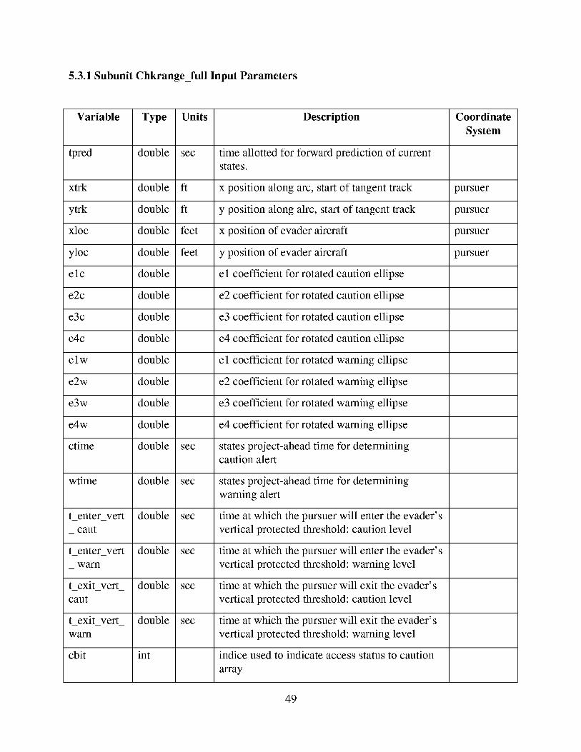
5.3.1 Subunit Chkrange_full Input Parameters
Variable Type
tpred double
xtrk double
ytrk double
xloc double
yloc double
elc double
e2c double
e3c double
e4c double
elw double
e2w double
e3w double
e4w double
ctime double
wtime double
tenter vert double
_ cant
tenter vert double
_ warn
t_exit very double
cant
t_exit very double
warn
cbit int
Units
sec
ft
ft
feet
feet
sec
sec
sec
sec
sec
sec
Description Coordinate
System
time allotted for forward prediction of current
states.
x position along arc, start of tangent track pursuer
y position along alrc, start of tangent track pursuer
x position of evader aircraft pursuer
y position of evader aircraft pursuer
el coefficient for rotated caution ellipse
e2 coefficient for rotated caution ellipse
e3 coefficient for rotated caution ellipse
e4 coefficient for rotated caution ellipse
el coefficient for rotated warning ellipse
e2 coefficient for rotated warning ellipse
e3 coefficient for rotated warning ellipse
e4 coefficient for rotated warning ellipse
states project-ahead time for determiningcaution alert
states project-ahead time for determining
warning alert
time at which the pursuer will enter the evader's
vertical protected threshold: caution level
time at which the pursuer will enter the evader's
vertical protected threshold: warning level
time at which the pursuer will exit the evader's
vertical protected threshold: caution level
time at which the pursuer will exit the evader's
vertical protected threshold: warning level
indice used to indicate access status to caution
array
49
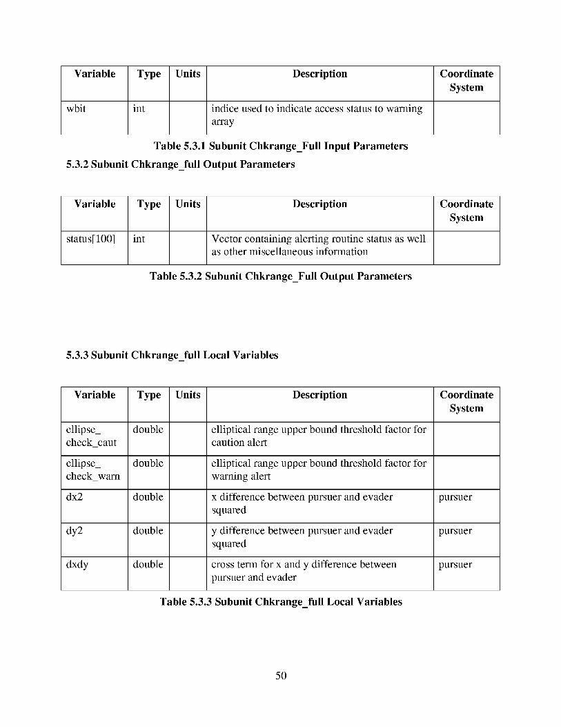
Variable
wbit
Type Units Description
int indice used to indicate access status to warning
array
Coordinate
System
Table 5.3.1 Subunit Chkrange_Full Input Parameters
5.3.2 Subunit Chkrange_full Output Parameters
Variable
status[lO0]
Type Units Description
int Vector containing alerting routine status as well
as other miscellaneous information
Coordinate
System
Table 5.3.2 Subunit Chkrange_Full Output Parameters
5.3.3 Subunit Chkrange_full Local Variables
Variable
ellipse_
check_cant
ellipse_
check_warn
dx2
dy2
dxdy
Type Units Description
double
double
double
double
double
elliptical range upper bound threshold factor for
caution alert
elliptical range upper bound threshold factor for
warning alert
x difference between pursuer and evader
squared
y difference between pursuer and evader
squared
cross term for x and y difference between
pursuer and evader
Coordinate
System
pursuer
pursuer
pursuer
Table 5.3.3 Subunit Chkrange_full Local Variables
50
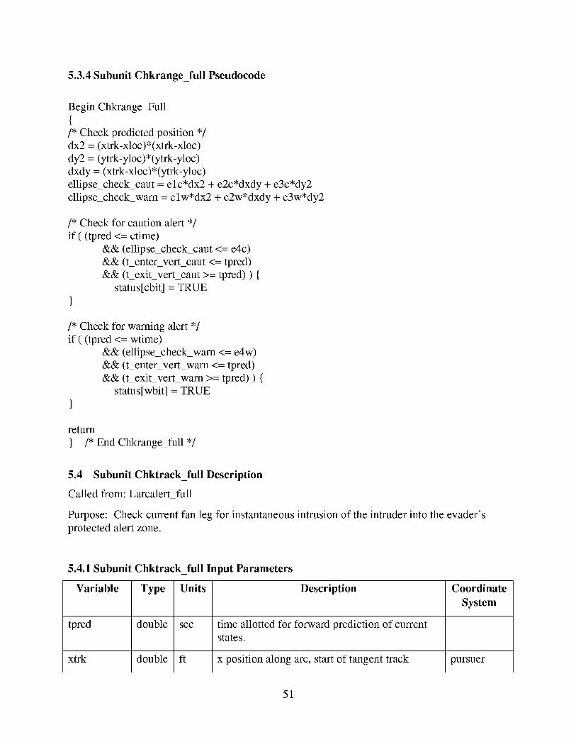
5.3.4 Subunit Chkrange_full Pseudocode
Begin Chkrange_Full
{/* Check predicted position */
dx2 = (xtrk-xloc)*(xtrk-xloc)
dy2 = (ytrk-yloc)*(ytrk-yloc)
dxdy = (xtrk-xloc)*(ytrk-yloc)
ellipse_check_cant = elc*dx2 + e2c*dxdy + e3c*dy2
ellipse_check_warn = elw*dx2 + e2w*dxdy + e3w*dy2
/* Check for caution alert */
if ( (tpred <= crime)
&& (ellipse_check_cant <= eAc)
&& (t_enter vert_caut <= tpred)
&& (t_exitverycaut >= tpred) ) {
status[cbit] = TRUE
}
/* Check for warning alert */
if ( (tpred <= wtime)
&& (ellipse_check_warn <= eAw)
&& (t_enter vert_warn <= tpred)
&& (t_exitverywarn >= tpred) ) {
status[wbit] = TRUE
}
return
} /* End Chkrange_full */
5.4 Subunit Chktrack_full Description
Called from: Larcalert_full
Purpose: Check current fan leg for instantaneous intrusion of the intruder into the evader's
protected alert zone.
5.4.1 Subunit Chktrack_full Input Parameters
Type Units DescriptionVariable
sec
ft
tpred double
xtrk double
Coordinate
System
time allotted for forward prediction of currentstates.
x position along arc, start of tangent track pursuer
51
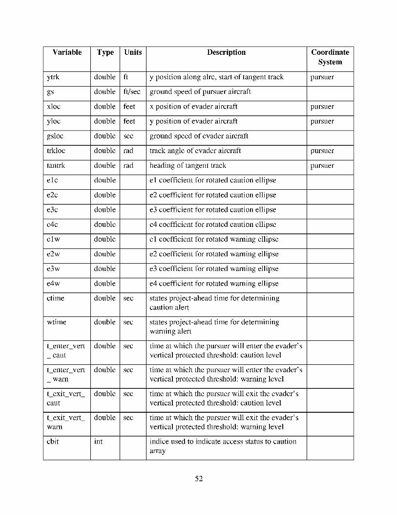
Variable Type
ytrk double
gs double
xloc double
yloc double
gsloc double
trkloc double
tantrk double
elc double
e2c double
e3c double
e4c double
elw double
e2w double
e3w double
e4w double
ctime double
wtime double
tenter vert double
_ cant
tenter vert double
_ warn
t_exit very double
cant
t_exit very double
warn
cbit int
Units
ft
ft/sec
feet
feet
sec
rad
rad
sec
sec
sec
sec
sec
sec
Description Coordinate
System
y position along alrc, start of tangent track pursuer
ground speed of pursuer aircraft
x position of evader aircraft pursuer
y position of evader aircraft pursuer
ground speed of evader aircraft
track angle of evader aircraft pursuer
heading of tangent track pursuer
el coefficient for rotated caution ellipse
e2 coefficient for rotated caution ellipse
e3 coefficient for rotated caution ellipse
e4 coefficient for rotated caution ellipse
el coefficient for rotated warning ellipse
e2 coefficient for rotated warning ellipse
e3 coefficient for rotated warning ellipse
e4 coefficient for rotated warning ellipse
states project-ahead time for determiningcaution alert
states project-ahead time for determining
warning alert
time at which the pursuer will enter the evader's
vertical protected threshold: caution level
time at which the pursuer will enter the evader's
vertical protected threshold: warning level
time at which the pursuer will exit the evader's
vertical protected threshold: caution level
time at which the pursuer will exit the evader's
vertical protected threshold: warning level
indice used to indicate access status to caution
array
52
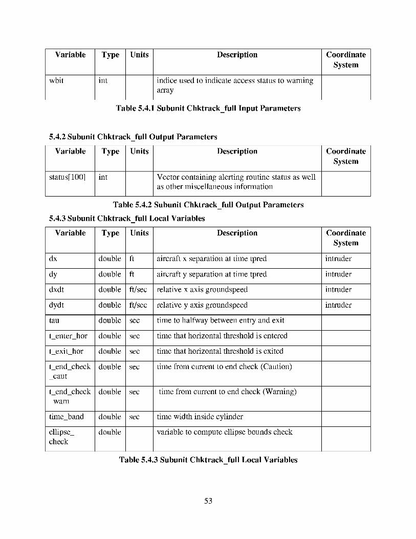
Variable
wbit
Type
int
Units Description
indice used to indicate access status to warning
array
Coordinate
System
Table 5.4.1 Subunit Chktrack_full Input Parameters
5.4.2 Subunit Chktrack_full Output Parameters
Type Units DescriptionVariable
status[lO0] int Vector containing alerting routine status as well
as other miscellaneous information
Table 5.4.2 Subunit Chktrack_full Output Parameters
5.4.3 Subunit Chktrack full Local Variables
Units
ft
ft
ft/sec
ft/sec
sec
sec
sec
sec
sec
Variable Type
dx double
dy double
dxdt double
dydt double
tan double
tenter hot double
texit hot double
tend_check double
_cant
tend_check double
_warn
time_band double
ellipse_ doublecheck
sec
Coordinate
System
Description Coordinate
System
aircraft x separation at time tpred intruder
aircraft y separation at time tpred intruder
relative x axis groundspeed intruder
relative y axis groundspeed intruder
time to halfway between entry and exit
time that horizontal threshold is entered
time that horizontal threshold is exited
time from current to end check (Caution)
time from current to end check (Warning)
time width inside cylinder
variable to compute ellipse bounds check
Table 5.4.3 Subunit Chktrack full Local Variables
53
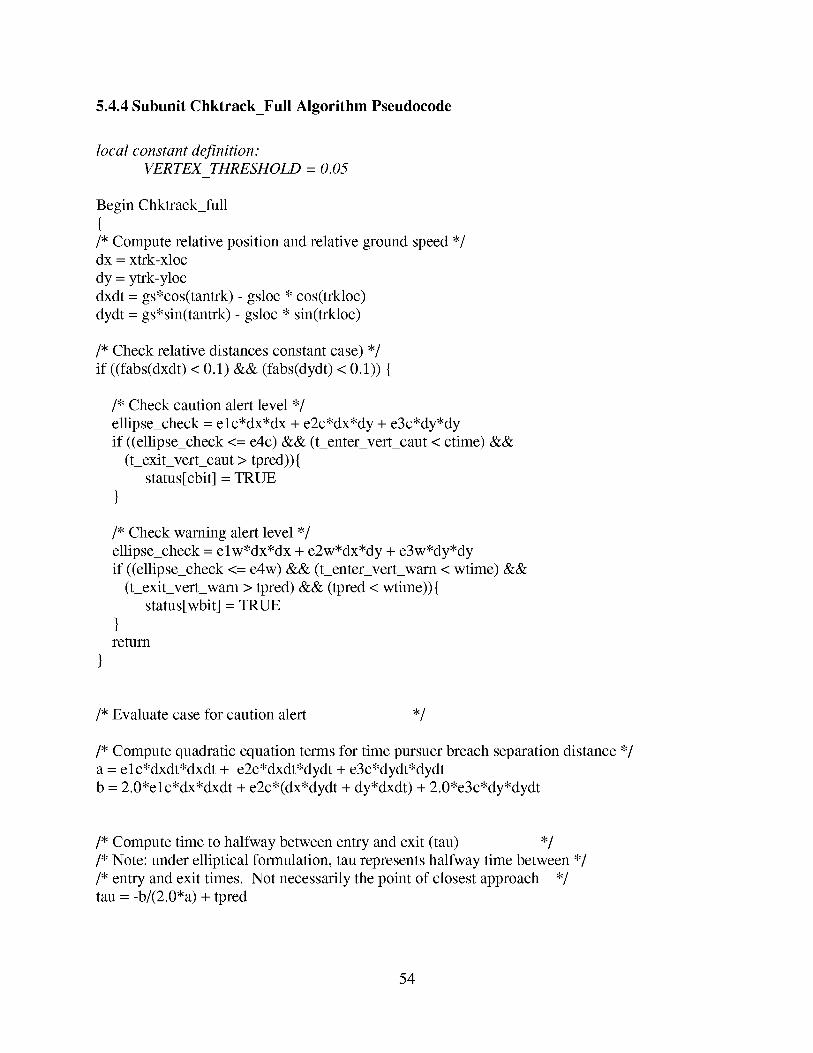
5.4.4 Subunit Chktrack_Full Algorithm Pseudocode
local constant definition."
VERTEX THRESHOLD = 0.05
Begin Chktrack_full
{/* Compute relative position and relative ground speed */dx = xtrk-xloc
dy = ytrk-yloc
dxdt = gs*cos(tantrk) - gsloc * cos(trkloc)
dydt = gs*sin(tantrk) - gsloc * sin(trkloc)
/* Check relative distances constant case) */
if ((fabs(dxdt) < 0.1) && (fabs(dydt) < 0.1)) {
/* Check caution alert level */
ellipse_check = elc*dx*dx + e2c*dx*dy + e3c*dy*dy
if ((ellipse_check <= eric) && (tenter vert_caut < ctime) &&
(texiyverycaut > tpred)){
status[cbit] = TRUE
}
/* Check warning alert level */
ellipse_check = elw*dx*dx + e2w*dx*dy + e3w*dy*dy
if ((ellipse_check <= e4w) && (tenter_verywarn < wtime) &&
(t_exit vert_warn > tpred) && (tpred < wtime)){
status[wbit] = TRUE
}return
/* Evaluate case for caution alert ,/
/* Compute quadratic equation terms for time pursuer breach separation distance */
a = elc*dxdt*dxdt + e2c*dxdt*dydt + e3c*dydt*dydt
b = 2.0*elc*dx*dxdt + e2c*(dx*dydt + dy*dxdt) + 2.0*e3c*dy*dydt
/* Compute time to halfway between entry and exit (tan) */
/* Note: under elliptical formulation, tan represents halfway time between */
/* entry and exit times. Not necessarily the point of closest approach */
tan = -b/(2.0*a) + tpred
54
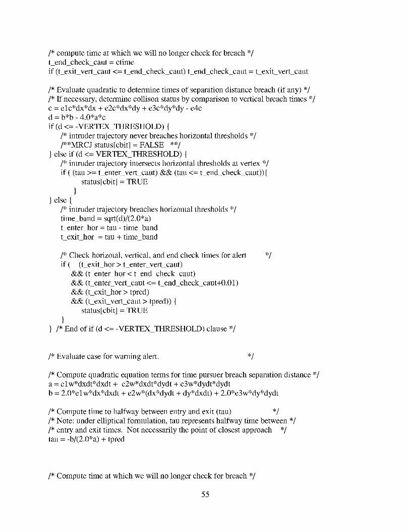
/* compute time at which we will no longer check for breach */
tend_check_cant =ctime
if (t_exit_vert_caut <= t_end_check_cant) t_end_check_cant = t_exit_vert_caut
/* Evaluate quadratic to determine times of separation distance breach (if any) */
/* If necessary, determine collison status by comparison to vertical breach times */
c = elc*dx*dx + e2c*dx*dy + e3c*dy*dy - e4cd = b*b - 4.0*a*c
if (d <= -VERTEX THRESHOLD) {
/* intruder trajectory never breaches horizontal thresholds */
/**MRCJ status[cbit] = FALSE **/
} else if (d <= VERTEX THRESHOLD) {
/* intruder trajectory intersects horizontal thresholds at vertex */
if ( (tan >= t_enter vert_caut) && (tan <= t_end_check_cant)){
status[cbit] = TRUE
}} else {
/* intruder trajectory breaches horizontal thresholds */
time_band = sqrt(d)/(2.0*a)t_enter hor = tan - time_band
t_exit hor = tan + time_band
/* Check horizotal, vertical, and end check times for alert
if ( (t_exit_hor > t_enter vert_caut)
&& (t_enter hor < tend_check_cant)
&& (t_enter vert_caut <= t_end_check_caut+0.01)
&& (texiyhor > tpred)
&& (texiyverycaut > tpred)) {
status[cbit] = TRUE
/* End of if (d <= -VERTEX THRESHOLD) clause */
,/
/* Evaluate case for warning alert. ,/
/* Compute quadratic equation terms for time pursuer breach separation distance */
a = elw*dxdt*dxdt + e2w*dxdt*dydt + e3w*dydt*dydt
b = 2.0*elw*dx*dxdt + e2w*(dx*dydt + dy*dxdt) + 2.0*e3w*dy*dydt
/* Compute time to halfway between entry and exit (tan) */
/* Note: under elliptical formulation, tan represents halfway time between */
/* entry and exit times. Not necessarily the point of closest approach */
tan = -b/(2.0*a) + tpred
/* Compute time at which we will no longer check for breach */
55
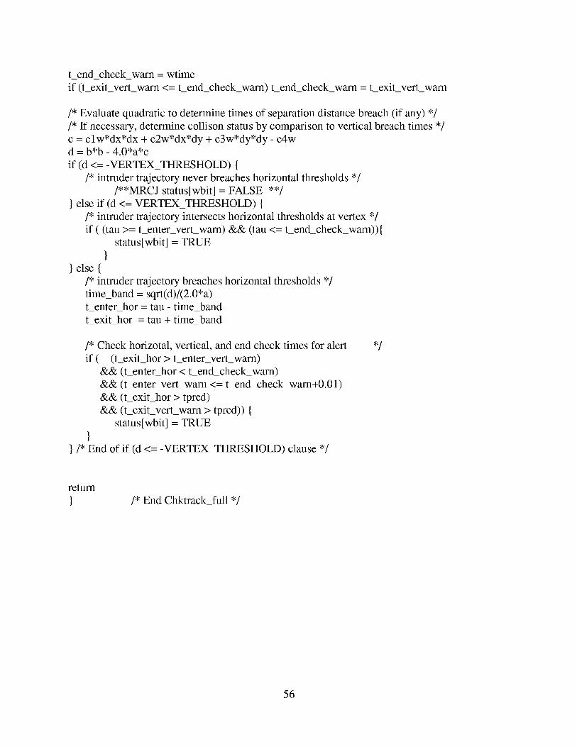
tend_check_warn= wtimeif (texiyverywarn <= tend_check_warn)tend_check_warn= texit_vert_warn
/* Evaluate quadratic to determine times of separation distance breach (if any) */
/* If necessary, determine collison status by comparison to vertical breach times */
c = elw*dx*dx + e2w*dx*dy + e3w*dy*dy - e4wd = b*b - 4.0*a*c
if (d <= -VERTEX THRESHOLD) {
/* intruder trajectory never breaches horizontal thresholds */
/**MRCJ status[wbit] = FALSE **/
} else if (d <= VERTEX THRESHOLD) {
/* intruder trajectory intersects horizontal thresholds at vertex */
if ( (tan >= t_enter vert_warn) && (tan <= t_end_check_warn)){
status[wbit] = TRUE
}} else {
/* intruder trajectory breaches horizontal thresholds */
time_band = sqrt(d)/(2.0*a)
t_enter hor = tan - time_band
t_exit hor = tan + time_band
/* Check horizotal, vertical, and end check times for alert
if ( (texiyhor > t_enter vert_warn)
&& (tenter hor < tend_check_warn)
&& (t_enter vert_warn <= t_end_check_warn+0.01)
&& (texiyhor > tpred)
&& (texiyverywarn > tpred)) {
status[wbit] = TRUE
}}/* End of if (d <= -VERTEX_THRESHOLD) clause */
,/
return
/* End Chktrack_full */
56
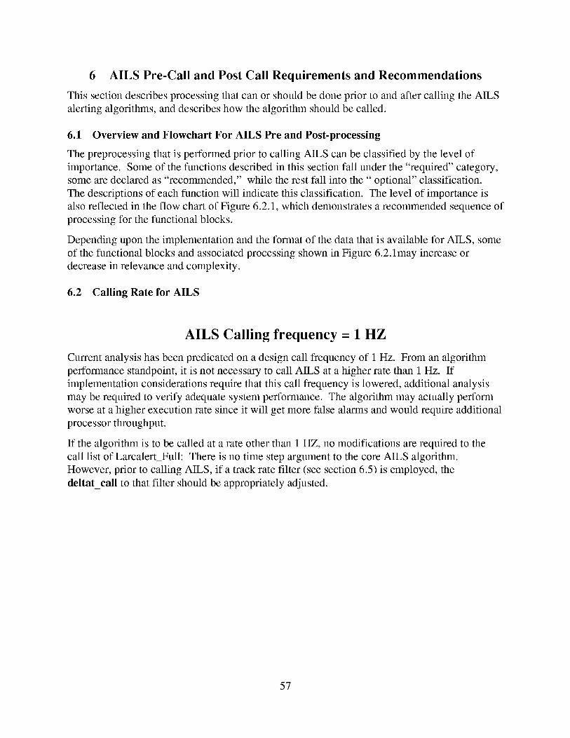
6 AILS Pre-Call and Post Call Requirements and Recommendations
This sectiondescribesprocessingthatcanor shouldbedoneprior to andaftercalling theAILSalertingalgorithms,anddescribeshow the algorithmshouldbecalled.
6.1 Overview and Flowchart For AILS Pre and Post-processing
The preprocessing that is performed prior to calling AILS can be classified by the level of
importance. Some of the functions described in this section fall under the "required" category,
some are declared as "recommended," while the rest fall into the" optional" classification.
The descriptions of each function will indicate this classification. The level of importance is
also reflected in the flow chart of Figure 6.2.1, which demonstrates a recommended sequence of
processing for the functional blocks.
Depending upon the implementation and the format of the data that is available for AILS, some
of the functional blocks and associated processing shown in Figure 6.2. lmay increase or
decrease in relevance and complexity.
6.2 Calling Rate for AILS
AILS Calling frequency = 1 HZ
Current analysis has been predicated on a design call frequency of 1 Hz. From an algorithm
performance standpoint, it is not necessary to call AILS at a higher rate than 1 Hz. If
implementation considerations require that this call frequency is lowered, additional analysis
may be required to verify adequate system performance. The algorithm may actually perform
worse at a higher execution rate since it will get more false alarms and would require additional
processor throughput.
If the algorithm is to be called at a rate other than 1 HZ, no modifications are required to the
call list of Larcalert_Full: There is no time step argument to the core AILS algorithm.
However, prior to calling AILS, if a track rate filter (see section 6.5) is employed, the
deltat_call to that filter should be appropriately adjusted.
57
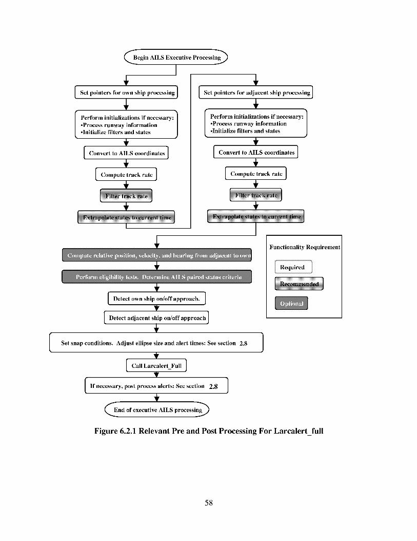
Begin AILS Executive Processing_
I
Set pointers for own ship processing }
"X
Perform initializations if necessary: /
•Process runway information J•Initialize filters and states
Convert to AILS coordinates ]
I_omp.totrackratoI
I
Set pointers for adjacent ship processing ]
Perform initializations if necessary:]•Process runway information•Initialize filters and states
Convert to AILS coordinates ]
÷I_omp.totrackratoI
÷
Detect own ship on/off approach. ]
V
Detect adjacent ship on/off approach ]
Set snap conditions. Adjust ellipse size and alert times: See section 2.8
Call LarcalertFull ]
If necessary, post process alerts: See section 2.8 ]
-End of executive AILS processing g_
Functionality Requirement
/i Required ]
Figure 6.2.1 Relevant Pre and Post Processing For Larcalert_full
58
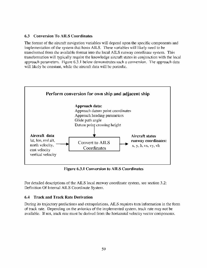
6.3 Conversion To AILS Coordinates
The format of the aircraft navigation variables will depend upon the specific components and
implementation of the system that hosts AILS. These variables will likely need to be
transformed from the available format into the local AILS runway coordinate system. This
transformation will typically require the knowledge aircraft states in conjunction with the local
approach parameters. Figure 6.3.1 below demonstrates such a conversion. The approach data
will likely be constant, while the aircraft data will be periodic.
Perform conversion for own ship and adjacent ship
Aircraft dat,t
lat, lon, msl alt, I
north velocity, _"Ieast velocity
vertical velocity
Approach data:
Approach datum point coordinates
Approach heading parameters
Glide path angle
Datum poin I crossing height
Convert to AILS
!Coordinates
Aircraft states
runway coordinates:
x, y, h, vx, vy, vh
Figure 6.3.1 Conversion to AILS Coordinates
For detailed descriptions of the AILS local runway coordinate system, see section 3.2:
Definition Of Internal AILS Coordinate System.
6.4 Track and Track Rate Derivation
During its trajectory predictions and extrapolations, AILS requires turn information in the form
of track rate. Depending on the avionics of the implemented system, track rate may not be
available. If not, track rate must be derived from the horizontal velocity vector components.
59
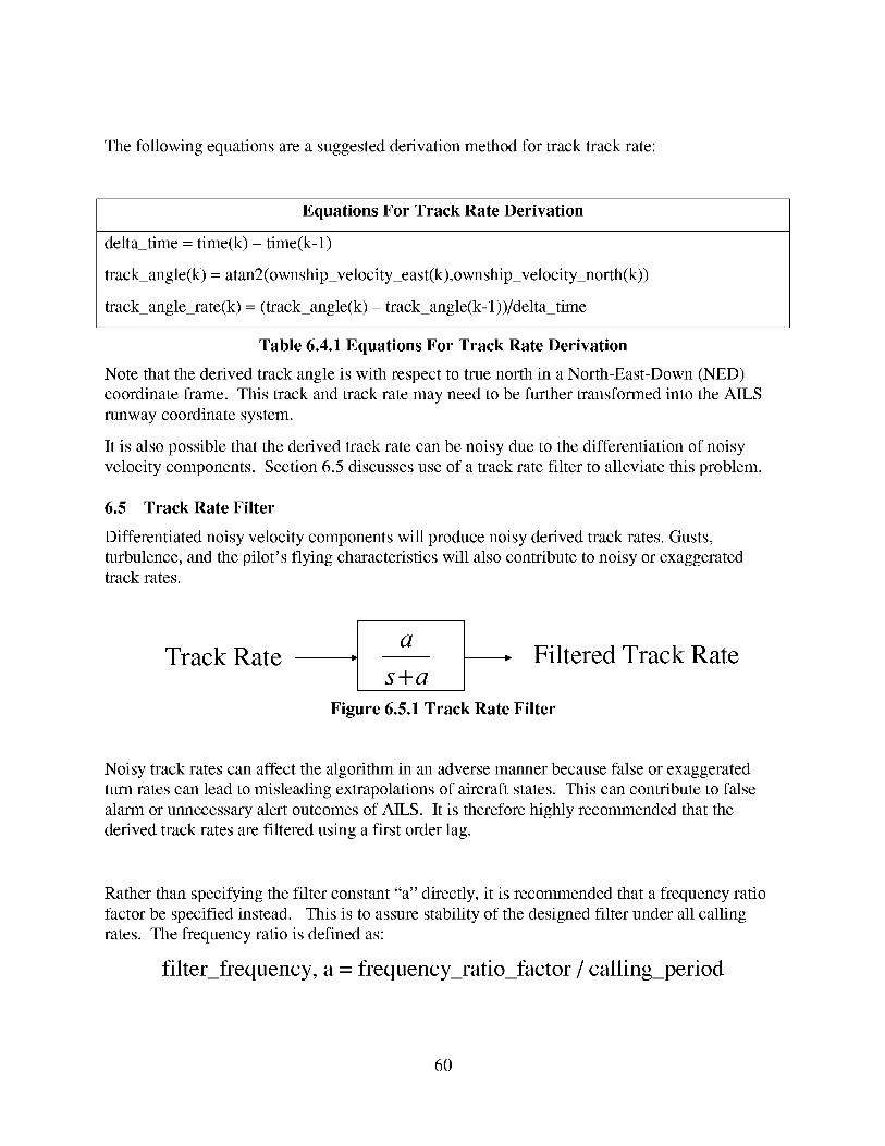
Thefollowing equationsarea suggestedderivationmethodfor tracktrack rate:
Equations For Track Rate Derivation
delta_time = time(k) - time(k-l)
track_angle(k) = atan2(ownship_velocity_east(k),ownship_velocity north(k))
track_angle_rate(k) = (track_angle(k) - track_angle(k- 1))/delta_time
Table 6.4.1 Equations For Track Rate Derivation
Note that the derived track angle is with respect to true north in a North-East-Down (NED)
coordinate frame. This track and track rate may need to be further transformed into the AILS
runway coordinate system.
It is also possible that the derived track rate can be noisy due to the differentiation of noisy
velocity components. Section 6.5 discusses use of a track rate filter to alleviate this problem.
6.5 Track Rate Filter
Differentiated noisy velocity components will produce noisy derived track rates. Gusts,
turbulence, and the pilot's flying characteristics will also contribute to noisy or exaggerated
track rates.
Track Ratea
s+aFiltered Track Rate
Figure 6.5.1 Track Rate Filter
Noisy track rates can affect the algorithm in an adverse manner because false or exaggerated
turn rates can lead to misleading extrapolations of aircraft states. This can contribute to false
alarm or unnecessary alert outcomes of AILS. It is therefore highly recommended that the
derived track rates are filtered using a first order lag.
Rather than specifying the filter constant "a" directly, it is recommended that a frequency ratio
factor be specified instead. This is to assure stability of the designed filter under all calling
rates. The frequency ratio is defined as:
filter_frequency, a = frequency_ratio_factor / calling_period
60
This first orderfilter wasdigitally implementedfor track-rateprocessingof thecurrentversionof AILS. Thefollowing parameterswereused:
calling period = 1 sec
frequency_ratio_factor =. 18
a =. 18 radians/sec
6.6 Data Integrity Test
Current analysis of the AILS system will allow engineers to assess the performance of AILS
under the implemented system configuration. Sensitivity analysis will show how system
performance metrics will vary with the data characteristics. Data integrity limits can be
deduced from such analysis and such limits should be applied in some form of data integrity
test.
An example would be that of the horizontal position error from the differential GPS system.
Sensitivity analysis can determine acceptable values of GPS system Horizontal Figure Of Merit
(HFOM) that allow the system to meet performance metrics. Integrity limits can then be
specified where failure to pass HFOM tests would preclude aircraft from being paired under
AILS protection. Such tests should be applied for all relevant navigation data used by the AILS
algorithm. The relevant data to be verified is listed:
• horizontal and vertical velocities
• horizontal and vertical positions
The analysis and tests should typically address the following attributes:
• uncorrelated errors (noise)
• first and second order errors of the states
• latency errors
• time tagging accuracy and time uncertainty errors
• parameter update rate
6.7 Extrapolate and Time Align Data
Aircraft position and velocity data that are available to the AILS algorithm prior to calling
AILS will likely have originated from two sources: the own ship and the adjacent ship.
Depending on the system and implementation, the data should have proper time tags associated
with the time of validity of the data.
Prior to calling AILS, and prior to comparing the data in a common frame of reference, the data
should be extrapolated and aligned to the current system time in the processor of the own ship.
61
This shouldbeperformedby using straightfirst orderextrapolationof velocity to thepositionstates:
x (extrapolated)= x (time_tagged)+ dx/dt * time_delta_from_taggedto current
y (extrapolated)= y (time_tagged)+ dy/dt * time_delta_from_taggedto current
h (extrapolated)= h (time_tagged)+ dh/dt* time_delta_from_taggedto current
wherethetime_delta_from_taggedto currentis thetime deltabetweenthetime-of-validity forthedataandthecurrenttime prior to calling AILS.
6.8 Compute Range, Range Rate, and Bearing to the Potential AILS Aircraft
Although not a requirement for output from AILS, it can be useful to compute values such as
the relative range, range rate, and bearing to aircraft that are emitting ADS-B in the vicinity of
the own aircraft. This information can be useful in determining if these aircraft are of potential
threat (see section 6.9) to each other. In the case where the aircraft are NOT mutual threats,
AILS would NOT be called which will prevent these values from being internally computed
within AILS. If the user relied on these parameters for system functions such as displays, it is
recommended that these values be computed outside of core AILS, regardless of whether or notAILS is called.
When the aircraft navigation states have been converted to local runway coordinates, the x, y,
and h positions will be relative to each ship's runway datum point. Transformations must be
performed to get the aircraft into a single coordinate system before the relative states can be
computed. Such coordinate transformations were described in detail in section 3.2: Definition
Of Internal AILS Coordinate System.
6.9 Determine AILS Aircraft Pairing
Recall that an AILS "pair" constitutes two aircraft that are in a simultaneous parallel approach
situation and are under protection of the AILS algorithm: AILS is invoked with these aircraft
as players in the own ship/adjacent ship scenario. Any particular aircraft on an approach at any
time can be paired with more than one other aircraft that is of potential threat.
Aircraft should become eligible to be paired only if they are established on final approach. The
AILS Path Length (APL) should be used as a factor to certify that an aircraft is close enough to
the appropriate runway in order to be declared as being on final approach. Recall that once the
inbound aircraft enter the APL, they may begin to lose the required 1000 ft vertical separation.
Once on final approach, it may still be impractical to pair all aircraft on the approach with all
the other aircraft on the adjacent parallel approach. Only aircraft that can potentially threaten
each other should be paired. It is therefore recommended that criteria should be established to
determine which aircraft to designate as AILS pairs. The criteria can be based on parameters
such as range and range-rate between the aircraft. Additionally, there should be smooth
transitions between the predominant overall separation assurance system (probably TCAS) and
62
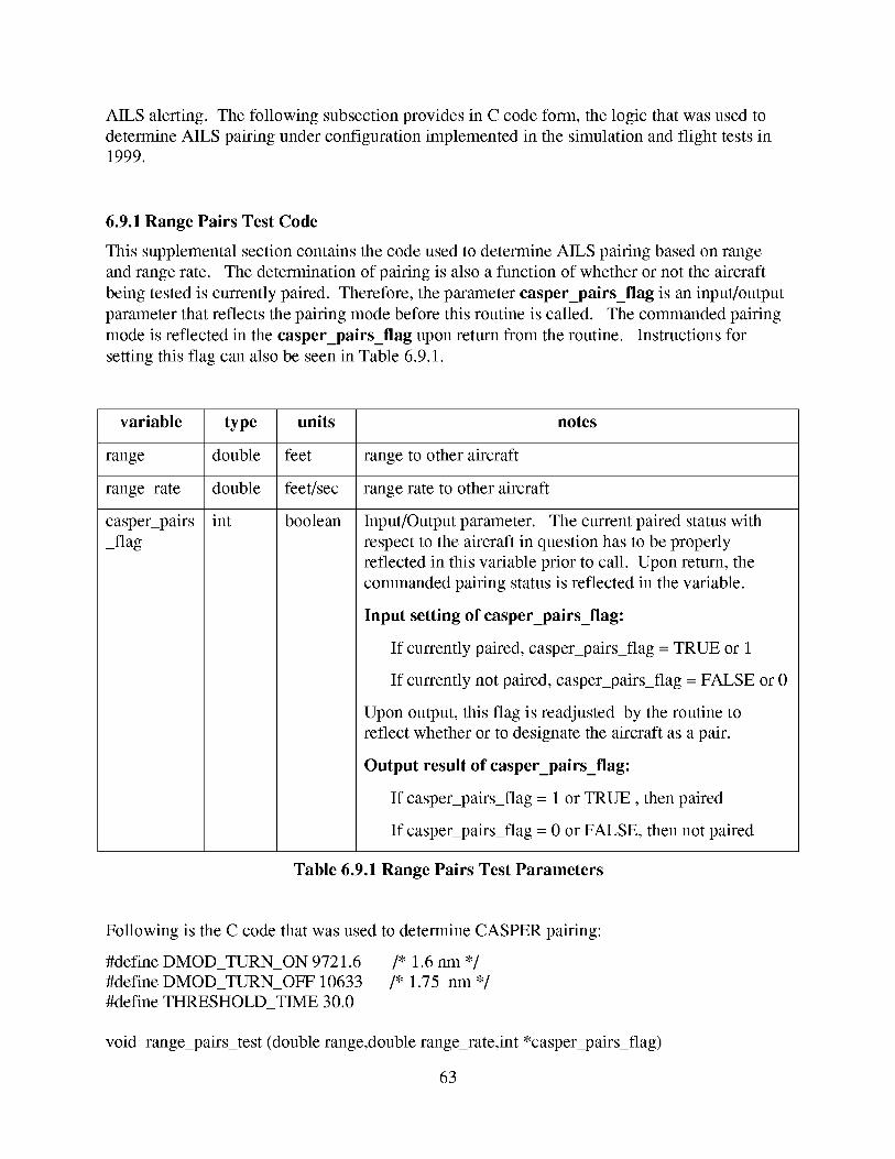
AILS alerting. Thefollowing subsectionprovidesin C codeform, the logic thatwasusedtodetermineAILS pairing underconfigurationimplementedin thesimulationandflight testsin1999.
6.9.1RangePairs Test Code
This supplemental section contains the code used to determine AILS pairing based on range
and range rate. The determination of pairing is also a function of whether or not the aircraft
being tested is currently paired. Therefore, the parameter casper_pairs_flag is an input/output
parameter that reflects the pairing mode before this routine is called. The commanded pairing
mode is reflected in the casper_pairs_flag upon return from the routine. Instructions for
setting this flag can also be seen in Table 6.9.1.
variable type units notes
range double feet range to other aircraft
range_rate double feet/sec range rate to other aircraft
int booleancasper pairs
_flag
Input/Output parameter. The current paired status with
respect to the aircraft in question has to be properly
reflected in this variable prior to call. Upon return, the
commanded pairing status is reflected in the variable.
Input setting of casper_pairs_flag:
If currently paired, casper pairs_flag = TRUE or 1
If currently not paired, casper pairs_flag = FALSE or 0
Upon output, this flag is readjusted by the routine to
reflect whether or to designate the aircraft as a pair.
Output result of casper_pairs_flag:
If casper_pairs_flag = 1 or TRUE, then paired
If casper_pairs_flag = 0 or FALSE, then not paired
Table 6.9.1 Range Pairs Test Parameters
Following is the C code that was used to determine CASPER pairing:
#define DMOD_TURN_ON 9721.6 /* 1.6 nm */
#define DMOD_TURN_OFF 10633 /* 1.75 nm */
#define THRESHOLD_TIME 30.0
void range_pairs_test (double range,double range_rate,int *casper pairs_flag)
63
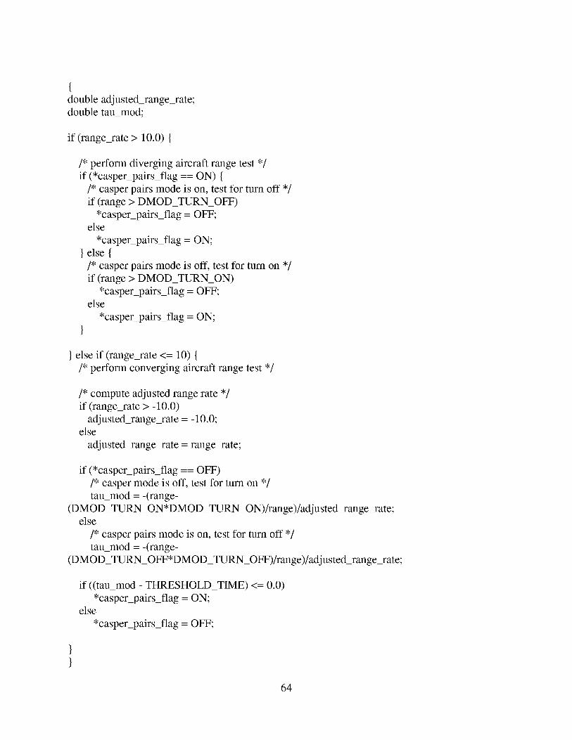
{double adjusted_range_rate;
double tau_mod;
if (range_rate > 10.0) {
/* perform diverging aircraft range test */
if (*casper pairs_flag == ON) {
/* casper pairs mode is on, test for turn off */
if (range > DMOD_TURN_OFF)
*casper_pairs_flag = OFF;else
*casper_pairs_flag = ON;
} else {
/* casper pairs mode is off, test for turn on */
if (range > DMOD_TURN_ON)
*casper pairs_flag = OFF;else
*casper pairs_flag = ON;
} else if (range_rate <= 10) {
/* perform converging aircraft range test */
/* compute adjusted range rate */
if (range_rate > - 10.0)
adju sted_range_rate = - 10.0;else
adjusted_range_rate = range_rate;
if (*casper_pairs_flag == OFF)
/* casper mode is off, test for turn on */
tau_mod = -(range-
(DMOD_TURN_ON*DMOD_TURN_ON)/range)/adju sted_range_rate;else
/* casper pairs mode is on, test for turn off */
tau_mod = -(range-
(DMOD_TURN_OFF*DMOD_TURN_OFF)/range)/adjusted_range_rate;
if ((tau_mod - THRESHOLD_TIME) <= 0.0)
*casper_pairs_flag = ON;else
*casper pairs_flag = OFF;
64

6.10 On-Approach/Off Approach Determination
AILS requires knowledge as to whether or not an aircraft is on or off of it's approach. The
following criteria is used as a guideline:
Aircraft declared OFF APPROACH if either of the following conditions are true:
1. More than 2 dots of vertical deviation.
2. More than 2 dots of lateral deviation OR more than 400 ft of lateral deviation to either side
of the approach path.
6.11 Ellipse and Time Parameter Adjustments
When one or both aircraft are off-approach, the alert parameters are adjusted since we know
which aircraft is to blame for collision threats, as discussed in 2.8: Ellipse Size Adjustments If
Aircraft is Off Approach.
6.12 Data Requirements Summary and Default Values
Table 5.1.1 in section 5.1.1 describes the input/output parameters to the Larcalert_full
algorithm. Table 6.12.1 shows a summary of the input variables to AILS. Some of the
variables to be provided to AILS are created by the preprocessing algorithms described in
sections 6.1- 6.11. Other variables are algorithm design parameters that are simply set. The
remainder of this section summarizes the requirements for all variables that are to be set.
6.12.1 AILS Parameter Input Summary Table
Variable Class Characteristics Variables Description
Reference
own aircraft states changes with each osxpos, osypos, osgs, ostrk, Table 5.1.1
call ostrkdot, oshpos
adjacent aircraft changes with each ajxpos, ajypos, ajgs, ajtrk, Table 5.1.1
states call ajtrkdot, ajh
own approach constant osglide,ostch Table 3.5.1
adjacent approach constant ajglide,ajtch Table 3.5.1
adjacent approach constant ajx_dp_offset, ajy_dp_offset, Table 5.1.3
relative to own ajh_dp_offset Table 5.1.1
alerting parameters
algorithm
parameters
constant, but
parameters can be
swapped if aircraft
off approach
constant
alvup, alvdown, aldste,
protected_esc
trkratedb, turntime, tstep
Table 3.5.1
Table 5.1.1
Table 5.1.1
65
Variable Class
snap flags
Characteristics
depends on if
aircraft on approach
Variables
os_snap_flag, aj_snap_flag
Description
Reference
Table 5.1.1
Table 6.12.1 AILS Parameter Input Summary
The following subsections describe the default settings and values for the AILS alerting and
algorithm parameters. These are values used under the current AILS simulation and flight test
configurations.
6.12.2 Default AILS Alerting Parameter Values
The following list is a summary of all the current default settings for AILS algorithm and
alerting parameters:
aldst_e(LEVEL 1 DOWNRANGE) = 5000 (ft)
aldst_e(LEVEL 1 CROSSRANGE)= 1800 (ft)
alvup(LEVEL_I) =1800 (ft)
alvdown(LEVEL_l) = 1800 (ft)
altime(LEVEL_l) -- 30 (sec)
aldst_e(LEVEL 2 DOWNRANGE) = 3500 (ft)
aldst_e(LEVEL 2 CROSSRANGE)= 1300 (ft)
alvup(LEVEL_2) =1300 (ft)
alvdown(LEVEL_2) = 1300 (ft)
altime(LEVEL_2) = 22 (sec)
aldst_e(LEVEL 3 DOWNRANGE) = 3400 (ft)
aldst_e(LEVEL 3 CROSSRANGE)= 1250 (ft)
alvup(LEVEL_3) =1250 (ft)
alvdown(LEVEL_3) = 1250(ft)
altime(LEVEL_3) = 21 (sec)
aldst_e(LEVEL 4 DOWNRANGE) = 2500 (ft)
66
aldst_e(LEVEL 4 CROSSRANGE)= 900(ft)
alvup(LEVEL_4)=900 (ft)
alvdown(LEVEL_4)= 900 (ft)
altime(LEVEL_4)= 16 (sec)
6.12.3 Default AILS Algorithm Parameters
tstep = 0.5 (sec)
turntime = 99 (sec)
trkratedb = 0.00024 (rad/sec)
Note that selecting turntime = 99 sec, is effectively disabling the turn limit feature.
2.11 (page 12).
See section
6.12.4 Default Protected Escape Zone Parameters
The following parameter values represent a defeated or disabled setting for the protected escape
zone. The key switch to disable the zone is the lateral distance set to a very large negative
number. This moves the protected zone far out in the direction opposite of the adjacently
paired aircraft.
protected_esc[LATERAL] = -999999 (ft)
protected_esc[ABOVE] = 0 (ft)
protected_esc[BELOW] = 0 (ft)
protected_esc[AHEAD] = 0 (ft)
protected_esc[BEHIND] = 0 (ft)
6.13 Status Array Interpretation
The AILS main routine returns the status vector which indicates the instantaneous alerting
status of AILS. The instantaneous status indicators are listed here:
status[LEVEL_l] = 0 or 1 : 1 indicates AILS level 1 alert TRUE, 0 indicates FALSE
status[LEVEL_2] = 0 or 1 : lindicates AILS level 2 alert TRUE, 0 indicates FALSE
status[LEVEL_3] = 0 or 1 : 1 indicates AILS level 3 alert TRUE, 0 indicates FALSE
status[LEVEL_4] = 0 or 1 : 1 indicates AILS level 4 alert TRUE, 0 indicates FALSE
67
status[PROTECTED_ESC_LEV_3]= 0 or 1 : 1 indicatesown shipin adjacentship'sprotectedescapezone,0 indicatesNO zoneviolation
status[PROTECTED_ESC_LEV_4]= 0 or 1 : 1 indicatesadjacentshipin own ship'sprotectedescapezone,0 indicatesNO zoneviolation
Recallthefollowing alert statusdefinitions:
Level 1 : Cautionfor own shipintruding at adjacentship
Level 2 : Cautionfor adjacentshipintruding at own ship
Level 3 : Warningfor own shipintruding at adjacentship
Level4 : Warningfor adjacentshipintruding at own ship
Note thatthestatusvectorreturnedrepresentsAILS operationbasedon instantaneouscurrentinformation. Thereis nomemory,persistence,or hysteresiseffecton thealert levels. It is up totheuserandcalling routinesto providesuchconditionsif desired.(Forexample,oncealevel 4alert is issued,thetop level operatorswill chooseto imposeapermanentlevel4 situation.Likewise, somehysteresiseffectmaybedesiredfor thealertlevels to preventon/off togglingstatusalongtheboundaryconditions).
6.14 Static vs Dynamic Memory Allocation Requirements For AILS
Internal AILS has NO static variables.
Some of the variables that are involved in the preprocessing prior to AILS involve filters and
states which will require some of those variables to be static.
68
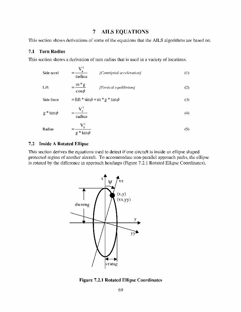
7 AILS EQUATIONS
This sectionshowsderivationsof someof theequationsthattheAILS algorithmsarebasedon.
7.1 Turn Radius
This section shows a derivation of turn radius that is used in a variety of locations.
2
VgSide accel - [Centripital acceleration] (1)
radius
m*gLift - [Vertical equilibrium] (2)
COS_
Side force = lift * sin_) = m * g * tan_) (3)
2
Vgg * tan_ - (4)
radius
2
VgRadius - (5)
g * tan_)
7.2 Inside A Rotated Ellipse
This section derives the equations used to detect if one aircraft is inside an ellipse shaped
protected region of another aircraft. To accommodate non-parallel approach paths, the ellipse
is rotated by the difference in approach headings (Figure 7.2.1 Rotated Ellipse Coordinates).
dwnmg /
X
,Y)(xx,yy)
L Y_
,/crsmg
Figure 7.2.1 Rotated Ellipse Coordinates
69
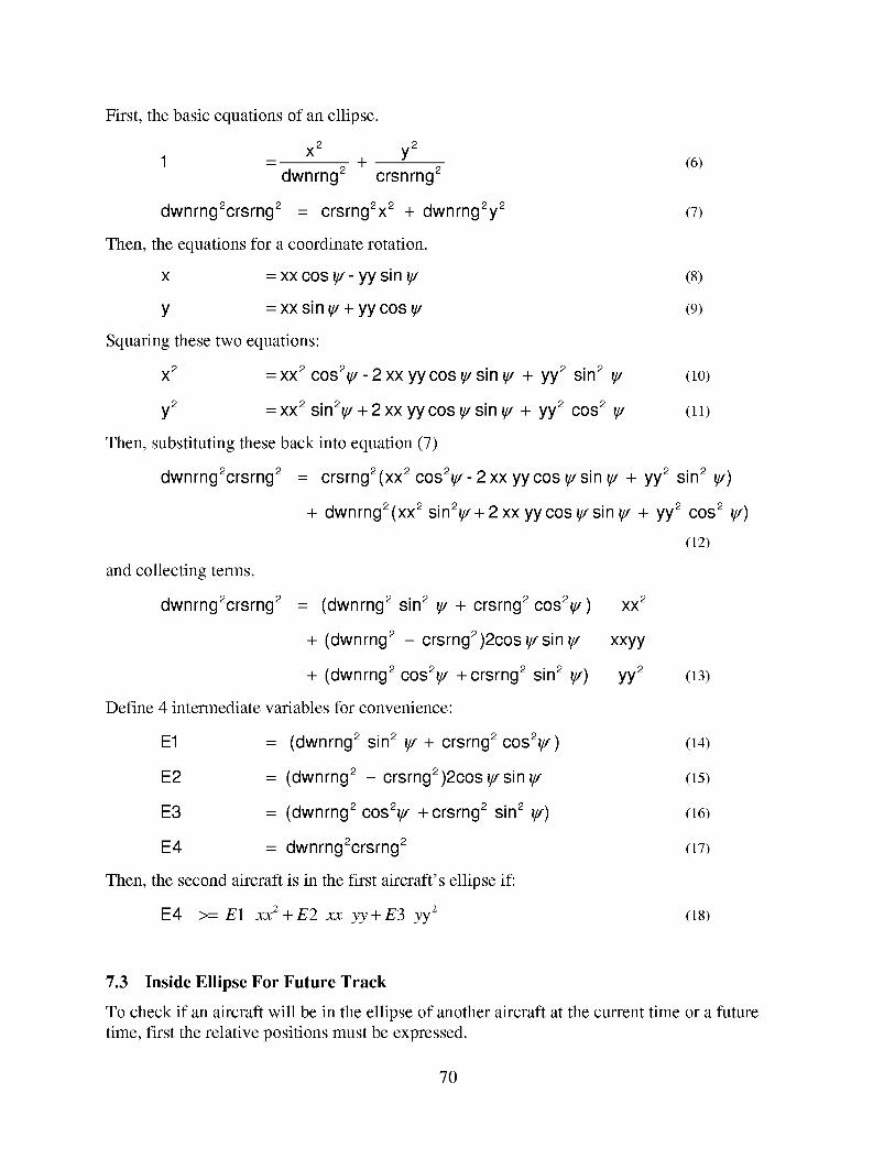
First, thebasicequationsof anellipse.
X 2 y2
1 - dwnrng 2 + crsnrng 2
dwnrng2crsrng 2 = crsrng2x 2 + dwnrng2y 2
Then, the equations for a coordinate rotation.
x = xx cos _ - yy sin _
y = xx sin _ + yy cos _
Squaring these two equations:
x 2 = xx 2 cos2_ - 2 xx yy cos _ sin _ + yy2 sin 2
y2 = xx 2 sin2_ + 2 xx yy cos _ sin _ + yy2 cos 2
Then, substituting these back into equation (7)
dwnrng2crsrng 2
(6)
(7)
(8)
(9)
(10)
(11)
= crsrng2(xx 2 cos2_ - 2 xx yycos _sin _ + yy2 sin 2 _)
+ dwnrng2(xx 2 sin2_+ 2 xx yycos _ sin _ + yy2 cos 2 _)
(12)
and collecting terms.
dwnrng2crsrng 2 = (dwnrng 2 sin 2 _ + crsrng 2 cos2_)
+ (dwnrng 2 - crsrng2)2cos _ sin
+ (dwnrng 2 cos2_ +crsrng 2 sin 2 _)
Define 4 intermediate variables for convenience:
E1 = (dwnrng 2 sin 2 _ + crsrng 2 cos2_) (14)
E2 = (dwnrng 2 - crsrng2)2cos _ sin _ (15)
E3 = (dwnrng 2 cos2_ +crsrng 2 sin 2 _) (16)
E4 = dwnrng2crsrng 2 (17)
Then, the second aircraft is in the first aircraft's ellipse if:
E4 >= E1 XX 2 + E2 xx yy + E3 yy2
XX 2
xxyy
yy2 (13)
(18)
7.3 Inside Ellipse For Future Track
To check if an aircraft will be in the ellipse of another aircraft at the current time or a future
time, first the relative positions must be expressed.
70
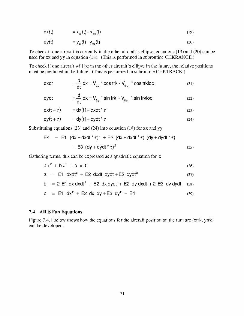
dx(t) = xaj(t ) - Xos(t ) (19)
dy(t) = yaj(t) - Yos(t) (20)
To check if one aircraft is currently in the other aircraft's ellipse, equations (19) and (20) can be
used for xx and yy in equation (18). (This is performed in subroutine CHKRANGE.)
To check if one aircraft will be in the other aircraft's ellipse in the future, the relative positions
must be predicted in the future. (This is performed in subroutine CHKTRACK.)
_ d dx * cos trk * trkloc (21)dxdt - d_- = vgaj - vg°° cos
_ d dx * sin trk * sin trkloc (22)dydt - d_- = Vgaj - Vgoo
dx(t + r) = dx(t)+ dxdt* r (23)
dy(t + r) = dy(t)+ dydt* r (24)
Substituting equations (23) and (24) into equation (18) for xx and yy:
E4 = E1 (dx+dxdt*r) 2 + E2 (dx+dxdt*r) (dy+dydt*r)
+ E3 (dy + dydt * z')2 (25)
Gathering terms, this can be expressed as a quadratic equation for _.
a ,./.2 -1-b ,./.2 -1-C ---- 0 (26)
a = E1 dxdt 2 + E2 dxdt dydt+E3 dydt 2 (27)
b = 2 E1 dxdxdt 2 + E2 dxdydt + E2 dydxdt +2 E3 dydydt (2s)
c = E1 dx 2 + E2 dx dy+E3 dy 2 - E4 (29)
7.4 AILS Fan Equations
Figure 7.4.1 below shows how the equations for the aircraft position on the turn arc (xtrk, ytrk)
can be developed.
71
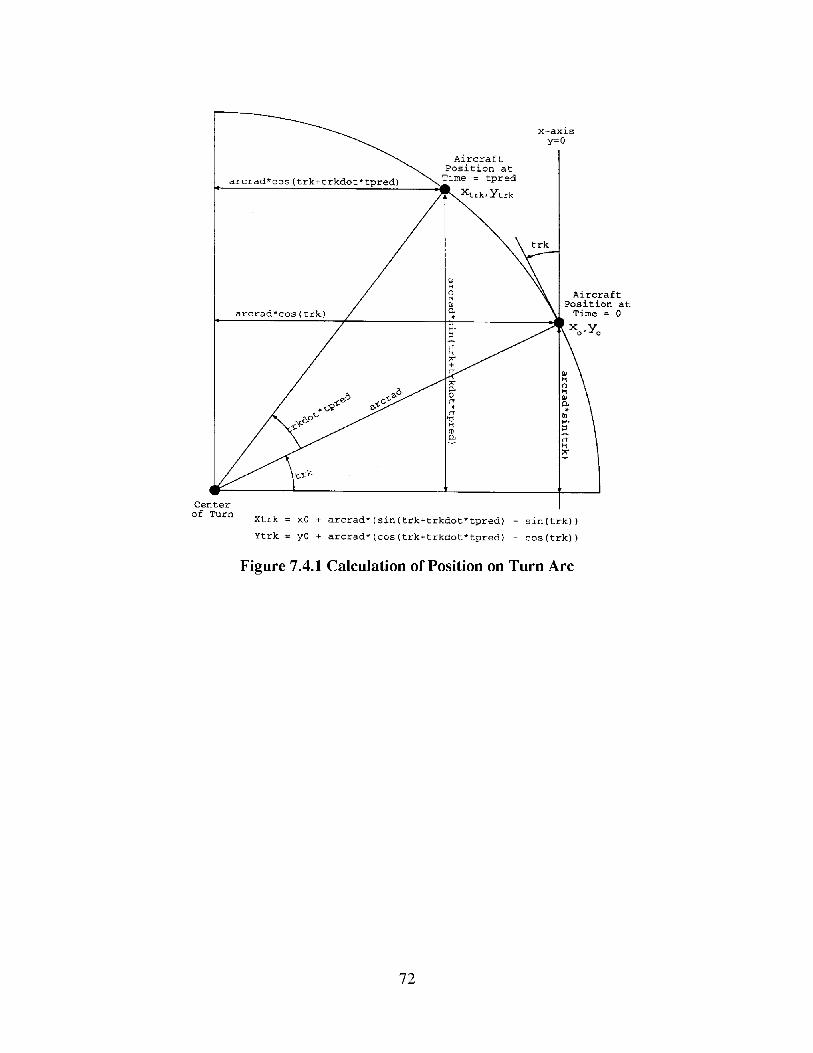
arcrad*cos(trk+trkdot*tpred)
arcrad*cos(trk)
x-axis
y=0
Aircraft
Position at
Time = tpred
Center
of TurnXtrk = x0 + arcrad*(sin(trk+trkdot*tpred) - sin(trk)}
Ytrk = y0 + arcrad*(cos(trk+trkdot*tpred) - cos(trk))
Figure 7.4.1 Calculation of Position on Turn Arc
Aircraft
Position at
Time = 0
X.yo
72
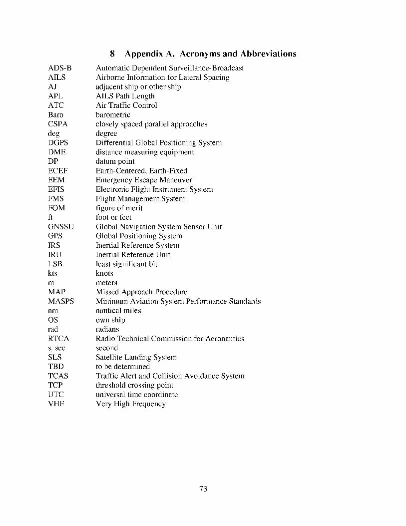
ADS-B
AILS
AJ
APL
ATC
Baro
CSPA
degDGPS
DME
DP
ECEF
EEM
EFIS
FMS
FOM
ft
GNSSU
GPS
IRS
IRU
LSB
kts
m
MAP
MASPS
nlTl
OS
rad
RTCA
S, sec
SLS
TBD
TCAS
TCP
UTC
VHF
8 AppendixA. Acronyms and Abbreviations
Automatic Dependent Surveillance-Broadcast
Airborne Information for Lateral Spacing
adjacent ship or other ship
AILS Path LengthAir Traffic Control
barometric
closely spaced parallel approaches
degree
Differential Global Positioning System
distance measuring equipment
datum point
Earth-Centered, Earth-Fixed
Emergency Escape Maneuver
Electronic Flight Instrument System
Flight Management System
figure of meritfoot or feet
Global Navigation System Sensor Unit
Global Positioning System
Inertial Reference SystemInertial Reference Unit
least significant bitknots
meters
Missed Approach Procedure
Minimum Aviation System Performance Standardsnautical miles
own shipradians
Radio Technical Commission for Aeronautics
second
Satellite Landing Systemto be determined
Traffic Alert and Collision Avoidance System
threshold crossing point
universal time coordinate
Very High Frequency
73
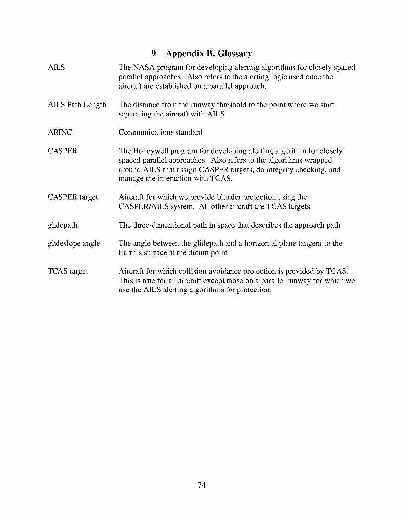
AILS
AILS PathLength
ARINC
CASPER
CASPERtarget
glidepath
glideslopeangle
TCAS target
9 AppendixB. Glossary
The NASA program for developing alerting algorithms for closely spaced
parallel approaches. Also refers to the alerting logic used once the
aircraft are established on a parallel approach.
The distance from the runway threshold to the point where we start
separating the aircraft with AILS
Communications standard
The Honeywell program for developing alerting algorithm for closely
spaced parallel approaches. Also refers to the algorithms wrapped
around AILS that assign CASPER targets, do integrity checking, and
manage the interaction with TCAS.
Aircraft for which we provide blunder protection using the
CASPER/AILS system. All other aircraft are TCAS targets
The three-dimensional path in space that describes the approach path
The angle between the glidepath and a horizontal plane tangent to the
Earth's surface at the datum point
Aircraft for which collision avoidance protection is provided by TCAS.
This is true for all aircraft except those on a parallel runway for which we
use the AILS alerting algorithms for protection.
74
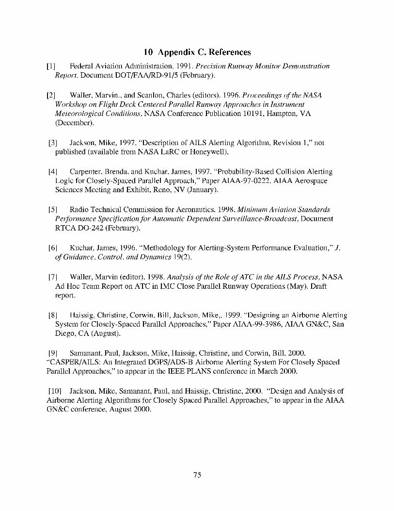
10 Appendix C. References
[1] Federal Aviation Administration. 1991. Precision Runway Monitor Demonstration
Report. Document DOT/FAA/RD-91/5 (February).
[2] Waller, Marvin., and Scanlon, Charles (editors). 1996. Proceedings of the NASA
Workshop on Flight Deck Centered Parallel Runway Approaches in Instrument
Meteorological Conditions, NASA Conference Publication 10191, Hampton, VA
(December).
[3] Jackson, Mike, 1997. "Description of AILS Alerting Algorithm, Revision 1," not
published (available from NASA LaRC or Honeywell).
[4] Carpenter, Brenda, and Kuchar, James, 1997. "Probability-Based Collision Alerting
Logic for Closely-Spaced Parallel Approach," Paper AIAA-97-0222. AIAA Aerospace
Sciences Meeting and Exhibit, Reno, NV (January).
[5] Radio Technical Commission for Aeronautics. 1998. Minimum Aviation Standards
Performance Specification for Automatic Dependent Surveillance-Broadcast, Document
RTCA DO-242 (February).
[6] Kuchar, James, 1996. "Methodology for Alerting-System Performance Evaluation," J.
of Guidance, Control, and Dynamics 19(2).
[7] Waller, Marvin (editor). 1998. Analysis of the Role of ATC in the AILS Process, NASA
Ad Hoc Team Report on ATC in IMC Close Parallel Runway Operations (May). Draft
report.
[8] Haissig, Christine, Corwin, Bill, Jackson, Mike,. 1999. "Designing an Airborne Alerting
System for Closely-Spaced Parallel Approaches," Paper AIAA-99-3986, AIAA GN&C, San
Diego, CA (August).
[9] Samanant, Paul, Jackson, Mike, Haissig, Christine, and Corwin, Bill, 2000.
"CASPER/AILS: An Integrated DGPS/ADS-B Airborne Alerting System For Closely Spaced
Parallel Approaches," to appear in the IEEE PLANS conference in March 2000.
[10] Jackson, Mike, Samanant, Paul, and Haissig, Christine, 2000. "Design and Analysis of
Airborne Alerting Algorithms for Closely Spaced Parallel Approaches," to appear in the AIAA
GN&C conference, August 2000.
75
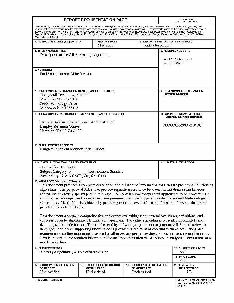
R E PORT D O C U M ENTATI O N PAGE Form ApprovedOMB No. 0704-0188
Public reporting burden for this collection of information is estimated to average 1 hour per response, including the time for reviewing instructions, searching existing datasources, gathering and maintaining the data needed, and completing and reviewing the collection of information. Send comments regarding this burden estimate or any otheraspect of this collection of information, including suggestions for reducing this burden, to Washington Headquarters Services Directorate for Information Operations andReports, 1215 Jefferson Davis Highway, Suite 1204, Arlington, VA 22202-4302, and to the Office of Management and Budget, Paperwork Reduction Project (0704-0188),Washington, DC 20503.
1. AGENCY USE ONLY (Leave blank) 2. REPORT DATE 3. REPORT TYPE AND DATES COVERED
May 2000 Contractor Report
4. TITLE AND SUBTITLE
Description of the AILS Alerting Algorithm
6. AUTHOR(S)Paul Samanant and Mike Jackson
7. PERFORMING ORGANIZATION NAME(S) AND ADDRESS(ES)
Honeywell Technology CenterMail Stop MN 65-2810
3660 Technology DriveMinneapolis, MN 55418
9. SPONSORING/MONITORING AGENCY NAME(S) AND ADDRESS(ES)
National Aeronautics and Space Administration
Langley Research CenterHampton, VA 23681-2199
5. FUNDING NUMBERS
WU 576-02-11-17
PO L-10690
8. PERFORMING ORGANIZATION
REPORT NUMBER
10. SPONSORING/MONITORING
AGENCY REPORT NUMBER
NASA/CR-2000-210109
11. SUPPLEMENTARY NOTES
Langley Technical Monitor Terry Abbott
12a. DISTRIBUTION/AVAILABILITY STATEMENT
Unclassified-Unlimited
Subject Category 3 Distribution: StandardAvailability: NASA CASI (301) 621-0390
12b. DISTRIBUTION CODE
13. ABSTRACT (Maximum 200 words)
This document provides a complete description of the Airborne Information for Lateral Spacing (AILS) alerting
algorithms. The purpose of AILS is to provide separation assurance between aircraft during simultaneousapproaches to closely spaced parallel runways. AILS will allow independent approaches to be flown in such
situations where dependent approaches were previously required (typically under Instrument Meteorological
Conditions (IMC)). This is achieved by providing multiple levels of alerting for pairs of aircraft that are inparallel approach situations.
This document's scope is comprehensive and covers everything from general overviews, definitions, andconcepts down to algorithmic elements and equations. The entire algorithm is presented in complete and
detailed pseudo-code format. This can be used by software programmers to program AILS into a softwarelanguage. Additional supporting information is provided in the form of coordinate frame definitions, data
requirements, calling requirements as well as all necessary pre-processing and post-processing requirements.This is important and required information for the implementation of AILS into an analysis, a simulation, or a
real-time system
14. SUBJECT TERMS
Alerting Algorithms; AILS Software design
17. SECURITY CLASSIFICATION
OF REPORT
Unclassified
18. SECURITY CLASSIFICATION
OF THIS PAGE
Unclassified
19. SECURITY CLASSIFICATION
OF ABSTRACT
Unclassified
15. NUMBER OF PAGES
88
16. PRICE CODE
A05
20. LIMITATION
OF ABSTRACT
UL
NSN 7540-01-280-5500 Standard Form 298 (Rev. 2-89)
Prescribed by ANSIStd. Z-39-18298-102