Embed Size (px)
Citation preview

D 6400 E 04.2015
Stainless Steel Air Motors
from 20 W / 0.03 Hp up to 1.2 kW / 1.6 Hp
ADVANCED LINE
The ADVANCED LINE air motors are parti-
cularly suitable for use in the food industry,
medical technology, underwater applica-
tions and the chemical industry.
All airmotors are made from stainless steel
and can also be used without lubrication.
All external parts (housing and spindle)
of our ADVANCED LINE series are made
from high quality non corrosive steel.
Our air motors are also available in an
ATEX conform complete system with inte-
grated holding brakes.
In addition our modular principle enables
us to offer low cost customisations for your
specific application!
NEW MOTOR RANGEnon corrosive ATEX conform oil-free sealed
sterilisable compact insensitive to cleaning solvents
High torque motors made
from stainless steel:
Our ADVANCED LINE pneu-
matic motors are now availab-
le as high torque motors made
from stainless steel. The ideal
drive solution for e.g. agitators
and industrial mixers.
Screwdriving technology Automation Air motors Air tools
2
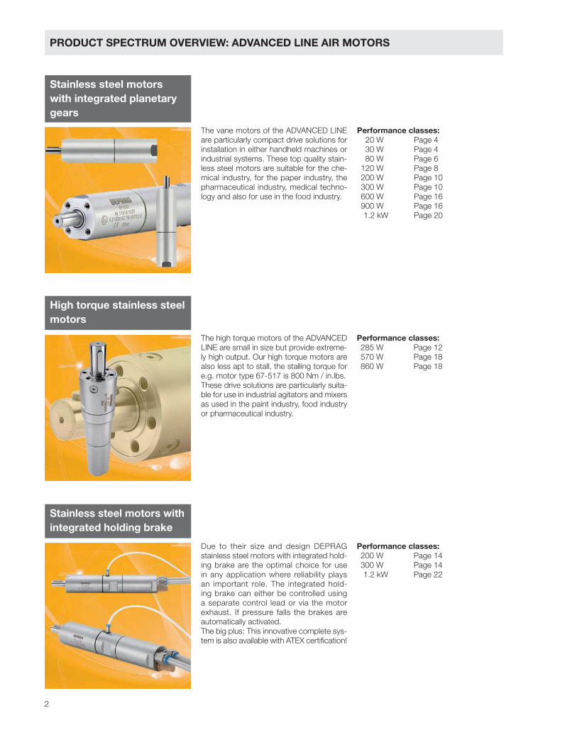
PRODUCT SPECTRUM OVERVIEW: ADVANCED LINE AIR MOTORS
Stainless steel motors
with integrated planetary
gears
High torque stainless steel
motors
Stainless steel motors with
integrated holding brake
The vane motors of the ADVANCED LINE
are particularly compact drive solutions for
installation in either handheld machines or
industrial systems. These top quality stain-
less steel motors are suitable for the che-
mical industry, for the paper industry, the
pharmaceutical industry, medical techno-
logy and also for use in the food industry.
Performance classes:
20 W Page 4
30 W Page 4
80 W Page 6
120 W Page 8
200 W Page 10
300 W Page 10
600 W Page 16
900 W Page 16
1.2 kW Page 20
Performance classes:
285 W Page 12
570 W Page 18
860 W Page 18
Performance classes:
200 W Page 14
300 W Page 14
1.2 kW Page 22
The high torque motors of the ADVANCED
LINE are small in size but provide extreme-
ly high output. Our high torque motors are
also less apt to stall, the stalling torque for
e.g. motor type 67-517 is 800 Nm / in.lbs.
These drive solutions are particularly suita-
ble for use in industrial agitators and mixers
as used in the paint industry, food industry
or pharmaceutical industry.
Due to their size and design DEPRAG
stainless steel motors with integrated hold-
ing brake are the optimal choice for use
in any application where reliability plays
an important role. The integrated hold-
ing brake can either be controlled using
a separate control lead or via the motor
exhaust. If pressure falls the brakes are
automatically activated.
The big plus: This innovative complete sys-
tem is also available with ATEX certification!

3
ADVANTAGES OF ADVANCED LINE AIR MOTORS
WIDE VARIETY AND
COMPREHENSIVE RANGE OF
ACCESSORIES
Our standard programme is distinguished
by its wide variety. All our stainless steel
motors are also available with threaded
spindle. Additionally due to our modular
principle we are able to offer numerous
variations to choose from. Do not hesitate
to contact us if you have a specific mount-
ing fixture request.
Large amount of in-house production, on-site salt bath heat treatment facility
Airmotor - gear box - valve: a stainless steel system for the paper industry,sealed stainless steel motors, high performance vanes
Performance testing facility, professional guidance from our engineers
Individual customisation at an attractive price
LONG LIFE-SPAN
A wide product range of stainless steel
motors, the use of DEPRAG high per-
formance vanes as well as a specific
surface coating on our materials all this
ensures your motor's long life-span.
SHORT DELIVERY TIMES
Due to our large amount of in-house
production we are able to deliver
quickly and flexibly at short notice,
even when dealing with smaller quan-
tities.
APPLICATION CONSULTANCY
Our application engineers will gladly
advise you in the selection of the most
suitable drive for your application. If
you would like to test or replace your
existing drive we can check it for you
in our innovative performance testing
facility.
4
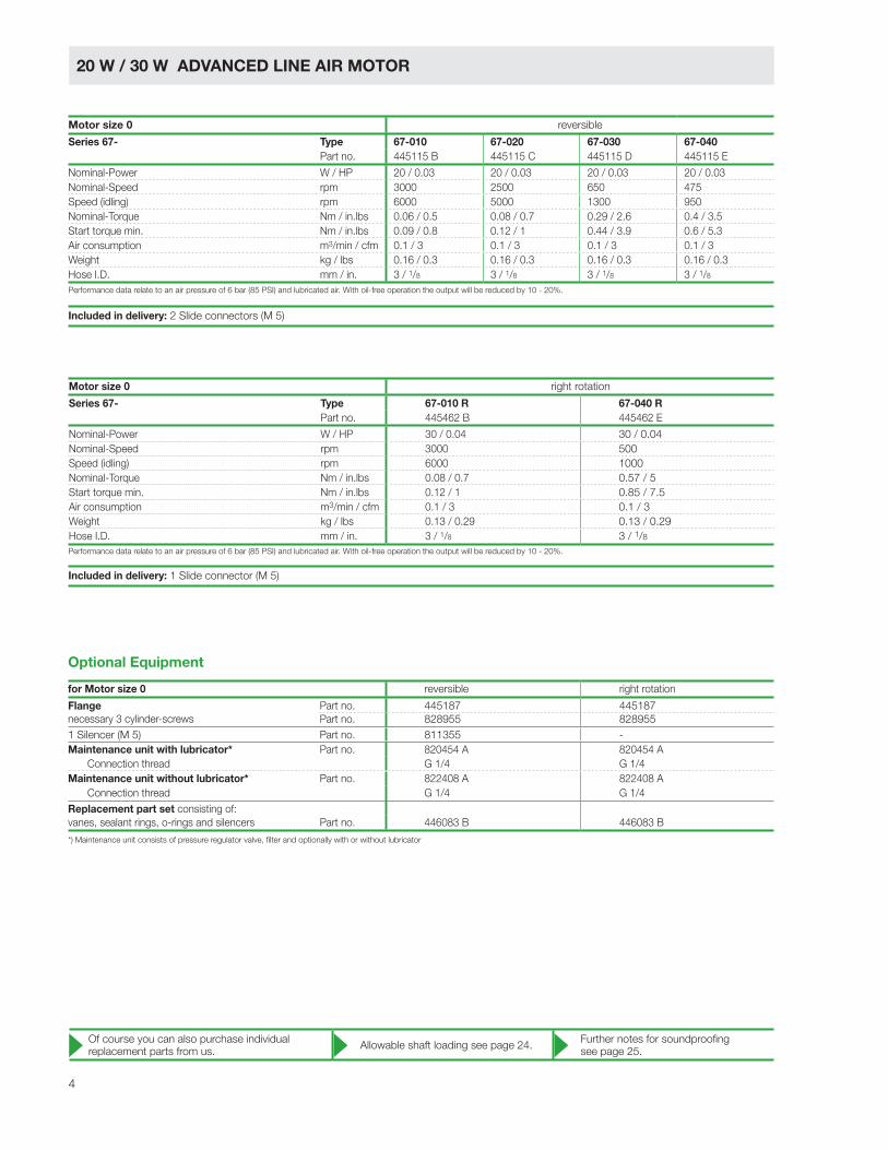
20 W / 30 W ADVANCED LINE AIR MOTOR
Performance data relate to an air pressure of 6 bar (85 PSI) and lubricated air. With oil-free operation the output will be reduced by 10 - 20%.
Performance data relate to an air pressure of 6 bar (85 PSI) and lubricated air. With oil-free operation the output will be reduced by 10 - 20%.
Motor size 0 reversible
Series 67- Type 67-010 67-020 67-030 67-040
Part no. 445115 B 445115 C 445115 D 445115 E
Nominal-Power W / HP 20 / 0.03 20 / 0.03 20 / 0.03 20 / 0.03
Nominal-Speed rpm 3000 2500 650 475
Speed (idling) rpm 6000 5000 1300 950
Nominal-Torque Nm / in.lbs 0.06 / 0.5 0.08 / 0.7 0.29 / 2.6 0.4 / 3.5
Start torque min. Nm / in.lbs 0.09 / 0.8 0.12 / 1 0.44 / 3.9 0.6 / 5.3
Air consumption m3/min / cfm 0.1 / 3 0.1 / 3 0.1 / 3 0.1 / 3
Weight kg / lbs 0.16 / 0.3 0.16 / 0.3 0.16 / 0.3 0.16 / 0.3
Hose I.D. mm / in. 3 / 1/8 3 / 1/8 3 / 1/8 3 / 1/8
Included in delivery: 2 Slide connectors (M 5)
Included in delivery: 1 Slide connector (M 5)
Of course you can also purchase individual
replacement parts from us.Allowable shaft loading see page 24.
Further notes for soundproofing
see page 25.
Motor size 0 right rotation
Series 67- Type 67-010 R 67-040 R
Part no. 445462 B 445462 E
Nominal-Power W / HP 30 / 0.04 30 / 0.04
Nominal-Speed rpm 3000 500
Speed (idling) rpm 6000 1000
Nominal-Torque Nm / in.lbs 0.08 / 0.7 0.57 / 5
Start torque min. Nm / in.lbs 0.12 / 1 0.85 / 7.5
Air consumption m3/min / cfm 0.1 / 3 0.1 / 3
Weight kg / lbs 0.13 / 0.29 0.13 / 0.29
Hose I.D. mm / in. 3 / 1/8 3 / 1/8
*) Maintenance unit consists of pressure regulator valve, filter and optionally with or without lubricator
for Motor size 0 reversible right rotation
Flange Part no. 445187 445187
necessary 3 cylinder-screws Part no. 828955 828955
1 Silencer (M 5) Part no. 811355 -
Maintenance unit with lubricator* Part no. 820454 A 820454 A
Connection thread G 1/4 G 1/4
Maintenance unit without lubricator* Part no. 822408 A 822408 A
Connection thread G 1/4 G 1/4
Replacement part set consisting of:
vanes, sealant rings, o-rings and silencers Part no. 446083 B 446083 B
Optional Equipment
5
ø 26
Exhaust air
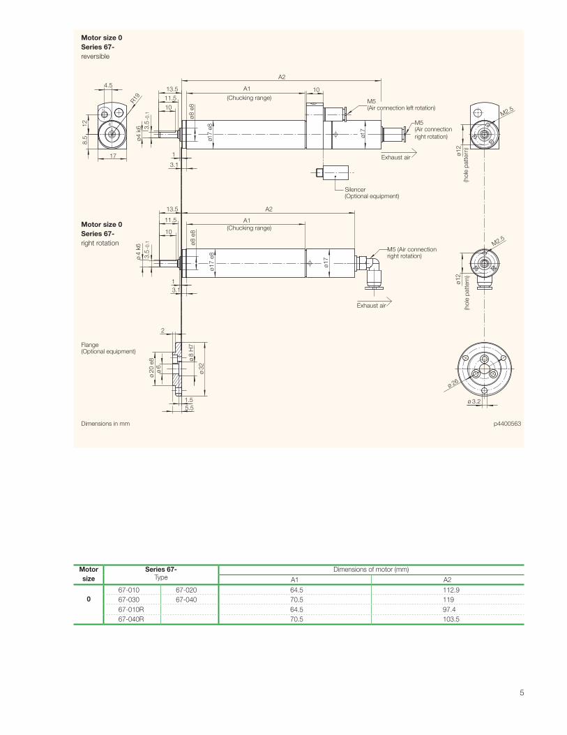
p4400563Dimensions in mm
Silencer(Optional equipment)
M5 (Air connection left rotation)
M5 (Air connection
right rotation)
M5 (Air connection right rotation)
R19
4.51
28
.5
17
3.5
-0.1
ø4
k6
10
11.5
13.5
1
3.1
A1
(Chucking range)
A2
ø8
e8
ø17
e8
ø17
M2.5
ø1
2
(ho
le p
att
ern
)(h
ole
patt
ern
)
10
11.5
13.5
3.5
-0.1
ø4
k6
1
3.1
ø8
e8
ø1
7 e
8
ø1
7
A2
A1
(Chucking range)
ø1
2
M2.5
ø2
0 e
8
ø6
ø8
H7
ø3
2
1.5
5.5ø 3.2
10
2
4
4
Flange(Optional equipment)
Exhaust air
Motor size 0
Series 67-
reversible
Motor size 0
Series 67-
right rotation
Motor
size
Series 67-
Type
Dimensions of motor (mm)
A1 A2
0
67-010 67-020 64.5 112.9
67-030 67-040 70.5 119
67-010R 64.5 97.4
67-040R 70.5 103.5

6
80 W ADVANCED LINE AIR MOTOR
*) Maintenance unit consists of pressure regulator valve, filter and optionally with or without lubricator
Performance data relate to an air pressure of 6 bar (85 PSI) and lubricated air. With oil-free operation the output will be reduced by 10 - 20%. *) max. admissible torque
Motor size 1 reversible
Series 67- Type 67-001 67-011 67-021 67-031 67-081
Part no. 445127 A 445127 B 445127 C 445127 D 445127 E
Nominal-Power W / HP 80 / 0.11 80 / 0.11 80 / 0.11 80 / 0.11 80 / 0.11
Nominal-Speed rpm 11000 3500 950 650 120
Speed (idling) rpm 22000 7000 1900 1300 240
Nominal-Torque Nm / in.lbs 0.06 / 0.5 0.22 / 1.9 0.8 / 7 1.2 / 11 2 / 17.7 *)
Start torque min. Nm / in.lbs 0.09 / 0.8 0.33 / 2.9 1.2 / 11 1.8 / 16 2 / 17.7 *)
Air consumption m3/min / cfm 0.23 / 8 0.23 / 8 0.23 / 8 0.23 / 8 0.23 / 8
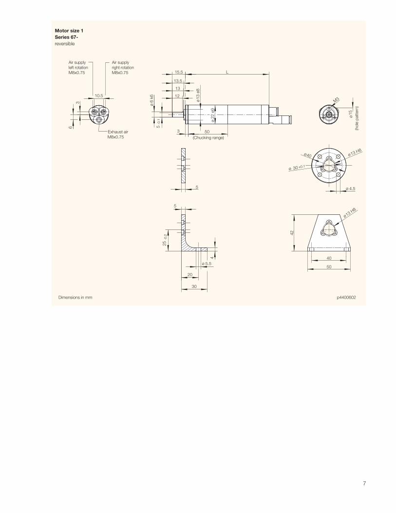
Length L mm / in. 96.5 / 3.76 96.5 / 3.76 105.5 / 4.1 105.5 / 4.1 113.5 / 4.4
Weight kg / lbs 0.2 / 0.4 0.2 / 0.4 0.22 / 0.5 0.22 / 0.5 0.29 / 0.6
Hose I.D. mm / in. 4 / 5/32 4 / 5/32 4 / 5/32 4 / 5/32 4 / 5/32
for Motor size 1
Flange Part no. 445181
necessary 3 cylinder-screws Part no. 831728
Bracket Part no. 445180
necessary 3 cylinder-screws Part no. 831728
3 Slide connectors (M8 x 0.75) Part no. included in delivery
2 Silencer Part no. 823236
necessary 2 Slide connectors Part no. 824838
1 Hose 0.2 m Part no. 822283
Maintenance unit with lubricator* Part no. 820454 A
Connection thread G 1/4
Maintenance unit without lubricator* Part no. 822408 A
Connection thread G 1/4
Replacement part set consisting of:
vanes, sealant rings, o-rings and silencers Part no. 446084 B
Optional Equipment
Of course you can also purchase individual
replacement parts from us.Allowable shaft loading see page 24.
Further notes for soundproofing
see page 25.
7
ø13 H8ø40
ø 30 ±0.1
ø13 H8
p4400602Dimensions in mm
Air supply
left rotation
M8x0.75
Air supply
right rotation
M8x0.75
Exhaust air
M8x0.75
42
40
50
4
ø 5.5
20
30
25
-0.2
5
5 ø 4.5
50
L
ø2
2 e
9
ø1
3 e
8
3
12
13
13.5
15.5
ø6
k6
5 -0
.1
M3
ø
(ho
le p
att
ern
)
15
10.5
3
6
(Chucking range)
Motor size 1
Series 67-
reversible

8
120 W ADVANCED LINE AIR MOTOR
Motor size 2 reversible
Series 67- Type 67-002 67-012 67-022 67-032 67-042 67-052 67-2521
Part no. 444550 A 444550 H 444550 B 444550 C 444550 D 444550 E 444550 F
Nominal-Power W / HP 120 / 0.16 120 / 0.16 120 / 0.16 120 / 0.16 120 / 0.16 120 / 0.16 90 / 0.12 1)
Nominal-Speed rpm 11000 2750 1800 700 450 300 501)
Speed (idling) rpm 22000 5500 3600 1400 900 600 100
Nominal-Torque Nm / in.lbs 0.10 / 0.9 0.4 / 3.5 0.6 / 5.3 1.6 / 14 2.5 / 22 3.8 / 34 5 / 44*)
Start torque min. Nm / in.lbs 0.15 / 1.3 0.6 / 5.3 0.9 / 8 2.4 / 21 3.8 / 34 5 / 44*) 5 / 44*)
Air consumption m3/min / cfm 0.3 / 11 0.3 / 11 0.3 / 11 0.3 / 11 0.3 / 11 0.3 / 11 0.3 / 11
Weight kg / lbs 0.35 / 0.8 0.35 / 0.8 0.35 / 0.8 0.4 / 0.9 0.4 / 0.9 0.4 / 0.9 0.45 / 1
Hose I.D. mm / in. 6 / ¼ 6 / ¼ 6 / ¼ 6 / ¼ 6 / ¼ 6 / ¼ 6 / ¼
*) max. admissible torque
1) theoretical values for issuing the power diagram
II 2 GD c IIC
T6 (80°C)
Of course you can also purchase individual
replacement parts from us.
Our standard maintenance units are ATEX
conform. Please contact us if this is a requirement.
Allowable shaft loading see page 24.Further notes for soundproofing
see page 25.
Performance data relate to an air pressure of 6 bar (85 PSI) and lubricated air. With oil-free operation the output will be reduced by 10 - 20%.
*) Maintenance unit consists of pressure regulator valve, filter and optionally with or without lubricator
for Motor size 2
Flange Part no. 444569
necessary 4 cylinder-screws Part no. 823216
Bracket Part no. 444572
necessary 4 cylinder-screws Part no. 823216
Silencer: motor operates in one direction
(right or left rotation)
1 Hose nozzle Part no. 823237
2 Silencer Part no. 823236
Silencer: motor is reversible
(right and left rotation)
2 Hose nozzles Part no. 823237
1 Silencer Part no. 823236
Maintenance unit with lubricator* Part no. 820454 A
Connection thread G 1/4
Maintenance unit without lubricator* Part no. 822408 A
Connection thread G 1/4
Replacement part set consisting of:
vanes, sealant rings, o-rings and silencers Part no. 445580 A
Optional EquipmentOptional Equipment

9
Dimensions in mm p4402205
Flange
(Optional equipment)
Bracket
(Optional equipment)
Silencer
(Optional equipment)
Air connectionright rotation
G1/8
Air connectionleft rotationG1/8
A1
17
A2
A3 - Chucking Range
ø2
7 e
8
ø8
k6
ø1
3 e
8
8.8
ø2 h9
M4
25
-0.2
14Exh
aust
air
G1/8
4
8
5
ø1
3 H
8
ø2
93
M3x1
0
ø4.5
ø1
3 H
8
4.5
ø2
9
2.5
ø5.5
20
30
4.5
40
50
ø5
0
ø4
0ø
21
42
A2x2x14
Motor
size
Series 67-
Type
Dimensions of motor (mm)
A1 A2 A3
2
67-002 67-012 67-022 135 117 46.5
67-032 67-042 67-052 147.5 129.5 59
67-2521 160 142 71.5
Motor size 2
Series 67-
reversible

10
200 W / 300 W ADVANCED LINE DRUCKLUFTMOTOR
Motor size 2.5 reversible
Series 67- Type 67-0025 67-0125 67-0225 67-0725 67-0325 67-0425 67-04251 67-24251
Part no. 444500 B 444500 C 444500 D 444500 F 444500 E 444500 A 444500 G 444500 H
Nominal-Power W / HP 200 / 0.27 200 / 0.27 200 / 0.27 200 / 0.27 200 / 0.27 200 / 0.27 100 / 0.13 180 / 0.241)
Nominal-Speed rpm 7250 2300 1200 700 350 160 90 251)
Speed (idling) rpm 14500 4600 2400 1400 700 320 180 50
Nominal-Torque Nm / in.lbs 0.26 / 2.3 0.8 / 7.1 1.6 / 14 2.7 / 24 5.4 / 48 12 / 106 10.5 / 93 20 / 177*)
Start torque min. Nm / in.lbs 0.4 / 3.5 1.2 / 11 2.4 / 21 4.1 / 36 8.2 / 73 18 / 159 15 / 133 20 / 177*)
Air consumption m3/min / cfm 0.37 / 13 0.37 / 13 0.37 / 13 0.37 / 13 0.37 / 13 0.37 / 13 0.27 / 9 0.37 / 13
Weight kg / lbs 0.7 / 1.5 0.75 / 1.6 0.75 / 1.6 0.85 / 1.9 0.85 / 1.9 0.85 / 1.9 0.85 / 1.9 0.95 / 2.1
Hose I.D. mm /in. 10 / 3/8 10 / 3/8 10 / 3/8 10 / 3/8 10 / 3/8 10 / 3/8 10 / 3/8 10 / 3/8
Motor size 3 reversible
Series 67- Type 67-003 67-013 67-023 67-073 67-083 67-093 67-0931 67-1931 67-2931
Part no. 444560 A 444560 B 444560 C 444560 D 444560 E 444560 F 444560 G 444560 K 444560 H
Nominal-Power W / HP 300 / 0.4 300 / 0.4 300 / 0.4 300 / 0.4 300 / 0.4 300 / 0.4 130 / 0.17 280/0.371) 280/0.371)
Nominal-Speed rpm 7250 2300 1200 700 300 170 90 50 251)
Speed (idling) rpm 14500 4600 2400 1400 600 340 180 100 50
Nominal-Torque Nm / in.lbs 0.4 / 3.5 1.2 / 11 2.4 / 21 4.1 / 36 9.6 / 85 16.9 / 149 13.8 / 122 36 / 319*) 36 / 319*)
Start torque min. Nm / in.lbs 0.6 / 5.3 1.9 / 17 3.6 / 32 6.1 / 54 14.3 / 126 25.3 / 224 21 / 186 36 / 319*) 36 / 319*)
Air consumption m3/min / cfm 0.47 / 17 0.47 / 17 0.47 / 17 0.47 / 17 0.47 / 17 0.47 / 17 0.28 / 10 0.47 / 17 0.47 / 17
Weight kg / lbs 1.0 / 2.2 1.05 / 2.3 1.05 / 2.3 1.10 / 2.4 1.15 / 2.5 1.15 / 2.5 1.15 / 2.5 1.25 / 2.7 1.25 / 2.7
Hose I.D. mm / in. 10 / 3/8 10 / 3/8 10 / 3/8 10 / 3/8 10 / 3/8 10 / 3/8 10 / 3/8 10 / 3/8 10 / 3/8
II 2 GD c IIC
T6 (80°C)
II 2 GD c IIC
T6 (80°C)
*) max. admissible torque
1) theoretical values for issuing the power diagram
*) max. admissible torque
1) theoretical values for issuing the power diagram
*) Maintenance unit consists of pressure regulator valve, filter and optionally with or without lubricator
Performance data relate to an air pressure of 6 bar (85 PSI) and lubricated air. With oil-free operation the output will be reduced by 10 - 20%.
Performance data relate to an air pressure of 6 bar (85 PSI) and lubricated air. With oil-free operation the output will be reduced by 10 - 20%.
for Motor size 2.5 for Motor size 3
Flange Part no. 444530 444610
necessary 4 cylinder-screws Part no. 823216 823139
Bracket Part no. 444539 444611
necessary 4 cylinder-screws Part no. 823216 823139
Silencer: motor operates in one direction
(right or left rotation)
1 Hose nozzle Part no. 823238 (1/8”) 410541 (1/4”)
1 Silencer Part no. 802675 (1/8”) 802673 (1/4”)
1 Silencer Part no. 802673 (1/4”) 802673 (1/4”)
Silencer: motor is reversible
(right or left rotation)
2 Hose nozzles Part no. 823238 (1/8”) 410541 (1/4”)
1 Silencer Part no. 802673 (1/4”) 802673 (1/4”)
Maintenance unit with lubricator* Part no. 820454 A 820455 A
Connection thread G 1/4 G 1/2
Maintenance unit without lubricator* Part no. 822408 A 822409 A
Connection thread G 1/4 G 1/2
Replacement part set consisting of:
vanes, sealant rings, o-rings and silencers Part no. 444785 A 444786 A
Optional Equipment
Of course you can also purchase individual
replacement parts from us.
Our standard maintenance units are ATEX
conform. Please contact us if this is a requirement.
Allowable shaft loading see page 24.Further notes for soundproofing
see page 25.

11
Flange
(Optional Equipment)
Bracket
(Optional Equipment)
p4402777Dimensions in mm
Silencer
(Optional Equipment)
Air connection
right rotation
D1
A1
A2
A3
A4 - Chucking range
B2
k6
B3
e8
B1
e8
C2 h9
C4
C1
D37
D2
Exhaust
air
G1/4
B3
e8
E5
E1
E2
E3
E4
4.5
30
-0.2
30
ø6.6
20 4.5
F1
F2
C3
ø5
.5
C5
E5
F3
for motor size 2.5: A3x3x18for motor size 3:- types 67-003/-013/-023/-073: A4x4x20- types 67-083/-093/-0931/-1931/-2931: A5x5x20
Air connection
left rotation
D1
Motor
size
Series 67-
Type
Dimensions of flange (mm) Dimensions of bracket (mm)
B3 E1 E2 E3 E4 E5 F1 F2 F3
2.5
67-0025 67-0125 67-0225
20 5 5.8 60 50 17 45 55 4767-0725 67-0325 67-0425 67-04251
67-24251
3
67-003 67-013 67-023
24 6 6.8 65 55 21 50 60 4867-073
67-083 67-093 67-0931
67-1931 67-2931
Motor
size
Series 67-
Type
Dimensions of motor (mm)
A1 A2 A3 A4 B1 B2 B3 C1 C2 C3 C4 C5 D1 D2 D3
2.5
67-0025 67-0125 67-0225 151
23
127 64
38 10 20 11.2 3 30 M4 1.6 G1/8 8 1967-0725 67-0325 67-0425 67-04251 167 143 80
67-24251 183 159 96
3
67-003 67-013 67-023 17127
143 66
42
12
24
13.5 4
34 M5
M4x12
G1/4 11 2067-073 187
1598267-083 67-093 67-0931 191 30
14 16 5 M5x1267-1931 67-2931 196 31 164
Motor size 2.5 and Motor size 3
Series 67-
reversible

12
285 W ADVANCED LINE HIGH TORQUE MOTOR
*) Maintenance unit consists of pressure regulator valve, filter and optionally with or without lubricator
**) no. of cylinder screws required
for Motor size 3 for Motor size 3
Type 67-313 to 67-373 Type 67-413 to 67-423
Flange Part no. 413462 413463
necessary cylinder-screws Part no. 823148 (8 pieces)** 823545 (6 pieces)**
Bracket Part no. 4446172 4446173
necessary cylinder-screws Part no. 823148 (8 pieces)** 823545 (6 pieces)**
Silencer: motor operates in one direction
(right or left rotation)
1 Hose nozzle Part no. 410541 (1/4”) 410541 (1/4”)
2 Silencer Part no. 802673 (1/4”) 802673 (1/4”)
Silencer: motor is reversible
(right or left rotation)
2 Hose nozzles Part no. 410541 (1/4”) 410541 (1/4”)
1 Silencer Part no. 802673 (1/4”) 802673 (1/4”)
Maintenance unit with lubricator* Part no. 820455 A 820455 A
Connection thread G 1/2 G 1/2
Maintenance unit without lubricator* Part no. 822409 A 822409 A
Connection thread G 1/2 G 1/2
Replacement part set consisting of:
vanes, sealant rings, o-rings and silencers Part no. 444786 B 444786 C
Optional Equipment
Motor size 3 with high torque reversible
Series 67- Type 67-313 67-323 67-373 67-413 67-423
Part no. 444560 I 444560 L 444560 M 444560 N 444560 O
Nominal-Power W / HP 285 / 0.38 285 / 0.38 280 / 0.37 280 / 0.37 280 / 0.37
Nominal-Speed rpm 85 40 25 13 7
Speed (idling) rpm 170 80 50 26 14
Nominal-Torque Nm / in.lbs 32 / 283.2 62 / 548.7 110 / 973.5 210 / 1858.5 410 / 3628.5
Start torque min. Nm / in.lbs 47 / 416 92 / 814 162 / 1433.7 320 / 2832 615 / 5442.8
Air consumption m3/min / cfm 0.47 / 16.6 0.47 / 16.6 0.47 / 16.6 0.47 / 16.6 0.47 / 16.6
Weight kg / lbs 2.7 / 5.9 2.6 / 5.7 2.9 / 6.4 3.5 / 7.7 3.5 / 7.7
Hose I.D. mm / in. 10 / 3/8 10 / 3/8 10 / 3/8 10 / 3/8 10 / 3/8
II 2 GD c IIC
T6 (80°C)
Performance data relate to an air pressure of 6 bar (85 PSI) and lubricated air. With oil-free operation the output will be reduced by 10 - 20%.
Of course you can also purchase individual
replacement parts from us.
Our standard maintenance units are ATEX
conform. Please contact us if this is a requirement.
Allowable shaft loading see page 24.Further notes for soundproofing
see page 25.

13
ø4
2 d
9
92
C6
C3
D2 h9
32
50
0 -0.2
C1
9.5
C8
C5
C1
e8
10.5
SW
17
A1
A3
B2
k6
D1
B3
e8
B1
e8
11 6
.5
20
Exhaust air
G1/4
9.5
C7
110
B4
C4
C3
C2
C4
C2 C3
1.5
C1
A2
32
A4 - Chucking range
B6
ø11
90
C6
9.5
50
Dimensions in mm p444204
Flange
(Optional Equipment)
Bracket
(Optional Equipment)
Pitch:
type 67-313/-323/-373: 8 x 45°
type 67-413/-423: 6 x 60°
types 67-313/-323/-373: A6x6x32
types 67-413/-423: A8x7x32
Air connection
right rotation
G1/4
L R
B5
Silencer
(Optional Equipment)
Air connection
right rotation
G1/4
Pitch:
Motor
size
Series 67-
Type
Dimensions of motor (mm)
A1 A2 A3 A4 B1 B2 B3 B4 B5 B6 C1 C2 C3 C4 C5 C6 C7 C8 D1 D2
3
67-313 67-323 254.144 42
133.156 19 35 48 M6 M6x12 35 11 6.6 4 32 48 70 85 21.5 6
67-373 269.9 148.9
67-413 67-423 279.2 47 45 155.2 63 24 34 45 M8 M8x19 34 13 8.4 5 30 45 79 95 27 8
Motor size 3 High torque stainless steel motors
Series 67-
reversible

14
Motor size 2.5 with holding brake reversible
Series 67- Type 67-0025 B 67-0125 B 67-0225 B 67-0725 B 67-0325 B 67-0425 B
ATEX konform Part no. 4457602B 4457602C 4457602D 4457602F 4457602E 4457602A
Series 67- Type 67-0025 B 67-0125 B 67-0225 B 67-0725 B 67-0325 B 67-0425 BPart no. 445760 B 445760 C 445760 D 445760 F 445760 E 445760 A
Nominal-Power W / HP 200 / 0.27 200 / 0.27 200 / 0.27 200 / 0.27 200 / 0.27 200 / 0.27
Nominal-Speed rpm 7250 2300 1200 700 350 160
Speed (idling) rpm 14500 4600 2400 1400 700 320
Nominal-Torque Nm / in.lbs 0.26 / 2.3 0.8 / 7.1 1.6 / 14 2.7 / 24 5.4 / 48 12 / 106
Start torque min. Nm / in.lbs 0.4 / 3.5 1.2 / 11 2.4 / 21 4.1 / 36 8.2 / 73 18 / 159
Brake-Torque Nm / in.lbs 0.52 / 4.6 1.6 / 14.2 3.2 / 28 5.4 / 48 10.8 / 96 20 / 177*)
Brems-Drehmoment Nm / in.lbs 1 / 9 3.4 / 30 6.7 / 59 11.8 / 104 20 / 177*) 20 / 177*)
Air consumption m3/min / cfm 0.37 / 13 0.37 / 13 0.37 / 13 0.37 / 13 0.37 / 13 0.37 / 13
Weight kg / lbs 1 / 2.2 1.05 / 2.3 1.05 / 2.3 1.15 / 2.5 1.15 / 2.5 1.15 / 2.5
Hose I.D. mm / in. 10 / 3/8 10 / 3/8 10 / 3/8 10 / 3/8 10 / 3/8 10 / 3/8
Motor size 3 with holding brake reversible
Series 67- Type 67-003 B 67-013 B 67-023 B 67-073 B 67-083 B 67-093 B
ATEX konform Part no. 457622A 4457622B 4457622C 4457622D 4457622E 4457622F
Series 67- Type 67-003 B 67-013 B 67-023 B 67-073 B 67-083 B 67-093 BPart no. 445762 A 445762 B 445762 C 445762 D 445762 E 445762 F
Nominal-Power W / HP 300 / 0.4 300 / 0.4 300 / 0.4 300 / 0.4 300 / 0.4 300 / 0.4
Nominal-Speed rpm 7250 2300 1200 700 300 170
Speed (idling) rpm 14500 4600 2400 1400 600 340
Nominal-Torque Nm / in.lbs 0.4 / 3.5 1.2 / 11 2.4 / 21 4.1 / 36 9.6 / 85 16.9 / 149
Start torque min. Nm / in.lbs 0.6 / 5.3 1.9 / 17 3.6 / 32 6.1 / 54 14.3 / 126 25.3 / 224
Brake-Torque Nm / in.lbs 0.8 / 7 2.4 / 21 4.8 / 42 8.2 / 72 19.2 / 170 33.8 / 299
Brems-Drehmoment Nm / in.lbs 1 / 9 3.4 / 30 6.7 / 59 11.8 / 104 20.6 / 182 36 / 318.6*)
Air consumption m3/min / cfm 0.47 / 17 0.47 / 17 0.47 / 17 0.47 / 17 0.47 / 17 0.47 / 17
Weight kg / lbs 1.35 / 3 1.4 / 3.1 1.4 / 3.1 1.45 / 3.2 1.5 / 3.3 1.5 / 3.3
Hose I.D. mm / in. 10 / 3/8 10 / 3/8 10 / 3/8 10 / 3/8 10 / 3/8 10 / 3/8
200 W / 300 W ADVANCED LINE AIR MOTOR WITH INTEGRATED HOLDING BRAKE
*) max. admissible torque
*) Maintenance unit consists of pressure regulator valve, filter and optionally with or without lubricator
Performance data relate to an air pressure of 6 bar (85 PSI) and lubricated air. With oil-free operation the output will be reduced by 10 - 20%.
Optional Equipment: for Motor size 2.5 for Motor size 3
Flange Part no. 444530 444610
necessary 4 cylinder-screws Part no. 823216 823139
Bracket Part no. 444539 444611
necessary 4 cylinder-screws Part no. 823216 823139
Silencer: motor operates in one direction
(right or left rotation)
1 Hose nozzle Part no. 823238 (1/8”) 410541 (1/4”)
1 Silencer Part no. 802675 (1/8”) 802673 (1/4”)
1 Silencer Part no. 802673 (1/4”) 802673 (1/4”)
Silencer: Motor is reversible
(right or left rotation)
2 Hose nozzles Part no. 823238 (1/8”) 410541 (1/4”)
1 Silencer Part no. 802673 (1/4”) 802673 (1/4”)
Maintenance unit with lubricator* Part no. 820454 A 820455 A
Connection thread G 1/4 G 1/2
Maintenance unit without lubricator* Part no. 822408 A 822409 A
Connection thread G 1/4 G 1/2
Replacement part set consisting of:
vanes, sealant rings, o-rings and silencers Part no. 444785 A 444786 A
Replacement part set for brake consisting of:
discs, pressure spring and o-rings Part no. 446096 C 446096 C
Of course you can also purchase individual repla-
cement parts from us.
Our standard maintenance units are ATEX con-
form. Please contact us if this is a requirement.
Allowable
shaft loading
see page 24.
Further notes
for sound-
proofing see
page 25.
A pressure regulator valve is included within our ship-
ment of the ATEX conform brake motors. This safety
valve turns off the air supply in the brake leads
automatically when the pressure falls under 5 bar.
This prevents an irregular temperatur increase.
II 2 GD c IIC
T6 (80°C)
II 2 GD c IIC
T6 (80°C)

15
A1
A2
A3
A4-Chucking range
A5
B1
e8
B2
k6
B3
e8
C1
C2 h9
C4
C3
D3
7
D2
E3
ø5.
5
F2
F1
4.5
4.5
20
30 -0
.2E
5
B3
e8
E2
E1
E4
Exhaust air
G1/4
ø6.6
28
.9
ø4
30
F3
Flange
(Optional Equipment)
Bracket
(Optional Equipment)
p4134552Dimensions in mm
Silencer
(Optional Equipment)
Pilot air port for motor brake
required air pressure
> 5 bar (70.8 PSI)
C5
Air connection
left rotation
D1
Motor size 2.5: A3x3x18
Motor size 3:
types 67-003/-013/-023/-073 B: A4x4x20
types 67-083/-093 B: A5x5x20
Air connection
right rotation
D1
Motor
size
Series 67-
Type
Dimensions of flange (mm) Dimensions of bracket (mm)
B3 E1 E2 E3 E4 E5 F1 F2 F3
2.567-0025 B 67-0125 B 67-0225 B
20 5 5.8 60 50 17 55 45 4767-0725 B 67-0325 B 67-0425 B
3
67-003 B 67-013 B 67-023 B
24 6 6.8 65 55 21 60 50 4867-073 B
67-083 B 67-093 B
Motor
size
Series 67-
Type
Dimensions of motor (mm)
A1 A2 A3 A4 A5 B1 B2 B3 C1 C2 C3 C4 C5 D1 D2 D3
2.567-0025 B 67-0125 B 67-0225 B 194
23170 64
98 38 10 20 11.2 3 30 M4 1.6 G1/8 8 1967-0725 B 67-0325 B 67-0425 B 210 186 80
3
67-003 B 67-013 B 67-023 B 21527
187 66
110 4212
2413.5 4
34 M5M4x12
G1/4 11 2067-073 B 231203 82
67-083 B 67-093 B 235 30 14 16 5 M5x12
Motor size 2.5 and Motor size 3 with holding break
Series 67-
reversible

16
600 W / 900 W ADVANCED LINE AIR MOTOR
Motor size 6 reversible
Series 67- Type 67-006 67-016 67-026 67-036 67-046 67-056 67-066 67-0661
Part no. 444570 A 444570 H 444570 B 444570 C 444570 D 444570 E 444570 F 444570 G
Series 67- Type – 67-016B16 67-026B16 67-036B16 67-046B16 67-056B16 67-066B16 67-0661B16for Drill-Chuck Part no. – 445353 H 445353 B 445353 C 445353 D 445353 E 445353 F 445353 G
Nominal-Power W / HP 600 / 0.8 600 / 0.8 600 / 0.8 600 / 0.8 600 / 0.8 600 / 0.8 600 / 0.8 300 / 0.4
Nominal-Speed rpm 7000 1750 1350 850 315 240 150 75
Speed (idling) rpm 14000 3500 2700 1700 630 480 300 150
Nominal-Torque Nm / in.lbs 0.82 / 7 3.2 / 28 4.2 / 37 6.7 / 59 18 / 159 24 / 212 38 / 336 38 / 336
Start torque min. Nm / in.lbs 1.23 / 11 4.8 / 42 6.4 / 57 10.1 / 89 27 / 239 36 / 319 57 / 504 57 / 504
Air consumption m3/min / cfm 0.85 / 30 0.85 / 30 0.85 / 30 0.85 / 30 0.85 / 30 0.85 / 30 0.85 / 30 0.55 / 19
Weight kg / lbs 2.2 / 4.8 2.3 / 5 2.3 / 5 2.3 / 5 2.6 / 5.7 2.7 / 5.9 2.7 / 5.9 2.7 / 5.9
Hose I.D. mm / in. 12 / 1/2 12 / 1/2 12 / 1/2 12 / 1/2 12 / 1/2 12 / 1/2 12 / 1/2 12 / 1/2
Motor size 7 reversible
Series 67- Type 67-007 67-017 67-027 67-037 67-047 67-057 67-067
Part no. 440066 A 440066 H 440066 B 440066 C 440066 D 440066 E 440066 F
Nominal-Power W / HP 900 / 1.2 900 / 1.2 900 / 1.2 900 / 1.2 900 / 1.2 900 / 1.2 900 / 1.2
Nominal-Speed rpm 6000 1750 1350 850 315 240 150
Speed (idling) rpm 12000 3500 2700 1700 630 480 300
Nominal-Torque Nm / in.lbs 1.4 / 12.4 4.9 / 43.4 6.3 / 55.7 10.1 / 89.4 27 / 238.9 35 / 309.7 57 / 504.5
Start torque min. Nm / in.lbs 2.1 / 18.6 7.3 / 64.6 9.5 / 84.1 15.2 / 134.5 40 / 354 53 / 469 85 / 752
Air consumption m3/min / cfm 1.4 / 49.4 1.4 / 49.4 1.4 / 49.4 1.4 / 49.4 1.4 / 49.4 1.4 / 49.4 1.4 / 49.4
Weight kg / lbs 2.5 / 5.5 2.6 / 5.7 2.6 / 5.7 2.6 / 5.7 2.9 / 6.4 3 / 6.6 3 / 6.6
Hose I.D. mm / in. 12 / 1/2 12 / 1/2 12 / 1/2 12 / 1/2 12 / 1/2 12 / 1/2 12 / 1/2
Performance data relate to an air pressure of 6 bar (85 PSI) and lubricated air. With oil-free operation the output will be reduced by 10 - 20%.
II 2 GD c IIC
T6 (80°C)
II 2 GD c IIC
T6 (80°C)
Optional Equipment: for Motor size 6 for Motor size 7
Flange Part no. 444616 444616
necessary 4 cylinder-screws Part no. 823148 823148
Bracket Part no. 444617 444617
necessary 4 cylinder-screws Part no. 823148 823148
Silencer: motor operates in one direction
(right or left rotation)
1 Hose nozzle Part no. 410540 (3/8”) 410540 (3/8”)
1 Silencer Part no. 802671 (3/8”) 802671 (3/8”)
1 Silencer Part no. 802666 (1/2”) 802666 (1/2”)
Silencer: Motor is reversible
(right or left rotation)
2 Hose nozzles Part no. 410540 (3/8”) 410540 (3/8”)
1 Silencer Part no. 802666 (1/2”) 802666 (1/2”)
Drill-Chuck
Range 1 - 13 mm / B 16 Part no. 804652 –
Quick change chuck
Range 1 - 13 mm / B 16 Part no. 804663 –
Maintenance unit with lubricator* Part no. 820455 A 821608 A
Connection thread G 1/2 G 3/4
Maintenance unit without lubricator* Part no. 822409 A 826982 A
Connection thread G 1/2 G 3/4
Replacement part set consisting of: Part no. 444787 A / for Part no. 444570 A-D, H 444919 A / for Part no. 440066 A-D, H
vanes, sealant rings, o-rings and silencers for Part no. 445353 B-D, H 444919 B / for Part no. 440066 E-F
Part no. 444787 B / for Part no. 444570 E-G
for Part no. 445353 E-G
*) Maintenance unit consists of pressure regulator valve, filter and optionally with or without lubricator
**) no. of cylinder screws required
Of course you can also purchase individual
replacement parts from us.
Our standard maintenance units are ATEX
conform. Please contact us if this is a requirement.
Allowable shaft loading see page 24.Further notes for soundproofing
see page 25.

17
p4402988Dimensions in mm
Flange
(Optional Equipment)
Bracket
(Optional Equipment)
67-016 B16
to
67-0661 B16
Silencer
(Optional Equipment)
Drill chuck cone
B16 DIN 238
Air connection
right rotation
G3/8
Air connection
left rotation
G3/8
A1
A2 A3
A4 - Chucking range
ø5
6 e
8
B1
k6
ø3
5 e
8
C3
M6
C1
C2 h9
48
Exhaust air
G1/2
14
11
.5
24
ø3
5 e
8
7.5
8.5
ø85
ø70
ø6.6
ø3
24
0 -0
.2
25
50
ø6.6
85
70
5.5
5.5
ø3
5 e
8
A2 A3
A1
69
.5
Motor size 6:
types 67-006/-016/-026/-036/-046: A5x5x20
types 67-056/-066/-0661: A6x6x22
Motor size 7:
types 67-007/-017/-027/-037/-047: A5x5x20
types 67-057/-067: A6x6x22
Motor
size
Series 67-
Type
Dimensions of motor (mm)
A1 A2 A3 A4 B1 C1 C2 C3
6
67-006 67-016 67-026 67-036 19730.5
166 6614 16 5 M5x12
67-046 215 184 84
67-056 67-066 67-0661 217 36 180 80.5 19 21.5 6 M6x12
67-016B16 67-026B16 67-036B16 20437.5
166 66
– – – –67-046B16 222 184 84
67-056B16 67-066B16 67-0661B16 219 38 180 80.5
7
67-007 67-017 67-027 67-037 21730.5
185.5 6714 16 5 M5x12
67-047 235 203.5 85
67-057 67-067 237 36 200 81 19 21.5 6 M6x12
Motor size 6 and Motor size 7
Series 67-
reversible

18
570 W / 860 W ADVANCED LINE HIGH TORQUE AIR MOTOR
*) Maintenance unit consists of pressure regulator valve, filter and optionally with or without lubricator
**) no. of cylinder screws required
for Motor size 6 / 7
Type 67-146 to 67-166 Type 67-516
Type 67-147 to 67-167 Type 67-517
Flange Part no. 413462 413463
necessary 4 cylinder-screws Part no. 823148 (8 pieces)** 823545 (6 pieces)**
Bracket Part no. 4446172 4446173
necessary 4 cylinder-screws Part no. 823148 (8 pieces)** 823545 (6 pieces)**
Silencer: motor operates in one direction
(right or left rotation)
1 Hose nozzle Part no. 410540 (3/8”)
1 Silencer Part no. 802671 (3/8”)
1 Silencer Part no. 802666 (1/2”)
Silencer: Motor is reversible
(right or left rotation)
2 Hose nozzles Part no. 410540 (3/8”)
1 Silencer Part no. 802666 (1/2”)
for Motor size 6 for Motor size 7
Maintenance unit with lubricator* Part no. 820455 A 821608 A
Connection thread G 1/2 G 3/4
Maintenance unit without lubricator* Part no. 822409 A 826982 A
Connection thread G 1/2 G 3/4
Replacement part set consisting of: 444787 D / for Type 67-146 to 67-166 444919 C / for Type 67-147 to 67-167
vanes, sealant rings, o-rings and silencers Part no. 444787 E / for Type 67-516 444919 D / for Type 67-517
Optional Equipment
Motor size 6 reversible
Series 67- Type 67-146 67-156 67-166 67-516
Part no. 444570 I 444570 K 444570 L 444570 M
Nominal-Power W / HP 570 / 0.76 570 / 0.76 570 / 0.76 565 / 0.757
Nominal-Speed rpm 75 55 37 20
Speed (idling) rpm 150 110 74 40
Nominal-Torque Nm / in.lbs 72 / 637.2 98 / 867.3 150 / 1327.5 265 / 2345.3
Start torque min. Nm / in.lbs 108 / 955.8 147 / 1301 225 / 1991.3 400 / 3540
Air consumption m3/min / cfm 0.85 / 30 0.85 / 30 0.85 / 30 0.85 / 30
Weight kg / lbs 3.6 / 7.9 3.6 / 7.9 3.6 / 7.9 4.4 / 9.7
Hose I.D. mm / in. 12 / 1/2 12 / 1/2 12 / 1/2 12 / 1/2
Motor size 7 reversible
Series 67- Type 67-147 67-157 67-167 67-517
Part no. 440066 I 440066 K 440066 L 440066 M
Nominal-Power W / HP 860 / 1.15 860 / 1.15 860 / 1.15 850 / 1.14
Nominal-Speed rpm 75 55 35 20
Speed (idling) rpm 150 110 70 40
Nominal-Torque Nm / in.lbs 110 / 973.5 150 / 1327.5 225 / 1991.3 400 / 3540
Start torque min. Nm / in.lbs 160 / 1416 220 / 1947 335 / 2964.8 600 / 5310
Air consumption m3/min / cfm 1.4 / 49.4 1.4 / 49.4 1.4 / 49.4 1.4 / 49.4
Weight kg / lbs 3.8 / 8.4 3.9 / 8.6 3.9 / 8.6 4.7 / 10.3
Hose I.D. mm / in. 12 / 1/2 12 / 1/2 12 / 1/2 12 / 1/2
II 2 GD c IIC
T6 (80°C)
II 2 GD c IIC
T6 (80°C)
Performance data relate to an air pressure of 6 bar (85 PSI) and lubricated air. With oil-free operation the output will be reduced by 10 - 20%.
Performance data relate to an air pressure of 6 bar (85 PSI) and lubricated air. With oil-free operation the output will be reduced by 10 - 20%.
Of course you can also purchase individual
replacement parts from us.
Our standard maintenance units are ATEX
conform. Please contact us if this is a requirement.
Allowable shaft loading see page 24.Further notes for soundproofing
see page 25.

19
p444338Dimensions in mm
Flange
(Optional Equipment)
Bracket
(Optional Equipment)
Silencer
(Optional Equipment)
Exhaust air
G1/2
92
C7
B5
D2 h9
SW
17
C6
32
9.5
C5
9.5
10.5
C5
C1
e8
C8
A1
B1
e8
B3
e8
B2
k6
D1
A324
11
.5
14
B4
C1
e8
C2
C3
1.5
C4
1.5
C3
C2
C1
C4
32
A2
110
A4A5-Chucking range
C3
ø11
B6
9.5
90
C6
50
types 67-516/-517: A8x7x32
all other types: A6x6x32
Pitch
8x45° - 67-146/156/166
8x45° - 67-147/157/167
6x60° - 67-516/517
Air connection
left rotation
G3/8Air connection
right rotation
G3/8
Motor
size
Series 67-
Type
Dimensions of motor (mm)
A1 A2 A3 A4 A5 B1 B2 B3 B4 B5 B6 C1 C2 C3 C4 C5 C6 C7 C8 D1 D2
667-146 67-156 67-166 283.4 44 42 98.5 61 56 e8 19 35 48 M6 M6x12 35 11 6.6 4.4 32 48 70 85 21.5 6
67-516 347 47 45 98.5 84.2 63 h8 24 34 45 M8 M8x19 34 13.1 8.4 5.4 30 45 79 95 27 8
Motor
size
Series 67-
Type
Dimensions of motor (mm)
A1 A2 A3 A4 A5 B1 B2 B3 B4 B5 B6 C1 C2 C3 C4 C5 C6 C7 C8 D1 D2
767-147 67-157 67-167 303.4 44 42 118.5 61 56 e8 19 35 48 M6 M6x12 35 11 6.6 4.4 32 48 70 85 21.5 6
67-517 320.1 47 45 118.5 84.2 63 h8 24 34 45 M8 M8x19 34 13.1 8.4 5.4 30 45 79 95 27 8
Motor size 6 and Motor size 7 High torque stainless steel motors
Series 67-
reversible
20
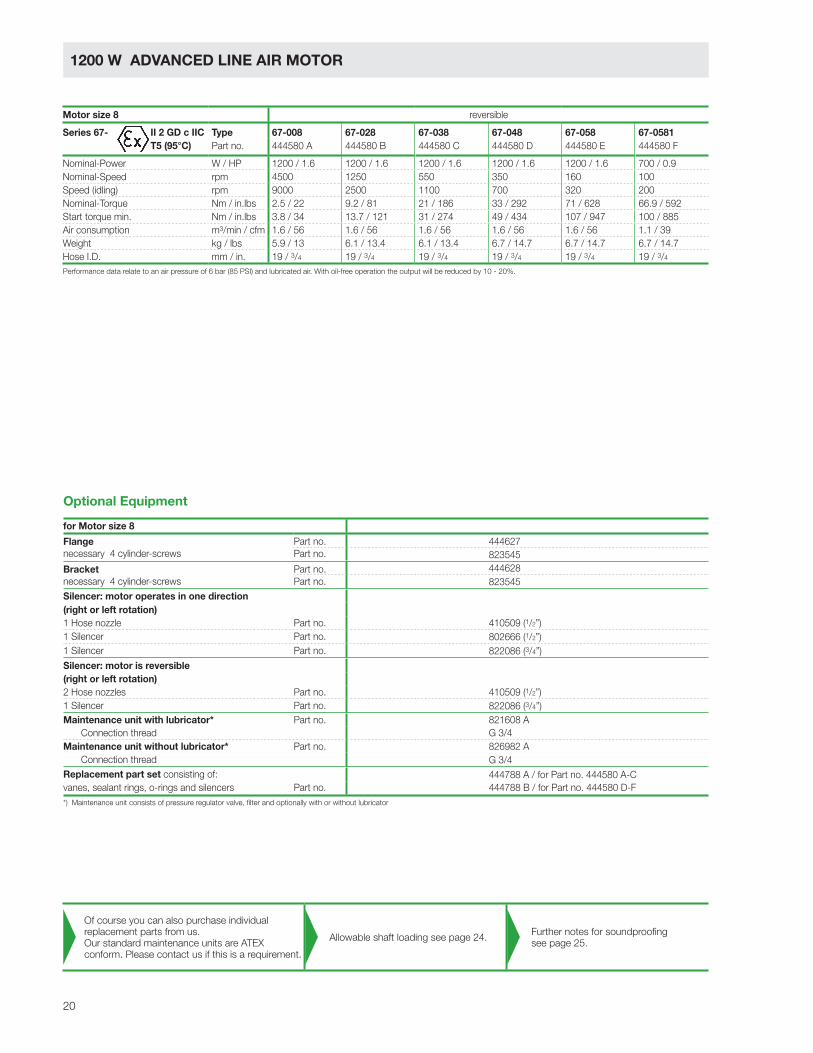
1200 W ADVANCED LINE AIR MOTOR
Motor size 8 reversible
Series 67- Type 67-008 67-028 67-038 67-048 67-058 67-0581
Part no. 444580 A 444580 B 444580 C 444580 D 444580 E 444580 F
Nominal-Power W / HP 1200 / 1.6 1200 / 1.6 1200 / 1.6 1200 / 1.6 1200 / 1.6 700 / 0.9
Nominal-Speed rpm 4500 1250 550 350 160 100
Speed (idling) rpm 9000 2500 1100 700 320 200
Nominal-Torque Nm / in.lbs 2.5 / 22 9.2 / 81 21 / 186 33 / 292 71 / 628 66.9 / 592
Start torque min. Nm / in.lbs 3.8 / 34 13.7 / 121 31 / 274 49 / 434 107 / 947 100 / 885
Air consumption m3/min / cfm 1.6 / 56 1.6 / 56 1.6 / 56 1.6 / 56 1.6 / 56 1.1 / 39
Weight kg / lbs 5.9 / 13 6.1 / 13.4 6.1 / 13.4 6.7 / 14.7 6.7 / 14.7 6.7 / 14.7
Hose I.D. mm / in. 19 / 3/4 19 / 3/4 19 / 3/4 19 / 3/4 19 / 3/4 19 / 3/4
II 2 GD c IIC
T5 (95°C)
*) Maintenance unit consists of pressure regulator valve, filter and optionally with or without lubricator
Performance data relate to an air pressure of 6 bar (85 PSI) and lubricated air. With oil-free operation the output will be reduced by 10 - 20%.
for Motor size 8
Flange Part no. 444627
necessary 4 cylinder-screws Part no. 823545
Bracket Part no. 444628
necessary 4 cylinder-screws Part no. 823545
Silencer: motor operates in one direction
(right or left rotation)
1 Hose nozzle Part no. 410509 (1/2”)
1 Silencer Part no. 802666 (1/2”)
1 Silencer Part no. 822086 (3/4”)
Silencer: motor is reversible
(right or left rotation)
2 Hose nozzles Part no. 410509 (1/2”)
1 Silencer Part no. 822086 (3/4”)
Maintenance unit with lubricator* Part no. 821608 A
Connection thread G 3/4
Maintenance unit without lubricator* Part no. 826982 A
Connection thread G 3/4
Replacement part set consisting of: 444788 A / for Part no. 444580 A-C
vanes, sealant rings, o-rings and silencers Part no. 444788 B / for Part no. 444580 D-F
Optional Equipment
Of course you can also purchase individual
replacement parts from us.
Our standard maintenance units are ATEX
conform. Please contact us if this is a requirement.
Allowable shaft loading see page 24.Further notes for soundproofing
see page 25.

21
Bracket
(Optional Equipment)
Flange
(Optional Equipment)
Silencer
(Optional Equipment)
Air connection
right rotationG1/2
Air connection
left rotationG1/2
A1
A2 A3
A4 - Chucking range
ø8
2 e
8
ø5
0 e
8
B1
k6
M8Exhaust air
G3/4
12
.5
22
ø9
ø1
00
ø6
8
11.5
C2
C1
10
ø4
6
ø5
0 e
8
60
0 -0.2
9.5
ø11
35
50
9.5
92
110
99
.5
ø1
15
39
C3
Dimensions in mm p440236
types 67-008/-028/-038: A6x6x32
types 67-048/-058/-0581: A8x7x50
Motor
size
Series 67-
Type
Dimensions of motor (mm)
A1 A2 A3 A4 B1 C1 C2 C3
867-008 67-028 67-038 235 35 197 65 19 21.5 6 M6x15
67-048 67-058 67-0581 268 60 205 73 28 31 8 M10x20
Motor size 8
Series 67-
reversible
22
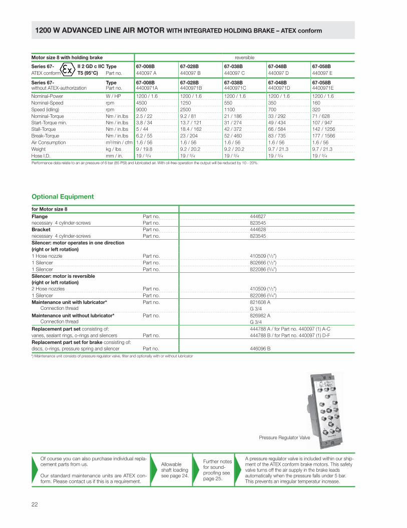
1200 W ADVANCED LINE AIR MOTOR WITH INTEGRATED HOLDING BRAKE – ATEX conform
Pressure Regulator Valve
Motor size 8 with holding brake reversible
Series 67- Type 67-008B 67-028B 67-038B 67-048B 67-058B
ATEX conform Part no. 440097 A 440097 B 440097 C 440097 D 440097 E
Series 67- Type 67-008B 67-028B 67-038B 67-048B 67-058Bwithout ATEX-authorization Part no. 4400971A 4400971B 4400971C 4400971D 4400971E
Nominal-Power W / HP 1200 / 1.6 1200 / 1.6 1200 / 1.6 1200 / 1.6 1200 / 1.6
Nominal-Speed rpm 4500 1250 550 350 160
Speed (idling) rpm 9000 2500 1100 700 320
Nominal-Torque Nm / in.lbs 2.5 / 22 9.2 / 81 21 / 186 33 / 292 71 / 628
Start-Torque min. Nm / in.lbs 3.8 / 34 13.7 / 121 31 / 274 49 / 434 107 / 947
Stall-Torque Nm / in.lbs 5 / 44 18.4 / 162 42 / 372 66 / 584 142 / 1256
Break-Torque Nm / in.lbs 6.2 / 55 23 / 204 52 / 460 83 / 735 177 / 1566
Air Consumption m3/min / cfm 1.6 / 56 1.6 / 56 1.6 / 56 1.6 / 56 1.6 / 56
Weight kg / lbs 9 / 19.8 9.2 / 20.2 9.2 / 20.2 9.7 / 21.3 9.7 / 21.3
Hose I.D. mm / in. 19 / 3/4 19 / 3/4 19 / 3/4 19 / 3/4 19 / 3/4
Performance data relate to an air pressure of 6 bar (85 PSI) and lubricated air. With oil-free operation the output will be reduced by 10 - 20%.
II 2 GD c IIC
T5 (95°C)
*) Maintenance unit consists of pressure regulator valve, filter and optionally with or without lubricator
for Motor size 8
Flange Part no. 444627
necessary 4 cylinder-screws Part no. 823545
Bracket Part no. 444628
necessary 4 cylinder-screws Part no. 823545
Silencer: motor operates in one direction
(right or left rotation)
1 Hose nozzle Part no. 410509 (1/2”)
1 Silencer Part no. 802666 (1/2”)
1 Silencer Part no. 822086 (3/4”)
Silencer: motor is reversible
(right or left rotation)
2 Hose nozzles Part no. 410509 (1/2”)
1 Silencer Part no. 822086 (3/4”)
Maintenance unit with lubricator* Part no. 821608 A
Connection thread G 3/4
Maintenance unit without lubricator* Part no. 826982 A
Connection thread G 3/4
Replacement part set consisting of: 444788 A / for Part no. 440097 (1) A-C
vanes, sealant rings, o-rings and silencers Part no. 444788 B / for Part no. 440097 (1) D-F
Replacement part set for brake consisting of:
discs, o-rings, pressure spring and silencer Part no. 446096 B
Optional Equipment
Of course you can also purchase individual repla-
cement parts from us.
Our standard maintenance units are ATEX con-
form. Please contact us if this is a requirement.
Allowable
shaft loading
see page 24.
Further notes
for sound-
proofing see
page 25.
A pressure regulator valve is included within our ship-
ment of the ATEX conform brake motors. This safety
valve turns off the air supply in the brake leads
automatically when the pressure falls under 5 bar.
This prevents an irregular temperatur increase.

23
p4401026Dimensions in mm
Flange
(Optional Equipment)
Bracket
(Optional Equipment)
Silencer
(Optional Equipment)
Air connection
right rotation
G1/2
Air connection
left rotation
G1/2
A1
A2
227
A3-Chucking range
130.5
159
180
ø8
2 e
8
B1
k6
ø5
0 e
8
C1
C2 h9
ø6
8
C3
M8Exhaust air
G3/4
22
12
.5
39
55
.5
92
110
60
-0.2
9.5
9.5
ø11
50
35
ø1
15
ø1
00
ø5
0 e
8
ø4
6
10
11.5
ø9
99
.5
types 67-008/-028/-038 B: A6x6x32
types 67-048/-058 B: A8x7x50
Pilot air port for motor brakerequired air pressure > 5 bar(70.8 PSI)
Motorsize
Series 67-with holding brake
Type
Dimensions of motor (mm)
A1 A2 A3 B1 C1 C2 C3
867-008 B 67-028 B 67-038 B 330 35 65 19 21.5 6 M6x15
67-048 B 67-058 B 363 60 73 28 31 8 M10x20
Motor size 8 with holding break
Series 67-
reversible

24
TECHNICAL DATA
Motors with threaded spindle
Motor size Part no. Fax
[N]
Frad
[N]
a
[mm]
MG 2 444950 A-H 380 110 0
MG 2.5 445910 A-L 570 450 0
MG 3 445682 A-D 570 860 0
MG 3 445682 E-H 790 820 0
Motors with drill chuck
Motor size Part no. Fax
[N]
Frad
[N]
a
[mm]
MG 6 445353 B-D, H 1100 150 80
MG 6 445353 E-G 1100 265 80
Allowable force for 10 million spindle rotations with 90 %
survival probability of bearing.
Allowable force for 10 million spindle rotations with 90 %
survival probability of bearing.
Motors with flattened shaft
Motor size Part no. Fax
[N]
Frad
[N]
a
[mm]
MG 0 445115 B,C,D,E 140 180 6
MG 0 445462 E 140 180 6
MG 1 445127 A-D 200 220 7
Motors with parallel key shaft
Motor size Part no. Part no.
with holding brake
Fax
[N]
Frad
[N]
a
[mm]
MG 2 444550 A-H 380 160 9
MG 2.5 444500 A-H 445760 A-F 570 720 12
MG 2.5 445184 A, B 1100 1200 22
MG 3 444560 A-D 445762 A-D 570 1130 14
MG 3 444560 E-H, K 445762 E, F 790 1070 15
MG 3 444560 I, L, M 1500 3500 21
MG 3 444560 N, O 1500 3500 20
MG 6 444570 A-D, H 1110 1300 15
MG 6 444570 E-G 1130 2090 18
MG 6 444570 I, K, L 1500 3500 21
MG 6 444570 M 1500 3500 22.5
MG 7 440066 A-D, H 1110 1300 15
MG 7 440066 E-F 1130 2090 18
MG 7 440066 I, K, L 1500 3500 21
MG 7 440066 M 1500 3500 22.5
MG 8 444580 A-C 440097 A-C, 4400971A-C 2330 2260 18
MG 8 444580 D-F 440097 D-E, 4400971D-E 2330 2700 30
Maximum allowable shaft load of the drive shaft
Allowable force for 10 million spindle rotations with 90 %
survival probability of bearing.
Allowable force for 10 million spindle rotations with 90 %
survival probability of bearing.
Fax
Frad
a
flattened shaftMotor size 0 and 1

25
TECHNICAL DATA
Noise level for motors of the series 67 -
without or with silencer (see optional equipment))
for Motor sizeNoise level dB (A)
without silencer
Noise level dB (A)
mit silencer
Part no.
silencer
0 98 85 811355
1 95 85 823236
2 99 92 823236
2.5 100 82 802675 / 802673
3 103 91 802673
6 104 94 802671 / 802666
7 106 88 802671 / 802666
8 108 95 802666 / 822086
Optional Silencer sets for further reduction of the noise level
Noise level of the motors
Silencer sets for motors of the build series 67 -
Attachment for only one rotation direction (clockwise or anticlockwise rotation)
for Motor size Part no. Hose length
mm
Noise level
dB (A)
1 446354 B 500 71
2 440015 B 500 70
2.5 440016 B 500 71
3 440018 B 500 70
6 440019 B 500 76
7 440019 B 500 79
8 440020 B 500 87
Silencer sets for motors of the build series 67 -
Attachment adjustable (clockwise and anticlockwise rotation)
for Motor size Part no. Hose length
mm
Noise level
dB (A)
1 446354 A 500 71
2 440015 A 500 70
2.5 440016 A 500 71
3 440018 A 500 70
6 440019 A 500 76
7 440019 A 500 79
8 440020 A 500 87
Motor
Motor
Silencer
Silencer
Use in potentially explosive environments The correspondingly marked motors are suitable for use in potentially
explosive environments.
1) Speed therefore for triplet of duro-plates, hard-paper and hard tissues, however instead of the HSS-drills we recommend quickly steel-drills equipped with hard-metal K 102) for thermos-plates, we recommend double the values
Cutting 35 m/min 28 m/min 25 m/min 14 m/min 11 m/min 7 m/min 22 m/min 12 m/min 50 m/min 90 m/min 165 m/min 210 m/ minSpeed (115 ft./min) (90 ft./min) (80 ft./min) (45 ft./min) (35 ft./min) (23 ft./min) (70 ft./min) (40 ft./min) (165 ft./min) (300 ft./min) (540 ft./min) (690 ft./min)
Carbon steel Alloy steel Stainless Cast-Iron Copper Lightweight-Metal Magnesium-Drill up to above steel up to above Bronze common Alloy2)dia. 500 500 - 700 700 700 - 900 900 - 1100 180 180 Brass alloy hardmm/in. N/mm2 N/mm2 N/mm2 N/mm2 N/mm2 N/mm2 N/mm2 mild brass1)
(30 (30 - 45 (45 (45 - 55 (55 - 70 (10 (10long tons/ long tons/ long tons/ long tons/ long tons/ long tons/ long tons/sq. in.) sq. in.) sq. in.) sq. in.) sq. in.) sq. in.) sq. in.)
1/0.04 11000 8800 7800 4400 3400 2200 7000 3800 16000 28000 52000 660002/5/64 5500 4400 3900 2200 1700 1100 3500 1900 8000 14000 26000 330003/1/8 3700 3000 2600 1500 1100 730 2300 1300 5300 9000 17300 220004/5/32 2800 2200 2000 1100 850 550 1700 950 4000 7000 13000 165005/13/64 2200 1800 1600 880 680 440 1400 760 3200 5600 10400 132006/15/64 1900 1500 1300 735 570 365 1200 630 2700 4800 8700 110007/ 9/32 1600 1300 1100 630 485 315 1000 540 2300 4000 7400 94008/5/16 1400 1100 975 550 425 275 875 475 2000 3500 6500 83009/23/64 1200 975 865 490 380 245 780 420 1800 3100 5800 740010/25/64 1100 880 780 440 340 220 700 380 1600 2800 5200 6600
Speed standard values (rpm) for HSS spiral-drills

26
The layout of your air motor:
Torque (M) %Power (P) %Air consumption (Q) %
Stall
Starting
Nominaltorque
Nom
inal
spee
d
Spe
edid
ling
Speed (n) %
Nominalpower
200
180
160
140
120
100
80
60
40
20
10 20 30 40 50 60 70 80 90 100
P
M
Q
100
90
80
70
60
50
40
30
20
10
torque
torque
P = Power Output in kW
M = Nominal-Torque in Nm
n = Nominal-Speed in rpm
M x n
9550P =
= optimal working range of the air motor
The optimal working range of an air motor is close to the nominal speed. If you need
lower speeds than are mentioned in the catalogue you can reduce the speed by throttling
the exhaust air with only a slight loss of power. By throttling the supply air or decreasing
the operating pressure the speed, torque and power are reduced.
All performance data of the DEPRAG air motors is based on operating pressure of 6 bar
and the opening cross-section mentioned in the motor data. If your application condi-
tions are different from this then you will find a comprehensive guide to the layout of our
motors in brochure D 6000 E.
Calculating the motor power

27
Do you need support in selecting the right drive system?
Tell us your operational conditions and our application consultants will be happy to help:
Application:
In what kind of environment
will the motor be installed?
ATEX requirement / explosion safety? ■ yes ■ no
if yes, which safety class:
food industry conformity? ■ yes ■ no
sterilisable? ■ yes ■ no
acid resistant? ■ yes ■ no
steam resistant? ■ yes ■ no
constant operation (24 hrs, non-stop) ■ yes ■ no
duty cycle in hrs/day:
days/year:
cycle time (s):
motor loaded to stall? ■ yes ■ no
self-locking? ■ yes ■ no
power: W
nominal torque: Nm
nominal speed: rpm
operating pressure (at motor inlet): bar
operation with lubricated air possible? ■ yes ■ no
smallest opening cross-section of
connection pieces and hoses? mm
■ left ■ right ■ reversible
(view from air inlet)
■ standard steel ■ non-corrosive ■ aluminium
■ plastics ■ ceramics
other:
drive shaft requirements:
(e. g. keyed shafts, square end, hexagonal, collet, drill chuck taper, etc.)
required dimensions:
mounting requirements: (bracket, flange, etc.)
required dimensions:
■ holding brake ■ operational brake
gear box:
Application conditions:
Required turn direction:
Motor performance:
Performance influencing
application conditions:
Price range:
Annual requirement:
External motor design:
Drive spindle design:
Motor
fixture design:
Additional components:

C E R T I F I E D A S P E R D I N E N I S O 9 0 0 1
© D
EP
RA
G.
All
rig
hts
and
technic
al altera
tio
ns r
eserv
ed
– F
ri
P.O. Box 1352, D-92203 Amberg, GermanyCarl-Schulz-Platz 1, D-92224 AmbergPhone (+49) 9621 371-0, Fax (+49) 9621 [email protected]