Embed Size (px)
Citation preview
Deployment of Surface Gateways for Underwater Wireless Sensor Networks
Saleh Ibrahim
Advising Committee Prof. Reda Ammar Prof. Jun-Hong Cui Prof. Sanguthevar Rajasekaran

Multiple Surface Gateway Nodes Relay Traffic between Underwater Nodes and the Control Center
Underwater Wireless Network Architecture with Surface Gateways
Given: Underwater Sensor Deployment – Node Locations and Data Generation Rates
Find: Gateway Deployment Locations– Of a given number of surface gateways
Optimizing: Variety of Obj. Functions– Latency, Energy, Network Lifetime, Reliability
Surface Gateways Deployment Problem
1. Deployment Optimization Model
2. Quality of Greedy Heuristic Solutions
3. Geometry-Enhanced Formulation
Outline
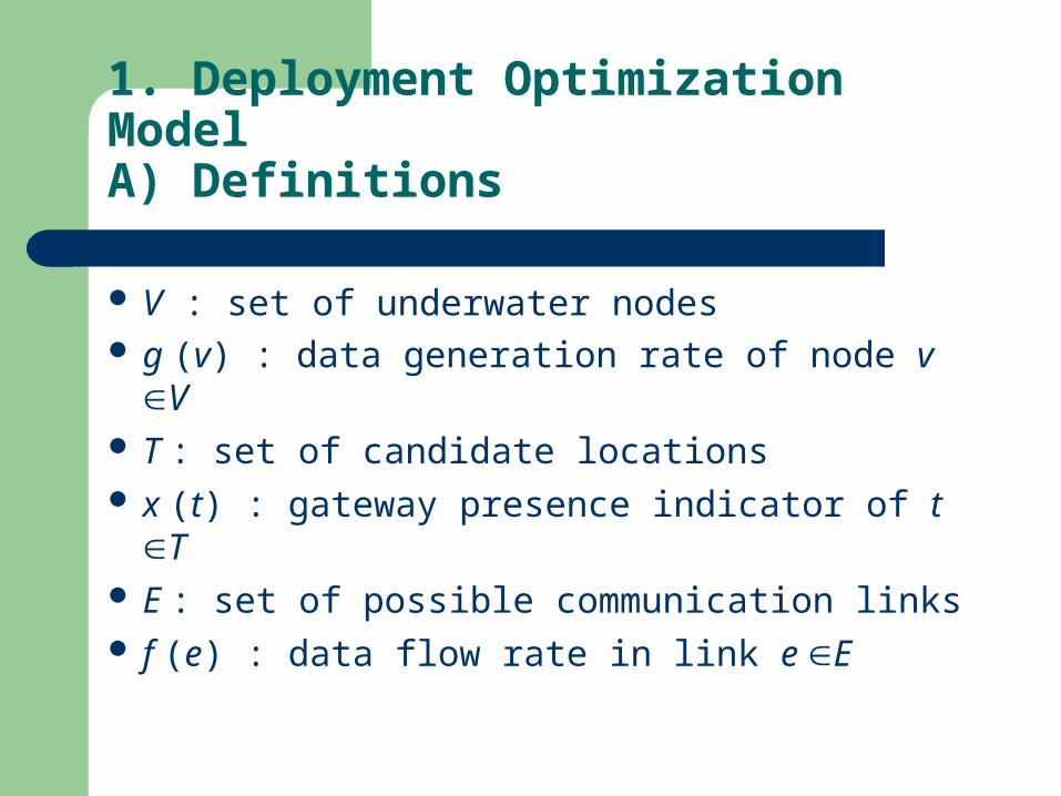
V : set of underwater nodes g (v) : data generation rate of node v V T : set of candidate locations x (t) : gateway presence indicator of t T E : set of possible communication links f (e) : data flow rate in link e E
1. Deployment Optimization ModelA) Definitions
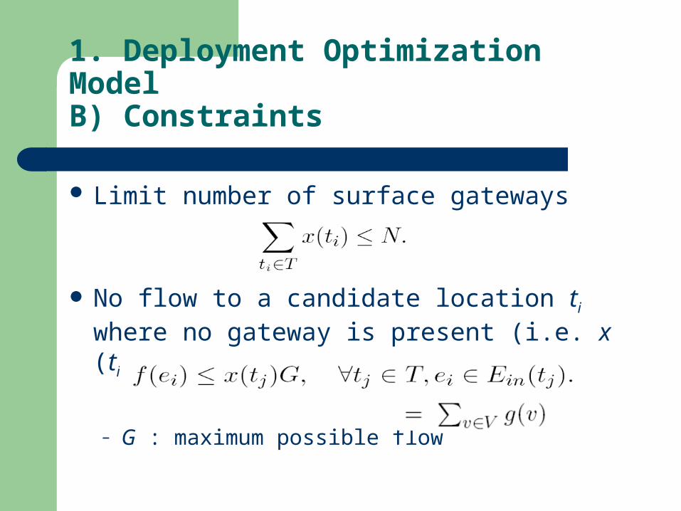
Limit number of surface gateways
No flow to a candidate location ti where no gateway is present (i.e. x (ti)=0)
– G : maximum possible flow
1. Deployment Optimization ModelB) Constraints
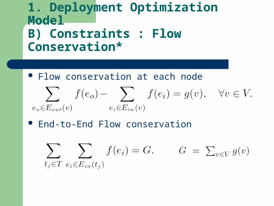
1. Deployment Optimization ModelB) Constraints : Flow Conservation*
Flow conservation at each node
End-to-End Flow conservation
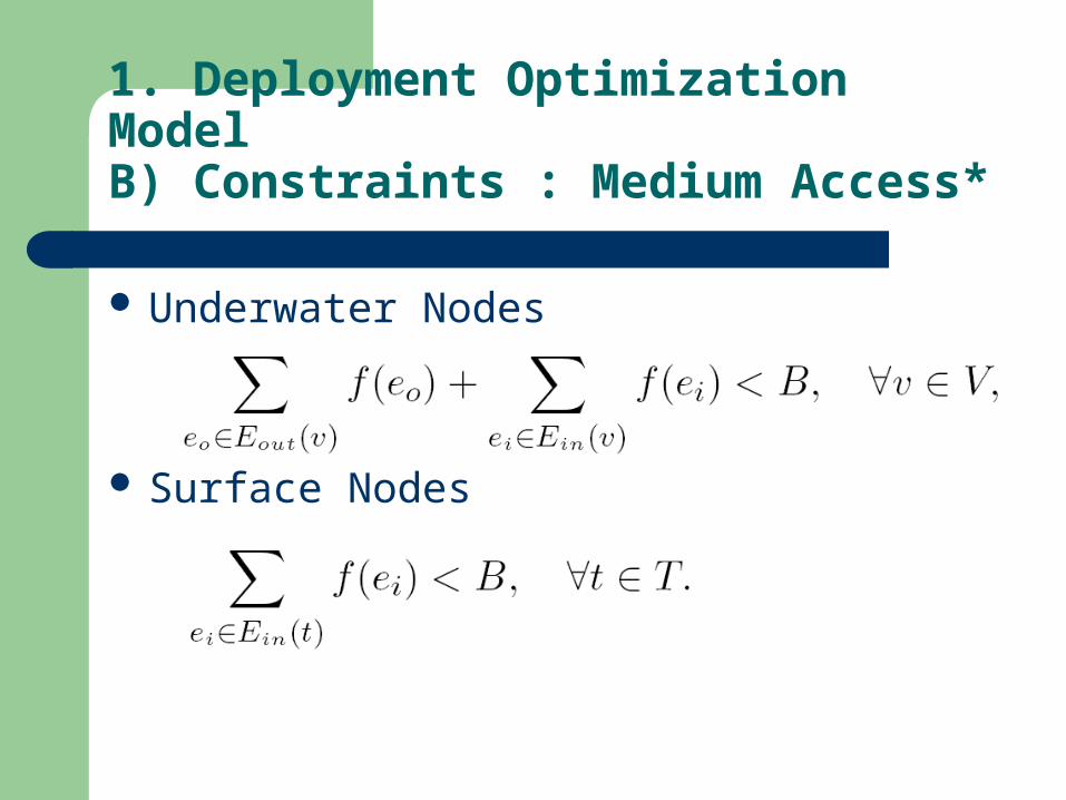
Underwater Nodes
Surface Nodes
1. Deployment Optimization ModelB) Constraints : Medium Access*

Delay d of Edge e
– L message length, B bit-rate, l(e) distance, vp propagation velocity.
Minimize expected end-to-end delay
– Minimize
1. Deployment Optimization ModelC) Objective : Minimize Expected Delay
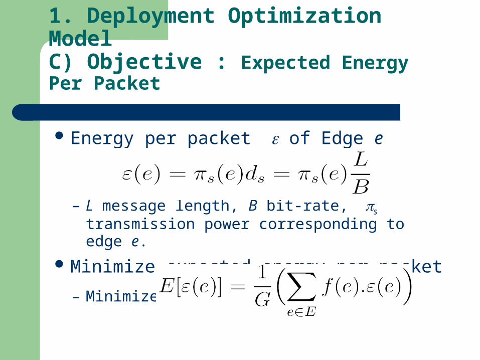
Energy per packet of Edge e
– L message length, B bit-rate, s transmission power corresponding to edge e.
Minimize expected energy per packet
– Minimize
1. Deployment Optimization ModelC) Objective : Expected Energy Per Packet
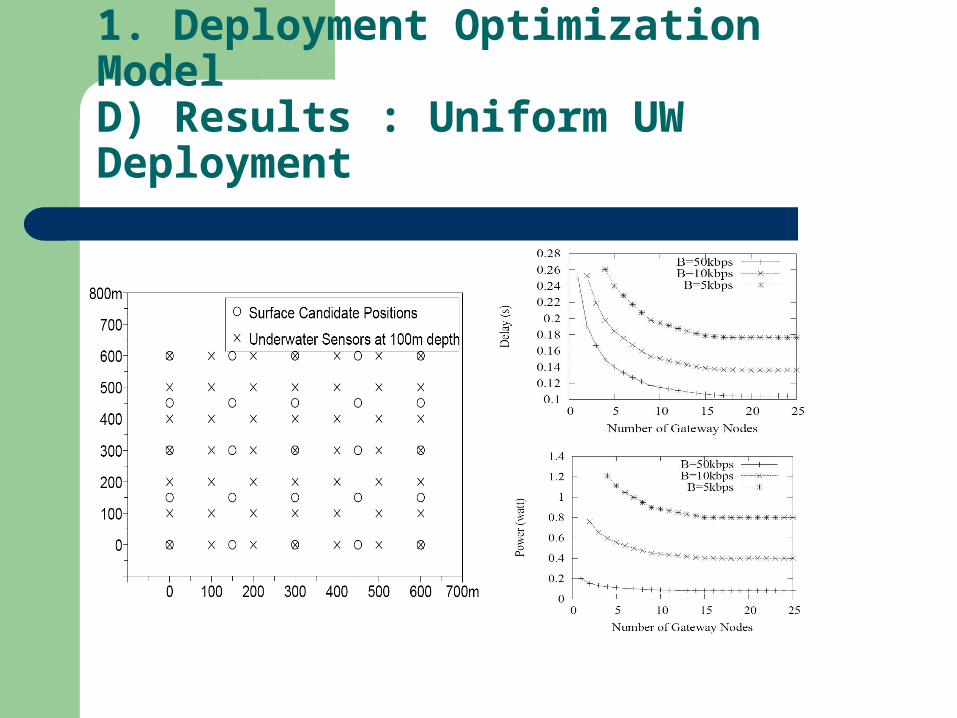
1. Deployment Optimization ModelD) Results : Uniform UW Deployment
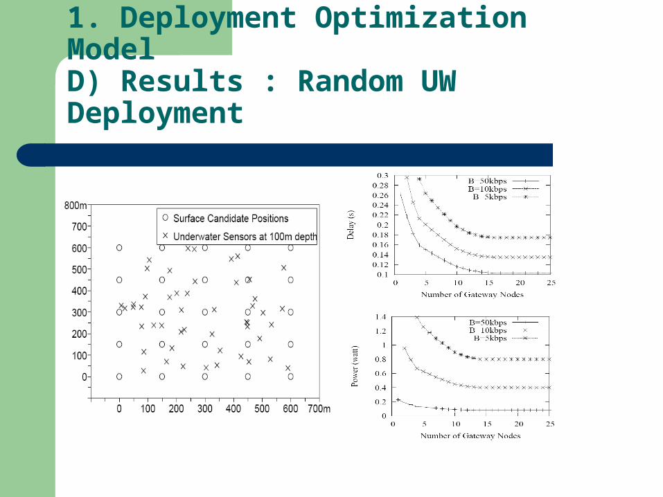
1. Deployment Optimization ModelD) Results : Random UW Deployment
2. Evaluation of Greedy Heuristics
Problem:– ILP is NP-hard
Proposed Solution– Greedy algorithm– Greedy-interchange algorithm
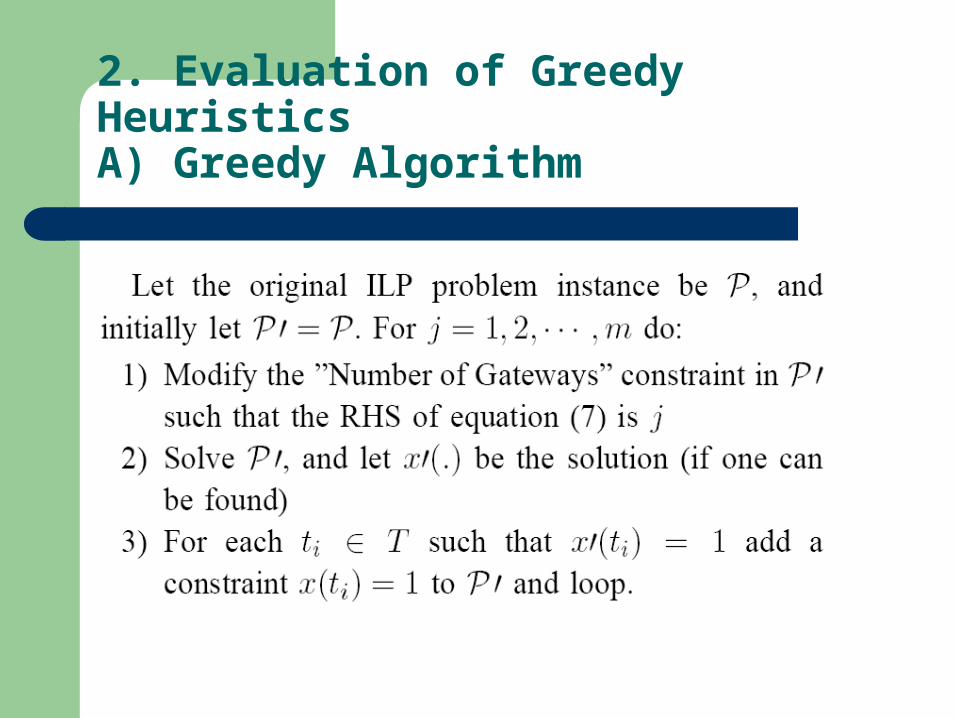
2. Evaluation of Greedy HeuristicsA) Greedy Algorithm
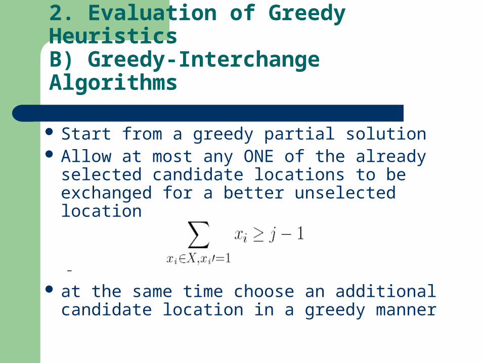
2. Evaluation of Greedy HeuristicsB) Greedy-Interchange Algorithms
Start from a greedy partial solution Allow at most any ONE of the already selected
candidate locations to be exchanged for a better unselected location
– at the same time choose an additional
candidate location in a greedy manner

2. Evaluation of Greedy HeuristicsC) Complexity Analysis
Define k:– the upper bound on the runtime of the network
optimization algorithm that calculates the value of the objective function for a given deployment
Optimal
Greedy
Greedy-Interchange

2. Evaluation of Greedy HeuristicsD) Evaluation Technique
Reference Deployment Techniques– Random
Pick the gateway candidate locations at random
– Optimal Solve the ILP
Test Cases– Uniform underwater deployment – Random underwater deployments
Measure the decay in optimization goal– Increase in delay

2. Evaluation of Greedy HeuristicsD) Results : Uniform UW Deployment
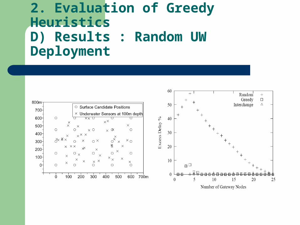
2. Evaluation of Greedy HeuristicsD) Results : Random UW Deployment
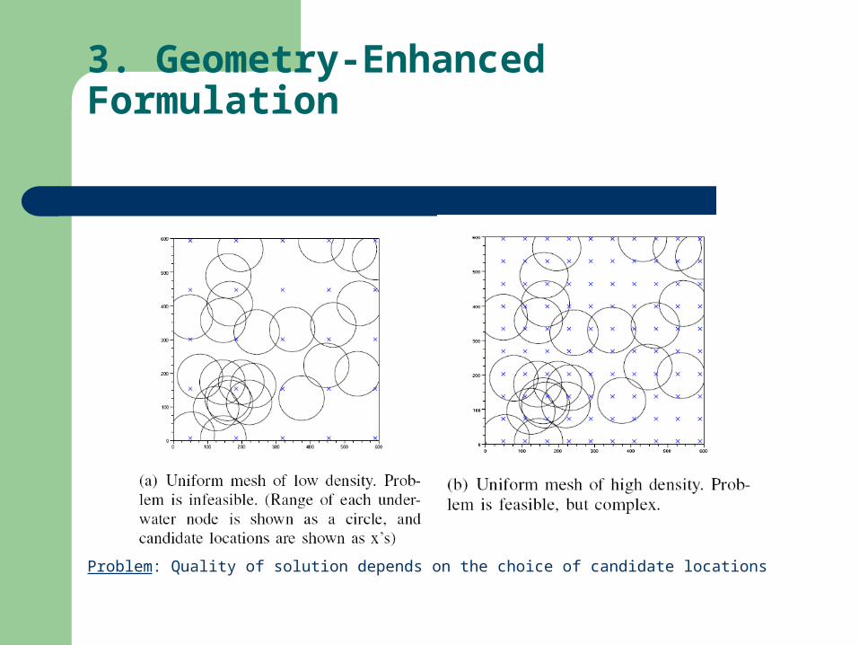
3. Geometry-Enhanced Formulation
Problem: Quality of solution depends on the choice of candidate locations

3. Geometry-Enhanced FormulationB) Algorithm
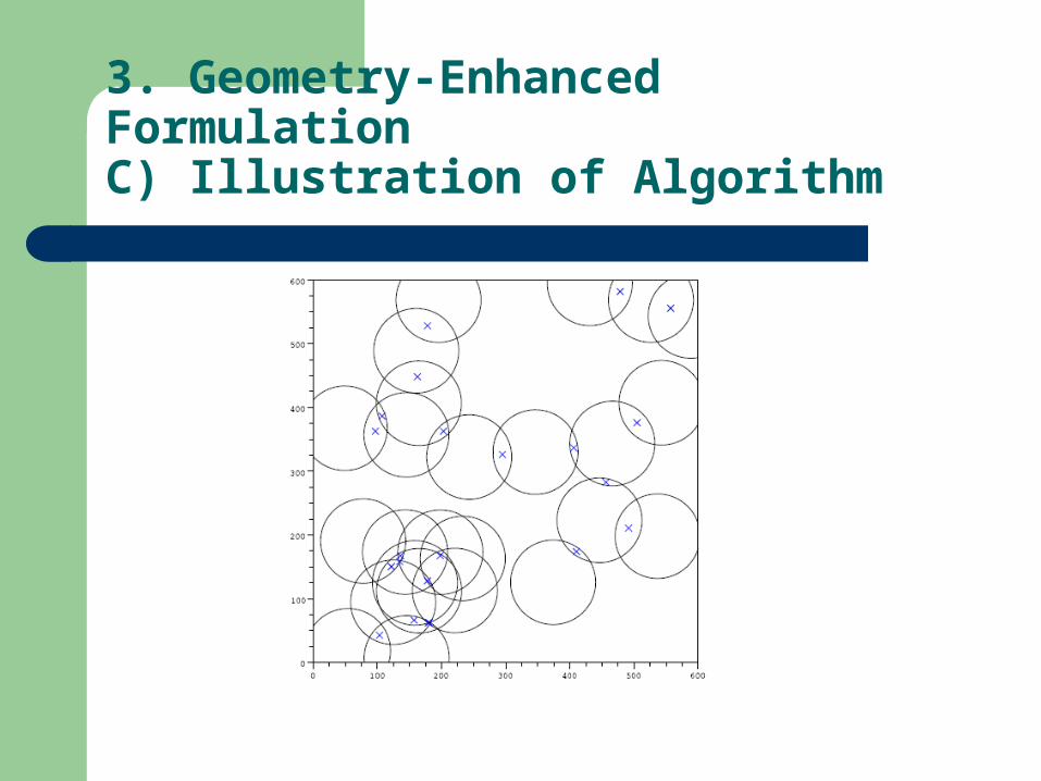
3. Geometry-Enhanced FormulationC) Illustration of Algorithm
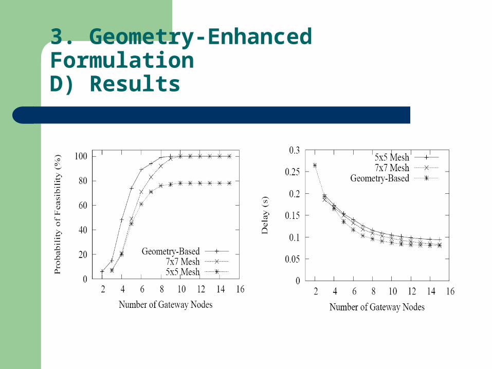
3. Geometry-Enhanced FormulationD) Results

Thank you