Embed Size (px)
Citation preview
HEADQUARTERSDEPARTMENT OF THE ARMY
FM 3-35.4 (100-17-4)18 June 2002
DEPLOYMENT FORT-TO-PORT
DISTRIBUTION RESTRICTION:Approved for public release; distribution is unlimited.

Distribution Restriction. Approved for public release; distribution is unlimited. i
Field Manual No. 3-35.4 (100-17-4)
FM 3-35.4 (100-17-4) Headquarters
Department of the Army Washington, DC, 18 June 2002
DEPLOYMENT FORT-TO-PORT
Contents Page
Preface................................................................................................................ iv
Introduction......................................................................................................... v
CHAPTER 1 DEPLOYMENT: FORT-TO-PORT - AN OVERVIEW .......................................1-1 Section I – Force Projection ...........................................................................1-1 Section II - Deployment...................................................................................1-3
Deployment Phases....................................................................................1-4 The Deployment Process............................................................................1-5
Section III - Principles Governing Predeployment Activities and Fort-To-Port Movement ....................................................................................1-6
Section IV - Joint Deployment Information System Improvement .............1-7 Section V – The Army Transformation and Deployment .............................1-9
Chapter 2 PREDEPLOYMENT ACTIVITIES .....................................................................2-1 Section I - Planning and Preparation.............................................................2-2
Planning Process ........................................................................................2-2 Joint Operation Planning and Execution System (JOPES) ........................2-3 Deployment Plans and Procedures ............................................................2-7 Battle Books................................................................................................2-8 Route and Location Reconnaissance and Rehearsal ................................2-8
Section II – Deployment Training Requirements .........................................2-9 Collective Training ......................................................................................2-9 Installation Training...................................................................................2-10 Individual Soldier Training.........................................................................2-10 Unit Movement Officer (UMO) ..................................................................2-11 Unit Loading Teams..................................................................................2-11 Air Load Planners .....................................................................................2-12 Hazardous Cargo Certifying Official .........................................................2-12 Mission Specific Training ..........................................................................2-13
Chapter 3 INSTALLATION ACTIVITIES ...........................................................................3-1 Section I - Installation Predeployment Activities .........................................3-2
Installation Staging Area (ISA)....................................................................3-2 Rail Preparation/Operations .......................................................................3-3
FM 3-35.4 _________________________________________________________________________________
ii
Soldier Readiness Processing (SRP) ........................................................ 3-4 Personal Property....................................................................................... 3-5 Family Members ......................................................................................... 3-5 Individual Clothing and Equipment Inspection ........................................... 3-5 Overseas Orientation ................................................................................. 3-6 Clearance from the Installation................................................................... 3-6 Maintenance ............................................................................................... 3-6 Deploying DA Civilians and Contractors .................................................... 3-7 Rear Detachment ....................................................................................... 3-7 Security....................................................................................................... 3-8
Section II – Organization Responsibilites .................................................... 3-8 Emergency Operations Center (EOC) ....................................................... 3-8 Installation Transportation Officer (ITO)..................................................... 3-9 Deployment Support Brigades (DSB) ........................................................ 3-9 CONUS Replacement Center (CRC) ....................................................... 3-10 Deployment Processing Center (DPC) .................................................... 3-10
Section III – Force Protection/Antiterrorism .............................................. 3-11
Chapter 4 MOVEMENT TO AND ACTIVITIES AT PORTS OF EMBARKATION ............ 4-1 Section I – Principles of Movement............................................................... 4-2
Principles .................................................................................................... 4-2 Liaison Officer............................................................................................. 4-2
Section II – Fort-to-Port Movement ............................................................... 4-3 Convoy Operations..................................................................................... 4-3 Rail Operations........................................................................................... 4-4
Section III – Activities at the Ports of Embarkation..................................... 4-4 Seaports ..................................................................................................... 4-4 Military Traffic Management Command ..................................................... 4-4 MTMC Deployment Support Team............................................................. 4-5 Transportation TerminaL Brigade............................................................... 4-5 Military Sealift Command............................................................................ 4-6 U.S. Coast Guard ....................................................................................... 4-6 Port Support Activity ................................................................................... 4-7 Supercargo ................................................................................................. 4-8 Port Operations Center .............................................................................. 4-8 Support Installations ................................................................................... 4-8 Deploying Unit ............................................................................................ 4-9 Marshaling Areas........................................................................................ 4-9 Staging Areas ........................................................................................... 4-10 Airports ..................................................................................................... 4-11 Railhead ................................................................................................... 4-15
Chapter 5 FORT-TO-PORT IN-TRANSIT VISIBILITY ...................................................... 5-1 Section I – Planning Considerations and Responsibilities ........................ 5-2
Automated Information Systems/Automatic Identification Technology and In-Transit Visibility (AIS/AIT and ITV) ........................................... 5-2
Major Army Command................................................................................ 5-2 United States Army Reserve ...................................................................... 5-3 Major Subordinate Command/Installation .................................................. 5-3 Installation Deployment Information Network............................................. 5-5 Brigade Equivalent ..................................................................................... 5-8 Battalion and Separate Company/Unit ....................................................... 5-8
_________________________________________________________________________________FM 3-35.4
iii
Section II – Installation Support En Route to the POE ................................5-9 Section III – Aerial Ports of Embarkation ....................................................5-10
AIS Planning Considerations at the APOE...............................................5-10 Passenger Movements Through an APOE ..............................................5-11 Unit Equipment Movements Through an APOE .......................................5-12
SECTION IV – Seaports of Embarkation .....................................................5-14 AIS Planning Considerations at the SPOE...............................................5-14 Cargo Movements Through a SPOE........................................................5-16 Passenger Movements Through a SPOE.................................................5-17
Appendix A AUTOMATION AND COMMUNICATION SYSTEMS ..................................... A-1
Appendix B TIME-PHASED FORCE AND DEPLOYMENT DATA (TPFDD) DEVELOPMENT .............................................................................................. B-1
Appendix C DEPLOYMENT BINDERS ............................................................................... C-1
Appendix D DEPLOYMENT PLANNING............................................................................. D-1
Appendix E UNIT MOVEMENT PLAN (SAMPLE) .............................................................. E-1
Appendix F UNIT AIRLIFT AFFILIATION PROGRAM ........................................................F-1
Appendix G HAZARDOUS CARGO ....................................................................................G-1
Appendix H RAIL OPERATIONS ........................................................................................ H-1
Appendix I CLASSIFIED AND SENSITIVE CARGO ...........................................................I-1
Appendix J CONVOY COMMANDER'S CHECKLIST......................................................... J-1
Appendix K THE JOINT INSPECTION PROCESS ............................................................. K-1
Appendix L DEPLOYING UNIT DEPARTURE AIRFIELD CONTROL GROUP PLANNING AND PREPARATION PHASE REQUIREMENTS........................L-1
Appendix M LABELING AND TAGGING EQUIPMENT ......................................................M-1
Glossary .............................................................................................................. Glossary-1
Bibliography ........................................................................................................Bibliography-1
Index .................................................................................................................... Index-1
FM 3-35.4 _________________________________________________________________________________
iv
Preface This manual defines deployment in terms of its process, structure, and organization from the point of origin or home station (HS) to the port of embarkation (POE). It recognizes the shift in U.S. strategic policy from forward presence to power projection and the resulting reliance on the strategic mobility triad to fulfill the U.S. Army requirements for force projection.
This manual's focus is on planning for and execution of deployments in a joint arena to satisfy Joint Operation Planning and Execution System (JOPES) process requirements. It concentrates on the sequence of actions and requirements for both the deploying unit and agencies responsi-ble for its deployment from origin/mobilization station to the ports of embarkation (POEs) (fort-to-port).
This manual supports soldiers, leaders, and staffs who execute deployment operations, specifi-cally at the Army service component command (ASCC)/Army forces (ARFOR), deploying unit, in-stallation, and supporting unit levels. Roles and missions of other agencies instrumental in the deployment process are described to aid the primary players in their understanding of the entire force projection sequence.
The proponent of this manual is the U.S. Army Training and Doctrine Command. Send com-ments and recommendations on DA Form 2028 directly to Commander, U.S. Army Combined Arms Support Command, Directorate of Combat Developments for Combat Service Support, ATTN: ATCL-C, Fort Lee, VA, 23801-1809.
Unless this publication states otherwise, masculine nouns or pronouns do not refer exclusively to men.
_________________________________________________________________________________FM 3-35.4
v
Introduction
"...power projection, enabled by overseas presence, will likely remain the fundamental strategic concept of our future force."
Joint Vision 2010
Smaller Army forces with fewer of them forward-deployed require an Army that is prepared to deploy anywhere in the world on short notice from both the continental United States (CONUS) and forward-deployed locations outside CONUS (OCONUS). The United States Army is the na-tion’s strategic land force and the strategic core of U.S. forces for joint or multinational opera-tions. While it is the world’s premier land force, the Army’s relevance depends on being strategi-cally responsive, for example, its ability to deliver early and continuous lethal combat power through force projection. The Army's defining strategy has become one of having tailored, lethal, decisive forces, capable of deploying quickly to any global hotspot. Force projection is not a new mission for the Army, but profound changes in force structure, sta-tioning, and world situation have raised it to a preeminent mission and changed its operational nature. The Army has to move with a greater velocity and sustained lethality to fulfill its role as the guarantor of victory. The previous operational rhythm of halt, buildup, and counterattack is no longer acceptable for force projection operations. Future enemies will not allow an incre-mental build up of combat power. Moreover, a future adversary’s exploitation of technology, weapons of mass destruction, and asymmetrical anti-access measures, coupled with the natural friction points in the constrictive force projection pipeline, will make force projection a more chal-lenging and difficult operation. This manual explains the United States Army’s responsibilities in force projection to better pre-pare the key organizations involved in deployment: the ASCC/ARFOR, the deploying unit, the installation, and the supporting units. The ARFOR could vary in size from multiple corps to a battalion, depending upon the mission. The responsibilities and planning involved in the process of deployment entail similar actions whatever the command level. In austere theaters, the de-ployment enabling systems (software and communications) may be unavailable; however, this manual discusses these systems because units deploying from power projection platforms (PPPs) or power support platforms (PSPs) will eventually have state-of-the-art infrastructure and automation support. In addition to planning considerations, this manual presents the deployment process from verbal warning through port of embarkation operations. It describes operations at both seaports of em-barkation and aerial ports of embarkation. This manual is one in a series dealing with force projection stemming from the capstone FM 3-35 (100-17). In this series, FM 3-35.1 (100-17-1) establishes the doctrinal framework for a pre-designated heavy brigade drawing Army pre-positioned stocks from forward-based ships. FM 3-35.2 (100-17-2) describes similar procedures from land sites in certain theaters. FM 3-35.3 (100-17-3) defines actions from the ports of debarkation to tactical assembly areas or to operational destinations. FM 3-35.5 (100-17-5) on redeployment completes the series. Since these publica-tions adequately amplify these specific operations, this manual focuses on the Army’s primary responsibility of planning for and moving a unit from origin/mobilization station to the ports of embarkation (POEs) and the subsequent requirements at the ports to ensure a successful de-ployment. Detailed tactics, techniques, and procedures on unit responsibilities in deployment will be pub-lished in FM 4-01.011 (55-65).

1-1
Contents
Section I – Force Projection 1-1 Section II - Deployment 1-3
Deployment Phases 1-4 The Deployment Process 1-5
Deployment Planning 1-5 Section III – Principles Governing Predeployment
Activities and Fort-to-Port Movement 1-6 Section IV - Joint Deployment Information
System Improvement 1-7 Section V – The Army Transformation and Deployment 1-9
Chapter 1
Deployment: Fort-to-Port—an Overview
"The deployment of land forces is the gravest response that can be made, short of war, to demonstrate the national will to prevent conflict."
Army Vision 2010
Force projection, a military element of national power, sys-tematically and rapidly moves military forces in response to requirements of war or military operations other than war (MOOTW). It demonstrates the ability to alert, mobilize, deploy rapidly, and operate effectively anywhere in the world. The U.S. Army, as a key member of the joint team, must be ready for global force projection with an appropriate mix of combat, combat support, and combat service support forces. It can execute a variety of missions spanning the range of military operations. More importantly, the world situation demands that the Army project its first-rate power at an unprecedented pace and accomplish diffi-cult missions that promise to be more complex than those of the past.
Army Goal: "With the right technological solutions...allow U.S. to put a combat capable brigade anywhere in the world in 96 hours after liftoff, a division on the ground in 120 hours, and five divisions in 30 days."
General Shinseki, CSA
SECTION I – FORCE PROJECTION
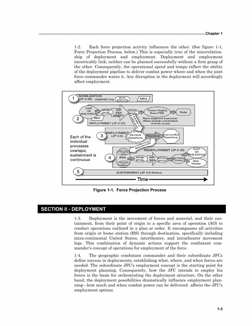
1-1. Force projection operations encompass a range of processes that occur in a continuous, overlapping, and iterative sequence. These activities include: • Mobilization. Mobilization is the process of assembling and organizing
national resources to support national objectives in time of war (and for MOOTW) or other emergencies. Each Service maintains its own mobili-zation plan and planning system. Mobilization includes bringing all or part of the industrial base and the armed forces of the United States to the necessary state of readiness to meet the requirements of the specific contingency. Mobilization may include activation of all, or part, of the
FM 3-35.4 _________________________________________________________________________________
1-2
United States Army Reserve (USAR), as well as assembling and organiz-ing personnel, supplies, and materiel. Once assembled, personnel will undergo predeployment checks and training as needed.
• Deployment. Deployment is movement of forces and their sustainment from their point of origin to a specific operational area to conduct joint operations outlined in a given plan or order. The type and nature of de-ployments vary widely according to scenario and circumstances. Occas-sionally, strategic deployment may involve the intertheater movement of forces and materiel using national and allied and/or coalition deployment capabilities
• Employment. Employment prescribes how to apply force and/or forces to attain specified national strategic objectives. During the planning proc-ess, the joint forces commanders (JFCs) and their component commands develop employment concepts. These concepts provide the foundation and determine the scope of mobilization, deployment, sustainment, and rede-ployment processes. Employment encompasses a wide array of operations including, but not limited to, entry operations (opposed or non-opposed), decisive operations (combat or support), and post-conflict operations (pre-pare for redeployment or for follow-on mission).
• Sustainment. Sustainment is directed toward providing and maintaining levels of personnel and materiel required to sustain the levels of combat or mission activity for the appropriate duration and at the desired level of intensity. Sustainment is ongoing throughout the entire process of de-ployment and redeployment. Key decisions made early in force projection operations concern basing and sustaining the force. Force projection op-erations may involve the establishment of support facilities in multiple sites outside the continental United States (OCONUS), including the cri-sis area. Logistic support will usually be split-based between several theaters and the continental United States (CONUS). The location and size of the base or bases supporting the operation is a key factor in opera-tional reach. CONUS bases supporting a deployment or redeployment will normally be selected or designated by the Services and Defense agencies participating in the operation in consultation with United States Transportation Command (USTRANSCOM) or its component commands. Supporting combatant commanders will select bases within their theaters to support a specific operation. The supported combatant commander will select or designate theater bases to support the joint re-ception, staging, onward movement, and integration (JRSOI) of arriving forces.
• Redeployment. Redeployment involves the transfer of units, individuals, or supplies deployed in one area to another location within the area, to the zone of interior for the purpose of further employment. Also, to CONUS and/or OCONUS home and/or demobilization stations for the purpose of further operational employment or demobilization. Post-conflict missions may affect the redeployment flow. Commanders (CDRs) must plan and execute redeployment in a manner that optimizes the readiness of redeploying forces and materiel to meet new contingencies or crisis.
_________________________________________________________________________________Chapter 1
1-3
1-2. Each force projection activity influences the other. (See figure 1-1, Force Projection Process, below.) This is especially true of the interrelation-ship of deployment and employment. Deployment and employment inextricably link; neither can be planned successfully without a firm grasp of the other. Consequently, the operational speed and tempo reflect the ability of the deployment pipeline to deliver combat power where and when the joint force commander wants it. Any disruption in the deployment will accordingly affect employment.
Figure 1-1. Force Projection Process
SECTION II - DEPLOYMENT
1-3. Deployment is the movement of forces and materiel, and their sus-tainment, from their point of origin to a specific area of operation (AO) to conduct operations outlined in a plan or order. It encompasses all activities from origin or home station (HS) through destination, specifically including intra-continental United States, intertheater, and intratheater movement legs. This combination of dynamic actions support the combatant com-mander’s concept of operations for employment of the force.
1-4. The geographic combatant commander and their subordinate JFCs define success in deployments, establishing what, where, and when forces are needed. The subordinate JFC's employment concept is the starting point for deployment planning. Consequently, how the JFC intends to employ his forces is the basis for orchestrating the deployment structure. On the other hand, the deployment possibilities dramatically influence employment plan-ning—how much and when combat power can be delivered affects the JFC's employment options.
FM 3-35.4 _________________________________________________________________________________
1-4
1-5. The commander of the Army service component command (COMASCC) assigned to the geographical combatant commander, in concert with subordinate Army force commanders, take the subordinate JFC em-ployment concept and develop the Army force plan. The COMASCC tailors the Army forces (ARFOR) to meet the subordinate JFC’s deployment and employment requirements. The commander of the Army service component command identifies the ARFOR in the development and refinement of the time-phased force and deployment data (TPFDD). See field manual (FM) 3-93 (100-7), and FM 3-35 (100-17) for further discussion on the Army service component command (ASCC).
DEPLOYMENT PHASES 1-6. Deployments consist of four distinct and interrelated deployment phases. These phases may not be sequential and could overlap or occur simultaneously: • Predeployment activities • Movement to and activities at the port of embarkation (POE) — fort-to-
port • Movement to port of debarkation (POD) — port-to-port • Reception, staging, onward movement, and integration (RSO&I) — port-
to-destination
1-7. The friction that develops as soldiers and equipment move through the lines of communication (LOCs) at forts, ports, and tactical assembly areas (TAAs) slows the arrival of combat power in the theater. It also lessens the efficiency and effectiveness of the total mobility system. In addition, time wasted in any phase affects force closure. A successful deployment requires smooth and quick implementation of each phase and seamless transitions or interactions between them all.
1-8. The effectiveness and/or inefficiency of the first two phases, which are the focus of this publication, set the conditions for the rest of the deploy-ment. Several principles guide commanders to execute predeployment activi-ties and the fort-to-port movement effectively and efficiently. Section III of this chapter discusses these principles.
1-9. JP 4-01 discusses the defense transportation system (DTS) employed in the third phase. The fourth phase overlaps with the entry stage of a force projection operation. FM 3-35.3 (100-17-3) covers this component for the Army. Joint Publication (JP) 4-01.8 is the joint manual on the subject.
1-10. A multitude of manuals, including FMs 3-0 (100-5), 3-93 (100-7), 3-100.15 (100-15), and 3-100.71 (71-100), discuss employment. FM 4-0 (100-10) and subordinate combat service support (CSS) manuals detail how the force is sustained throughout force projection operations. FM 3-35.5 (100-17-5) is the Army's primary doctrine on redeployment, while JP 3-35 is the relevant joint publication.
_________________________________________________________________________________Chapter 1
1-5
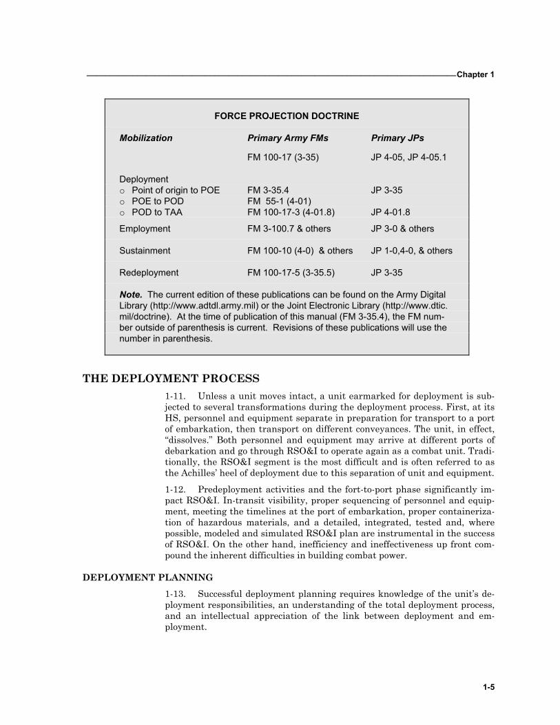
FORCE PROJECTION DOCTRINE
Mobilization Primary Army FMs Primary JPs
FM 100-17 (3-35) JP 4-05, JP 4-05.1
Deployment o Point of origin to POE FM 3-35.4 JP 3-35 o POE to POD FM 55-1 (4-01) o POD to TAA FM 100-17-3 (4-01.8) JP 4-01.8
Employment FM 3-100.7 & others JP 3-0 & others
Sustainment FM 100-10 (4-0) & others JP 1-0,4-0, & others
Redeployment FM 100-17-5 (3-35.5) JP 3-35
Note. The current edition of these publications can be found on the Army Digital Library (http://www.adtdl.army.mil) or the Joint Electronic Library (http://www.dtic. mil/doctrine). At the time of publication of this manual (FM 3-35.4), the FM num-ber outside of parenthesis is current. Revisions of these publications will use the number in parenthesis.
THE DEPLOYMENT PROCESS 1-11. Unless a unit moves intact, a unit earmarked for deployment is sub-jected to several transformations during the deployment process. First, at its HS, personnel and equipment separate in preparation for transport to a port of embarkation, then transport on different conveyances. The unit, in effect, “dissolves.” Both personnel and equipment may arrive at different ports of debarkation and go through RSO&I to operate again as a combat unit. Tradi-tionally, the RSO&I segment is the most difficult and is often referred to as the Achilles’ heel of deployment due to this separation of unit and equipment.
1-12. Predeployment activities and the fort-to-port phase significantly im-pact RSO&I. In-transit visibility, proper sequencing of personnel and equip-ment, meeting the timelines at the port of embarkation, proper containeriza-tion of hazardous materials, and a detailed, integrated, tested and, where possible, modeled and simulated RSO&I plan are instrumental in the success of RSO&I. On the other hand, inefficiency and ineffectiveness up front com-pound the inherent difficulties in building combat power.
DEPLOYMENT PLANNING 1-13. Successful deployment planning requires knowledge of the unit’s de-ployment responsibilities, an understanding of the total deployment process, and an intellectual appreciation of the link between deployment and em-ployment.
FM 3-35.4 _________________________________________________________________________________
1-6
1-14. Deployment planning is an invariable, logical process that focuses on soldiers and equipment for deployment, ways to deploy them and information and means to track them. In particular, deployment plans require specific in-formation (detail) to guide the unit through an effective deployment. The heart of deployment planning is a precise list of soldiers and equipment that have to deploy—the unit deployment list (UDL) (see next section for defini-tion), which is developed in the Transportation Coordinators’ Automated In-formation for Movement System II (TC-AIMS II). (See Appendix A.) Its im-portance exemplifies by its use, for example, to manifest unit equipment for deployment and to update the TPFDD so that appropriate lift is scheduled for the deployment.
1-15. The Army uses five steps in planning and preparation during pre-deployment activities: analyze mission, structure forces, refine deployment data, prepare the force, and schedule movement. Army commands from the ASCC and ARFOR through corps and division headquarters down to the de-ploying units execute each of these steps.
SECTION III - PRINCIPLES GOVERNING PREDEPLOYMENT ACTIVITIES AND FORT-TO-PORT MOVEMENT
Four principles apply to the broad range of activities encompassing pre-deployment and movement from fort-to-port: precision, synchronization, knowledge, and speed.
1-16. Precision applies to every activity and piece of data. Its effect is far-reaching, and the payoff is speed. Precise unit UDLs, for example, ensure that correct lift assets are quickly assigned against the requirement. Preci-sion in loading increases departure speed and safety. Precision in meeting the JFC's timeline supports his concept of employment. Current doctrine, re-alistic training, adequate support structure, and timely enablers, when work-ing synergetically, provide the framework for precision.
1-17. Just as a commander arranges activities in time and space to gain the desired effect during employment, so too should deployment activities be synchronized to close the force successfully. Resources such as lift assets, en-ablers, time, and information are scarce, and effective synchronization pro-duces maximum use of every resource. Synchronization normally requires explicit coordination among the deploying units and staffs, supporting units and staffs, a variety of civilian agencies, and other Services. Extensive exer-cises and training are the key to successful synchronization.
1-18. One of the more critical pieces at this stage of deployment is the knowledge upon which decisions are made. There is a short period of time during which the deploying commander must make crucial decisions on em-ployment. These decisions set the tone for the remainder of the deployment. Many of the decisions are irrevocable or very hard to change. For example, knowledge and understanding of the TPFDD are imperative to make deci-sions on high-priority items, sequencing, use of time, and prioritization. In addition, knowledge of the deployment process itself, as well as the require-
_________________________________________________________________________________Chapter 1
1-7
ments for effective predeployment activities and port-to-port movement, is a fundamental necessity.
1-19. Speed is more than miles per hour. The proper focus is on the velocity of the entire force projection process, from planning to force closure. In de-ployment, critical elements of force projection speed include the following fac-tors:
• Efficient planning tools.
• Agile ports.
• Submission of accurate information.
• Safe and efficient loading.
• Trained unit movement officers (UMOs).
• Timely arrival of throughput enablers.
• Maintaining unit integrity.
• Delivering capability rather than entire units.
I found the place crowded with an indiscriminate accumulation of supplies and war ma-teriel. The confusion...appeared to be utterly inextricable. The (rail) sidings from the port of Tampa for perhaps fifty miles into the interior were blocked with cars, the resulting dif-ficulties of the situation prevented proper embarkation of troops.
Nelson A. Miles Commanding General of the Army
1 June 1898
SECTION IV - JOINT DEPLOYMENT INFORMATION SYSTEM IMPROVEMENT
1-20. The Chairman of the Joint Chiefs of Staff (CJCS) has stated that re-cent improvements in strategic mobility capability must be complemented by improvements in the capability to conduct crisis action planning and execu-tion and to document the results. The key to this directive is improving the joint deployment and redeployment processes as Service-specific systems are phased out and one single integrated system is employed. Figure 1-2 charts the growth and phasing of the joint deployment information system im-provement process. It defines very clearly the move from Service-specific de-ployment systems, such as the Army’s Transportation Coordinator’s Auto-mated Command and Control Information System (TC-ACCIS) to TC-AIMS, which the CJCS designated as the single joint source data system for unit move information and the Joint Operation Planning and Execution System (JOPES). TC-AIMS II is the result of a joint effort of the U.S. Armed Forces and the Joint Project Management Office (JPMO), headed by the U.S. Army as the executive agent.
1-21. TC-AIMS II will exchange unclassified unit movement data files with the Joint Force Requirements Generator II (JFRG II). JFRG II will be the joint single source feeder system for unit move information from TC-AIMS II to JOPES. JFRG II will import classified TPFDD force records from JOPES,
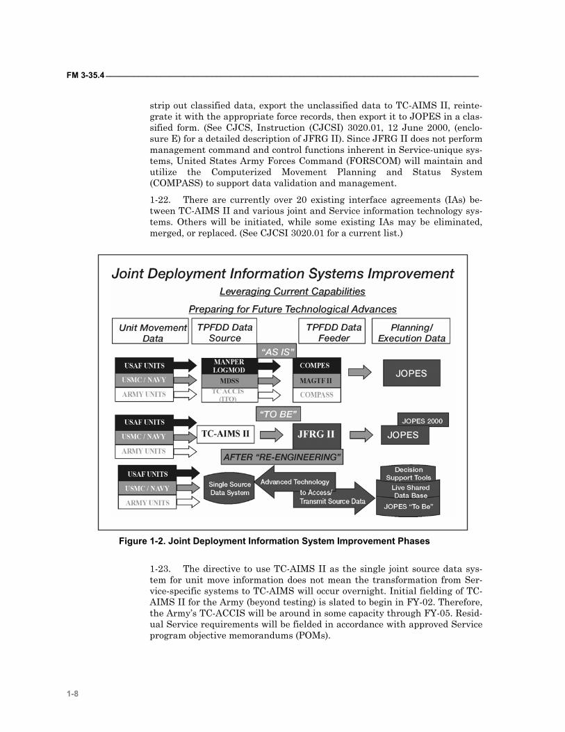
FM 3-35.4 _________________________________________________________________________________
1-8
strip out classified data, export the unclassified data to TC-AIMS II, reinte-grate it with the appropriate force records, then export it to JOPES in a clas-sified form. (See CJCS, Instruction (CJCSI) 3020.01, 12 June 2000, (enclo-sure E) for a detailed description of JFRG II). Since JFRG II does not perform management command and control functions inherent in Service-unique sys-tems, United States Army Forces Command (FORSCOM) will maintain and utilize the Computerized Movement Planning and Status System (COMPASS) to support data validation and management.
1-22. There are currently over 20 existing interface agreements (IAs) be-tween TC-AIMS II and various joint and Service information technology sys-tems. Others will be initiated, while some existing IAs may be eliminated, merged, or replaced. (See CJCSI 3020.01 for a current list.)
Figure 1-2. Joint Deployment Information System Improvement Phases
1-23. The directive to use TC-AIMS II as the single joint source data sys-tem for unit move information does not mean the transformation from Ser-vice-specific systems to TC-AIMS will occur overnight. Initial fielding of TC-AIMS II for the Army (beyond testing) is slated to begin in FY-02. Therefore, the Army’s TC-ACCIS will be around in some capacity through FY-05. Resid-ual Service requirements will be fielded in accordance with approved Service program objective memorandums (POMs).
_________________________________________________________________________________Chapter 1
1-9
1-24. As the force transitions from TC-ACCIS to TC-AIMS II, the terminol-ogy for use with the system also evolves. The automated unit equipment list (AUEL), a component of TC-ACCIS, becomes the organization equipment list (OEL) in TC-AIMS II. The deployment equipment list (DEL), another TC-ACCIS term, becomes the UDL in TC-AIMS II. For the sake of continuity, the new terms defined and described below will be utilized throughout the FM.
• Organizational Equipment List (OEL): The OEL (formally AUEL) is a computerized listing (in printed and data file formats) of on-hand equip-ment in a unit. The OEL supports cargo manifests for movement and provides input to transportation managers to identify movement re-quirements.
• Unit Deployment List (UDL): The UDL (formally DEL) is an OEL tai-lored for a specific or directed move. It lists the equipment that will actu-ally deploy.
SECTION V – THE ARMY TRANSFORMATION AND DEPLOYMENT
1-25. As a result of lessons learned from Operation Desert Storm, in Octo-ber 1999, the Chief of Staff Army (CSA) and the Secretary of the Army di-rected that the Army transform into a strategically responsive force that is dominant across the full spectrum of operations. Today, the Army is increas-ingly involved in stability and support operations (SASO) and small-scale contingency (SSC) situations in austere environments, while faced with the ultimate requirement for winning two near-simultaneous major regional con-flicts (MRC). To ensure the Army can respond to the situations above, the Army’s transformation begins with an initial effort in the Interim Force and moves to the Objective Force. • The Initial Force is the first effort of the Interim Force and begins with
two brigades organizing at Fort Lewis, Washington as off-the-shelf equipment is acquired. It evaluates and refines the operational and or-ganizational (O&O) concept, thereby establishing the critical conditions necessary to develop the Interim Force.
• The Interim Force is a transition force. It seeks the characteristics of the Objective Force to the maximum extent feasible, but leverages today’s state-of-the-art technology together with modernized legacy forces as a bridge to the future. It consists of five to eight interim brigade combat teams (IBCT).
• The Objective Force is the force that achieves the transformation objec-tive. It is a future force with a common design applied to the entire Army to achieve the force characteristics described in the Army Vision. (See the website http://www.army.mil/armyvision/default.htm.)
1-26. This transformation directive, known as the Army Transformation Campaign Plan states that the force must exhibit seven critical characteris-tics or imperatives in order to be better prepared for the future. The Army must be more— • Responsive. • Agile. • Versatile.
FM 3-35.4 _________________________________________________________________________________
1-10
• Lethal. • Survivable. • Sustainable. • Deployable.
1-27. The force must confront an adversary before setting the conditions in its favor to meet the deployable imperative. The Army’s objective is “to deploy a combat brigade force anywhere in the world in 96 hours, a division in 120 hours, and 5 divisions in 30 days.” The IBCT’s design capitalizes on the widespread use of common vehicular platforms, particularly a highly mobile, medium-weight combat/combat support platform, coupled with a minimiza-tion of personnel, a reduced logistics footprint, and state-of-the-art auto-mated information systems.
1-28. The phases for the deployment of the IBCT remain the same as those for other units, and the preparation processes discussed in subsequent chap-ters, (such as soldier readiness processing, training), also remain constant. However, for the IBCT to meet its mandated deployment timelines, prede-ployment activities must remain at a minimum and equipment and person-nel readiness rates should be maintained at 90 percent or greater. Efforts are being made during the development of the Objective Force to eliminate re-ception and staging in the theater. Extensive efforts at the HS and support installations (SI) will be required to ensure strategic transportation assets are loaded in such a way that deployed forces may begin operations immedi-ately upon arrival in the AO. (See FM 4-93.7 (63-7) for further information on deploying the IBCT).
2-1
CONTENTS Section I - Planning and Preparation 2-2
Planning Process 2-2 JOPES 2-3 Deployment Plans and Procedures 2-7 Battle Books 2-8 Route and Location Reconnaissance and Rehearsal 2-8
Section II – Deployment Training Requirements 2-9
Collective Training 2-9 Installation Training 2-10 Individual Soldier Training 2-10 Unit Movement Officer 2-11 Unit Loading Teams 2-11 Air Load Planners 2-12 Hazardous Cargo Certifying Official 2-12 Mission Specific Training 2-13
Chapter 2
Predeployment Activities
The Army’s challenge to become more strategically responsive begins at HS by increasing the efficiency and effectiveness of predeployment activities and fort-to-port movement. Speed, as measured by force closure, varies in almost all de-ployments. Factors influencing deployment speed include mis-sion, the combatant com-mander’s priorities, theater lo-cations, port capabilities, and other factors of mission, en-emy, terrain and weather, troops and support available, time available, civil considera-tions (METT-TC). It is advan-tageous to look at the deploy-ment segments and their influ-ence on force closure when ex-amining the reasons for the pace of a deployment.
Predeployment planning and the fort-to-port phase of deployment are activities that have the least amount of variance. Units follow set proce-dures to prepare and then move to the air or seaport of debarkation. The other phases, the port-to-port movement and RSO&I, are the most vari-able. Lift capabilities, port capabilities, and throughput factors all vary with the availability, distance, locations, and theater. The Army’s use of specified power projection platforms (PPPs) and designated ports de-creases the variables in fort-to-port operations, and increases the impact of training and knowledge.
FM3-35.4 _________________________________________________________________________________
2-2
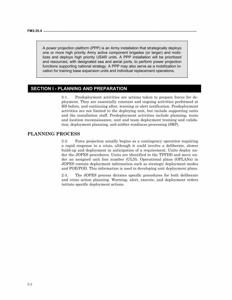
A power projection platform (PPP) is an Army installation that strategically deploys one or more high priority Army active component brigades (or larger) and mobi-lizes and deploys high priority USAR units. A PPP installation will be prioritized and resourced, with designated sea and aerial ports, to perform power projection functions supporting national strategy. A PPP may also serve as a mobilization lo-cation for training base expansion units and individual replacement operations.
SECTION I - PLANNING AND PREPARATION
2-1. Predeployment activities are actions taken to prepare forces for de-ployment. They are essentially constant and ongoing activities performed at HS before, and continuing after, warning or alert notification. Predeployment activities are not limited to the deploying unit, but include supporting units and the installation staff. Predeployment activities include planning, route and location reconnaissance, unit and team deployment training and valida-tion, deployment planning, and soldier readiness processing (SRP).
PLANNING PROCESS 2-2. Force projection usually begins as a contingency operation requiring a rapid response to a crisis, although it could involve a deliberate, slower build-up and deployment in anticipation of a requirement. Units deploy un-der the JOPES procedures. Units are identified in the TPFDD and move un-der an assigned unit line number (ULN). Operational plans (OPLANs) in JOPES contain deployment information such as strategic deployment modes and POE/POD. This information is used in developing unit deployment plans.
2-3. The JOPES process dictates specific procedures for both deliberate and crisis action planning. Warning, alert, execute, and deployment orders initiate specific deployment actions.
_________________________________________________________________________________Chapter 2
2-3
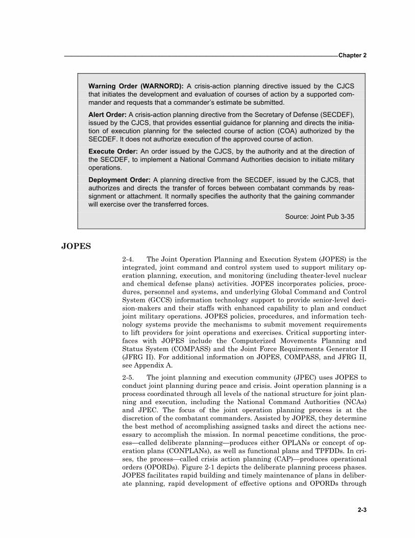
Warning Order (WARNORD): A crisis-action planning directive issued by the CJCS that initiates the development and evaluation of courses of action by a supported com-mander and requests that a commander’s estimate be submitted.
Alert Order: A crisis-action planning directive from the Secretary of Defense (SECDEF), issued by the CJCS, that provides essential guidance for planning and directs the initia-tion of execution planning for the selected course of action (COA) authorized by the SECDEF. It does not authorize execution of the approved course of action.
Execute Order: An order issued by the CJCS, by the authority and at the direction of the SECDEF, to implement a National Command Authorities decision to initiate military operations.
Deployment Order: A planning directive from the SECDEF, issued by the CJCS, that authorizes and directs the transfer of forces between combatant commands by reas-signment or attachment. It normally specifies the authority that the gaining commander will exercise over the transferred forces.
Source: Joint Pub 3-35
JOPES 2-4. The Joint Operation Planning and Execution System (JOPES) is the integrated, joint command and control system used to support military op-eration planning, execution, and monitoring (including theater-level nuclear and chemical defense plans) activities. JOPES incorporates policies, proce-dures, personnel and systems, and underlying Global Command and Control System (GCCS) information technology support to provide senior-level deci-sion-makers and their staffs with enhanced capability to plan and conduct joint military operations. JOPES policies, procedures, and information tech-nology systems provide the mechanisms to submit movement requirements to lift providers for joint operations and exercises. Critical supporting inter-faces with JOPES include the Computerized Movements Planning and Status System (COMPASS) and the Joint Force Requirements Generator II (JFRG II). For additional information on JOPES, COMPASS, and JFRG II, see Appendix A.
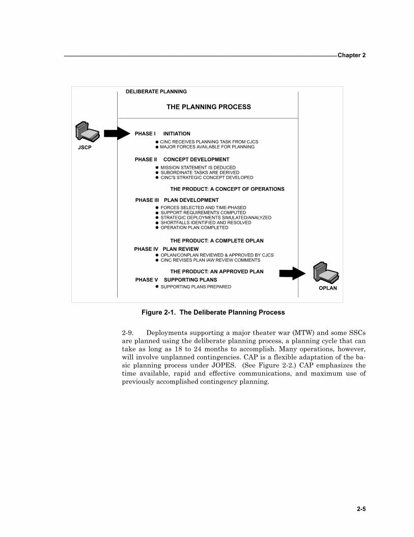
2-5. The joint planning and execution community (JPEC) uses JOPES to conduct joint planning during peace and crisis. Joint operation planning is a process coordinated through all levels of the national structure for joint plan-ning and execution, including the National Command Authorities (NCAs) and JPEC. The focus of the joint operation planning process is at the discretion of the combatant commanders. Assisted by JOPES, they determine the best method of accomplishing assigned tasks and direct the actions nec-essary to accomplish the mission. In normal peacetime conditions, the proc-ess—called deliberate planning—produces either OPLANs or concept of op-eration plans (CONPLANs), as well as functional plans and TPFDDs. In cri-ses, the process—called crisis action planning (CAP)—produces operational orders (OPORDs). Figure 2-1 depicts the deliberate planning process phases. JOPES facilitates rapid building and timely maintenance of plans in deliber-ate planning, rapid development of effective options and OPORDs through
FM3-35.4 _________________________________________________________________________________
2-4
adaptation of approved operation plans in no-plan situations in CAP, and ef-fective management of operations in execution across the spectrum of mobili-zation, deployment, employment, sustainment, and redeployment when op-erations are conducted. See Chairman, Joint Chiefs of Staff, Manuals, (CJCSMs) 3122.01 and 3122.03, CJCSI 3020.01, and JP 3-35 for a detailed description and instructions for use of JOPES.
2-6. The Commander, Army service component command (COMASCC) participates closely in the combatant commander’s deliberate planning proc-ess. The COMASCC must provide the ARFOR unit data, ARFOR support re-quirements, and the support capabilities required to meet the ARFOR’s Army-specific support requirements as well as the combatant commander’s designated lead Service common user logistics (CUL) requirements. As part of the process, the ASCC and subordinate commands help the deploying unit, installation, and supported geographical commander meet their individual responsibilities: • Monitor out-load and deployment preparations. • Coordinate with the installation for convoy requirements. • Ensure the unit deployment sequence is in accordance with the sup-
ported geographical commanders validated TPFDD requirements. • Advise the JPEC on progress. • Begin the force tracking process by transmitting data, such as departure
and arrival report and UDL updates, as required.
2-7. More information on ASCC planning requirements may be found in FM 3-93 (100-7).
2-8. USTRANSCOM analyzes transportation feasibility in conjunction with the supported combatant commander during the deliberate planning process. USTRANSOM conducts analysis using models, simulations, and transportation expertise. Dependable transportation feasibility analysis de-pends on accurate combatant command analysis of theater transportability.
_________________________________________________________________________________Chapter 2
2-5
Figure 2-1. The Deliberate Planning Process
2-9. Deployments supporting a major theater war (MTW) and some SSCs are planned using the deliberate planning process, a planning cycle that can take as long as 18 to 24 months to accomplish. Many operations, however, will involve unplanned contingencies. CAP is a flexible adaptation of the ba-sic planning process under JOPES. (See Figure 2-2.) CAP emphasizes the time available, rapid and effective communications, and maximum use of previously accomplished contingency planning.
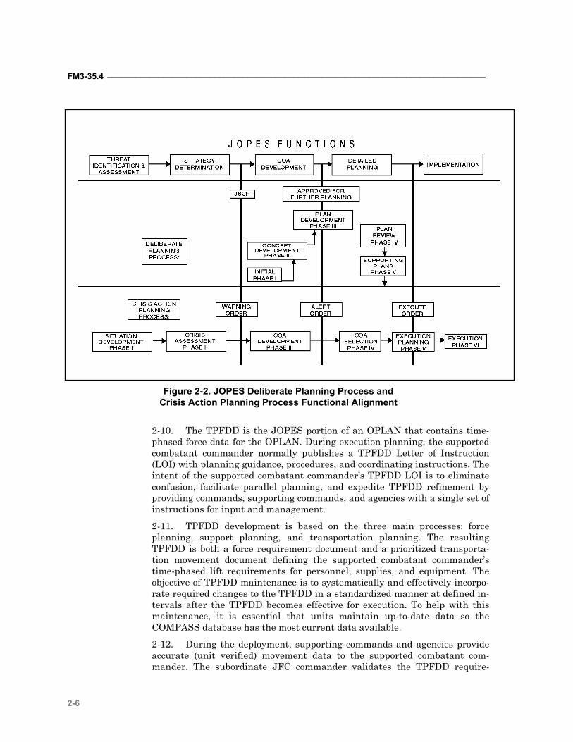
FM3-35.4 _________________________________________________________________________________
2-6
Figure 2-2. JOPES Deliberate Planning Process and Crisis Action Planning Process Functional Alignment
2-10. The TPFDD is the JOPES portion of an OPLAN that contains time-phased force data for the OPLAN. During execution planning, the supported combatant commander normally publishes a TPFDD Letter of Instruction (LOI) with planning guidance, procedures, and coordinating instructions. The intent of the supported combatant commander’s TPFDD LOI is to eliminate confusion, facilitate parallel planning, and expedite TPFDD refinement by providing commands, supporting commands, and agencies with a single set of instructions for input and management.
2-11. TPFDD development is based on the three main processes: force planning, support planning, and transportation planning. The resulting TPFDD is both a force requirement document and a prioritized transporta-tion movement document defining the supported combatant commander’s time-phased lift requirements for personnel, supplies, and equipment. The objective of TPFDD maintenance is to systematically and effectively incorpo-rate required changes to the TPFDD in a standardized manner at defined in-tervals after the TPFDD becomes effective for execution. To help with this maintenance, it is essential that units maintain up-to-date data so the COMPASS database has the most current data available.
2-12. During the deployment, supporting commands and agencies provide accurate (unit verified) movement data to the supported combatant com-mander. The subordinate JFC commander validates the TPFDD require-
_________________________________________________________________________________Chapter 2
2-7
ments of the supported combatant commander. The combatant commander then incorporates the JFC validation requirements with other theater valida-tion requirements already forwarded to USTRANSCOM and other lift pro-viders tasked with the mission to deploy forces and agencies that support the JFC. (As part of the TPFDD validation process, modeling and simulation of the flow of cargo, forces, and sustainment may be performed to identify pos-sible transportation/distribution shortfalls.) USTRANSCOM planners schedule movement consistent with the concept of operations.
2-13. TPFDD and movement schedule changes during deployment execu-tion are inevitable. Changes during deployment execution are often the re-sult of a change to the supported combatant commander’s priorities, deploy-ing unit missions, METT-TC, or incomplete or erroneous movement data in the TPFDD. Changes may also occur because of deployment planning deci-sions. Avoid TPFDD changes inside the validated window as they may affect the transportation flow. Management of changes is possible if changes are held to a minimum. They require supported combatant commander’s ap-proval.
2-14. Successful implementation of planning is critical for effective and timely deployment. The TPFDD is one of the most vital tools supporting this purpose. It sequences the activities of the deploying forces according to the supported subordinate JFC's concept of operations. It is common to all de-ployments. For more detailed information, see Appendix B.
2-15. The objective of deployment is the arrival of the force at the right place, at the right time, and in the right order. The TPFDD is, therefore, both a force requirements and a transportation requirements document, and it must be considered from both of these aspects. The supported subordinate JFC must approve any change to this statement of force requirements and priorities.
DEPLOYMENT PLANS AND PROCEDURES 2-16. To meet contingency support requirements, units develop deployment plans and standing operating procedures (SOPs). An effective deployment plan contains sufficient detail to prepare units to execute strategic deploy-ments. The unit deployment SOP is a generic document outlining functions that should occur automatically upon notification of a deployment. In addi-tion to deployment plans and SOPs, units often maintain deployment binders (see Appendix C) and battle books that contain deployment information and instructions.
"Commanders training together and knowing each other, rehearsing and practicing op-erations, holding AARs immediately after an exercise, refining and enforcing SOPs, and ensuring there is good understanding two levels up and down are a few of the things we need to emphasize."
Commander, 2ACR, Operation DESERT STORM
2-17. Deployment plans define responsibilities, functions, and details for each part of a unit deployment, from installation to reception in theater. There may be more than one deployment plan required depending on the
FM3-35.4 _________________________________________________________________________________
2-8
number of contingencies/OPLANs the unit must prepare to support. Deploy-ment plans are written in a five-paragraph OPORD format. They may con-tain SOPs, OELs, and other annexes as needed. The plans must be flexible enough to incorporate mission requirements and changes resulting from con-tingencies that have not been anticipated. (See Appendix D for a recom-mended process for developing deployment plans.)
2-18. The unit deployment SOP outlines functions that should occur auto-matically upon notification of a unit deployment. It should be generic to fit any given deployment situation. Day-to-day and alert functions should be in-cluded in the document. The SOP defines the duties of subordinate units/sections that will bring the unit to a higher state of readiness. These duties can be written in separate annexes, which can be easily separated and issued to leaders for execution. Functions addressed in the SOP may include unit property disposition, supply draw, equipment maintenance, vehicle and container loading, security, marshaling procedures, purchasing authorities, unit briefings, and other applicable deployment activities. FM to 55-15 Ap-pendix B provides a sample transportation SOP format. (FM 55-15 will be in-corporated into FM 4-01.011.)
2-19. For deployment preparation and execution, units may use a readiness standard of operation procedure (RSOP) or supplement their higher head-quarters RSOP/deployment SOP. The RSOP normally addresses the overall deployment concept, the notification hour (N-hour) sequence, force package training requirements, the alert notification system, logistics support, per-sonnel and equipment readiness, outload support (including SRP), and com-mand and control at critical points. This document is essential for the orderly execution of rapid force deployments in response to crisis situations.
2-20. Appendix D contains a deployment checklist for commanders to use to evaluate deployment readiness.
BATTLE BOOKS 2-21. The battle book has many names—deployment binder, smart book—but no matter what it is called, it documents how the commander accom-plishes his mission in the specified area of operations. It should include the organization and responsibilities for the unit’s RSO&I within the theater. The following specific deployment items should be included in the battle book, if applicable: • Pertinent information from the OPLAN and the TPFDD. • Information and photographs/schematics concerning the layout and fa-
cilities/capabilities of the ports of debarkation. • Maps of convoy routes within the AO, to include critical areas that the
unit will pass through en route to its employment location.
ROUTE AND LOCATION RECONNAISSANCE AND REHEARSAL 2-22. Reconnaissance of the route to pre-designated POEs and of the POEs themselves should be an ongoing activity. It may be accomplished through passive means such as map surveillance or, optimally, through site visits. Walking the terrain at the power projection platform and designated port fa-
_________________________________________________________________________________Chapter 2
2-9
cilities allows commanders to understand space limitation, see choke points, survey facilities, understand the simultaneous nature of the operation, and visualize the deployment operation. Terrain walks can be useful as a unit level activity, but are more beneficial when they involve all participating and supporting units.
2-23. Fort-to-port rehearsals are key to reducing deployment times. Units can use rehearsals as validation of their deployment plans. They permit commanders and unit movement officers to see possibilities and limitations. The physics of the operation can become plainly evident. A map reconnais-sance would not reveal that the staging area (SA) used in past operations is now is a shopping center, or that road construction that slowed traffic is now complete.
Conducting Rehearsals Orient participants. Define the standard. Visualize and synchronize the concept of the operation. Verbally walk through
the concept of the operation. Subordinate commanders should interactively verbalize their units actions, entering or leaving the discussion at the time they would expect to begin or end their task or activities. This will help the com-mander to assess the adequacy of synchronization.
Address any point of the operation where the execution of branches or se-quels is likely to occur.
If the standard is not met and time permits, rehearse again. Make changes.
SECTION II – DEPLOYMENT TRAINING REQUIREMENTS
2-24. Training is the underpinning mechanism to drive the Army’s effort intellectually to become strategically responsive. Unit deployment training is an essential element in developing the mental agility and knowledge re-quired for strategic responsiveness. Moreover, it is a proven way for units to increase the speed of projecting combat power.
2-25. Units train in peacetime to meet unit and individual training re-quirements for deployment operations. Force projection missions occur rap-idly, leaving the deploying unit with little or no time to correct training defi-ciencies or to meet mission specific training requirements.
COLLECTIVE TRAINING 2-26. Collective deployment training incorporates the knowledge, skills, attitudes, abilities, and the command emphasis so that deployment is a reflex activity executed with precision. Units must identify deployment as a mission essential task, annotate it on their mission essential task list (METL), and gain proficiency. Many Army training programs offer the opportunity to em-bed force projection training in a major training event program.
FM3-35.4 _________________________________________________________________________________
2-10
INSTALLATION TRAINING 2-27. Installation fort-to-port deployment activities are labor intensive and demanding in that they occur simultaneously. Effective fort-to-port deploy-ment activities rely on centralized planning and a decentralized execution base, according to the installation RSOP. Repetitive training is essential for success. Simultaneous actions include— • Establishing an emergency operation center (EOC). • Establishing rail and commercial truck operations. • Initiating a port support activity (PSA). • Initiating arrival/departure airfield control group (A/DACG) operations. • Establishing a convoy support center, if required. • Establishing port liaison teams. • Initiating automatic identification technology (AIT) plans.
INDIVIDUAL SOLDIER TRAINING 2-28. Units with deployment missions are required to have an appropriate number of personnel trained to perform special deployment duties. These du-ties include unit loading teams, hazardous cargo certifying officials, and air load planners. Each major command has specific requirements and policies for appointing and training personnel in these positions. In addition, many CONUS and OCONUS commands and installations maintain a capability lo-cally to provide deployment training. All deployable units, however, require personnel trained to perform the following deployment functions: UMO, unit loading team members, hazardous cargo certifying official and air load plan-ners.
2-29. Individual soldiers must accomplish, at a minimum, the following standardized Army training requirements before deployment: • An Army Physical Fitness Test (APFT) within the last 6 months. (A sol-
dier who has not successfully completed the APFT may still be deploy-able, subject to command review.)
• Code of conduct training within the last 12 months. • Survival, escape, resistance, and evasion (SERE) training peculiar to the
deployment destination. • Weapons qualification per AR 350-6 and DA Pam 350-38 within the last
12 months. • Subversion and espionage directed against the U.S. Army and deliberate
security violations (SAEDA) training within the past 12 months. • Law of War (Law of Armed Conflict) training within the past 12 months. • Driver's training for destination country. • Mobilization briefing. • Intelligence briefing. • Legal briefing. • Theater or mission specific training as defined by the supported combat-
ant commander.
_________________________________________________________________________________Chapter 2
2-11
UNIT MOVEMENT OFFICER 2-30. Preparing the unit for movement is the commander’s responsibility and the unit movement officer (UMO) is the commander’s appointed repre-sentative to assist in the accomplishment of this task. The UMO must know the unit’s mission and the commander’s intent when preparing the unit for deployment, so he can coordinate, plan, and execute appropriately. The UMO assembles and maintains unit movement plans and documentation, prepares the unit for movement, creates the unit’s equipment list, and supervises the outload of the unit.
2-31. The UMO must be familiar with Air Force and Army airlift opera-tions; the transportability of organic unit equipment; the characteristics and capabilities for the types of vessels, aircraft, or railcars the unit may use to deploy; and highway, rail, and port operations. FM 55-15, (to be incorporated into 4-01.011) is an excellent source for characteristics and capabilities of the various transportation assets (aircraft, railcars, and ships) and contains in-formation for planning mode operations. The UMO reference material for transportability of organic unit equipment can be found in Military Traffic Management Command Transportation Engineering Agency (MTMCTEA) Reference 700-5, and at the following website: www.tea.army.mil/dpe/FIELD.HTM. The UMO— • Prepares and maintains unit movement plans. (See Appendix E.) • Prepares and maintains the OEL and other documentation needed for
unit movements. • Prepares the UDL. • Changes and submits unit movement data (UMD) as required by the ma-
jor command (MACOM) and/or ASCC. • Supervises the preparation and execution of unit load plans. • Coordinates with higher headquarters and support activities on unit
movements. • Coordinates logistics support for the move. • Maintains approved copies of all unit load plans. • Establishes and trains unit loading teams. • Ensures the unit has access to personnel who are authorized to certify
hazardous material (HAZMAT) cargo.
UNIT LOADING TEAMS 2-32. Each unit is required to have an appropriate number of personnel trained in vehicle preparation and aircraft and rail loading/unloading tech-niques. Specific skills required include— • Preparing and activating vehicle load plans. • Preparing vehicles for shipment (purging, protecting fragile components,
weighing and marking for air and rail movement). • Executing aircraft and railcar tiedown procedures. • Loading and unloading unit vehicles on aircraft and railcars. • Palletizing cargo on 463L pallets.
FM3-35.4 _________________________________________________________________________________
2-12
2-33. Load team composition is tailored to the type and quantity of equip-ment to be loaded and the time available for loading. In general— • For rail movements, a well-trained team of five operators, using prefabri-
cated tiedown devices, can complete loading/lashing of equipment on a flatcar in approximately 15 minutes.
• For air movement, a six-person team can provide efficient loading and tiedown of equipment.
2-34. There are many references available for help and direction on the loading of equipment. Some of these include Department of Defense (DoD) Military Standards (MIL STDs) 209, 669, 810, 814, 910, 913, and 1791.
AIR LOAD PLANNERS 2-35. Air load planners are appointed and trained to prepare, check, and sign unit aircraft load plans. The Air Mobility Command (AMC) offers an Air-lift Planners Course to those units aligned under the AMC Affiliation Pro-gram. The course is designed to train personnel in the planning and execu-tion of airlift operations. (See Appendix F for information on the unit airlift affiliation program.) Upon course completion, the trained individual is au-thorized to sign load plans. Other schools within CONUS authorized to teach air load planning include— • U.S. Army Transportation School, Air Deployment Planning Course, Fort
Eustis, Virginia. • 82nd Airborne Division, Advanced Airborne School, Fort Bragg, North
Carolina. • 101st Airborne Division (Air Assault) Strategic Deployability School, Fort
Campbell, Kentucky.
HAZARDOUS CARGO CERTIFYING OFFICIAL 2-36. Each unit (company/detachment level) requires at least one individ-ual to certify hazardous cargo. The hazardous cargo certifying official is re-sponsible for ensuring the shipment is properly prepared, packaged, and marked. The certifying official is also responsible for personally inspecting the item and signing the HAZMAT documentation. Hazardous cargo certifi-ers must be trained (within the previous 24 months) at a DoD-approved school on applicable regulations for all modes. Upon training completion, they are authorized to certify documentation for commercial and military truck, rail, sea and air. Certified personnel also require refresher training every two years to continue certification of hazardous cargo for movement.
2-37. Technical specialists for HAZMAT are trained by HAZMAT certifiers and are authorized to certify limited types of HAZMAT and selected trans-portation modes as described by each Service. (See Technical Manual (TM) 38-250, Attachment 25 and DoD Regulation 4500.9R, Part II, for further de-tails.) These individuals must be designated in writing by the commander and have received their training within the previous 24 months. Technical specialist are also responsible for ensuring the shipment is properly pre-pared, packaged, and marked; they must inspect the item being certified and
_________________________________________________________________________________Chapter 2
2-13
sign the HAZMAT documentation. (See Appendix G for surface shipments of hazardous cargo.)
MISSION SPECIFIC TRAINING 2-38. The COMASCC of the supported geographical combatant commander is responsible for determining what, if any, mission specific training re-quirements are necessary for deploying ARFOR individual soldiers and units. Many factors, such as the combatant commander’s guidance, deployment timelines, and the nature of the threat, determine mission specific training requirements. Mission specific training may include, but is not limited to, the following: • Mission rehearsal. Conduct formal mission rehearsal exercises (MRXs) if
required. • Rules of engagement (ROE) training. • Special force protection training. • Country familiarization training, including history, geography, religion,
environment, local laws/political situation, and status of forces agree-ment (SOFA).
• Friendly force briefing.
2-39. The COMASCC must weigh the potential effect of mission specific training on both deployment and employment of ARFOR units and individu-als. Significant mission specific training efforts, especially if conducted at a training site separate from the mobilization site or CONUS replacement cen-ter (CRC), may have a negative effect on the ARFOR’s strategic responsive-ness. However, the lack of mission specific training may cause unacceptable force protection risk. Therefore, the COMASCC must consider what mission specific training is required and coordinate where and when the training will take place and who will conduct the training. Resource issues must also be identified and resolved, especially between the supporting and supported ASCCs.
2-40. When feasible, the COMASCC should allow the individual ARFOR units to conduct their own unit training at the mobilization sites. Individual training is best conducted at CRCs. The supported ASCC must ensure that duplication of both mission specific and standard Army training is avoided. Additionally, the advantages and disadvantages of conducting mission spe-cific training at a separate, in theater or intermediate staging base (ISB) training site must be considered. While this methodology gives the supported COMASCC firm control over training validation of deploying ARFOR units and individuals, it also may cause a significant delay in the deployment process.

3-1
CONTENTS Section I - Installation Predeployment Activities 3-2
Installation Staging Area (ISA) 3-2 Rail Preparation/Operations 3-3 Soldier Readiness Processing (SRP) 3-4 Personal Property 3-4 Family Members 3-5 Individual Clothing and Equipment Inspection 3-5 Overseas Orientation 3-5 Clearance from the Installation 3-6 Maintenance 3-6 Deploying DA Civilians and Contractors 3-6 Rear Detachment 3-7 Security 3-7
Section II – Organization Responsibilities 3-8 Emergency Operations Center (EOC) 3-8 Installation Transportation Officer (ITO) 3-9 Deployment Support Brigades (DSB) 3-9 CONUS Replacement Center (CRC) 3-10 Deployment Processing Center (DPC) 3-10
Section III – Force Protection/Antiterrorism 3-11
Chapter 3
Installation Activities
Although the MACOM METL includes “Trained and Ready Force With Capability to De-ploy” Using “Multiple transportation modes to meet timelines,” units were inexperienced and needed practice in air deployment operations.
TF Hawk - CALL Report
Deployment is a complex operation with many simultaneous activities. The installation staff’s orches-tration of the fort-to-port phase is essential to efficient and ef-fective operations. The de-ploying unit commanders and staffs working with the instal-lation staff have numerous and disparate responsibilities dur-ing deployment training and ac-tual deployments. The deploy-ing unit commanders and staffs develop and maintain accurate unit movement data and de-ployment plans. They must identify transportation re-quirements for movement to POE and estimated strategic lift requirements. The installation staff mans the emergency operations center; initiates in-stallation support agreements; conducts rail, commercial truck, A/DACG, and convoy support operations; obtains highway and convoy clearances; maintains basic load and deployment supplies; and possibly operates a CRC. These activities can be initiated with limited or no warning and may be required through-out the mobilization and deployment periods.
FM 3-35.4 ________________________________________________________________________________
3-2
Most units were participating in training exercises or preparing for another contin-gency mission when the warning order for TF Hawk was issued. The warning or-der alerted some units to be prepared to move within 72 hours. During this plan-ning and preparation period, the task force organization and deployment packages changed frequently due to rapidly changing mission requirements, which chal-lenged the unit movement officers (UMOs). These changes usually resulted in equipment and personnel density changes, which had transportation ramifications. Each time the equipment density changed, the UMO was required to update his unit deployment list (UDL). Frequent UDL changes may hinder deployment opera-tions by underestimating the actual movement requirements, which increases pro-curement lead time.
TF HAWK CALL Report
Force projection demands on the installation will increase dramatically in the future. The Army’s mandate to decrease deployment time will perme-ate all phases of deployment. Probably one of the most challenging as-pects of deployment an installation may face is the management of change. Change is inevitable. Techniques to manage change are grounded in automated and communication alternatives. Techniques can include collaborative systems (for example, Collaborative Virtual Workspace (CVW), Odyssey, Information Workspace (IWS), NetMeeting, Same-time/Real-time), video teleconferencing, in-progress reviews (IPRs), and fragmentary orders (FRAGOs).
SECTION I - INSTALLATION PREDEPLOYMENT ACTIVITIES
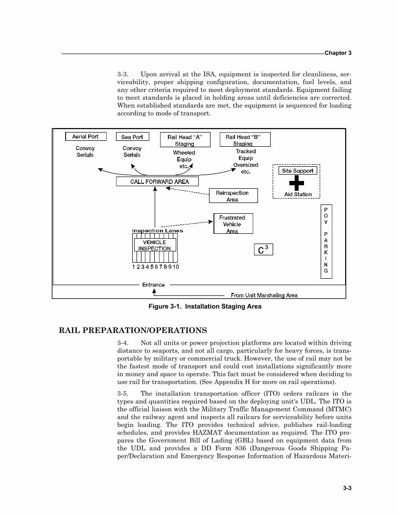
INSTALLATION STAGING AREA 3-1. The installation staging area (ISA) (Figure 3-1) is a centralized loca-tion where deploying units assemble their equipment for continued move-ment to the POE. The installation is normally responsible for the operation and organization of the ISA, but may be augmented by unit teams from de-ployment support brigades (DSBs) or by non-deploying units. The installa-tion normally provides command and control of the ISA by establishing a control center, monitoring unit movements, and validating unit equipment preparation. This chapter discusses DSBs in more depth later.
3-2. The DSBs are United States Army Reserve (USAR) units that pro-vide direct support to installations for unit deployments. Their primary mis-sion is to assist the installation UMO to ensure unit equipment is properly prepared and correctly documented prior to departing the installation, and that the equipment arrives at the port in accordance with call forward move-ment schedules. They also provide hands-on training and guidance to units in equipment preparation and tie-down procedures. DSBs may provide assis-tance in the unit marshaling area (MA) and the installation staging area.
_________________________________________________________________________________Chapter 3
3-3
3-3. Upon arrival at the ISA, equipment is inspected for cleanliness, ser-viceability, proper shipping configuration, documentation, fuel levels, and any other criteria required to meet deployment standards. Equipment failing to meet standards is placed in holding areas until deficiencies are corrected. When established standards are met, the equipment is sequenced for loading according to mode of transport.
Figure 3-1. Installation Staging Area
RAIL PREPARATION/OPERATIONS 3-4. Not all units or power projection platforms are located within driving distance to seaports, and not all cargo, particularly for heavy forces, is trans-portable by military or commercial truck. However, the use of rail may not be the fastest mode of transport and could cost installations significantly more in money and space to operate. This fact must be considered when deciding to use rail for transportation. (See Appendix H for more on rail operations).
3-5. The installation transportation officer (ITO) orders railcars in the types and quantities required based on the deploying unit's UDL. The ITO is the official liaison with the Military Traffic Management Command (MTMC) and the railway agent and inspects all railcars for serviceability before units begin loading. The ITO provides technical advice, publishes rail-loading schedules, and provides HAZMAT documentation as required. The ITO pre-pares the Government Bill of Lading (GBL) based on equipment data from the UDL and provides a DD Form 836 (Dangerous Goods Shipping Pa-per/Declaration and Emergency Response Information of Hazardous Materi-
FM 3-35.4 ________________________________________________________________________________
3-4
als Transported by Government Vehicles/Containers/Vessels), if necessary, for HAZMAT.
3-6. The unit loads the railcars. The following are principles of loading, blocking, and bracing vehicles on flat cars or in boxcars: • Cars must be suitable for safe transportation of the load. • Load and weight limits must not be exceeded. • Loads must not exceed the width and height restrictions over the pro-
posed route. • Loads must be adequately secured on cars.
3-7. The most common and expeditious method of loading vehicles is the circus method. This method uses flatcars as a roadbed with spanners placed between cars. After the loading sequence for the train has been determined, the vehicles are staged in that sequence, called forward to the ramp, and driven onto the flatcars.
SOLDIER READINESS PROCESSING 3-8. Commanders of deploying units must have a formal review process in place to ensure soldiers meet readiness requirements. (TC-AIMS II, when fielded, will have the capability to track some of this information for the commander.) Army regulation (AR) 600-8-101 provides specific readiness pro-cedures and requirements. Unit responsibilities include— • Maintaining and updating personnel rosters. The roster shows shortages
and non-deployable personnel, and is used for readiness reporting and strategic deployment manifesting. Before embarkation at the POE, the roster is updated to identify each element of the unit being moved.
• Identifying and outprocessing non-deployable personnel or those person-nel not military occupational specialty (MOS) qualified. Non-deployable screening is performed in accordance with applicable personnel regula-tions and command directives. ARs 614-30 and 220-1 outline personnel availability criteria.
• Resolving soldier financial problems with the supporting financial insti-tution.
• Resolving soldier legal issues through supporting Office of the Staff Judge Advocate (for example, wills, powers of attorney, insurance, family support and custody issues).
• Ensuring soldier has accurate and current common access card (CAC). • Ensuring deploying personnel prepare a DA Form 3955 (Change of Ad-
dress and Directory Card) for mail forwarding.
3-9. In addition to unit responsibilities, the supporting installation or area command normally establishes SRP checks before and as a part of the deployment process. (See Appendix D, figure D-1, Readiness and Deployment Checklist and figure D-2, instructions for completing the Readiness and De-ployment Checklist.) These checks include personnel records, finance, legal, medical, dental, security, and unit ministry support.
_________________________________________________________________________________Chapter 3
3-5
PERSONAL PROPERTY 3-10. Before deployments, unit procedures must be in place to ensure the security of soldiers’ personal property. This could include the use of a power of attorney by unit personnel to ship and store their property. Soldiers living in barracks should properly pack, label, inventory, and turn in personal property not required or authorized in the overseas area. The unit’s rear de-tachment is responsible for disposition of this property in coordination with the supporting transportation office. Privately owned vehicles (POVs) can be stored in an area designated by the installation or area commander, or left in the custody of a family member or other responsible individual. When time does not permit these POV procedures, the keys of the vehicle and the power of attorney are left with the rear detachment commander or custodian, or a family member.
FAMILY MEMBERS 3-11. Documented procedures for family support while soldiers are gone are essential in deployment planning. Procedures may include forming fam-ily support groups that assist in resolving problems, and formally interacting with Army Community Services, the installation ministry team, the installa-tion Office of the Staff Judge Advocate, and family life center to meet family needs. Single soldiers should be assured that their families will be kept in-formed of their situation. Family support is the responsibility of both the de-ploying commander and the garrison or installation commander. A family as-sistance officer is usually appointed from the staff of the command having control over the moving unit. Responsibilities of this officer may include— • Advising family members of their entitlements for travel and shipment or
storage of household goods. • Advising family members of the need for their sponsors to leave a power
of attorney or letter of authorization, if family members are to arrange for shipment or storage of household goods and POVs.
• Advising family members of the services available through the Red Cross, Army Emergency Relief, and Army Community Services.
• Moving family members if required. • Clearing quarters belonging to family members. • Emphasizing the need for a will. • Establishing a chain of concern for family support group members to ob-
tain support and information.
INDIVIDUAL CLOTHING AND EQUIPMENT INSPECTION 3-12. This inspection is coordinated with the issuance of any equipment pe-culiar to the deployment. All individual equipment, clothing, and unit equip-ment is accounted for according to the unit supply update and through use of DA Form 3645 (Organizational Clothing and Individual Equipment Record)/DA Form 4886 (Issue-in-Kind Personal Clothing Record).
3-13. Unit movement plans include arrangements for transporting troops to an issue facility to fill shortfalls. The soldier's rucksack contains clothing items that are required en route and upon arrival at the unit's destination.
FM 3-35.4 ________________________________________________________________________________
3-6
OVERSEAS ORIENTATION 3-14. Before deployment, unit commanders brief their units on the pro-jected AO. The briefing should include mission and threat; geography (loca-tion, topography, and climate); people (population, race, religion, customs, values, and language); history; economy; infrastructure; natural resources and special environmental considerations; defense forces; political systems; local laws; SOFA; force protection; and hazards of the area.
CLEARANCE FROM THE INSTALLATION 3-15. The unit commander must clear from the installation/home station before deployment. During rapid deployment, the commander may appoint the rear detachment commander to perform administrative and supply func-tions, such as accounting for materiel not accompanying the unit.
3-16. Not all of a unit's table of equipment (TOE) equipment may accom-pany the unit. For example, the unit could be drawing pre-positioned stocks in the AO. The equipment remaining at HS may be turned over to the rear detachment commander or to the installation. Additionally, hand receipts or annexes should be prepared for turn-over of all nonmission essential equip-ment, station property, and installation property authorized by table of dis-tribution and allowances (TDA) or common tables of allowances (CTAs). Units should also— • Turn in excess petroleum, oils and lubricants (POL) and prescribed load
list (PLL) items. • List fixed facilities (motor pools, troop billets, and administration build-
ings, as well as accompanying materiel) to be transferred to a non-deploying unit or turned in to the installation.
• Cancel outstanding requisitions and/or provide a ship-to address to the servicing supply support activity (SSA) in accordance with AR 710-2.
MAINTENANCE 3-17. Maintenance is an essential facet of vehicle preparation for deploy-ment. Consideration must be given to the special requirements associated with hot and cold weather environments.
3-18. For hot climates or deserts, units must have special parts, oils and lubricants. Rust forms faster in high temperatures and tire life is shortened. Oil is consumed more quickly in diesel powered engines. Before deploying to this environment units should consult technical bulletin (TB) 43-0239 and FM 3-97.3 (90-3). For deployments to cold weather climates, unit personnel should consult the appropriate TMs and FM 4-30.32 (9-207).
3-19. The Army Materiel Command will assist units with deployment. As-sistance may be requested through the Logistics Assistance Representatives and the installation Logistics Assistance Office. Types of assistance include application of immediate and urgent modification work orders, packaging, and calibration.
_________________________________________________________________________________Chapter 3
3-7
DEPLOYING DA CIVILIANS AND CONTRACTORS 3-20. The civilian personnel management system ensures that deployed ci-vilians are accounted for and that they receive personnel services. The war-time dimension of civilian personnel management is a subset of the base op-erations support (BASOPS) civilian personnel management function. As such, it is manned entirely in the table of distribution and allowance (TDA) structure. The civilian TDA structure with support from the military person-nel support system provides personnel support to deployed civilians during war and operations other than war (OOTW). Support begins before the de-ployment and lasts until the civilian redeploys. Deployed (or alerted for de-ployment) DA civilian personnel/families are entitled to the same benefits and privileges afforded to soldiers/family members unless precluded by stat-ute. (See FM 1-0 (12-6), for detailed information on deploying civilians.)
3-21. The Army Materiel Command logistics assistance civilian personnel routinely support and/or deploy with their unit. Other DA civilian and con-tractor personnel have habituated relationships and may deploy with their supported units. If the commander decides to deploy DA civilian and contrac-tor personnel, the unit is responsible for planning, training, equipping and transporting these people. Deploying DA civilian and contractor personnel and equipment should be included in TC-AIMS II.
3-22. When U.S. contractors are deployed from their HSs, in support of Army operations/weapon systems, the Army will provide or make available, on a reimbursable basis, force protection and support services commensurate with those provided to DoD civilian personnel to the extent authorized by law. These services may include—but are not limited to—non-routine medi-cal/dental care; mess; quarters; special clothing, equipment, weapons or training mandated by the applicable commander; mail and emergency notifi-cation. Planning must be accomplished to ensure agreed upon support to con-tractors is available to the responsible commander. (See FM 4-100.2 (100-10-2) and FM 3-100.21 (100-21) for detailed information.)
REAR DETACHMENT 3-23. Requirements for rear detachments always exist when units deploy. Nondeployable personnel and equipment (organizational and personal) re-quire positive control. Rear detachments must be trained to perform their critical tasks: • Installation or facility control. • Administrative responsibility of nondeployed personnel. • Storage of POVs and weapons. • Disposition of personal property. • Family assistance in updating soldier status. • Unit property management. • Provision of Class A agent. • Security management.
FM 3-35.4 ________________________________________________________________________________
3-8
SECURITY 3-24. Equipment should be guarded while it is being staged at the installa-tion, or at railheads, or en route to POEs. Units may consider assigning su-percargoes to accompany the equipment. (During transit from the seaport of embarkation (SPOE) to the seaport of debarkation (SPOD)). As a minimum, equipment should be protected against theft and pilferage. Deploying units normally wire ignition keys of deploying vehicles to the steering column. When containers are padlocked, two sets of keys will be available for each locked item (one set for the supercargoes or escorts and one set for the custo-dian). A key custodian is appointed to assist with specialized cargo that may require keys. (See Appendix I for handling classified and sensitive cargo.)
3-25. When handling classified material, the deploying unit performs the following steps before deployment: • Disposes of nonessential files according to AR 380-5, and local SOP. • Consults security or information management directorate for disposition
of classified or cryptographic material. • Prepares classified cargo for shipment. • Assigns escorts or supercargoes for classified cargo.
SECTION II – ORGANIZATION RESPONSIBILITIES
3-26. One of the key principles identified in the Power Projection Func-tional Area Assessment (FAA) was the fact that installations and garrison staffs are the primary enablers for preparing and deploying the force. Spe-cifically they must—
• Modernize infrastructure and maintain a power projection capability. • Provide the necessary trained personnel to prepare and deploy the force. • Plan for rapid augmentation to meet surge requirements. • Mobilize, prepare, and deploy follow-on forces. • Continue routine base operations at required levels, while accomplishing de-
ployment and mobilization operations. • Be prepared to execute mobilization and deployment operations without the
benefit of borrowed military manpower drawn ordinarily from tenant organiza-tions.
FORSCOM Mobilization/Deployment Handbook
EMERGENCY OPERATIONS CENTER 3-27. The multitude and variety of actions required of an installation staff during a force projection operation mandates the need for centralized control. The installation establishes an emergency operation center (EOC) to satisfy this need. These centers provide the commanders with the ability to schedule facilities, husband resources, manage diverse requirements, track deploying forces and, most importantly, manage change. During a force projection op-
_________________________________________________________________________________Chapter 3
3-9
eration, the time value of deployment facilities is at its peak. Any time these facilities are not operating at maximum efficiency is lost time and slows the deployment process.
INSTALLATION TRANSPORTATION OFFICER 3-28. The Installation Transportation Officer (ITO) is a pivotal participant in the force projection process providing links for the deploying units to USTRANSCOM services, to commercial sources, and to power projection platform operational expertise. The ITO also provides the unit movement of-ficer a link to all commercial transportation.
3-29. The ITO obtains routings from MTMC for all shipments associated with moving military units by ordering rail cars for equipment for all rail movements and appropriate trucks and vehicles for other shipments. For rail movements, the unit prepares, updates, and distributes the rail-loading plan in time to obtain carrier equipment and meet deployment load-out schedules. The ITO reviews the unit’s rail load plan for accuracy. The ITO orders truck service from the motor carrier after notification of routing from MTMC. The ITO coordinates with the rail inspector for the pre-loading inspection of all rail cars; provides materiel-handling equipment (MHE) for loading; and coor-dinates and monitors loading to verify that equipment is loaded in accor-dance with the loading plan.
3-30. The ITO generates a request for aircraft in accordance with DoD Regulation 4500.9-R and AR 59-9, if the need for an aircraft is identified for a unit move. The ITO coordinates with the unit being moved to provide MHE availability, loading equipment times, the specifications of equipment to be loaded, the number of troops to be carried, any hazardous cargo that will be transported, the mission, and priorities.
3-31. The unit prepares the convoy request and then submits the request through the installation to the respective state Defense Movement Coordina-tor (DMC) for action in accordance with FM 4-01.40 (55-30). To assist in cen-tralized convoy management, the computerized mobilization movement con-trol (MOBCON) system/program is utilized. The MOBCON program gives the state DMCs an automated system that plans, schedules, and deconflicts convoys within CONUS (MOBCOM will be discussed further in Chapter 4). The ITO schedules convoys locally if the MOBCON is unable to process the request. The ITO coordinates with the moving unit as required and notifies authorities of areas through which convoys will transit.
DEPLOYMENT SUPPORT BRIGADES 3-32. The Deployment Support Brigades (DSBs) are USAR units that pro-vide direct support to installations for unit deployments. They are under the operational control of MTMC. In their direct support role, the DSB's primary mission is to assist the installation in ensuring unit equipment is properly prepared and correctly documented prior to departing the installation, and that the equipment arrives at the port in accordance with call forward move-ment schedules. Based on requirements identified by the installation and deploying unit in coordination with the port, the DSB can assist in— • Preparing movement documentation.

FM 3-35.4 ________________________________________________________________________________
3-10
• Providing rail or air load planning assistance. • Advising on proper application of logistics applications of automated
marking and reading systems (LOGMARS) placards. • Establishing transportation inspection points. • Providing guidance on shipment of HAZMAT cargo. • Assisting with the preparation and correction of OELs. • Providing hands-on training/guidance in equipment preparation and tie-
down procedures. • Providing liaison between the port command and the ITO and UMOs.
3-33. Each DSB includes a command group and unit movement teams (UMTs), consisting of six individuals per team. UMTs have been predesig-nated and assigned to specific installations. Those installations without des-ignated UMTs can request DSB assistance in peacetime and during mobiliza-tion. Requests for DSB assistance are made to MTMC. MTMC responds to requests for assistance by— • Scheduling a DSB to perform annual training (AT) with the unit and/or
ITO. • Tasking the DSB through the United States Army Reserve Command
(USARC) to provide assistance during active duty training. • Coordinating with FORSCOM to resolve any support issues.
CONUS REPLACEMENT CENTER 3-34. CONUS Replacement Centers (CRCs) are located at several sites in the United States. They prepare non-unit related personnel (NRP) for de-ployment and receive individuals upon redeployment. NRPs consist of five categories: Active Component (AC) personnel, Individual Ready Reserve (IRR) (already accessed onto active duty), Department of Defense civilians, contract civilians, and Red Cross civilians. CRCs are only activated when there is a Presidential Selective Reserve Call-Up (PSRC) and are operational 24 hours a day, seven days a week. More information on CRCs is in FM 1-0 (12-6).
DEPLOYMENT PROCESSING CENTER 3-35. A deployment processing center (DPC) is one term used for a no-tional group of activities that do not exist in a single physical form. The term is used to encompass all installation activities assisting in the deployment process. Since DPC activities are unique to each installation, based on mis-sion and facilities, they may be referred to by different terms.
3-36. Some installations, such as Fort Drum, have world class deployment facilities. In such instances, deployment activities, such as medical screening, records updating, and mission briefing take place in a central location. In other instances, such as at Fort Polk where there is no central deployment facility, these activities spread out over a 50-mile radius.
3-37. To assist in the deployment of its soldiers, the United States Army Europe (USAREUR) established a DPC at Rhine-Main Ordnance Barracks. The mission of this DPC is to control, stage, and conduct final processing of
_________________________________________________________________________________Chapter 3
3-11
units (soldiers and their equipment) for deployment by air from the aerial port of embarkation (APOE) at Ramstein Air Base. The DPC may provide a staging area for equipment (including helicopters), air pallet building facili-ties, maintenance support, fueling and defueling capability, ammunition sup-port, and communication and automation support to the deploying unit. The DPC also provides life support for deploying and redeploying units transiting at the APOE.
3-38. The processing concludes with the Air Force joint inspection at the airfield. Upon successful completion, the equipment is moved in chalk forma-tion to the ready line. The DPC may also operate the personnel holding area at the airfield.
SECTION III – FORCE PROTECTION/ANTITERRORISM
"...terrorists should know that we will not simply play passive defense. America will de-fend itself and its interests through active measures..."
Former Secretary of Defense, William Cohen
3-39. A series of incidents in recent years has created an increased empha-sis on force protection (FP) throughout the DoD. FP consists of those actions that prevent or mitigate hostile actions against DoD personnel (to include family members), resources, facilities, and critical information. FP involves coordinating and synchronizing offensive and defensive measures to enable the joint force to perform while degrading opportunities for the enemy. FP in-cludes air, space, and missile defense; chemical, biological, radiological, nu-clear, and explosives (CBRNE) activities; antiterrorism; defensive informa-tion operations; and security to operational forces and means. FP does not in-clude actions to defeat the enemy or protect against accidents, weather, and disease. FP at all levels minimizes losses to hostile action. Skillful and ag-gressive counterintelligence and threat assessments decrease the vulnerabil-ity of friendly forces. Effective operations security (OPSEC) keeps adversar-ies from exploiting friendly information. Proper dispersion of CSS assets helps reduce losses from enemy fires and terrorist action. CSS commanders must use camouflage discipline, local security, and field fortifications, which reduce losses due to enemy actions. Protection of electronic links and nodes, to include combat troops with electronic devices, is vital to protection of in-formation, information systems, and soldiers. There is no more important re-sponsibility than force protection.
3-40. Force protection is an inherent command responsibility and must be fully integrated into every unit’s mission. A commander must continually re-view his unit’s FP posture and crosswalk it with current and changing policy and threat levels. The threat of enemy interdiction during deployment opera-tions, particularly for forward presence forces, presents a special challenge. The challenge is to protect geographically dispersed deploying forces (which have limited self-protection capability while configured for deployment) and materiel transiting the various links and nodes of the deployment process. FP demands the personal involvement of commanders to ensure the best pos-
FM 3-35.4 ________________________________________________________________________________
3-12
sible security consistent with the threat to personnel and mission-essential resources.
3-41. To meet the terrorist threat, an integrated and comprehensive anti-terrorism program must be developed and implemented at every echelon of command. The program is designed to foster a protective posture in peace-time (units performing normal duties and serving in security assistance or-ganizations, peacekeeping missions, or mobile training teams) that will carry over to a wartime environment. Antiterrorist measures are intended to iden-tify and reduce the risk of loss or damage of potential targets and to develop procedures to detect and deter planned terrorist actions before they take place, thereby reducing the probability of a terrorist event. The measures also encompass the reactive or tactical stage of an incident, including direct contact with terrorists to end the incident with minimum loss of life and property. See JP 3-07.2 for more on antiterrorism.
3-42. All units must ensure force protection/antiterrorist plans are inte-grated into movements through high threat areas such as, ports, MSRs, and depots. Commanders must include the following areas in force protection pre-deployment planning: • Threat and vulnerability assessments. Units assess the threat and their
own vulnerability before deployment. • Security planning. Units must take the results of threat and vulnerabil-
ity assessments and develop security plans for self-protection while in-transit. Although emphasis must be on movements through high threat areas, commanders should not discount appropriate security measures for movements in lower threat areas. Security plans for movements through high threat areas must be completed and approved by the next higher command (at the minimum, the battalion (BN) commander). Ad-vanced or on-board security augmentation should be considered for travel through high threat areas. Commanders/senior Army representatives ac-companying the movement are responsible to ensure security measures sufficiently address vulnerabilities. Movements may require tailored in-telligence/counterintelligence support, host nation assistance, or pre-planned alternate routes based on the vulnerabilities associated with the movement.
• Training. Units moving through high threat areas ensure personnel re-ceive pre-deployment training on rules of engagement, AOR threat orien-tation, defensive tactics, techniques and procedures (TTPs)/exercises, and security equipment. Training is performance oriented and provides sol-diers and leaders the training required to defend against a terrorist threat and/or mitigate the effects of an attack.
• Movement tracking. Major Army Commands (MACOMs) will establish a process to track movements through high threat areas for units with 30 or more personnel. MACOMs are required to report specific movements to HQDA (ODCSOPS).
• Logistics. Predictability and support of unit movements are a unit’s greatest vulnerability. Unit commanders must understand that predict-ability places a higher demand on the unit’s ability to know the local threat, assess unit vulnerabilities, and develop self-protection measures.
_________________________________________________________________________________Chapter 3
3-13
3-43. The potential abilities of adversaries to orchestrate asymmetric threats against U.S. forces require that every measure be taken to protect those forces during the deployment process. The advent of the Cable News Network (CNN) and instant worldwide news, coupled with the difficulty of hiding port operations, makes the threat real. Installations have important responsibilities in preparing for possible asymmetric threats. Comprehensive FP requires the employment of a full array of active and passive measures and the integration and coordination of intelligence and security programs, risk management techniques and safety programs to increase individual awareness of potential threats. Agreements with civil authorities, clear lines of authority, training, and security procedures all influence our ability to op-erate in an asymmetric threat environment and to combat terrorism. See FM 4-0, FM 3-07.2 (100-35), (to be developed), FM 3-19.4, (to be developed), and JP 3-35 for more information on force protection and physical security.

4-1
Chapter 4
Movement to and Activities at Ports of Embarkation
The first surge began with the need to put combat power on the ground in Saudi Arabia as quickly as possible. The decision to deploy the 82d Defense Ready Bri-gade (DRB1) meant that the United States (U.S.) Transportation Command (USTRANSCOM) had to provide the 82d with 250 C-141 equivalents, though USTRANSCOM could only guarantee 90. Within hours, C-141 and C5A aircraft from U.S. bases all over the world were landing at Pope Air Force Base. Because the Air Force was unable to predict ei-ther type of aircraft arriving or the times of arrival, 1st Corps Support Command (COSCOM) Transportation Corps soldiers were constantly reconfiguring loads based on the type of aircraft and needs to fit tactical exigencies in Saudi Arabia, making for an extremely demanding mission. As aircraft landed, little time was wasted. Aircraft loads were often reconfigured and loaded within minutes of the aircraft touching down.
Spearhead of Logistics A History of the U.S. Army Transportation Corps
Contents
Section I – Principles of Movement 4-2 Principles 4-2 Liaison Officer 4-2 Section II – Fort-To-Port Movement 4-3 Convoy Operations 4-3 Rail Operations 4-4 Section III – Activities at the Ports of Embarkation 4-4 Seaports 4-4 Military Traffic Management Command (MTMC) 4-4 MTMC Deployment Support Team (DST) 4-5 Transportation Terminal Brigade (TTB) 4-5 Military Sealift Command (MSC) 4-6 U.S. Coast Guard (USCG) 4-6 Port Support Activity (PSA) 4-7 Supercargo 4-7 Port Operations Center 4-8
Support Installations (SI) 4-8 Deploying Unit 4-8 Marshaling Areas 4-9 Staging Areas 4-10 Airports 4-11 Departure Airfield Control Group (DACG) 4-11 Tanker Airlift Control Element (TALCE) 4-11 Marshaling Area 4-12 The Alert Holding Area 4-12 The Call Forward Area 4-13 The Ready Line and Loading Ramp Area 4-14 Railhead 4-15 Sequence Loads For Rail Spurs 4-15 Move To Rail Staging Areas 4-15 Finalize Rail Load 4-16 Move To Railhead and Loading the Trains 4-16
FM 3-35.4 ________________________________________________________________________________
4-2
Units normally deploy via airports and seaports of embarkation. Each power projection platform has an associated strategic seaport and airport. The proximity of the port facilities to the platform determines the type of movement to the port required. At some ports, the distance is short, so units can convoy; at others, commercial support is required.
In the overall global deployment scheme, each point at which a unit changes the type of transportation platform (that is, air, ship, rail, com-mercial and military truck) is a node. Nodes are, by their nature, friction points. Friction slows the deployment time line. Therefore, throughput, the amount of cargo that can move through a node, becomes a principal concern. This is particularly true at the POEs. The objective is to maxi-mize quickly the throughput capability by moving transportation assets, units, and enablers into position for immediate execution of the plan. Any time lost in this pursuit is lost forever and, if ports are used at less than capacity, the unused portion is irrecoverable.
SECTION I – PRINCIPLES OF MOVEMENT
PRINCIPLES 4-1. Principles discussed earlier are applicable to fort-to-port movement in general and specifically to APOE and SPOE operations. • Precision in all movements, units and support elements, being neither
late nor early to the ports, reduces lost capacity, and the payoff is a re-duction in the time required for force closure.
• The synchronization of fort-to-port deployment activities limits waste of critical resources. All organizations involved must work together to affect a smooth and timely deployment.
• Knowledge creates an environment where sound and timely decisions can be made. A complete understanding of the processes, including the auto-mated information systems (AIS) used, is paramount for a smooth de-ployment.
• The speed achieved in each phase and through each node affects the ve-locity of the entire force projection process. To get to the fight as quickly as possible, speed is essential in the loading and unloading of unit cargo.
LIAISON OFFICER 4-2. A liaison officer from the deploying unit to each POE is critical to the unit’s smooth transit at the port and the achievement of precision, synchroni-zation, knowledge and speed. Liaison is defined as contact or communication maintained between elements of military forces or other agencies to ensure mutual understanding and unity of purpose. It is an effective way for deploying units, particularly separate brigade and higher level organizations, to ensure the commander’s intent is understood and properly influences the deployment process. It can also reinforce safety, resolve problems, limit the time required
_________________________________________________________________________________Chapter 4
4-3
for decisions, and keep the commander informed. A liaison team can directly improve the synchronization between an installation and port activities.
The practice of using liaison officers as "directed telescopes" to facilitate com-mand and control is almost as old as war itself. Beginning in antiquity and con-tinuing into the modern era, ground commanders have relied on carefully selected subordinates to serve as their eyes and ears. These trusted agents, often with di-rect access to the deliberations that produced the "commander's intent," have pro-vided invaluable information to the commander's immediate staff and others. And during the heat of battle they assisted commanders by communicating orders and controlling units.
Major General Robert H. Scales, Jr., U.S.A Commandant, U.S. Army War College
PARAMETERS, U.S. Army War College Quarterly - Winter 1998.
SECTION II – FORT-TO-PORT MOVEMENT
CONVOY OPERATIONS 4-3. Most units conduct convoy operations to get to the ports of embarka-tion. A convoy is a group of vehicles organized for the purpose of control and orderly movement under the control of a single commander. Theater policy (OCONUS unit), standardization agreement, or the HN directs the minimum number of vehicles in a convoy. In the absence of policies to the contrary, con-voys consist of six or more vehicles. Vehicles in a convoy are organized into groups to facilitate command and control, and normally move at the same rate.
4-4. To assist in centralized convoy management, FORSCOM has devel-oped and implemented a computerized mobilization movement control sys-tem/program known as MOBCON. The MOBCON software uses the national highway transportation network (NHTN) in conjunction with a system of nodes (road junctions, critical points) and links (road segments between nodes). About 380,000 miles of roadway with 28,500 nodes and 45,000 links represent this network. MOBCON software uses the electronic NHTN database to schedule and deconflict convoys within CONUS. The deconflic-tion process permits only one convoy to operate over a segment of road at any given time. Normally, accomplishment of this process occurs by changing times of movement or rest halt duration. MOBCON usually separates con-voys by a 10-minute time gap. MOBCON provides visibility of all military traffic processed in the system. It links all DMCs and provides a means of communication. A convoy processed in one state and passing through other states has immediate visibility of all MOBCON users.
4-5. FM 4-01.40, (55-30), DoD 4500.9, and AR 55-80 contain additional in-formation concerning convoy operations and MOBCON . See Appendix J for a convoy commander’s checklist and a convoy briefing outline.
FM 3-35.4 ________________________________________________________________________________
4-4
RAIL OPERATIONS 4-6. Although most units conduct convoy operations to get to the POE, not all units or power projection platforms are located within driving distance to seaports, and not all cargo, particularly for heavy forces, is transportable by military or commercial truck. In these cases, rail travel is used. The railroad facilities serving the POE may be at the head of a pier or at an inland trans-fer point. The transfer point may be truck-to-rail or amphibian-to-rail. Ter-minal service units will load or unload rail equipment during cargo-handling operations. These units must plan rail-loading procedures and secure cargo on rail cars. They must also know the type of equipment required at destina-tion to load and unload cargo to minimize the amount of rail equipment used and to make the loading/unloading as simple and quick as possible. See FMs 4-01.41 (55-20 and 55-21), FM 4-01.50 (55-17), and Appendix H for more in-formation on rail operations.
SECTION III – ACTIVITIES AT THE PORTS OF EMBARKATION
SEAPORTS 4-7. There are essential activities involved in port operations that involve DoD and Army units and ad hoc organizations. The following is a description of these key organizations and of the areas in which they operate at seaports.
MILITARY TRAFFIC MANAGEMENT COMMAND 4-8. The Military Traffic Management Command (MTMC) is the surface transportation component of DoD’s USTRANSCOM and is DoD’s single port manager. In peacetime, MTMC serves as the link between DoD shippers and commercial carriers, such as, those in the trucking and rail industries. It en-sures efficient, safe transportation service to customers. MTMC has a per-manent presence in 24 ports worldwide. In each port, MTMC stages cargo, plans and directs loading, and documents cargo movement. (For further de-scription and guidance of activities and functions, visit the MTMC web-site at www.mtmc.army.mil.)
4-9. Deploying units receive their port call instructions from MTMC. The port call message identifies the date the unit must arrive at the SPOE for movement processing. MTMC schedules units to arrive at the POE in suffi-cient time to allow processing and loading to meet vessel sailing schedules. Units, in coordination with the ITO, backward plan for the movement to the SPOE and coordinate movement schedules with MTMC. Deployment duties and responsibilities of MTMC include— • Select unit SPOE/SPOD with the ASCC. • Determine movement requirements and coordinate vessel selection with
Military Sealift Command (MSC). • Prepare and issue port call messages. • Receive PSAs from supporting installations and direct their functions
and activities. • Receive, stage, and transship unit equipment in the port.
_________________________________________________________________________________Chapter 4
4-5
• Establish and direct port communications, safety policies, and physical security procedures.
• Regulate military traffic within the port. • Direct DSBs to assist deploying units. • Assist ITOs and traffic managers in shipping unit equipment and sup-
plies to the POE. • Develop stow plans, supervise vessel loading, inspect vessel readiness,
and provide documentation.
MTMC DEPLOYMENT SUPPORT TEAM 4-10. The MTMC deployment support team (DST) is a team of personnel, both military and/or Department of the Army civilian (DAC), who are di-rected to open and temporarily operate an SPOE until the transportation terminal brigade (TTB) is operational. When alerted, a DST is formed and immediately deploys to the SPOE to coordinate contracts, set up operations, and begin to receive cargo. The team also plans for traffic flow, obtains waiv-ers and clearances, establishes liaison with the deploying unit, develops pre-stow plans, and provides reports to MTMC’s Deployment Support Command (DSC), Command Operation Center (COC) or to headquarters, MTMC Com-mand Operations Center.
TRANSPORTATION TERMINAL BRIGADE 4-11. TTBs are USAR units that allow MTMC to expand the number and capability of seaports. They normally take over responsibility for port opera-tions from the DST. TTBs conduct ocean terminal operations at established ports where existing manpower, equipment, and infrastructure are available. When operating in CONUS, TTBs are assigned to MTMC. They may be de-ployed OCONUS to expand the number and capability of ports for sustain-ment or redeployment purposes.
4-12. TTBs consist of soldiers and systems. They depend on the infrastruc-ture of the port facility, contract stevedores, and host nation support (HNS) at the terminals where they are assigned to operate. A typical TTB operates two or three berths simultaneously (four or five berths for limited surge peri-ods), provides traffic management, and supervises contracts. It employs Army standard management information systems such as Integrated Com-puterized Deployment System (ICODES), Worldwide Port System (WPS), and Integrated Booking System (IBS), as well as AIT. Its major responsibili-ties are— • Establish and maintain liaison with port authorities. • Establish and maintain liaison with the PSA, the supporting installation
or the area support group (ASG), and the marshaling area commander. • Receive, supervise load/discharge of, and transship cargo according to
supported command directives. • Establish and maintain liaison with the local MSC representative. • Prepare and update port terminal operations plans. • Analyze terminal workload capabilities and quantify missions that may
be performed by contract, HN, or military stevedore support.
FM 3-35.4 ________________________________________________________________________________
4-6
• Delegate unit assets (whether assigned, attached, or contracted) to ac-complish terminal missions.
• Analyze, plan, and control terminal cargo movements through the termi-nal.
• Prepare and update vessel stow plans. • Plan vessel work loads. • Execute port security plans in coordination with the U.S. Coast Guard
(USCG). • Execute commercial contracts to hire stevedores. The civilian stevedore
company provides vessel/terminal work. It normally will hire gangs to do the actual loading and lashing.
• Compile cargo receipt and processing data in automated systems for documentation, management information, and in-transit visibility (ITV).
• Perform liaison with deploying units. • Coordinate all cargo activity and stow plans with the vessel master or his
representative.
MILITARY SEALIFT COMMAND 4-13. MSC is the sea transportation component of DoD’s USTRANSCOM. The mission of the MSC is to provide ocean transportation of equipment, fuel, supplies and ammunition to sustain U.S. forces worldwide during peacetime and in war for as long as operational requirements dictate.
Note. Visit the MSC web site at www.msc.navy.mil for further description and guidance of activities and functions.
COAST GUARD 4-14. The Coast Guard’s tasks in the maritime aspects of major theater warfare encompass critical elements of naval operations in littoral regions, including port security and safety, military environmental response, mari-time interception, coastal sea control and force protection. This includes har-bors, channels, approaches, and vessels that are in these areas. The USCG physical security plan is integrated with the port commander's physical secu-rity plan for developing and maintaining comprehensive physical security and antiterrorist plans. The USCG’s operational capabilities figure impor-tantly in small-scale contingencies and port security in overseas theaters, as well as in other important MOOTW missions. The role of the USCG in de-ployment security takes on a greater importance, as adversaries of the United States are more likely to engage in asymmetric warfare. In addition to waterside physical security, the USCG's other duties include— • Regulating the shipping, handling, and pierside storage of hazardous
cargo, and interfacing with military authorities, as the senior DoD port safety agent.
• Issuing hazardous cargo permits. • Supervising vessel fire prevention programs.
_________________________________________________________________________________Chapter 4
4-7
Note. (Visit the USCG web site at www.uscg.mil for further description and guidance of activities and functions).
PORT SUPPORT ACTIVITY 4-15. The PSA is an ad hoc organization comprised of military and civilian personnel with specific skills that aid the port commander in receiving, proc-essing, and clearing cargo at the SPOE. CONUS installations are delegated specific ports to which they must provide support. This includes providing the PSA and associated logistic support for deploying units. A general nu-meric sizing rule of thumb for the PSA task force is a company for a deploy-ing brigade, a battalion for a deploying division, and a brigade for a deploying corps. This relates to size only, not organizational structure.
4-16. Commanders responsible for deployments should not (where practi-cal) allocate deploying units to operate the PSA organization. PSA organiza-tions should maintain the same core personnel for the duration of the de-ployment and augment the TTB, as required, with unique deploying unit skills such as aviation personnel and munitions experts. Terminal operations success depends on a well-organized PSA augmenting and supplementing the port commander's SPOE mission.
4-17. The PSA establishes the necessary communications to ensure the proper flow of cargo. It provides daily operational reports of cargo received, of maintenance performed, and of operational problems, to the port commander.
4-18. The commander providing PSA support first considers the type of unit and equipment being deployed. He then selects personnel qualified to handle the physical security of classified equipment and protected cargo, per-sonnel with unique equipment operator skills, and maintenance personnel to correct primary weapon system and deploying equipment deficiencies. PSA duties include— • Receiving, inspecting, and documenting deploying cargo. • Correcting cargo deficiencies that preclude sea movement. • Operating unique equipment (normally neither contract nor military ste-
vedores can operate track vehicles and other atypical military cargo). • Providing backup organizational and limited DS maintenance for deploy-
ing units. • Providing a physical security guard force for classified and protected
cargo. • Providing blocking/bracing personnel and tools to secure secondary loads. • Providing workers with safety equipment, such as vests, lights, gloves,
and goggles. • Moving deploying unit equipment according to the port traffic plan. • Providing messing/billeting and medical support to transiting units. • Providing miscellaneous administrative support.
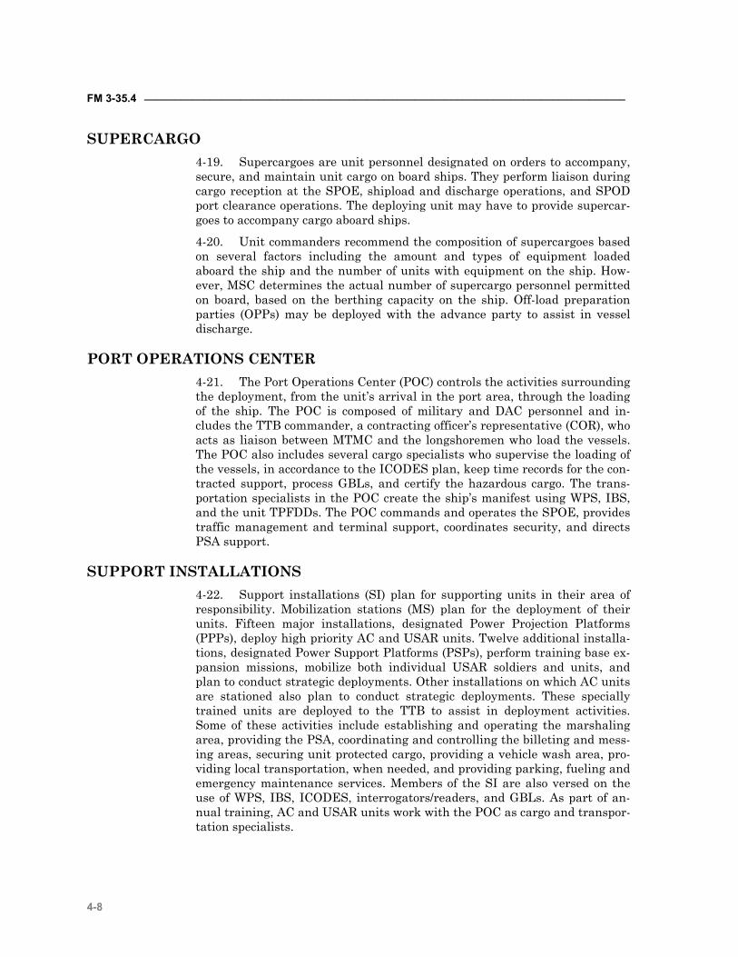
FM 3-35.4 ________________________________________________________________________________
4-8
SUPERCARGO 4-19. Supercargoes are unit personnel designated on orders to accompany, secure, and maintain unit cargo on board ships. They perform liaison during cargo reception at the SPOE, shipload and discharge operations, and SPOD port clearance operations. The deploying unit may have to provide supercar-goes to accompany cargo aboard ships.
4-20. Unit commanders recommend the composition of supercargoes based on several factors including the amount and types of equipment loaded aboard the ship and the number of units with equipment on the ship. How-ever, MSC determines the actual number of supercargo personnel permitted on board, based on the berthing capacity on the ship. Off-load preparation parties (OPPs) may be deployed with the advance party to assist in vessel discharge.
PORT OPERATIONS CENTER 4-21. The Port Operations Center (POC) controls the activities surrounding the deployment, from the unit’s arrival in the port area, through the loading of the ship. The POC is composed of military and DAC personnel and in-cludes the TTB commander, a contracting officer’s representative (COR), who acts as liaison between MTMC and the longshoremen who load the vessels. The POC also includes several cargo specialists who supervise the loading of the vessels, in accordance to the ICODES plan, keep time records for the con-tracted support, process GBLs, and certify the hazardous cargo. The trans-portation specialists in the POC create the ship’s manifest using WPS, IBS, and the unit TPFDDs. The POC commands and operates the SPOE, provides traffic management and terminal support, coordinates security, and directs PSA support.
SUPPORT INSTALLATIONS 4-22. Support installations (SI) plan for supporting units in their area of responsibility. Mobilization stations (MS) plan for the deployment of their units. Fifteen major installations, designated Power Projection Platforms (PPPs), deploy high priority AC and USAR units. Twelve additional installa-tions, designated Power Support Platforms (PSPs), perform training base ex-pansion missions, mobilize both individual USAR soldiers and units, and plan to conduct strategic deployments. Other installations on which AC units are stationed also plan to conduct strategic deployments. These specially trained units are deployed to the TTB to assist in deployment activities. Some of these activities include establishing and operating the marshaling area, providing the PSA, coordinating and controlling the billeting and mess-ing areas, securing unit protected cargo, providing a vehicle wash area, pro-viding local transportation, when needed, and providing parking, fueling and emergency maintenance services. Members of the SI are also versed on the use of WPS, IBS, ICODES, interrogators/readers, and GBLs. As part of an-nual training, AC and USAR units work with the POC as cargo and transpor-tation specialists.
_________________________________________________________________________________Chapter 4
4-9
DEPLOYING UNIT 4-23. At the SPOE, the deploying unit also has responsibilities. These re-sponsibilities include establishing a relationship with the unit that controls the marshaling area, identifying personnel and equipment to be moved, iden-tifying cargo requiring special and hazardous handling, and providing trained load teams. (A more detailed listing of deploying unit responsibilities appears later in this chapter). (See figure 4-1, Notional SPOE, for a sug-gested layout of the SPOE and the activities/organizations necessary for de-ployment.)
Figure 4-1. Notional Sea Port of Embarkation.
MARSHALING AREAS 4-24. Support installations establish a final en route marshaling area, if space permits, where unit equipment is configured for overseas movement before entering the port staging area. This marshaling area is designated by, and under the control of, the support installation and serves to facilitate the call forward of equipment.
4-25. There is no set organization or physical layout for a marshaling area. It is organized to meet operational requirements within available space by grouping related functions. Cargo may be subdivided into any number of
FM 3-35.4 ________________________________________________________________________________
4-10
categories, but usually does not include the containers. The categories and the volume of cargo in each category play a significant role in the marshaling area. The most widely used categories are containerized, roll-on/roll-off (RO/RO), and special (oversize, heavy lift, hazardous, and security) cargo.
4-26. Regardless of the type of cargo, marshaling areas should provide for the following activities and elements: • Act as a central control and inspection point with multiple lanes for cargo
entering or exiting the marshaling yard. Containers are usually segre-gated into a separate location in the marshaling yard.
• Act as auxiliary internal checkpoints (CPs) for containers and cargo en-tering the yard from a beach, or a rail spur, or by helicopter to a landing zone within the yard.
• Act as the segregator of inbound containers and cargo, separating by size and type and, within these groupings, by priority, destination, and spe-cial handling (security, mail, hazardous, and so forth).
• Provide a traffic circulation plan showing movement flow into, through, and out of the marshaling area.
• Repair minor damage to containers. • Provide equipment parking. • Facilitate unit maintenance of equipment. • Facilitate messing and comfort facilities. • Provide a spill contingency plan including emergency supplies and
equipment for isolating and disposing of HAZMAT spills. • Provide emergency response plan for fire or other emergencies.
4-27. In addition to the space for temporary storage of containers, there should be space for any required container repackaging, container repair, or other operational or administrative functions. Space requirements are influ-enced by type, size, and number of containers handled, length of time con-tainers are held in the marshaling area, and container handling equipment (CHE) available.
4-28. The marshaling area is located as near the vessel, rail, air, or truck discharge or load site as practicable. Enemy capabilities and activities may require dispersion of activities or affect selection of marshaling yard location.
STAGING AREAS 4-29. Staging at the SPOE is used for assembling, holding and organizing personnel, equipment, and sustaining material in preparation for onward movement from the port. Staging allows the port manager to maximize port throughput capability by strategically placing personnel, equipment and sus-taining material in such a way as to make loading quick and efficient. The staging area is the general locality established for the concentration of these units, unit personnel, and sustaining materials.
4-30. With the move toward the IBCT/objective force and the invent of the large medium speed roll/on-roll/off ships (LMSRs), time spent in staging is critical. The LMSR has been built to accomplish the loading and unloading of equipment in a total of ninety-six (96) hours combined. Operational tests on
_________________________________________________________________________________Chapter 4
4-11
the LMSRs show that the majority of the ninety-six hours is taken up in the loading process. Thus, the function of staging profoundly affects the time re-quired to move the force forward.
OBSERVATION: Ship loading operations are prolonged when staging areas are disorganized. DISCUSSION: The vehicles of one unit were parked in no particular scheme or sequence. This hampered loading operations of the port. The unit marshaling areas are used to receive convoys and process vehicles before they are staged for loading. Preventative maintenance checks and services (PMCS) are performed as well as any required organizational or direct support maintenance; nested loads (secondary loads on prime movers) are checked for security and documentation. LESSON: A representative from the major unit (brigade or regiment) should be at the port from the beginning of the load out and be authorized to make decisions regarding priorities. Park vehicles by type of vehicle first, then further divide them by subordinate unit. The major unit indicates its priority for loading by the order in which the vehicles are parked. This is beneficial to both the deploying units in po-sitioning vehicles and the terminal transportation unit (TTU) in calling vehicles for-ward for loading.
Call 90-11 Special edition, Getting to the Desert
AIRPORTS 4-31. The Aerial Port of Embarkation (APOE) is the interface between land transportation and strategic airlift. Departure airfield operations occur in four separate areas and involve activities of the unit, (which have already been discussed), the A/DACG, and the tanker airlift control element (TALCE). These areas are the marshaling area (MA), the alert holding area, the call forward area (CFA), and the ready line and loading ramp area. (See figure 4-2, Notional Aerial Port of Embarkation, for details.) Some of the du-ties within these areas mirror those that occur in the SPOE. Appendix K con-tains equipment preparation and joint inspections procedures. See FM 55-9, for further guidance. Responsibilities are discussed below.
FM 3-35.4 ________________________________________________________________________________
4-12
Figure 4-2. Notional Aerial Port of Embarkation
DEPARTURE AIRFIELD CONTROL GROUP 4-32. The departure airfield control group (DACG) is normally an ad hoc organization provided by the supporting installation. The TALCE coordinates the overall airlift operations at the departure airfield (see DoD 4500.9-R, Part III). (See Appendix L for deploying unit, DACG planning and prepara-tion phase requirements.) Its size and capabilities are mission dependent. The DACG is task organized with personnel and equipment not associated with the deploying units. Cargo transfer companies are best suited to per-form this mission.
TANKER AIRLIFT CONTROL ELEMENT 4-33. The TALCE is a provisional, deployed Air Mobility Command (AMC) organization established at fixed, en route, and deployed locations where AMC operational support is non-existent or insufficient. The TALCE provides continuing on-site management of AMC airfield operations including com-mand and control, communications, aerial port services, maintenance, secu-rity, weather, and intelligence—those critical elements needed to ensure safe and highly efficient air base activities for all tanker and airlift operations. A TALCE is composed of mission support elements from various units and de-ploys in support of special assignment airlift missions (SAAMs), joint air-
_________________________________________________________________________________Chapter 4
4-13
borne/air transportability training (JA/ATT), tanker support, and contin-gency/emergency relief operations on both planned and "no-notice" bases.
MARSHALING AREA 4-34. The marshaling area is located at the airfield or in the vicinity of the airfield. Marshaling area activities are the responsibility of the deploying unit and the deploying commander. The marshaling area activities should take place as close as possible to the departure airfield. Its location should not cause unnecessary congestion to airfield operations or undue hardship to the deploying unit.
Support Installation and Unit Responsibilities
4-35. The support installation (SI)/base commander who provides and con-trols the marshaling area assists the deploying forces. The commander pro-vides necessary support functions that allow the deploying unit to concen-trate on deployment preparations. These support functions include providing emergency maintenance, providing POL-including defueling capability, and related services.
4-36. The marshaling area is where units may start, continue, or complete preparation for strategic loading. These preparations include assembling ve-hicles, equipment, supplies, and personnel into mission loads (chalks). These loads are manifested and sent to the alert holding area upon notification from the DACG or deploying units. The units also prepare personnel and cargo manifests for deployment, prepare additional required paperwork, (such as, hazardous or agricultural certification), brief personnel on the situation and mission, movement plan, assembly plan, operational plan, con-voy discipline, loading procedures, safety, and assembly procedures once at the POD. The unit ensures that adequate shoring and dunnage material for aircraft loading is readily available, provides personal safety equipment to load team members, and appoints and briefs planeload or troop commanders for departure from the POE.
DACG Responsibilities
4-37. The DACG arranges for technical assistance with the supporting in-stallation, when necessary, and provides a liaison between the deploying units and the supporting installations.
ALERT HOLDING AREA 4-38. The alert holding area is the equipment, vehicle, and passenger con-trol area. It is normally located near the departure airfield. The DACG and/or host installation is responsible for activities conducted within the alert holding area.
Unit Responsibilities
4-39. At the alert holding area, the deploying unit checks in with the alert holding area team chief and completes final preparation and assembly of per-sonnel, cargo, and equipment into individual chalks. The unit ensures, in co-ordination with the DACG, that aircraft loads arrive on time. The unit also

FM 3-35.4 ________________________________________________________________________________
4-14
provides the DACG with passenger and/or cargo manifests, load plans, and any other required documentation. This is the opportunity for units to correct any load discrepancies identified during pre-inspection. Control of chalks is transferred to the DACG upon completion and acceptance of personnel, cargo, and equipment. Normally, personnel assigned to work the alert hold-ing area do not deploy.
DACG Responsibilities
4-40. At this point, the DACG assumes control of the chalks from the units. The DACG, in coordination with the deploying unit and the TALCE, ensures loads arrive at the alert holding area on time, receives, inventories, and con-trols aircraft loads as they arrive into the area, and inspects aircraft loads to ensure they are complete and correctly prepared. The DACG also inspects documentation for accuracy and completeness, inspects HAZMAT for proper loading and documentation, verifies weight and balance markings, and estab-lishes a discrepancy correction area. The DACG coordinates with the SI for MHE support as needed, and provides emergency maintenance, POL, and re-lated services, when required to complete the out-loading mission. Once these duties are completed, the DACG directs the chalks to the call forward area.
CALL FORWARD AREA 4-41. The call forward area is that portion of the departure airfield where the joint inspection (JI) between the deploying unit, the DACG, and the TALCE is conducted and discrepancies corrected. The activities conducted within the call forward area are the responsibility of the DACG, host instal-lation, and the mobility force. This is the final check to be sure all cargo and equipment are properly prepared and documented for safe and efficient air shipment. Nothing will be accepted for airlift until all discrepancies are cor-rected by the deploying unit. A final briefing is provided to deploying troops and all manifests are reviewed for accuracy.
Unit Responsibilities
4-42. After the deploying unit corrects the discrepancies found during the JI, it arranges its vehicles (with drivers), pallets, and equipment into the call forward load (chalk) sequence.
DACG Responsibilities
4-43. Within the call forward area, the DACG establishes and maintains communications with the TALCE and deploying units, ensuring the deploy-ing unit adheres to the established movement timetable. The DACG provides a passenger holding area, if necessary. The DACG checks HAZMAT docu-mentation and load plans, refines the upload sequence, and assists with the JI of aircraft loads and manifests. It ensures that passenger/cargo manifests are correct and maintains statistical data to account for the current status of all unit personnel and equipment scheduled for air movement, as well as maintaining a final corrected copy of each passenger/cargo manifest and in-spection record. The DACG provides fueling and defueling capability, emer-gency maintenance for vehicles being transported, and other emergency ser-vices as agreed upon during joint planning. The DACG provides load team
_________________________________________________________________________________Chapter 4
4-15
personnel and support equipment and ensures the load team members are properly outfitted with safety equipment. Finally, the DACG escorts aircraft loads to the ready line and ensures that all personnel are briefed on flight line safety procedures and requirements. Once the unit is ready to move to the ready line, the DACG provides data to the TALCE for reporting to the Global Transportation Network (GTN) to provide ITV.
TALCE Responsibilities
4-44. At the call forward area, the TALCE coordinates with the DACG on all changes required by aircraft configuration or availability changes, pro-vides a chief for each loading team, and provides airflow information to the DACG. The TALCE is also part of the JI team, along with the DACG and unit representatives. The TALCE notifies the DACG to dispatch loads/chalks to the loading ramp area ready line and provides a passenger briefing guide for briefing the troops on on/offload procedures and vehicle drivers and pas-sengers on flight line safety, driving procedures and safety procedures and precautions. Finally, the TALCE transmits ITV data to GTN.
READY LINE AND LOADING RAMP AREA 4-45. The TALCE controls the ready line and the loading ramp area. At this point, control of units, for movement purposes, passes to the Air Mobility Command.
DACG Responsibilities
4-46. At the ready line and loading ramp area, the DACG transfers control of the aircraft loads to the TALCE, provides load teams to assist in loading and securing aircraft loads, maintains coordination with the deploying unit representatives and TALCE, and obtains individual aircraft load completion times from the TALCE.
TALCE Responsibilities
4-47. At the ready line and loading ramp area, the TALCE ensures that all drivers have been briefed on flight line safety, coordinates with the aircraft loadmasters and ensures that loads are placed aboard the aircraft in time to meet the scheduled departure, and provides (if required) and operates MHE and special loading equipment. The TALCE follows the directions of the load team chief or passenger escort, maintains liaison with the aircraft crews and the DACG, and accepts planeloads from the DACG and loads them aboard the aircraft, correctly positioned and at the proper aircraft at the specified time. The TALCE maintains communication with the DACG and deploying units and provides the aircraft loadmaster with the required copies of the passenger/cargo manifests and retains a copy for the TALCE files.
RAILHEAD 4-48. Railways may be the only means of transport necessary to accomplish some deployments. An intratheater move of some elements of a deploying force may complement deployment from CONUS or other OCONUS loca-tions. An example of rail supported deployment would be the movement of units from HSs in Germany to Bosnia.
FM 3-35.4 ________________________________________________________________________________
4-16
4-49. Railhead operations, in many respects, resemble SPOE operations, but some aspects are unique to rail. A combat service support (CSS) unit nor-mally performs the functions associated with the installation, especially those of the ITO and the Department of Public Works (DPW). The CSS unit also arranges for any technical assistance required to accommodate U.S. equipment. (See Chapter 3 and Appendix H for detailed rail operations.)
SEQUENCE LOADS FOR RAIL SPURS 4-50. Sequencing rail loads is similar to sequencing equipment for ship loading. The corps, division, or unit develops rail loads based upon the TPFDD and the corresponding UDL.
MOVE TO RAIL STAGING AREAS 4-51. The deploying unit, with assistance from designated supporting units, cleans its equipment and configures it to comply with rail regulations. If international boundaries are involved, the personnel and equipment must be prepared to comply with the regulations of all the countries traversed.
FINALIZE RAIL LOAD 4-52. The CSS unit manages railhead operations in the marshaling and staging areas. Deploying units provide drivers, tie-down teams, safety moni-tors, and other support personnel, as directed.
MOVE TO RAILHEAD AND LOADING TRAINS 4-53. The deploying unit documents its equipment and personnel for rail transport. The CSS unit consolidates and coordinates all rail movements with other en route nations and the carrier. When rail is the primary means of deployment, the railhead is the functional equivalent of a rail POE.
5-1
Chapter 5
Fort-to-Port In-Transit Visibility
“"Victory is the beautiful, bright-colored flower. Transport is the stem without which it would never bloom."
Sir Winston Spencer Churchill (1874-1965)
A key capability as we move forward with the Army Transformation is enhanced deployability with a minimized CSS footprint. Focused logistics is the fusion of information, logistics, and transportation technologies to track and manage assets while en route and to deliver tailored task or-ganized unit equipment, personnel accompanying supplies, and sustain-ment packages directly to the strategic, operational and tactical levels of operations. The key component of this concept is in-transit visibility (ITV). ITV is defined as the ability to track the identity, status, and loca-tion of Department of Defense units and non-unit cargo (excluding bulk petroleum, oils, and lubricants) and passengers; medical patients; and personal property from origin to consignee or destination across the range of military operations.
CONTENTS Section I – Planning Considerations and
Responsibilities 5-2 AIS/AIT and ITV 5-2 Major Army Command (MACOM) 5-2 United States Army Reserve 5-4 Major Subordinate Command/
Installation 5-3 Installation Deployment Information
Network 5-5 AIT Interrogator/Reader Positioning 5-6 Installation Use of Common Access
Cards 5-8 Brigade Equivalent 5-8 Battalion And Separate
Company/Unit 5-8 Section II – Installation Support En Route
to the POE 5-9 Section III – Aerial Ports of
Embarkation 5-10
AIS Planning Considerations at the APOE 5-10
Passenger Movements Through an APOE 5-11
Unit Equipment Movements Through an APOE 5-12
Marshaling Area 5-12 Alert Holding Area 5-13 Call-Forward Area 5-14 Ready Line/Loading Area 5-14 Section IV – Seaports of Embarkation 5-14 AIS Planning Considerations at the
SPOE 5-14 Cargo Movements Through a SPOE 5-16 Marshaling Area 5-16 Port Staging Area 5-17 Vessel Loading 5-17 Passenger Movements Through a
SPOE 5-17
FM 3-35.4 _________________________________________________________________________________
5-2
ITV provides the supported combatant commander continuous informa-tion on the location of unit equipment, personnel, accompanying supplies, and sustainment packages during movement from origin to destination across the full spectrum of military operations. The strategic-level system that provides ITV is the Global Transportation Network (GTN). The geo-graphic combatant commander uses ITV information to adjust operations planning based upon expected availability of required assets to execute military operations. Evolving technological improvements provide soldiers at all levels access to the same capability.
SECTION I – PLANNING CONSIDERATIONS AND RESPONSIBILITIES
AIS/AIT AND ITV 5-1. At the heart of ITV lies automated information systems (AIS) and automatic identification technology (AIT). AIS are the hardware and soft-ware and data required to create AIT devices, (such as bar codes, magnetic strips, optical memory cards, and radio frequency tags), read the information on them, and integrate that information with other logistic information.
5-2. The key to successful ITV is the use of AIS and AIT during prepara-tion for deployment. The unit has the ability at HS to capture source data in its entirety in AIS. HS is also the logical location to prepare AIT data storage devices such as, linear and two-dimensional (2D) bar codes, military shipping labels (MSLs), radio frequency identification (RFID) tags, optical memory cards (OMCs), and CACs for all deploying soldiers and equipment. The suc-cess of AIT activities at follow-on nodes is critically dependent on the accu-racy and reliability of the deploying units AIS source data at HS. Failure to produce accurate source data at the beginning of the deployment severely af-fects the usefulness of ITV.
MAJOR ARMY COMMAND 5-3. MACOMs must be actively involved in development of source data for deployment AIS. MACOMs establish policy for reporting source movement data, tagging and labeling unit equipment, and using common access card technology. MACOMs must also plan for the deployment of Army Reserve and National Guard units. General MACOM planning considerations in-clude— • Establish policy and procedures for unit movement data reporting. • Establish policy and procedures for collecting new equipment transporta-
tion characteristics data for AIS. • Establish and maintain a communications infrastructure to support the
deployment AIS. • Establish and maintain a remote ITV (RITV) network to monitor move-
ment of unit equipment, personnel and accompanying supplies. • Maintain liaison between USTRANSCOM and deploying units during
movement to POEs. • Review and verify deployment plans.
_________________________________________________________________________________Chapter 5
5-3
UNITED STATES ARMY RESERVE 5-4. As an essentially CONUS-based Army, the majority of forces pro-jected into a theater of operations deploys from the continental United States. These forces are a mix of active and USAR units. For the USAR, there are three basic types of deploying units: direct deployers, modified deployers, and units that move to a power projection or power support platform with their equipment and then deploy. • Direct deploying USAR units and AC units use deployment AIT devices
to provide in-transit visibility data as their equipment and personnel move from HS to the theater of operations.
• Modified USAR deployers have AIS functions to perform at HS and train-ing locations. Before leaving HS, they must update the UDL (discussed and defined in Chapter 1) and pass the data to their higher headquarters and supporting installation. This data is the initial source data used for initial TPFDD development and refinement. Next, the unit prepares their equipment for shipment to the theater of operations. This includes ensuring that proper documentation (linear and 2D-bar code MSLs, and radio frequency (RF) tags) are attached to the equipment before move-ment. These tags provide the initial source data for GTN and help enable in-transit visibility and force tracking once movements begin. Supporting installations provide the RF tags to the deploying units. Soldiers undergo an SRP program and CACs are issued or updated after moving to the training location and completing deployment validation. The unit up-dates the UDL if it draws any additional equipment for deployment while at the training location. Before sending additional equipment to the POE, the unit prepares proper documentation and RF tags and attaches them to the equipment.
• USAR units that move to a power projection or power support platform with their equipment before deployments ensure their OEL is accurate and supply accountability bar codes (if used) are attached to their equip-ment at HS. These actions assist in AIT capture as the unit prepares to deploy after validation. These units have not yet been validated for de-ployment and there are no strategic transportation call-forward messages associated with this unit. The unit conducts the bulk of its AIS processes, using AIT, after validation, following the same procedures as any other deploying active unit.
5-5. USAR direct deploying and modified deploying units face additional challenges when moving from HS to the POE that units moving from an in-stallation to a POE may not encounter. Local SOPs and formalized AIT sup-port agreements between direct and modified deploying USAR units and their supporting installations need to be planned in advance to preclude de-ployment delays.
MAJOR SUBORDINATE COMMAND/INSTALLATION 5-6. MACOM-level regulations and policies detail deployment responsi-bilities and address AIS use by the major subordinate commands responsible for supporting deployments. Major subordinate commands (MSCs) are corps and/or divisions, and other unit organizations that support movements of de-
FM 3-35.4 _________________________________________________________________________________
5-4
ploying units for the use of AIS in movements to ports of embarkation. Criti-cal actions include developing accurate source data in deployment AIS for ini-tial TPFDD development and refinement. All unit equipment for shipment is prepared using linear or 2D bar code MSLs and RF tags. All personnel de-parting the MSC are identified. The MSC establishes procedures for the use of deployment AIS/AIT at the deployment nodes to ensure the mission is ac-complished.
5-7. Since MSCs are not found at all locations, the installation and other organizations that support movements of deploying units (garrison com-mands, ASGs, base support battalions [BSBs]), and designated pusher units, plan for the use of AIS in force projection operations. Critical actions include developing accurate source data in deployment AIS for initial TPFDD devel-opment and refinement. All unit equipment for shipment is prepared, using AIT devices, to include proper documentation (linear and 2D bar code MSL), and RF tags. All personnel departing the installation are identified. The in-stallation establishes procedures for the use of deployment AIS/AIT at the in-stallation nodes to ensure the mission is accomplished.
5-8. Installations have taken different approaches for accomplishing their deployment support mission. The AIS tasks performed at the installation level are basically the same, while the organizational approaches may differ. It is important to remember that the deploying unit retains the responsibility for ensuring that these actions occur. The unit needs to work in partnership with the MSC and/or installation to guarantee a smooth deployment. AIS-related tasks at this level include— • Review, verify, and coordinate deployment plans. • Establish procedures for unit movement data maintenance and report-
ing—review and verify unit movement data. • Maintain a current copy of OELs on file. • Establish MSC-level procedures for properly placing bar coded MSLs,
RFID tags, OMCs, and any other AIT data storage devices on equipment to ensure their readability and protection.
• Verify that all unit equipment is properly marked before movement via any mode of transportation.
• Maintain ITV network using AIS with RF AIT technology to monitor de-ployment of unit equipment, personnel, and accompanying supplies.
• Maintain communications infrastructure to support the AIS for deploy-ment.
5-9. MSC and installation SOPs must clearly define staff and unit respon-sibilities and address the use of deployment AIS. (Deployment AIS is defined as the automated information systems (TC AIMS II, JOPES) used in support of deployment operations). At a minimum, the following areas should be con-sidered: • Identification of automated information systems where source data re-
sides (TC-AIMS II server, regional ITV server) and what command level is responsible for the data’s accuracy.
• Define the process in deployment AIS for use of CAC technology for de-ployment and redeployment of personnel.
_________________________________________________________________________________Chapter 5
5-5
• Define the process in deployment AIS for use of bar codes, OMC, RFID and other AIT devices for deployment/redeployment of unit equipment and sustainment cargo.
• Establish quality control procedures to ensure all personnel and equip-ment have accurate source data for documentation and for the use of AIT devices, such as labels, RF tags and common access cards.
• Identify the location of RF AIT interrogators and readers to capture all deployments from the installation (for example, gates, airfields, passen-ger (PAX) loading area).
• Identify procedures for requesting additional deployment AIS capability when requirement exceeds capability or there are problems with AIT de-vices.
• Identify procedures for maintenance of deployment AIS. • Identify communications infrastructure supporting the deployment AIS. • Identify procedures for the accountability of AIT devices. • Identify procedures for using deployment AIS in PSA/DACG support mis-
sions. • Identify procedures for using deployment AIS to support en route-to-POE
tracking. • Identify deployment AIS systems architecture that provides source data
to JOPES and ITV systems.
INSTALLATION DEPLOYMENT INFORMATION NETWORK 5-10. The installation connects the deployment AIS to the local area net-work that links each deployment node and command headquarters. The net-work must be capable of operating 24 hours a day to support the deployment flow throughout the deployment. The installation staff also plans to support, or coordinate deployment AIS support for PSAs, A/DACGs, and other en route-to-POE locations and organizations. Installations have a responsibility to support movement plans for all deploying unit UDLs, which include equipment, personnel, and accompanying supplies deploying from their loca-tions. They forward this data to MTMC. The burn record is created from source data resident in AIS. The installation interrogator network transmits this information to regional ITV servers and finally to GTN.
5-11. The installation staff also plans to support, or coordinate deployment AIS support for PSAs, A/DACGs, and other en route-to-POE locations. This support depends on MACOM taskings, the deployment/redeployment sce-nario, deployment support responsibilities, and physical infrastructure at each of the locations.
5-12. Installations have a responsibility to build a movement plan for all units and equipment deploying from their locations. The information used to develop the movement plan comes from UDLs and passenger manifests. The unit’s responsibility is to ensure that this source data is accurate. In addition to building the movement plan, installations must also forward this data to MTMC.
5-13. The installation is the first location where source data is scanned/interrogated and verified against data resident in AIS. The installa-
FM 3-35.4 _________________________________________________________________________________
5-6
tion interrogator network transmits this information to regional ITV servers and finally to GTN. Close monitoring of the AIT data storage devices the first deploying units use provides the installation and deploying commanders a benchmark to measure how well units are conducting their AIT mission. Benchmarking allows units deploying later to correct identified AIT problems and deficiencies before departing the installation.
AIT INTERROGATOR/READER POSITIONING 5-14. The installation identifies the best location to install fixed and tem-porary AIT interrogators and deployment AIS workstations. The interrogator network serves two basic purposes: it captures and reports the movement of unit equipment passing the interrogator location, and it assists in finding unit equipment in staging areas.
5-15. Not every piece of equipment moving in a deployment will have RFID or a satellite tracking system for automatic data capture. For equipment that does not, installations must plan for the use of hand-held interroga-tors/readers to scan equipment linear and 2D bar codes. Scanning should oc-cur at the various deployment nodes on the installation and at the PSA, A/DACG, marshaling areas, staging areas, and en route support sites. After scanning the linear or linear and 2D bar code, the hand-held interrogators (HHIs) pass the data to supporting AIS by either radio frequency data com-munications (RFDC) or batch downloading. This data is passed to web-enabled AIS for ITV reporting and tracking. (See figure 5-1 for a notional in-stallation of interrogators.)
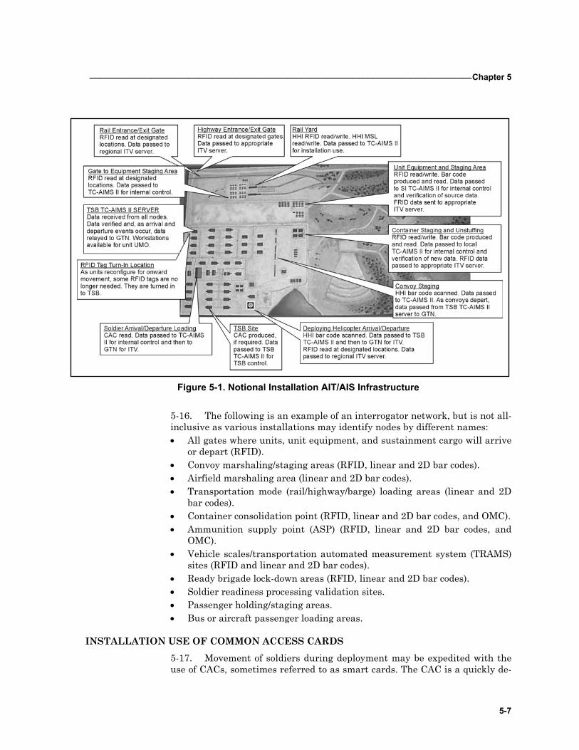
_________________________________________________________________________________Chapter 5
5-7
Figure 5-1. Notional Installation AIT/AIS Infrastructure
5-16. The following is an example of an interrogator network, but is not all-inclusive as various installations may identify nodes by different names: • All gates where units, unit equipment, and sustainment cargo will arrive
or depart (RFID). • Convoy marshaling/staging areas (RFID, linear and 2D bar codes). • Airfield marshaling area (linear and 2D bar codes). • Transportation mode (rail/highway/barge) loading areas (linear and 2D
bar codes). • Container consolidation point (RFID, linear and 2D bar codes, and OMC). • Ammunition supply point (ASP) (RFID, linear and 2D bar codes, and
OMC). • Vehicle scales/transportation automated measurement system (TRAMS)
sites (RFID and linear and 2D bar codes). • Ready brigade lock-down areas (RFID, linear and 2D bar codes). • Soldier readiness processing validation sites. • Passenger holding/staging areas. • Bus or aircraft passenger loading areas.
INSTALLATION USE OF COMMON ACCESS CARDS 5-17. Movement of soldiers during deployment may be expedited with the use of CACs, sometimes referred to as smart cards. The CAC is a quickly de-
FM 3-35.4 _________________________________________________________________________________
5-8
veloping enabler that, when fully implemented, will be accessible by AIS and enhance deployability. Installation responsibilities concerning the CAC will be further defined as the technology is integrated.
5-18. Installation consolidated SRP sites will eventually have the capabil-ity to produce/update common access cards. As soldiers complete the SRP process, their personal deployment information is encrypted onto a card. The CAC then captures movements as the soldier travels through the deployment process. CAC use eliminates the need for paper manifesting of soldiers as they board transportation moving from the installation to the POE.
BRIGADE EQUIVALENT 5-19. Home station is the permanent location of active and USAR component units. After receiving the alert or warning order of an impending deployment, the unit has AIS/AIT-related responsibilities at HS. All brigade equivalent units develop deployment plans. They may have several deploy-ment plans based on the contingency operations they support. Each plan may involve different task organizations of equipment, personnel, and accompany-ing supplies that the unit must deploy by a variety of modes. Before depar-ture from HS, the UMO creates a UDL in a TC-AIMS II deployment plan. The brigade equivalent headquarters or the supporting installation verifies the accuracy of the plan data and forwards the plan to the plans and opera-tions section of its higher headquarters. The higher headquarters imports the plan into the JFRG II. This file is then forwarded to the operations center that updates JOPES. The installation unit movement coordinator or move-ment control element produces a movement plan using TC-AIMS II and coor-dinates transportation support for the movement plan.
BATTALION AND SEPARATE COMPANY/UNIT 5-20. The UMO will use TC-AIMS II to create an accurate OEL that identi-fies all personnel equipment and supplies assigned to a unit identification code (UIC). The unit will produce source data using TC-AIMS II for AIT data storage devices (such as linear and 2D bar codes and RFID tags). The battal-ion and/or company/unit commander has the responsibility to ensure the source data is accurate and AIT storage devices are created.
5-21. The supply accountability bar code is scanned using the TC-AIMS II hand-held reader/interrogator as units load equipment into containers or build pallets. The hand-held reader/interrogator transfers the data to the TC-AIMS II computer. TC-AIMS II then generates a packing list and burns an RFID tag. The RFID tag contains a detailed list of all the unit equipment consolidated within the container. The RFID tag is attached to the consoli-dated shipment for ITV tracking. (See Appendix N for information on the ap-plication of linear and 2D bar codes and RFID tags to unit equipment.)
_________________________________________________________________________________Chapter 5
5-9
Bar code labels were missing from the majority of Kosovo Peacekeeping Force (KFOR) cargo arriving at the port. In addition, advanced data received from TC-ACCIS was inaccurate. All consignor and consignee fields were filled with the de-fault code of “111111” so the port operators could not use AIT or AIS to verify the unit that was shipping the equipment and the unit that would receive the equip-ment. Additionally, there were problems reading bar code labels because opera-tors were inputting the letter ‘O’ rather then the number ‘0’ in the transportation control numbers (TCN). This error caused WPS to reject the TCN. This rejection caused delays in passing the information from WPS to ICODS. These errors caused delays in stow planning and loading vessels while port documentation per-sonnel manually corrected the information problem.
Kosovo After Action Report
5-22. The UMO refines the UDL after receipt of the alert order or warning order before movement to the POE. The unit updates its load plans and pro-duces accurate MSLs and required RFID tags.
5-23. Deploying units properly label and tag their equipment and update AIS before beginning the deployment. By ensuring AIT data storage devices are accurate, properly attached to unit equipment, and readable, units facili-tate ITV with limited human intervention at the other transportation pipe-line nodes. Inaccurate data and manual data collection procedures for arriv-ing units at reception nodes slow the deployment process.
5-24. Units develop SOPs to support the readiness standard operating pro-cedures (RSOP). The RSOP specifies procedures, responsibilities, and quality controls for ensuring that all equipment is properly bar coded, to include lo-cation of MSLs on equipment and containers. The RSOP assigns responsibili-ties and procedures for using deployment AIS in the unit marshaling and staging area while preparing for deployment.
SECTION II – INSTALLATION SUPPORT EN ROUTE TO THE POE
5-25. Various installations in CONUS are assigned supporting installation missions within geographical areas of responsibility. ASGs or BSBs normally perform these missions during OCONUS deployments. The required en route support varies based on factors such as C2 requirements, distance to the POE and in-transit visibility requirements. There are no standards for en route ITV reporting established by the DoD AIT Implementation Plan. En route support missions may require maintenance or life support. If a support site manned rest halt, or convoy support center (CSC) is established, planners should consider collocating a TC-AIMS II system with fixed and hand-held readers/interrogators. This enables the site to capture the arrival and depar-ture of equipment and convoys moving to and from the port. For ITV re-quirements, supporting installations should also consider the feasibility of placing fixed interrogators at highway and rail choke points leading to POEs. This allows the data capture of RFID information as the equipment passes the interrogators. The installation’s AIT site survey should address en route AIT support requirements.
FM 3-35.4 _________________________________________________________________________________
5-10
5-26. Other en route AIT data collection options include— • Placing satellite transponders in selected vehicles (for example, the con-
voy commander’s vehicle and vehicles with sensitive items) and monitor-ing the movement via satellite.
• Using commercial carrier AIT with an electronic data interchange (EDI) feed to the GTN.
SECTION III – AERIAL PORTS OF EMBARKATION
5-27. APOE operations, by their very nature, cross Service boundaries for most force projection operations. The A/DACG is the primary organization responsible for Army operations at airfields. The arrival and departure of all unit equipment, personnel, and sustainment air cargo moving to and from APOEs must be captured in automated information systems and reported to GTN within one hour of occurrence. There are three primary organizations operating at the APOE that may possess AIT enabling tools: the Air Force element responsible for aircraft loading, the Army port movement control team (if established), and the Army departure airfield control group. Detailed inter-Service support agreements (ISSAs) or other arrangements should be established in advance of deployment operations detailing information flow through deployment AIS at the APOE. The arrangements address each or-ganization’s functions and responsibilities as they relate to information flows using deployment AIS. DACGs that come from TOE cargo transfer or cargo documentation elements are equipped with deployment AIS. Ad hoc DACGs may not have an organic deployment AIS. Supporting installations and com-mands providing ad hoc DACGs must plan for obtaining deployment AIS.
AIS PLANNING CONSIDERATIONS AT THE APOE 5-28. MACOMs, supporting installations (or the Army organizations re-sponsible for providing airfield support), and the Air Force element responsi-ble for APOE operations address deployment AIS considerations in advance of deployment operations. Two general considerations are— • Identifying the deployment AIS responsibilities for the marshalling area,
passenger-holding area, alert holding area, and call forward area. • Defining the procedures for processing information on Army equipment
and personnel arriving at the airfield.
5-29. Deployment AIS at aerial ports requires detailed planning and prior coordination to support ITV information requirements. Planners must estab-lish a system architecture to capture the arrival and departure of both pas-sengers and equipment through an APOE. (See Figure 5-2 for a notional dia-gram of AIS/AIT use at an APOE.)
_________________________________________________________________________________Chapter 5
5-11
Figure 5-2. Notional APOE with AIS/AIT Infrastructure
5-30. Planners address the following Army deployment AIS considerations for APOEs: • Coordinate with Air Force elements to augment the deployment AIS in-
frastructure at the APOE with Army elements operating at the APOE during force projection operations.
• Identify the deployment AIS that will contain the primary source data used to feed GTN. (AMC will use the Global Air Transportation Execu-tion System (GATES) or Remote GATES (RGATES)).
• Identify the communications requirements and restrictions at each par-ticular airfield that will affect the use of Army deployment AIS.
PASSENGER MOVEMENTS THROUGH AN APOE 5-31. Passengers moving through an APOE usually process through two distinct areas: the marshaling area and the passenger holding area. Marshal-ing areas may be located at the home installation, at the APOE, or in both lo-cations depending on the deployment scenario and distances.
5-32. The installation or base commander usually establishes the marshal-ing area as close as possible to the APOE. However, marshaling activities may be conducted within the deploying unit’s permanent area. Both the unit and the organization responsible for supporting operations at the marshaling area have AIS-related responsibilities.
FM 3-35.4 _________________________________________________________________________________
5-12
5-33. The unit verifies personnel manifests and ensures all soldiers have accurate and up-to-date CACs, when available. The army command control-ling the marshaling area (may be a supporting installation, DACG, or other designated unit/command)— • Scans arriving soldier’s CACs for internal accountability and for ITV re-
porting requirements, if the marshaling area is on the air base. If this is the initial arrival area for soldiers at the APOE, procedures must be in place to report this data to GTN within one hour of the arrival, in accor-dance with the DoD AIT Implementation Plan standards.
• Assists the unit in correcting any CAC deficiencies. • Scans all CACs and matches the data against the manifest as soldiers
depart the marshaling area for the passenger holding area.
5-34. Normally a distinct passenger holding area is established near the APOE. The Air Mobility Command or other Air Force elements operate the passenger holding area. Soldiers arriving from the marshaling area link up with soldiers assigned duties loading unit equipment aboard the aircraft. As soldiers arrive, the DACG, or other supporting Army elements, verify per-sonnel information against the unit manifest. The DACG assists in making any final manifest corrections. When notified, the DACG passes control of deploying soldiers to the Air Force element along with an electronic copy of the personnel manifest. The Air Force element loads this electronic data into GATES or R-GATES and passes departure data to GTN within one hour of aircraft takeoff.
UNIT EQUIPMENT MOVEMENTS THROUGH AN APOE 5-35. Normally unit equipment passes through four distinct areas when deploying through an APOE: marshaling area, alert holding area, call-forward area, and ready line/loading areas. Organizations have overlapping responsibilities in each of these locations; they should set procedures before operations begin.
MARSHALING AREA 5-36. An equipment marshaling area can be on the installation, near the airfield, or in both locations depending on the deployment situation. Not all deployments require the establishment of a marshaling area at the APOE. Based on the deployment timeline, distance between the HS and the APOE, space requirements, and marshaling space available at the APOE, a mar-shaling area may be established near the port facility for equipment consoli-dation. The supporting installation or area support group whose geographical area of responsibility controls the area around the port complex normally op-erates the marshaling area.
_________________________________________________________________________________Chapter 5
5-13
5-37. Deploying units, with installation or other designated support ele-ment assistance, are responsible for ensuring their equipment is properly prepared for onward movement before it departs the marshalling area. Key deployment AIS considerations at the marshaling area are as follows: • The unit—
Ensures all equipment still has the correct label and/or RFID tag and that none of the AIT data storage devices (for example, linear and 2D bar codes, MSLs, and RFID tags) have been damaged in transit.
Verifies that bar codes and RFID tags are properly attached to pre-clude loss or damage during further movement.
Verifies that all MSLs are readable. (This procedure requires a TC-AIMS II hand-held scanner.)
• The Army command responsible for marshaling area operations— Captures the arrival and departure of all unit equipment and sus-
tainment cargo at the marshaling area. Provides additional RFID batteries for emergency replacement. Assists units as necessary.
5-38. The unit corrects any problems or deficiencies found with AIT data storage devices before the equipment is moved from the marshalling area. If the unit does not have the capability to make corrections, the supporting in-stallation or designated unit supporting the deployment provides support. Af-ter preparing their equipment for air movement, units arrange vehicles and equipment in chalk order before movement to the alert holding area.
ALERT HOLDING AREA 5-39. The alert holding area is normally on the airfield and controlled by the DACG. The DACG coordinates operations between the unit and the Air Force element (normally a TALCE) conducting aircraft loading. The DACG scans the MSLs of all arriving and departing equipment for internal DACG accountability and control purposes. The DACG is responsible for verifying that MSLs and RFID tags are properly attached to the piece of equipment or pallet to preclude damage or loss during air movement and for scanning all MSLs to ensure they are readable.
5-40. The supporting command may need to resource the DACG with the capability to check the battery life in all RFID tags and have them replaced, if necessary. Once unit equipment is ready, it is moved from the alert holding area to the call-forward area.
CALL-FORWARD AREA 5-41. The call-forward area of the airfield is where the unit and Air Force element conduct joint inspection of equipment and air load plans are devel-oped in the automated air load planning system (AALPS). The call-forward area is under the control of the DACG (or designated Army element). The unit, with assistance from the DACG, corrects all deficiencies found during joint inspections.
FM 3-35.4 _________________________________________________________________________________
5-14
READY LINE/LOADING AREA 5-42. The ready line/loading area is under the operational control of the Air Force. The DACG passes the AALPS load plans and control of Army unit equipment to the Air Force at the ready line. The Air Force imports the AALPS load plans into GATES, ensures that the aircraft is loaded properly, and sends aircraft departure and ITV data to the GTN within one hour of air-craft departure.
SECTION IV – SEAPORTS OF EMBARKATION
5-43. SPOE operations cross Service boundaries as equipment is loaded on strategic transport for overseas movement. The primary organization respon-sible for SPOE operations is MTMC. MTMC is the military port manager for all common-user water terminals. Also operating in the port complex will be MSC, PSA, and the unit. Other possible operators at the port are civilian port managers and operators, and possibly, Army port operators (7th Transporta-tion Group or a USAR transportation group). Depending on the location, there may also be an Army port movement control team. MTMC, as the DoD designated single port manager for all worldwide common user seaports, co-ordinates operations between Army units and MSC. If required, MTMC will also coordinate all activities with the civilian port authorities and operators.
5-44. Unit equipment transiting an SPOE generally passes through two primary areas before vessel loading: a marshaling area normally located just outside the port and a staging area located within the port. Depending on the size of the operation and the amount of unit equipment passing through the SPOE, a marshaling area may or may not be established. The primary pur-pose of a marshaling area is to provide a location near the port complex to as-semble unit equipment and sustainment cargo and make final preparations for ocean shipment just before entering the port. Marshaling areas are often established when the volume of materiel moving to the port exceeds internal port capabilities. In CONUS, FORSCOM has designated supporting installa-tions to provide marshaling area and PSAs to MTMC terminals. In OCONUS operations, the theater commander establishes a similar relationship with MTMC.
AIS PLANNING CONSIDERATIONS AT THE SPOE 5-45. The primary use of AIT in deployment AIS at the port complex is to capture information for ITV reporting and for internal control. Both MTMC and the PSA use AIT to capture the movement of unit equipment through the port complex. AIT can also be used to locate RFID tagged unit equipment that is in the port area.
5-46. The PSA and MTMC elements operating in the SPOE have a limited capability to verify data on AIT media and a limited capacity to make correc-tions. Deploying units should not expect the SPOE to have a capability to properly label and tag their equipment. This is a unit and installation func-tion.
5-47. Supporting installations should provide deployment AIS to the PSAs.
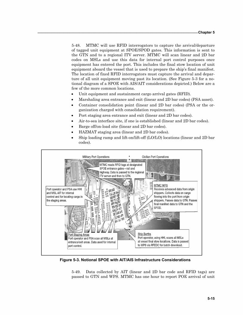
_________________________________________________________________________________Chapter 5
5-15
5-48. MTMC will use RFID interrogators to capture the arrival/departure of tagged unit equipment at SPOE/SPOD gates. This information is sent to the GTN and to a regional ITV server. MTMC will scan linear and 2D bar codes on MSLs and use this data for internal port control purposes once equipment has entered the port. This includes the final stow location of unit equipment aboard the vessel that is used to prepare the ship’s final manifest. The location of fixed RFID interrogators must capture the arrival and depar-ture of all unit equipment moving past its location. (See Figure 5-3 for a no-tional diagram of a SPOE with AIS/AIT considerations depicted.) Below are a few of the more common locations. • Unit equipment and sustainment cargo arrival gates (RFID). • Marshaling area entrance and exit (linear and 2D bar codes) (PSA asset). • Container consolidation point (linear and 2D bar codes) (PSA or the or-
ganization charged with consolidation requirement). • Port staging area entrance and exit (linear and 2D bar codes). • Air-to-sea interface site, if one is established (linear and 2D bar codes). • Barge off/on-load site (linear and 2D bar codes). • HAZMAT staging area (linear and 2D bar codes). • Ship loading ramp and lift-on/lift-off (LO/LO) locations (linear and 2D bar
codes).
Figure 5-3. Notional SPOE with AIT/AIS Infrastructure Considerations
5-49. Data collected by AIT (linear and 2D bar code and RFID tags) are passed to GTN and WPS. MTMC has one hour to report POE arrival of unit
FM 3-35.4 _________________________________________________________________________________
5-16
equipment by WPS to GTN, and four hours to report POE arrival of sustain-ment cargo.
CARGO MOVEMENTS THROUGH SPOE 5-50. Normally unit equipment and sustainment cargo moves through a marshaling and port staging area before it is loaded on a vessel.
MARSHALING AREA 5-51. Not all deployments require the establishment of a marshaling area at the SPOE. If a marshaling area is established, the supporting installation or ASG whose geographical area of operation controls the area around the port complex normally runs it. SPOE responsibilities should be identified during planning and coordination before any deployment operations are exe-cuted. The key deployment AIS/AIT considerations at the marshaling area are— • Capturing the movement of all unit equipment and sustainment cargo
arriving and departing the area. • Verifying AIT data storage devices are properly affixed to the equipment.
5-52. Units should correct problems found with AIT data storage devices. If the unit is not located in the marshaling area, the organization operating the marshaling area should make these corrections.
PORT STAGING AREA 5-53. The staging area is the final location where equipment is assembled before loading the vessel. Equipment is usually lined up by piece type, or in the order that it will be moved onto the ship. MTMC and the PSA both oper-ate in the staging area. The key deployment AIS/AIT functions in the staging area are— • Scanning or interrogating all unit equipment and sustainment cargo as it
arrives and leaves the staging area. • Producing new AIT data storage devices for any pieces of equipment that
have damaged, inaccurate, or missing RFID tags or MSLs.
VESSEL LOADING 5-54. MTMC controls all equipment departing the staging area for vessel loading. Normally the equipment is scanned at the final stowage location. Scanned data is passed to the WPS. WPS then uses an electronic data inter-change transaction and sends the ship’s final manifest to the GTN and the SPOD WPS. For unit movements, this data must be visible in GTN within one hour of ship departure. For sustainment shipments, that data must be visible in GTN within four hours. MSC reports ship departure from the port complex.
_________________________________________________________________________________Chapter 5
5-17
PASSENGER MOVEMENTS THROUGH A SPOE 5-55. A final consideration for AIS/AIT uses at the SPOE is the possible need for a plan to capture personnel movements by ocean transport. This need may occur with— • Large-scale mobilization and the use of passenger ships. • Soldiers moving on Navy ships (similar to the United States Marine
Corps [USMC]). • Self-deploying U.S. Army watercraft. • Supercargoes accompanying Army equipment.
5-56. There are several options that planners should consider for using AIT to capture the movement of Army personnel through water terminals: • Establish an ISSA with MTMC to ensure that a MTMC element has TC-
AIMS II available at SPOEs where a large number of Army personnel will deploy.
• Develop an ISSA with the Navy to use its TC-AIMS II system to capture the movement of Army personnel deploying on Navy vessels.
• Equip the port support activity TC-AIMS II system with CAC read capa-bility to capture movements. This option assumes that the PSA has a TC-AIMS II capability.
• Ensure self-deploying Army watercraft use their battalion-level TC-AIMS II system to capture and report their personnel movement.
• For small numbers of supercargoes, have the supercargoes call their com-mand before vessel departure. The parent command then uses the TC-AIMS II data feed to GTN to provide passenger movement information.

A-1
Appendix A
Automation and Communication Systems
The rapid advance of web-based technology provides combatant and com-ponent commands potential worldwide access to various references and information to enhance deployment and redeployment operations. (The systems described below use web-based technology only where stated in the text.) This appendix presents an overview of automated and commu-nication support systems that may be available to deploying units/organizations. If required, these systems obtain and transmit unit movement requirements in support of operations and to monitor execu-tion.
JOINT OPERATION PLANNING AND EXECUTION SYSTEM A-1. The Joint Operation Planning and Execution System (JOPES) is the system used by the JPEC to conduct joint planning during peace and crisis. (See Figure A-1.) Joint operation planning is a process coordinated through all levels of the national structure for joint planning and execution, including the NCA and the JPEC. The focus of the joint operation planning process is the combatant commanders users, assisted by and coordinated through JOPES, to determine the best method of accomplishing assigned tasks and to direct the actions necessary to accomplish the mission. In normal peacetime conditions, the deliberate planning process produces operation plans, either OPLANS or CONPLANs, and functional plans. In crises, CAP produces OPORDs. JOPES’ focus is on force generation and tracking. Building force requirements, capturing/scheduling strategic lift requirements and execution reporting, within the JOPES accomplish this. Senior-level decision-makers use JOPES to plan and execute deployment, sustainment, and redeployment activities. It supports the national, theater, and supporting organizational levels in both peacetime and crisis. For additional information (See CJCSM 3122.03).
A-2. The JOPES has two end products (OPLANs and OPORDs). OPLANs are the result of deliberate planning conducted during peacetime. OPORDs are the execution portion of an OPLAN. FRAGOs are a result of time-sensitive planning.
FM 3-35.4 ________________________________________________________________________________
A-2
Figure A-1. Joint Operation Planning and Execution System
A-3. The JOPES planning is based on both requirements and capabilities. Military planners use forces and resources identified in the Joint Strategic Capabilities Plan (JSCP), CJCS orders, Service documents, and approved OPORDs. They identify forces and resources required to accomplish the mis-sion and compare them to actual forces and resources available. Supporting commands and agencies and the Services confirm force and resource avail-ability, including combat, combat service and combat service support forces, and transportation resources. Rapid, accurate exchange of information is fundamental to the intense coordination required throughout the JPEC to support timely decisions during planning and to adjust operations to the de-veloping situation during execution.
A-4. Within JOPES, completed and approved plans are maintained and updated as changes in the plans occur. Development of new plans occurs, when the threat, tasks, forces assigned, resources available, and/or concept of operations change to the extent that the supported commander and the Chairman of the Joint Chiefs of Staff determine necessary. Otherwise, com-manders and their staffs concentrate on keeping existing plans and orders up to date and executable through use of all appropriate methods, including plan maintenance conferences and plan-specific newsgroups.
_______________________________________________________________________________ Appendix A
A-3
GLOBAL TRANSPORTATION NETWORK A-5. The Global Transportation Network (GTN) is the USTRANSCOM automated command and control information system that supports transpor-tation users and providers, both DoD and commercial, in an integrated sys-tem providing command and control and ITV capabilities. GTN collects and integrates transportation data from selected transportation systems. The re-sulting data is provided to the NCA, commanders-in-chief (CINCs), USTRANSCOM, its component commands, and DoD customers to support transportation planning and decision making during peacetime and wartime. GTN supports planning, providing, and controlling the common user airlift, surface lift, and terminal services that deploy and support DoD forces glob-ally during peacetime and wartime. Specifically, GTN focuses on providing USTRANSCOM with the information necessary for visibility, planning, command and control, intelligence, and reporting.
A-6. Although not a JOPES system, GTN is a GCCS interface that pro-vides information essential to monitoring and managing TPFDD execution. GTN furnishes the automated command and control support needed for USTRANSCOM to carry out its mission of global transportation management for DoD. GTN also supports USTRANSCOM in accomplishing its task to in-tegrate deployment-related automatic data processing systems and to furnish centralized ITV in peace and war.
A-7. GTN accesses current transportation information from diverse sources, integrates that information, and gives it to users in a useful form. Information is integrated into a central database to cross-reference supply, cargo, forces, passenger, and patient requirements and movements with air-lift, air refueling, aero-medical, and sealift schedules and movement.
A-8. GTN gives users the ability to do the following— • Locate items in transit • Forecast port workload • Assess unit deployment status • Determine onward movement requirements • Determine container and pallet contents • Obtain current aircraft and ship schedules
GLOBAL COMMAND AND CONTROL SYSTEM A-9. The Global Command and Control System (GCCS) with its Service subset, the GCCS-A, has replaced the Worldwide Military Command and Control System. GCCS is a system of interconnected computers that provides integrated command, control, communications, computers and intelligence (C4I) capability to the joint community. It provides information from a variety of applications that have migrated, or are in the process of migrating, from other systems including JOPES. GCCS can document movement re-quirements, transportation closures, and other significant deployment-related events. Pre-formatted reports containing information on deployment requirements and strategic lift schedules are available on GCCS. Any regis-tered GCCS user using the Rapid Query Tool (RQT) software can also extract requirements and scheduling information. This software establishes site-
FM 3-35.4 ________________________________________________________________________________
A-4
unique reports merging both requirements and scheduling information. The JOPES Editing Tool (JET), a major application on GCCS, allows operators and planners the ability to rapidly edit and analyze a TPFDD. The Joint Flow and Analysis System for Transportation (JFAST), is a JOPES related GTN application that allows planners to establish transportation feasibility deployment data.
A-10. The GCCS provides a fused picture of the battlespace within a mod-ern command, control, communications, and computers system capable of meeting Warfighter needs into the 21st century. It incorporates the core planning and assessment tools required by the combatant commanders and their subordinate joint force commanders and meet the readiness support re-quirements of the Services. GCCS is required to move the combatant com-manders and subordinate joint force commanders joint command and control support capability into the modern era of client/server architecture using commercial, open systems standards for both commercial and government off-the-shelf applications. The essential umbrella standards and unifying ap-proach that GCCS brings to the ongoing DoD command, control, communica-tions, computers, and intelligence system migration strategy for the Services and agencies can successfully reduce the large number of systems in use to-day.
GLOBAL COMMAND AND CONTROL SYSTEM-ARMY A-11. The Global Command and Control System-Army (GCCS-A) is the Army component system that directly supports implementation of the joint GCCS and provides the echelons above corps (EAC) portion of the Army Bat-tle Command and Control System. GCCS-A supports operations from peace to war, including contingency and stability or support operations, and force projection. It supports the Army component commands, combatant com-manders, Army JTF commands and components, and HQDA. GCCS-Army is tailored to Army-specific information management needs.
END-TO-END FORCE TRACKING A-12. End-to-End Force Tracking (EEFT) is a GCCS-Army module that al-lows the commander to visualize the flow of forces into a theater in accor-dance with the TPFDD and to perform force tracking. This system is modeled after the Standard Theater Army Command and Control System, an USAEUR-unique command and control system.
GLOBAL DECISION SUPPORT SYSTEM A-13. The Global Decision Support System (GDSS) is the worldwide com-mand and control (C2) system for executing strategic lift and air refueling. It contains essential information used to monitor and manage all operational DoD air mobility missions in progress throughout the world. It provides automated tools to track aircraft and aircrew movement.
_______________________________________________________________________________ Appendix A
A-5
COMBAT SERVICE SUPPORT CONTROL SYSTEM A-14. The Combat Service Support Control System (CSSCS) provides force-level commanders and planning staffs with an automated capability to gen-erate a common picture of the battlefield, the CSS status, and courses of ac-tion (COA) planning. The system products are tailored to the information needs of the various force-level commanders. It facilitates the required data flow from mobilization through deployment and redeployment to demobiliza-tion.
A-15. Echelons Above Corps-Combat Service Support Control System (EAC-CSSCS) applications will eventually be provided in the GCCS-Army. They will provide commanders and planning staffs with automated capability to generate a common picture of the battlefield, the CSS status, and COA planning. EAC-CSSCS will also provide commanders and staffs with detailed information on the mobilization, deployment, redeployment, and demobiliza-tion status of specified units.
COMPUTERIZED MOVEMENTS PLANNING AND STATUS SYSTEM A-16. Computerized Movements Planning and Status System (COMPASS) is an Army command and control support system that uses evolving com-puter technology with multiple system interfaces. It facilitates collection and maintenance of UMD to support planning, strategic mobility analysis, movement execution, and command and control for mobilization and deploy-ment purposes. The Army uses the COMPASS to satisfy CINC, Army, and joint staff UMD information requirements for deliberate, crisis action plan-ning, strategic mobility analysis, and mobilization and deployment move-ment execution. The COMPASS processed UMD is utilized within the JOPES. The current COMPASS uses direct interfaces with the GCCS-Army, Army Status of Operational Readiness and Training System (ASORTS), and the Mobilization, Operations, Deployment, Employment and Execution Sys-tem (MOB/ODEE), as its primary sources of unit movement data to satisfy command information needs for deployment.
JOINT FORCE REQUIREMENTS GENERATOR A-17. The Joint Force Requirements Generator (JFRG II) is an automated computer-based planning tool designed to support the Services in the devel-opment of both deliberate and crisis action plans. It supports tactical and administrative planning by providing the following capabilities: import of Service type unit characteristic (TUCHA) data, rapid force list creation, lift analysis, TPFDD development/manipulation, and import/export to the JOPES. JFRG II is an information system used to provide UDLs from units through the Service’s logistics automation information systems (currently TC-ACCIS for the Army and the Marine Air-Ground Task Force II system (MAGTF II) for the Marine Corps) to JOPES.
WORLDWIDE PORT SYSTEM A-18. The Worldwide Port System (WPS) is a single standard AIS desig-nated to support the function of cargo documentation, accountability and
FM 3-35.4 ________________________________________________________________________________
A-6
management at common user ocean terminals associated with MTMC, U.S. Navy, USFORSCOM, active and USAR automated cargo documentation detachments, transportation groups, battalions, and brigades. WPS supports the operation of common user water terminals worldwide, during peacetime and wartime operations. WPS automates the information management func-tions of a military ocean port operation. It can document the import and ex-port of military cargo and develop appropriate documentation. The WPS pro-vides— • The ability, at the ocean terminals, to document cargo moving through a
port (manifests, TCMDs, and customs documentation). • The ability, at the ocean terminals, to account for and monitor the move-
ment of cargo through the port. • The ability to supply terminal and regional commanders the information
necessary to manage the movement of ocean cargo. • The ability to provide ITV information to other DoD systems. • The ability to use GTN to supply ITV of unit equipment.
TRANSPORTATION COORDINATOR-AUTOMATED COMMAND AND CONTROL INFORMATION SYSTEM
A-19. The Transportation Coordinator-Automated Command and Control Information System (TC-ACCIS) is the current information management and data communications system that Army units use to plan and execute de-ployments. TC-ACCIS aids the processing of mobility requirements and the flow of information to USTRANSCOM components. TC-ACCIS users include commanders, ITOs, division transportation officers (DTOs), and unit move-ment officers. TC-ACCIS is the United States Army's automated manage-ment information system designed to support the deploying units and instal-lation transportation offices in their efforts to provide timely and accurate movement data to the joint deployment community. It has a direct interface with FORSCOM’s COMPASS and through COMPASS to the JOPES. TC-ACCIS also supplies information to the MTMC IBS for surface moves and to the Logistics Support Activity's Logistical Intelligence File for in-transit and total asset visibility of Army unit movements. TC-AIMS II will replace TC-ACCIS as the primary interface for UMD data.
A-20. TC-ACCIS automates most transportation functions at the unit and installation level. It supports the unit’s deployment mission by— • Maintaining unit equipment lists. • Maintaining UDLs. • Preparing GBLs. • Preparing vehicle load cards. • Preparing vehicle/container packing lists. • Preparing advanced TCMDs (DD Form 1384). • Preparing convoy march tables. • Preparing convoy clearance reports (DD Form 1265). • Preparing special handling permits (DD Form 1266). • Preparing unit equipment manifests. • Preparing executable rail load plans.
_______________________________________________________________________________ Appendix A
A-7
• Maintaining blocking, bracing, packaging, crating and tie-down (BBPCT) material requirements lists.
• Preparing rail load schedules. • Interfacing with the AALPS.
TRANSPORTATION COORDINATORS' AUTOMATED INFORMATION FOR MOVEMENT SYSTEM II
A-21. The Transportation Coordinators' Automated Information For Move-ment System II (TC-AIMS II) will be the single DoD system supporting all unit and non-unit installation deployments, redeployments, and retrograde requirements, once fully fielded. TC-AIMS II interfaces with virtually all the current and planned deployment support automated systems. It will be fielded to units and installations worldwide and will perform two principal functions: unit movement and ITO/transportation management office opera-tions. Details on how TC-AIMS II will be employed by units will be in FM 4-01.011 (55-65).
A-22. The TC-AIMS II program addresses a critical shortfall in the move-ment of materiel and personnel in support of DoD transportation operations. TC-AIMS II falls within the DoD mission area supporting mobility and transportation of DoD personnel and cargo. TC-AIMS II provides UMOs, em-barkation officers, ITOs and traffic management offices (TMOs) throughout the DoD with a single, effective and efficient AIS to support transportation management of unit movement, passengers, and cargo during day-to-day and crisis operations within the DTS.
A-23. TC-AIMS II is the result of a joint effort of the U.S. armed forces and the JPMO, headed by the U.S. Army as the executive agent. TC-AIMS II pro-vides automated support to functions performed by UMOs and ITOs, who previously used a variety of Service automated systems and manual proc-esses. TC-AIMS II’s goal is to improve and expedite unit movements and TCC actions, providing timely and accurate information for use at all joint deployment community command levels in support of CONUS, OCONUS and in-theater JRSO&I operations.
A-24. To support these wide-ranging missions, TC-AIMS II will be provided to all installation transportation offices, nearly every battalion and separate company, and almost all U.S. Army transportation units and staff elements. Each of these organizations will use TC-AIMS II in the performance of both daily operations and deployments. TC-AIMS is installed on Service-provided hardware. It includes software and processes that support unit movement and sustainment transportation functions, and it provides access to various load-planning functions. These capabilities are available to the TC-AIMS II user from a client/server network, or a stand-alone configuration, at the unit/installation level. Whether in garrison or deployed using the ITV capa-bility of GTN, decision makers at various command levels have the ability to track and process data received from TC-AIMS II.
A-25. The Army’s goal for TC-AIMS II is to provide a system that supports the information needs of deploying unit commanders and deployment man-agers. TC-AIMS II will support these two key players in the Army’s critical
FM 3-35.4 ________________________________________________________________________________
A-8
mission of deployment. Deploying commanders and their staff will use TC-AIMS II to translate information about the mission into detailed and realistic movement plans for the deployment. This translation occurs in a short time frame—capturing the continual changes to available lift assets, mission de-tails, and unit assets allocated to support the mission.
A-26. Deployment managers (acting for commanders) will use TC-AIMS II to—
• Coordinate strategic lift missions via air and water.
• Schedule unit convoy movements.
• Schedule interrelated deployment events.
• Prepare load plans for vehicles, rail cars, aircraft or ships.
• Prepare DTR/Electronic Data Interchange (EDI) documentation.
• Account for equipment, personnel, and consumable supplies.
Deployment managers (acting for commanders) use TC-AIMS II for docu-menting paper authorization to expend funds and validate services. This sys-tem provides a common, accurate deployment picture to both elements and includes software that has the ability to perform the following functions when enabled by the appropriate permissions: • Prepare load plans. • Read/write AIT devices (for example, RF tags, MSLs, CACs). • Order transport services. • Coordinate convoy clearances. • Produce passenger manifests (via interface with personnel management
systems and via manual means if interface not available). • Account for the receipt and loading of unit equipment at marshal-
ling/assembly areas. • Account for movement to ports of embarkation, unit loading on strategic
lift assets, reception at ports of debarkation, and onward movement to staging areas and TAA.
• Create transportation control and movement document (TCMD) data. • Create GBL and freight warrants. • Manage the deployment schedule (planned versus actual event times).
A-27. Sharing information with both supporting and supported Army ele-ments is an UMO responsibility usually considered an additional duty for the officer or non-commissioned officer (NCO), rather than a documented unit TOE position. TC-AIMS II provides the UMO with the integrated informa-tion management tools needed to achieve success in this area. Functions that the UMO accomplishes using TC-AIMS II include— • Extracting unit personnel and equipment records from standard Army
systems. • Preparing UDL identifying equipment, personnel and basic
load/sustainment items for deployment/movement.
_______________________________________________________________________________ Appendix A
A-9
• Planning convoy movements and proposing convoy routing for movement to ports of embarkation.
• Preparing load plans and manifests for aircraft, rail, and barge move-ments.
• Preparing individual vehicle load plans and generating approved load cards for each vehicle.
• Creating DTR-approved shipping documentation, hazardous material (HAZMAT) documentation and military shipment labels for all deploying equipment.
• Preparing RF tags for major equipment items/containers. • Developing an internal deployment schedule and recording deployment
events as they occur. • Reporting unit-level deployment information to higher headquarters. • Allowing merging of deployment information at higher headquarters
level. • Requesting transport services from ITO or movement control personnel.
A-28. The basis of issue for TC-AIMS II hardware/software and AIT reader/writer devices will be battalion and separate company level. The headquarters and headquarters company/headquarters and headquarters troop (HHC/HHT) at groups, regiments, brigades, and similar organizations require the system to support the deployment of the headquarters elements. Many units receive AIT devices in the form of reader/writers that support bar code technology, RF tags, and optical memory cards. TC-AIMS II use com-mercial off-the-shelf notebook computers to support the UMO mission. The computers include Personal Computer Memory Card International Associa-tion (PCMCIA) cards (PC cards) to support communications using modem and connectivity to a local area network (LAN). The TC-AIMS II equipment for separate companies and HHCs allocates to the Company Command Sec-tions.
A-29. TC-AIMS II supports the UMO in managing deployment data, creat-ing deployment plans and monitoring deployment status throughout all phases of the deployment. The system supports daily operations in the instal-lation and pre-deployment planning activities, actions needed to move the unit increments to the POE or to exercise areas, and unit actions to move the unit increments from the POD to the TAA. The TC-AIMS II notebook com-puter gives UMOs the full capability on one system that they now must exe-cute on separate AALPS and TC-ACCIS computers. The one system permits the UMO to deploy the entire unit through multiple movements without hav-ing to re-enter data for each new step in the deployment process.
A-30. The higher headquarters for a deploying unit provides guidance to the deploying unit about the type mission it is to execute upon deployment. Higher headquarters also provides guidance on the commander’s intent for how that mission executes, and the factors considered in setting the deploy-ment sequence/priorities. The headquarters staff develops, interprets and re-lays this guidance and ensures it is followed. Although this discussion fo-cuses on the operations officer (S3) and logistics officer (S4), it applies to the entire staff. The headquarters is responsible for the successful deployment of
FM 3-35.4 ________________________________________________________________________________
A-10
its subordinate units. While the headquarters itself may deploy, these actions occur.
A-31. The staff elements served by TC-AIMS II deployment processing software are the S3 and S4 staff. TC-AIMS II provide the tools to allow these staff elements to— • Accomplish the same tasks outlined for the battalion/separate company
UMO. • Consolidate equipment/personnel and sustainment supply lists for all
subordinate and supporting units into a battalion, group, brigade, or task force deployment plan.
• Review and direct changes to deployment plans created by subordi-nate/task force units.
• Forward a consolidated battalion, group, brigade, task force or similar deployment plan to the TC-AIMS II server at the division, COSCOM, corps, or ITO where command/installation deployment managers can re-view it, consolidate it with other plans, and procure transportation ser-vices to execute the plans.
• Prepare a deployment schedule of events/flow table to use as a manage-ment tool. The flow table establishes time frames for events to occur, re-cord the times that events occur, and assess the deployment status.
• Receive TPFDD information from command/installation deployment managers and record the information that completes the TPFDD.
• Maintain unclassified record copies of deployment plans for exercises and contingencies. When the headquarters is alerted to deploy, review and update these record copies to form a template for the deployment.
A-32. Each U.S. Army battalion and higher headquarters is required to re-ceive TC-AIMS II software, two computers (S3 and S4), and AIT equipment. The S3 staff is responsible for defining the deployable force and the se-quence/priority for the deployment increments. This definition is an evolving process, as more information is known about the mission parameters. The S3 staff must know what is happening with the deployment and must provide new guidance approved by the commander when more is known about the mission. The S4 staff is responsible for creating and executing a deployment plan that meets the commander’s mission objectives. For complete success, both the S3 and S4 staffs need to know the same things about the deploy-ment at the same time.
AUTOMATED AIR LOAD PLANNING SYSTEM A-33. The Automated Air Load Planning System (AALPS) is a computer-ized system used to produce air manifests. UMOs, deployment planners, and contingency planners/force designers use it to plan and execute air movement as well as to design and analyze force packages. It operates with DEL data from TC-ACCIS, (UDL data when AALPS is integrated with TC-AIMS), or in a stand-alone configuration. AALPS can— • Rapidly estimate airlift requirements for a given deployment list. • Build, store, and maintain pre-planned contingency packages. • Provide automated assistance to produce individual aircraft load plans.
_______________________________________________________________________________ Appendix A
A-11
A-34. AALPS allows military air load planners to quickly and efficiently es-timate airlift requirements, plan force packages, and modify aircraft loads. AALPS rapidly provides estimates of airlift requirements for a given list of equipment and passengers and takes into account the unique loading re-quirements for the delivery methods used on all U.S. military and Civil Re-serve Air Fleet (CRAF) cargo aircraft. AALPS allows users to create and save contingency force packages in advance of a mission. This saves time and avoids input errors during deployment. The system has the capability to print approved load plans as well as various load and movement reports.
AUTOMATED MOVEMENT FLOW TRACKING SYSTEM A-35. The Automated Movement Flow Tracking System (AMFT) is an in-stallation-level system that provides deploying unit commanders and staffs with continuously updated deployment status. It provides a tool to plan movements of unit equipment and personnel through the successive installa-tion processing points to meet load-out schedules. AMFT provides the ability to uniquely define critical deployment events, and timing parameters re-quired by the installation in order to create schedules for critical movement, coordination and notification events supporting large deployments and/or daily missions. Through various system interfaces (AALPS, TC-AIMS-II, TC-ACCIS and TPS), AMFT can also provide visibility of specific equipment and personnel moving through the deployment process.
DEPARTMENT OF THE ARMY MOVEMENT MANAGEMENT SYSTEM A-36. The Department of the Army Movements Management System (DAMMS) Block III provides managers within the theater visibility of im-port, export, and intra-theater cargo movements. It provides mode managers asset accountability and asset visibility. Data provided to movement manag-ers, mode operators, and materiel managers expedites the onward movement of cargo and personnel.
A-37. The DAMMS Block II provides convoy planning and highway sched-uling. DAMMS allows the user to create main supply routes (MSRs) and to display map data in support of convoy planning and highway scheduling, us-ing a Graphic Information System (GIS). Units create convoys and submit requests for convoy clearance using the convoy planner. Requests are trans-mitted to a highway scheduler for de-conflicting, scheduling, and approval. TC-AIMS II shares the information.
JOINT FLOW AND ANALYSIS SYSTEM FOR TRANSPORTATION A-38. The Joint Flow and Analysis for Transportation (JFAST) is a per-sonal computer (PC)-based analysis tool for estimating transportation flows of deployment/redeployment. JFAST provides a means of performing COA development and analysis of deliberate planning, exercise, and real-world transportation problems.
FM 3-35.4 ________________________________________________________________________________
A-12
INTEGRATED COMPUTERIZED DEPLOYMENT SYSTEM A-39. The Integrated Computerized Deployment System (ICODES) is a shipload planning software application that uses artificial intelligence (AI) principles and techniques to assist embarkation specialists in the rapid de-velopment of cargo stow plans. It includes expert agents with knowledge in specific domains (for example, hazardous material handling, trim and stabil-ity, ramps, cranes, and internal access paths) to evaluate and propose loading alternatives and recommendations. ICODES integrates with information management and documentation systems such as WPS, TC-AIMS II, and IBS to receive cargo lists and send completed load plans. IBS operates from a PC and provides load-planning assistance to support deployment/redeployment by vessel. The accuracy of ICODES depends on the accuracy of the UDL. ICODES’ main functions are to calculate trim and stability; develop pre-stow plans; prepare final stowage plans for cargo loading; develop load diagrams; track cargo placement; prioritize discharge of cargo; and develop railcar, con-tainer, and flatrack load plans.
INTEGRATED BOOKING SYSTEM A-40. The Integrated Booking System (IBS) is the lead execution system of the DTS for the booking of international surface cargo. The system supports traffic management within MTMC, the greatest percentage of which is book-ing non-unit peacetime cargo. IBS must also satisfy the MTMC mission to execute the strategy developed in deliberate planning for international cargo. In addition, the system is responsible for booking cargo during contingency operations. IBS must respond to requirements of commodity managers and war planners requiring continuous access to international surface cargo movement. IBS is fielded to both CONUS and OCONUS booking locations. It exchanges data with WPS and other systems. IBS consolidates the cargo booking function into a single architecture and supports the function of book-ing movement requirements for sealift against available ocean cargo vessels. IBS supports the DTS in peace and wartime for deployments, redeployments, and sustainment cargo bookings.
ENHANCED LOGISTICS INTRATHEATER SUPPORT TOOL A-41. The Enhanced Logistics Intratheater Support Tool (ELIST) is a feasi-bility planning and modeling system fielded by MTMC for deployment analy-sis. The primary use of ELIST is to determine the feasibility of transporta-tion options from the POD to the TAA. It analyzes effects of modernization and new force structures and changes to the DTS.
CONUS FREIGHT MANAGEMENT SYSTEM A-42. The CONUS Freight Management System (CFM) is a DoD freight traffic management information system designed to provide a centralized da-tabase of master reference files, freight tenders, domestic route order re-quests, bill of lading shipment information, and carrier performance data. The CFM interface provides timely accurate carrier costing data to the ITO for bill of lading shipments. The CFM supports deployment, sustainment,
_______________________________________________________________________________ Appendix A
A-13
and redeployment operations by rating and routing cargo/freight to and from ports in CONUS, and generating required movement documentation.
MOBILIZATION MOVEMENT CONTROL SYSTEM A-43. The Mobilization Movement Control System (MOBCON) is a convoy planning system, which schedules and coordinates convoys by allocating road space. The system will interface with TC-AIMS II in the future. Deploying units can use it to schedule and prioritize convoy movements over state highways. The system can also assist units in identifying locations of military support facilities along the convoy route.
GROUPS OPERATIONAL PASSENGER SYSTEM A-44. The Groups Operational Passenger System (GOPAX) supports opera-tional functions associated with arranging commercial group passenger movement. The system aids in the timely movement of troops among CONUS training bases, mobilization sites, APOEs, and destination APODs.
STANDARD INSTALLATION/DIVISION PERSONNEL SYSTEM 3 A-45. The Standard Installation/Division Personnel System 3 (SIDPERS-3) provides a standardized personnel system for the Active Army in peacetime and will support the total Army during mobilization, wartime, and demobili-zation. SIDPERS-3 provides commanders and staffs at all levels with per-sonnel information tailored to meet mission accomplishment needs. Included in the system is a distributed processing capability, a relational database, and a summary personnel interface to feed command and control systems. SIDPERS-3 will also support personnel replacement operations. SIDPERS-3 is the primary system personnel managers use during deployments to focus on— • Accessing mobilizing USAR soldiers into the AC. • Accounting for all assigned personnel. • Reassigning non-deployable soldiers from deploying units and cross-
leveling personnel. • Managing theater fillers and replacements.
A-46. SIDPERS-3 provides automated personnel service support for AC and USAR soldiers. It supports strength accounting, personnel management, per-sonnel actions, and exchange of information with other automated systems. SIDPERS-3 is a tool commanders use to optimize allocation and use of per-sonnel to meet peacetime, mobilization, and wartime personnel service re-quirements.
STANDARD PROPERTY BOOK SYSTEM-REDESIGN A-47. The Standard Property Book System-Redesign (SPBS-R), which is migrating into a GCSS-Army module, is an automated system that provides on-line management information and automated reporting procedures for property book officers and produces company-level hand receipts. With TC-AIMS II fielding, SPBS-R will interface and provide unit equipment list up-date capability.
FM 3-35.4 ________________________________________________________________________________
A-14
UNIT LEVEL LOGISTICS SYSTEM A-48. The Unit Level Logistics System (ULLS) is an automated system that processes PLL transactions into The Army Maintenance Management Sys-tem and provides an automated interface with the Standard Army Retail Supply System (SARSS) and the Standard Army Maintenance System (SAMS). ULLS will migrate into GCSS-Army and interface with TC-AIMS II to support movement planning. The ULLS-S4 assists unit-level supply rooms, as well as battalion and brigade level S4 staff sections in managing logistics functions. It automates the supply property requests and other logis-tical planning activities at various levels. These planning activities include movement planning, unit load planning, movement requests, and movement orders (MOs).
A-49. The ULLS-S4 interfaces with the SPBS-R and the Standard Army Retail Supply System (SARSS). ULLS-S4 will migrate into GCSS-Army and will interface with TC-AIMS II to support movement planning. It also re-ceives and produces Army Materiel Status System (AMSS) reports generated by ULLS-G systems or another ULLS-S4 system to provide commanders with their equipment readiness status ad they prepare to deploy.
CARGO MOVEMENT OPERATION SYSTEM A-50. The Cargo Movement Operation System (CMOS) is a combat support system that automates and streamlines installation-level cargo movement processes for both peacetime and deployment/contingency cargo. Work sta-tions in ITO functional areas support one-time data capture for the prepara-tion of documentation for all modes of shipment. The specific functional areas supported are the receipt (inbound and outbound), preparation and move-ment of cargo, the reporting of movement to command and control elements for in-transit visibility (ITV), and military airlift passenger travel. The re-ceipt function covers originating cargo destined for outbound shipment and inbound cargo destined for local installation and onward movement. The preparation function covers shipment planning, packing, packaging, and preservation of material generated for the installation supply account or other units for outbound movement. The movement function involves ship-ment planning, loading cargo on the designated conveyance, generating the required movement documentation, and furnishing movement data. The elec-tronic reporting of cargo movement makes CMOS a vital component of the logistics community's effort to provide in-transit asset visibility. Ultimately the CMOS capabilities will migrate into TC-AIMS II and provide electronic reporting of cargo movement at the installation level.
B-1
Appendix B
Time-Phased Force and Deployment Data Development
The TPFDD is the JOPES data-based portion of the operational plan; it contains time-phased force data, non-unit related cargo and personnel data, and move-ment data for the operational plan including: • In-place units. • Units to be deployed to support the operational plan with a priority indicating
the desired sequence for their arrival at the port of debarkation. • Routing of forces deployed. • Movement data associated with deploying forces. • Estimates of non-unit related cargo and personnel movements to be conducted
concurrently with the deployment of forces. • Estimates of transportation requirements, which are fulfilled by a common-user
lift resources, as well as those requirements that can be fulfilled by assigned or attached transportation resources.
(Joint Pub 1-02)
B-1. The Time-Phased Force and Deployment Data (TPFDD) is one of the most vital elements of a major deployment. It is the database list of units and sustainment requirements needed to execute the operation plan (OPLAN). It phases them into the theater of operations at the times and places required to support the concept of operations. Its development and refinement are critical to achieving executable OPLANs and to developing executable opera-tion orders when using an approved TPFDD in crisis action planning. The TPFDD integrates force requirements, support requirements, and transpor-tation requirements into a single process planning instrument. (For clarifica-tion purposes, a TPFDL is the actual list generated by the TPFDD, when queried).
B-2. The supported combatant commander/JFC in coordination with the Service component commands develop TPFDDs. The units necessary to meet the required capabilities are provided by the force provider (any unified commander providing forces to the JFC).
B-3. Development of TPFDDs occurs through an iterative refinement process. CJCS orders on behalf of the SECDEF provide the base documents defining the approved forces to be sourced and entered in a TPFDD. The sup-ported commander, in coordination with the supporting commander, defines initial force requirements in terms of unit type codes (UTCs), unit line num-bers (ULNs), and force modules. ULNs define a precise increment of capabil-ity. The increments may be based on UTC, Service component (Army, Air Force, and so forth) providing organization or time-phased data associated with movement requirements. Force modules are groupings of ULNs used for TPFDD analysis and force tracking. Typical force module categories include
FM 3-35.4 ________________________________________________________________________________
B-2
force composition, functional composition (such as all medical units), geo-graphical relationship (such as common POD), or time-phased relationships (such as the latest arrival date (LAD)).
B-4. Sourcing supported JFC TPFDD requirements begins as soon as sup-porting commanders and Service chiefs identify specific units to satisfy them. Normally, the first step is that supporting commanders source initial TPFDD requirements upon receipt of the CJCS/supporting combatant commander’s alert order, if there is one, prior to issuance of the deployment order. The de-ployment order specifies a time for completing sourcing and requirements validation. During the sourcing process, supporting commanders, normally through their Service components, enter UICs, unit names, routing and time phasing data associated with the origin and POE, tailored personnel and cargo detailed information, and a unit POC.
B-5. Periodically, during the TPFDD process, the supported commander calls for a validation. Validation is an execution procedure used by combatant command components, supporting combatant commanders, and providing or-ganizations to confirm to the supported commander and USTRANSCOM that all the information records in a TPFDD are error-free and accurately reflect the current status, attributes, and availability of units and requirements. The TPFDD elements scheduled for validation are normally those that fall within a specific category, such as an echelons above division (EAD) range (for airlift, sealift, or other surface movement). Supported command compo-nent commanders review the ULNs within the specified range, and validate those selected. Supported command component commanders coordinate with supporting command counterparts to confirm that the ULNs are sourced, that ULNs accurately reflect the current attributes and availability of each force increment, that the force increments have been alerted for deployment, and that the sourcing process has been coordinated with supported command components. This process is frequent, as much as daily, during a deployment.
B-6. Validation of the ULNs occur at the same time the supported com-mander coordinates with air and sea lift providers to validate lift windows. These validations are based on scheduling, contracting, lift positioning, and execution timelines.
B-7. As the time to move nears, and as more and more of the TPFDD re-quirements become validated and “locked-in,” changes become ever more dis-ruptive. Accordingly, changes to locked-in portions of the TPFDD must be limited to those required to support operations or to respond to unforeseen events. These changes normally fall into one of the following procedural cate-gories: • Changes that do not affect movement schedules generally correct ULN
information. They usually improve the accuracy of validated TPFDD in-formation through minor adjustments to cargo or passenger information, or they correct internal logic errors.
• Changes that require unlocking, correcting, and re-validating ULNs re-quire significant effort. They must be coordinated with the supported commander and specifically justified.
• Changes that affect movement schedules invalidate previously deter-mined lift timelines. These changes are extremely disruptive, particu-
_______________________________________________________________________________ Appendix B
B-3
larly when they generate requirements for additional lift. Consideration for approval of these changes occurs only when a component commander identifies a clear, critical operational need. Justifications for these changes usually require general/flag officer-level approval. (See CJCSM 3113.01A for more information on TPFDD development.)

C-1
Appendix C
Deployment Binders
In addition to the deployment SOP, units often prepare deployment bind-ers for quick reference during deployments. These binders could contain, but are not limited to:
• Appointment orders and training certificates for unit movement officers and alternates, load teams, and personnel qualified to certify hazardous material.
• A recall roster and instructions. • A listing of required references. • A list of major equipment shortage items. • A list of blocking, bracing, packing and crating materials (BBPCM), as
well as actions required to obtain materials not already on-hand. • A list of supplies by support activity, coordination requirements (lists of
personnel, transporting locations, and materials-handling equipment), and prepared requisitions.
• Coordination requirements for plan execution and a list of supporting agencies and POCs.
• A copy of the RSOP and extracts from the unit deployment plan detailing initial actions to be taken during a deployment (the beginning of time cri-sis planning (X-hour) and N-hour sequence).
• A current copy of the OEL. • Copies of all load cards and container packing lists. • Prepared copies of transportation requests, convoy movement requests,
and special hauling permits. • Strip maps for each route of march the unit will take (see Appendix E for
convoy briefing outline). • Advance party composition and instructions. • Examples of forms required for personnel support during deployment (for
example, Adjutant General, Judge Advocate General, medical). • Transportation requirements for each mode (such as trucks or buses) that
are beyond the unit's organic transport capability. This includes POCs and preplanned coordination channels for obtaining needed transport ca-pability.
• Rear detachment and family support group operations. • Other unit checklists or handbooks developed by the unit to assist in de-
ployment planning and execution. • Contact telephone numbers during off-duty hours for service organiza-
tions supporting deployment. • A list of trained rail load teams and air load teams.

FM 3-35.4 ________________________________________________________________________________
C-2
• A list of individuals trained to sign HAZMAT documents. • Prepared DA Form 2062 (Hand Receipt/Annex Number) for the issue of
small arms ammunition.
D-1
Appendix D
Deployment Planning
Effective deployment movement plans define responsibilities, functions, and details for each part of a unit deployment from PPP/PSP to reception in theater. They contain SOPs, OELs, and other annexes as directed by the MACOM or the ASCC. Movement plans require substantial coordina-tion and support from all levels in the chain of command. They incorpo-rate lessons learned from previous moves and exercises that tested their effectiveness. This appendix provides the unit deployment planner guid-ance on developing a movement plan. The intent for TC-AIMS II is to automate these functions. It broadens the operational movement planning in Chapter 2. This section covers the UMO or UMNCO considerations while the annexes discuss—
Annex 1 - Movement Planning Checklist
Annex 2 - Deployment Documentation Requirements
Annex 3 - Blocking, Bracing, Packing, Crating and Tie-down Materials
Following is a recommended process for developing deployment plans. The following steps from FORSCOM/Army National Guard (ARNG) Regu-lation 55-1 are generally applicable to all units with deployment missions.
Step 1. Identify what needs to be moved. Based upon mission require-ments and command guidance, deployment planning must reflect per-sonnel, equipment, and supplies to be deployed, and how the unit will ac-complish the move.
Step 2. Identify equipment to accompany troops (TAT) (yellow TAT) and equipment needed immediately upon arrival (red TAT). Yellow TAT must accompany troops and be accessible en route. Examples include Class I basic load items, unit records, and individual carry on baggage and weap-ons. Red TAT must be available at the destination before or upon unit arrival. This equipment may be sensitive cargo that requires special security or handling at the POE or POD. Examples are individual bag-gage, basic loads of supplies, and crew-served weapons.
Step 3. Identify hazardous cargo. Transport of HAZMAT requires proper segregation, packing, marking and documentation. The HAZMAT Bulle-tin Board System at http://www.afmc.wpafb.af.mil/Hazmat/ contains Air Force Joint Manual (AFJM) 24-204 (TM 38-250), Preparing Hazardous Materials for Military Air Shipments and other helpful HAZMAT site links to include the Code of Federal Regulations (CFR) 49 - Transporta-tion. If not available locally, the International Air Transportation Asso-ciation (IATA) Dangerous Goods Regulation, the North American Emer-

FM 3-35.4 ________________________________________________________________________________
D-2
gency Response Guidebook, and the International Maritime Dangerous Goods (IMDG) Code may be purchased from: LableMaster, 5724 N. Pu-laski Road, Chicago, IL 60646.
Step 4. Identify bulk cargo that needs to be moved and develop packing lists. All consolidated cargo (boxed, crated, etc.) loaded in vehicles, con-tainers, and on 463L pallets must display a separate packing list that shows complete contents. A Department of Defense (DD) Form 1750 (Pac-king List) or DA Form 5748-R (Shipment Unit Packing List and Load Diagram), Packing List documents contents.
Step 5. Develop vehicle load plans for unit equipment. Vehicle load plans are recorded on DA Form 5748-R (Shipment Unit Packing List and Load Diagram) for organic vehicles and trailers carrying secondary loads.
Step 6. Identify blocking, bracing, packing, crating, and tie-down (BBPCT) requirements. All crates containers, boxes, barrels, and loose equipment on a vehicle must be blocked, braced, and tied down to pre-vent shifting during transit. The POC for blocking and bracing require-ments is normally the ITO or the installation director of public works. FM 55-9 provides guidance for securing loads moving by air, and FM 55-17 provides guidance for securing loads by other modes. (NOTE: FM 55-9 and FM 55-17 are scheduled to be incorporated in FM 4-01.011, Unit Movement Operations.) Vehicle Preparation Handbook for Fixed Wing Air Movements is another excellent source document.
Step 7. Document and report unit deployment requirements. Personnel and equipment data are translated into transportation terminology as unit movement data and recorded on the OEL. Units use TC-AIMS II to update the OEL and create the UDL.
Step 8. Determine how personnel and equipment will move to the POEs. In CONUS wheeled vehicles normally convoy when distances are less than one day drive (less than 400 miles) with tracked vehicles moving via military heavy equipment transporters (HETs) or commercial rail, truck, or inland waterway. Unit personnel usually move to the POE by organic vehicles or by military or commercial buses. Army rotary wing aircraft normally self-deploy to the POE.
Step 9. Prepare the unit deployment plan. The administrative, logistics and coordination requirements for the plan must be determined. Items such as en route medical, feeding, and maintenance for deployment to POEs must be coordinated and documented.
Step 10. Maintain the deployment plan. This includes updating the OEL as changes occur in OPLANs, CONPLANs, unit equipment or com-mander's intent. Upon mission execution, actual equipment weights and shipping configurations must also be updated. The updating of the OEL within TC-AIMS II to produce the UDL is critical. From this data, the unit's equipment manifest and military shipping labels are produced. Er-rors can result in the unit’s equipment being frustrated or delayed at the POE.
_______________________________________________________________________________ Appendix D
D-3
Annex 1 Movement Planning Checklist
This movement planning checklist was adapted from FORSCOM/ARNG Regulation 55-1 (1 March 2000). It provides a representative example of what to consider when planning a move. However, it is not all-inclusive. For example, Appendix K contains DD Form 2133, which is used for joint inspections, but is still part of the movement planning process. TC-ACCIS is the Army’s source to assist in movement planning until the fielding of TC-AIMS II.
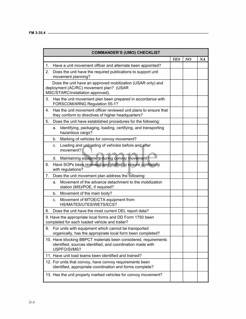
FM 3-35.4 ________________________________________________________________________________
D-4
COMMANDER’S (UMO) CHECKLIST
YES NO NA 1. Have a unit movement officer and alternate been appointed? 2. Does the unit have the required publications to support unit
movement planning?
Does the unit have an approved mobilization (USAR only) and deployment (AC/RC) movement plan? (USAR MSC/STARC/installation approved).
3. Has the unit movement plan been prepared in accordance with FORSCOM/ARNG Regulation 55-1?
4. Has the unit movement officer reviewed unit plans to ensure that they conform to directives of higher headquarters?
5. Does the unit have established procedures for the following: a. Identifying, packaging, loading, certifying, and transporting
hazardous cargo?
b. Marking of vehicles for convoy movement? c. Loading and unloading of vehicles before and after
movement?
d. Maintaining equipment during convoy movement? 6. Have SOPs been reviewed and staffed to ensure conformity
with regulations?
7. Does the unit movement plan address the following: a. Movement of the advance detachment to the mobilization
station (MS)/POE, if required?
b. Movement of the main body? c. Movement of MTOE/CTA equipment from
HS/MATES/UTES/WETS/ECS?
8. Does the unit have the most current OEL report data? 9. Have the appropriate local forms and DD Form 1750 been completed for each loaded vehicle and trailer?
9. For units with equipment which cannot be transported organically, has the appropriate local form been completed?
10. Have blocking BBPCT materials been considered, requirements identified, sources identified, and coordination made with USPFO/SI/MS?
11. Have unit load teams been identified and trained? 12. For units that convoy, have convoy requirements been
identified, appropriate coordination and forms complete?
13. Has the unit properly marked vehicles for convoy movement?
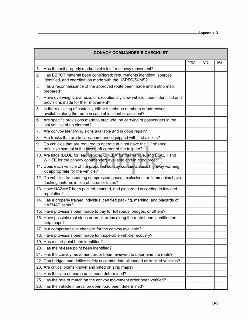
_______________________________________________________________________________ Appendix D
D-5
CONVOY COMMANDER’S CHECKLIST
YES NO NA 1. Has the unit properly marked vehicles for convoy movement? 2. Has BBPCT material been considered; requirements identified, sources
identified, and coordination made with the USPFO/SI/MS?
3. Has a reconnaissance of the approved route been made and a strip map prepared?
4. Have overweight, oversize, or exceptionally slow vehicles been identified and provisions made for their movement?
5. Is there a listing of contacts, either telephone numbers or addresses, available along the route in case of incident or accident?
6. Are specific provisions made to preclude the carrying of passengers in the last vehicle of an element?
7. Are convoy identifying signs available and in good repair? 8. Are trucks that are to carry personnel equipped with first aid kits? 9. Do vehicles that are required to operate at night have the "L" shaped
reflective symbol in the lower left corner of the tailgate?
10. Are flags (BLUE for lead vehicle, GREEN for trail vehicle, and BLACK and WHITE for the convoy commander) available and in good order?
11. Does each vehicle of the proposed convoy contain a basic highway warning kit appropriate for the vehicle?
12. Do vehicles transporting compressed gases, explosives, or flammables have flashing lanterns in lieu of flares or fuses?
13. Have HAZMAT been packed, marked, and placarded according to law and regulation?
14. Has a properly trained individual certified packing, marking, and placards of HAZMAT items?
15. Have provisions been made to pay for toll roads, bridges, or others? 16. Have possible rest stops or break areas along the route been identified on
strip maps?
17. Is a comprehensive checklist for the convoy available? 18. Have provisions been made for inoperable vehicle recovery? 19. Has a start point been identified? 20. Has the release point been identified? 21. Has the convoy movement order been reviewed to determine the route? 22. Can bridges and defiles safely accommodate all loaded or tracked vehicles? 23. Are critical points known and listed on strip maps? 24. Has the size of march units been determined? 25. Has the rate of march on the convoy movement order been verified? 26. Has the vehicle interval on open road been determined?
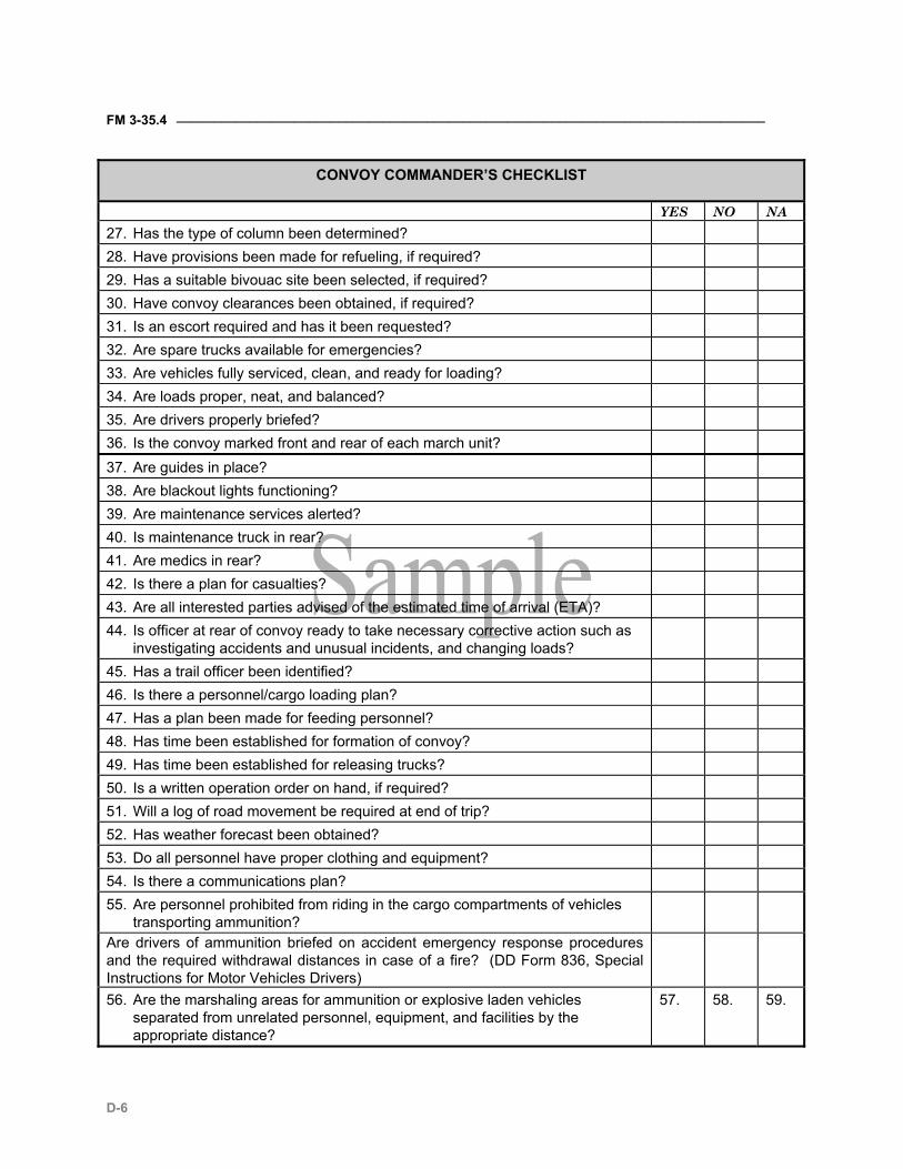
FM 3-35.4 ________________________________________________________________________________
D-6
CONVOY COMMANDER’S CHECKLIST
YES NO NA 27. Has the type of column been determined? 28. Have provisions been made for refueling, if required? 29. Has a suitable bivouac site been selected, if required? 30. Have convoy clearances been obtained, if required? 31. Is an escort required and has it been requested? 32. Are spare trucks available for emergencies? 33. Are vehicles fully serviced, clean, and ready for loading? 34. Are loads proper, neat, and balanced? 35. Are drivers properly briefed? 36. Is the convoy marked front and rear of each march unit? 37. Are guides in place? 38. Are blackout lights functioning? 39. Are maintenance services alerted? 40. Is maintenance truck in rear? 41. Are medics in rear? 42. Is there a plan for casualties? 43. Are all interested parties advised of the estimated time of arrival (ETA)? 44. Is officer at rear of convoy ready to take necessary corrective action such as
investigating accidents and unusual incidents, and changing loads?
45. Has a trail officer been identified? 46. Is there a personnel/cargo loading plan? 47. Has a plan been made for feeding personnel? 48. Has time been established for formation of convoy? 49. Has time been established for releasing trucks? 50. Is a written operation order on hand, if required? 51. Will a log of road movement be required at end of trip? 52. Has weather forecast been obtained? 53. Do all personnel have proper clothing and equipment? 54. Is there a communications plan? 55. Are personnel prohibited from riding in the cargo compartments of vehicles
transporting ammunition?
Are drivers of ammunition briefed on accident emergency response procedures and the required withdrawal distances in case of a fire? (DD Form 836, Special Instructions for Motor Vehicles Drivers)
56. Are the marshaling areas for ammunition or explosive laden vehicles separated from unrelated personnel, equipment, and facilities by the appropriate distance?
57. 58. 59.
_______________________________________________________________________________ Appendix D
D-7
LOGISTICS PLANNING CHECKLIST Yes No NA Supply Unit Supply Operations 1. Is the unit prepared to deploy with current publications, plans, SOPs, or
pre-positioned documents?
2. Are required unit supply regulations/ publications on hand current? 3. Are maintenance/technical manuals for unit equipment on hand current? 4. Does unit have sufficient, up-to-date publications to execute its supply
operations in support of deployment and sustainment operations?
Ammunition Requirements 1. Is the ammunition basic load (ABL) listing current and available? 2. Is the ammunition basic load listing updated and signed by the
commander (required annually and after MTOE change)?
3. Are pre-positioned DA Forms 581 for requesting ammunition at the supporting installation?
4. Are procedures for distribution of TAT ammunition and non-TAT ammunition covered in the unit SOP?
5. Does the unit have a designated supporting ammunition supply point (ASP) for issue of pre-positioned stocks?
6. Does the unit SOP contain a by-bunker breakout of the ammunition basic load (ABL)?
7. Are blocking and bracing requirements for packing ammunition for surface shipment identified and pre-positioned requests provided to the DEH?
8. Are blocking, bracing, and tie-down materials included in the OEL?
Basic, Prescribed and Operating Loads or Classes I, II, III, IV, and IX Requirements
1. Are computed stockage levels adequate to support the unit? 2. Are computation lists for unit basic loads (UBLs) on hand and current? 3. Has the unit included provisions for classes of supply in the OEL? 4. Have significant shortages been identified to higher headquarters and
supply support activities for fill upon deployment?
5. Are on-hand UBLs serviceable/deployable? 6. If required by the OPLAN, are the unit commander and supply personnel
aware of requirements, availability, and necessary quantities of contingency stocks and equipment?
7. Are they aware of points of storage and pickup for these stocks? 8. Is the completed supply request for rations to be consumed en route on
hand and current?
FM 3-35.4 ________________________________________________________________________________
D-8
LOGISTICS PLANNING CHECKLIST Yes No NA 9. Does the unit have a plan (which is not dependent on meal, ready-to-eat
(MREs)) for feeding soldiers until deployment?
10. Has the unit correctly closed out their dining facility and provided alternate meal facilities for their soldiers?
11. Does the unit SOP, or other standing guidance, include procedures for: a. Organization and training of specialized teams such as load teams,
interim property book officer for rear detachment, and others?
b. Delineation of deployment preparation responsibilities for unit members, for example, designation of person responsible for load planning supply requirements?
c. Submission of pre-positioned supply requests (packing and crating materials; Class I, V, VII contingency items)?
d. Reporting MTOE and CTA equipment shortages to higher headquarters for assistance in obtaining needed equipment?
e. Reporting equipment requiring maintenance assistance to deploy? CTA 50-900 1. Are A and B bags packed according to the SOP? 2. Does each soldier have required CTA 50-900 items? Are items in
serviceable condition?
3. Has the unit taken the necessary steps to see that soldiers have an opportunity to draw central issue facility (CIF) items in serviceable condition?
4. Does unit have list of required zone clothing for possible contingencies? 5. Does unit have list of sizes for all personnel?
Disposition of POVs, Privately Owned Weapons, and Pets 1. Does each company/battery-sized unit or detachment have an officer or
NCO appointed as POV receiver for their unit?
2. Are POVs requiring storage identified? 3. Are installation forms being used for POV storage? 4. Is POV turn-in included in the N-hour sequence or deployment SOP? 5. Are pilferable items removed before processing for storage? 6. Are privately owned weapons registered with the provost marshal? 7. Do soldiers and/or the unit have plans for disposition of pets?
NBC 1. Does the unit have a written plan showing distribution of nuclear,
biological, and chemical (NBC) equipment down to the soldier level?
2. Is the NBC hand receipt accurate in terms of authorized MTOE and CTA items?
3. Does unit have on hand the required chemical decontamination
_______________________________________________________________________________ Appendix D
D-9
LOGISTICS PLANNING CHECKLIST Yes No NA
equipment (CDE)? 4. Are there any valid document numbers for CDE shortages on requisition? 5. Does the unit have a list of battle dress uniform (BDU), overshoes, and
gloves requirements by size?
6. Does the unit have DA Form 2765-1 prepared and pre-positioned for the CDE contingency items?
7. Does the unit have anyone on the signature card to pick up the Nerve Agent Antidote Kit (NAAK) and Nerve Agent Pyridostigmine Pretreatment (NAPP)?
8. Does the unit have a packing and loading plan for CDE? 9. Does the unit have a resupply and distribution plan for CDE? 10. (When directed for exercise or operation) Does the unit draw and/or load
the proper amount of CDE?
11. Does every soldier have a properly fitted and serviceable protective mask?
12. Are the authorized quantities of MTOE and CTA items of NBC equipment on hand?
13. Is NBC equipment serviceable? 14. If equipment is not serviceable, does the unit have a viable plan to
replace unserviceable equipment?
15. Does the unit maintain records and track individuals who require optical inserts?
16. Are all pieces of CDE requiring calibration within prescribed timelines? 17. Does the unit maintain proper packaging and shipping placards for CDE,
which contain radioactive sources?
18. Does the unit maintain a record of lot numbers and expiration dates for CDE?
19. Does the unit have a written plan on how they will draw, obtain, and ship decontaminating solution #2 (DS2), supertropical bleach (STB), or other decontaminating agents?
FM 3-35.4 ________________________________________________________________________________
D-10
Annex 2
Deployment Documentation Requirements
VEHICLES(1) CONTAINERS PALLETS, CRATES, CONEXES
PERSONAL BAGGAGE
ALL MODES Warning Placards (when applicable) (for hazardous cargo) X X X
Signature and Tally Record (DD Form 1907) (when applicable) for sensitive cargo accountability
X X X
Unit Identification Code (UIC) and Shipment Unit Number (Stenciled) X(4) X(5) X
Military Shipping Label (DD Form 1387) X(3) X(3) X(3) Packing Lists (DD Form 1750/DA Form 5748-R) X X X
*Security Seal X(2) X ALL MODES, REDEPLOYMENT ONLY *Military Customs Inspection Label (DD Form 1253) or Tag (DD Form 1253-1) X X X X
*U.S. Customs Accompanied Baggage Declaration X
+*Decontamination Tag (DD Form 2271) X X
+Commander’s Certificate (No ammunition or body parts) X X
+Certificate of Registration (CF 4455 or 4457) (when applicable) X
+Registration of War Trophy Firearms (DD Form 603) (when applicable) X X
AIR ONLY Passenger Manifest (DD Form 2131) X Cargo Manifest (DD Form 2130 Series) X X X Pallet Identifier (DD Form 2775) or compatible form X
Special Handling Data/Certification (DD Form 1387-2) (for sensitive and classified)
X X X
Shipper’s Declaration for Dangerous Goods form Miscellaneous (MISC) Pub. 55-3 for hazardous, sensitive, and
X X X
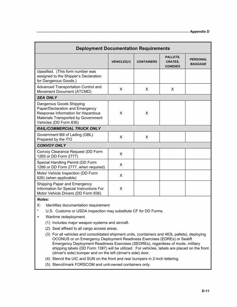
_______________________________________________________________________________ Appendix D
D-11
Deployment Documentation Requirements
VEHICLES(1) CONTAINERS PALLETS, CRATES, CONEXES
PERSONAL BAGGAGE
classified. (This form number was assigned to the Shipper’s Declaration for Dangerous Goods.) Advanced Transportation Control and Movement Document (ATCMD) X X X
SEA ONLY Dangerous Goods Shipping Paper/Declaration and Emergency Response Information for Hazardous Materials Transported by Government Vehicles (DD Form 836)
X X
RAIL/COMMERCIAL TRUCK ONLY Government Bill of Lading (GBL) Prepared by the ITO X X
CONVOY ONLY Convoy Clearance Request (DD Form 1265 or DD Form 2777) X
Special Handling Permit (DD Form 1266 or DD Form 2777, when required) X
Motor Vehicle Inspection (DD Form 626) (when applicable) X
Shipping Paper and Emergency Information for Special Instructions For Motor Vehicle Drivers (DD Form 836)
X
Notes: X: Identifies documentation requirement * U.S. Customs or USDA inspection may substitute CF for DD Forms. + Wartime redeployment.
(1) Includes major weapon systems and aircraft. (2) Seal affixed to all cargo access areas. (3) For all vehicles and consolidated shipment units, (containers and 463L pallets), deploying
OCONUS or on Emergency Deployment Readiness Exercises (EDREs) or Sealift Emergency Deployment Readiness Exercises (SEDREs), regardless of mode, military shipping labels (DD Form 1387) will be utilized. For vehicles, labels are placed on the front (driver's side) bumper and on the left (driver's side) door.
(4) Stencil the UIC and SUN on the front and rear bumpers in 2-inch lettering. (5) Stencil/mark FORSCOM and unit-owned containers only.
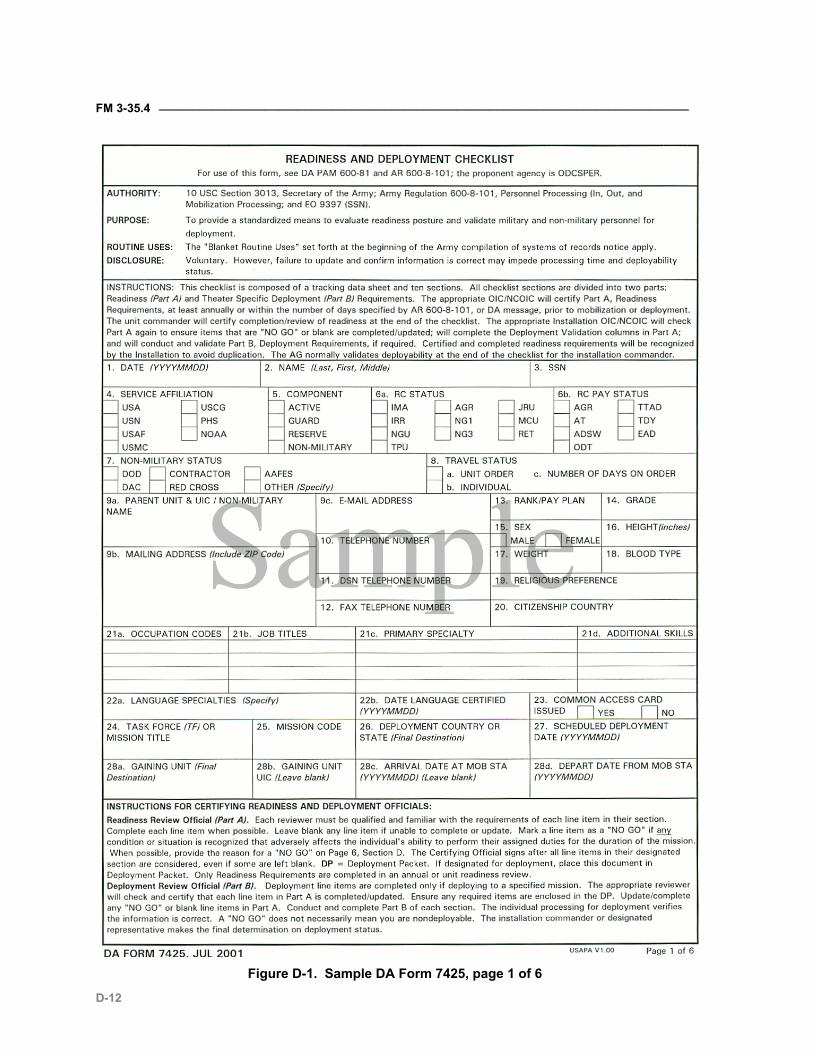
FM 3-35.4 ________________________________________________________________________________
D-12
Figure D-1. Sample DA Form 7425, page 1 of 6
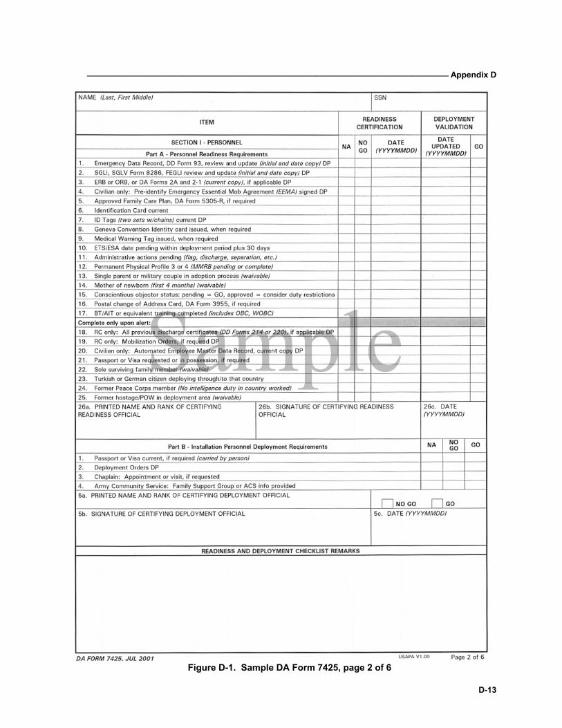
_______________________________________________________________________________ Appendix D
D-13
Figure D-1. Sample DA Form 7425, page 2 of 6
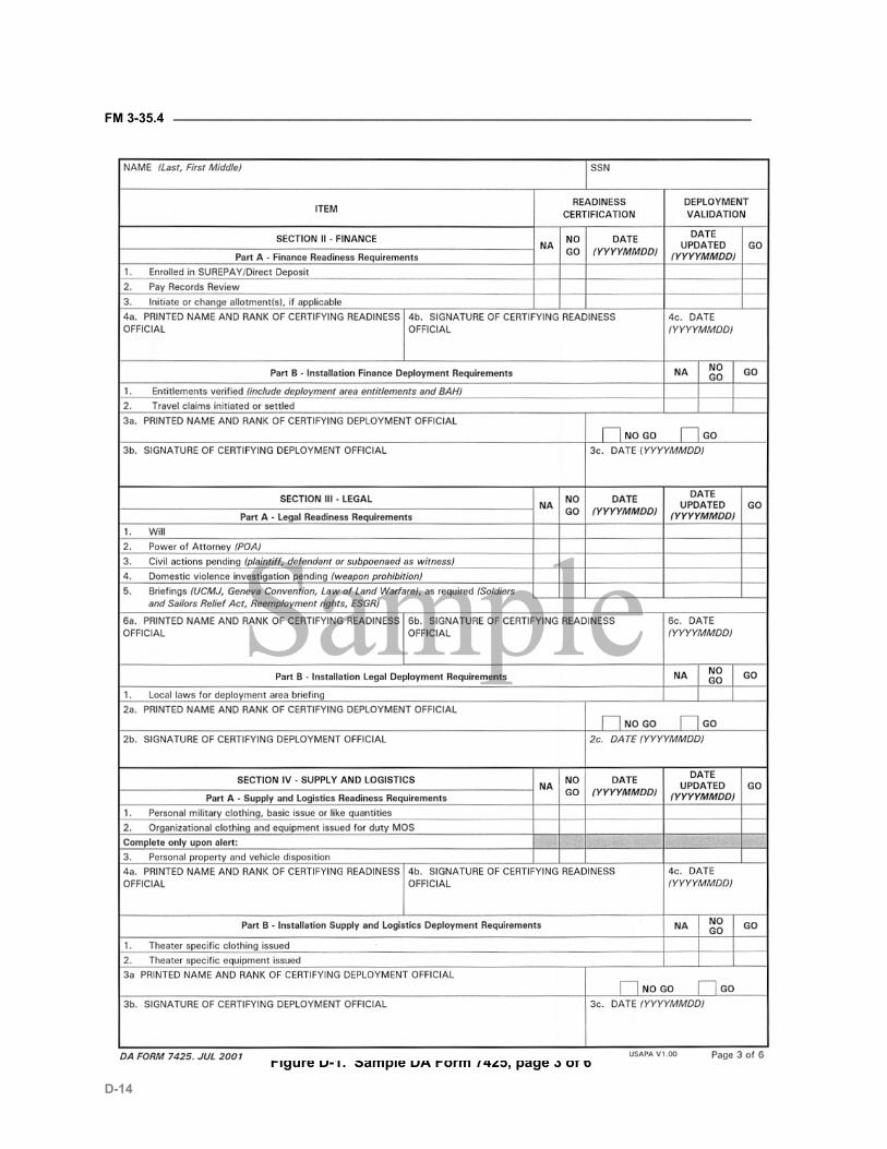
FM 3-35.4 ________________________________________________________________________________
D-14
Figure D-1. Sample DA Form 7425, page 3 of 6
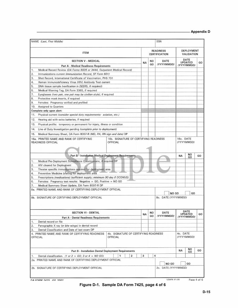
_______________________________________________________________________________ Appendix D
D-15
Figure D-1. Sample DA Form 7425, page 4 of 6
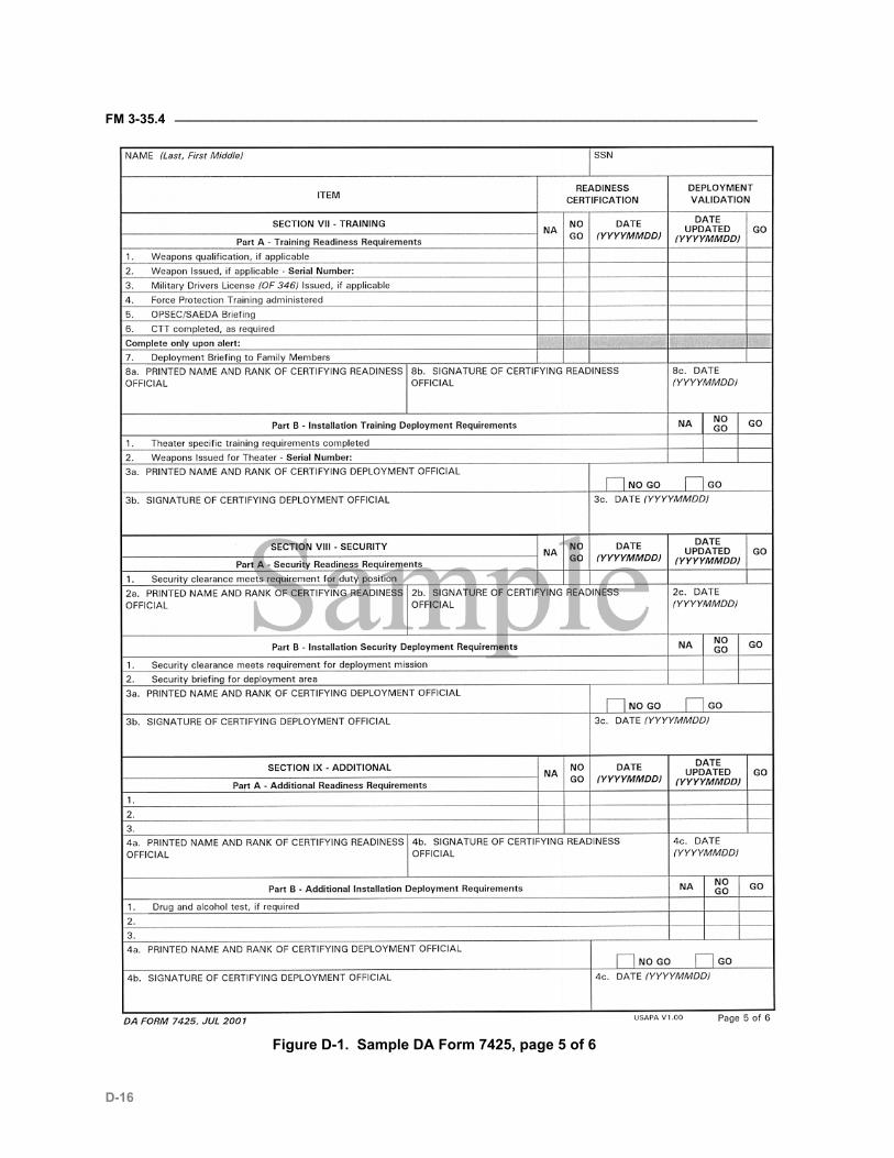
FM 3-35.4 ________________________________________________________________________________
D-16
Figure D-1. Sample DA Form 7425, page 5 of 6
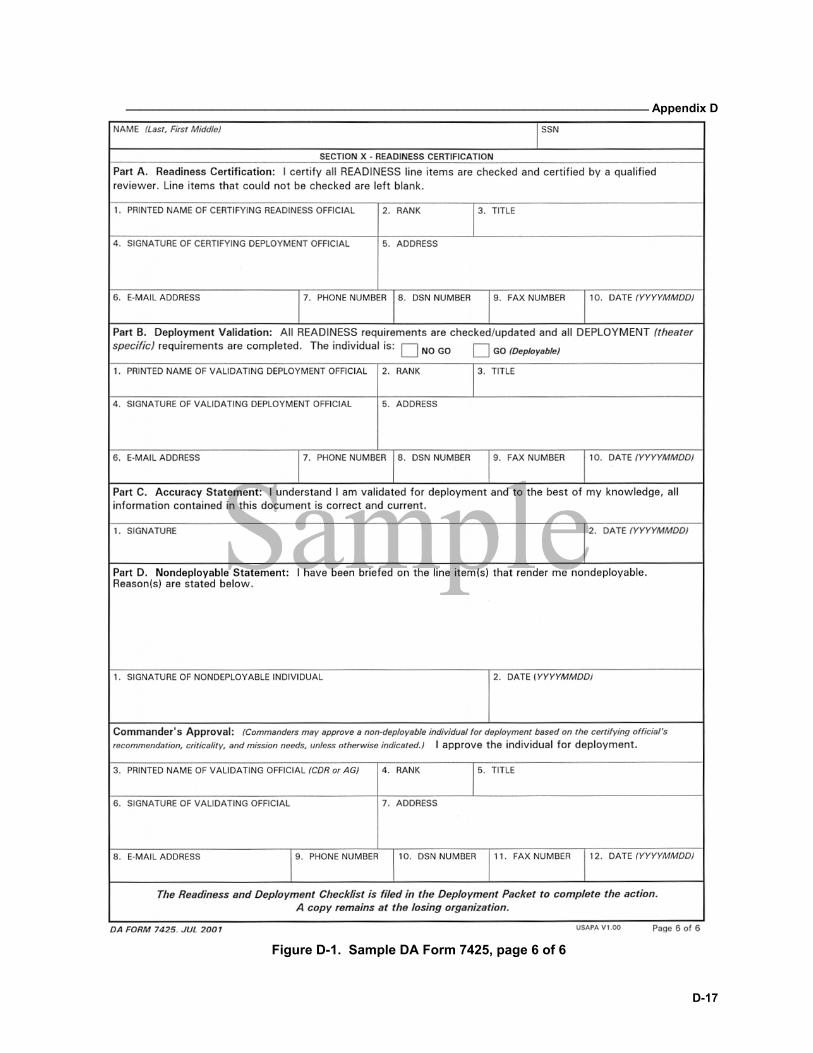
_______________________________________________________________________________ Appendix D
D-17
Figure D-1. Sample DA Form 7425, page 6 of 6
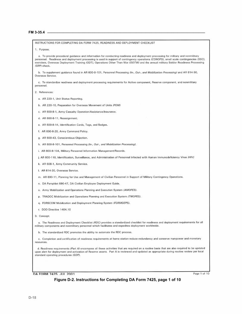
FM 3-35.4 ________________________________________________________________________________
D-18
Figure D-2. Instructions for Completing DA Form 7425, page 1 of 10
_______________________________________________________________________________ Appendix D
D-19
Figure D-2. Instructions for Completing DA Form 7425, page 2 of 10
FM 3-35.4 ________________________________________________________________________________
D-20
Figure D-2. Instructions for Completing DA Form 7425, page 3 of 10
_______________________________________________________________________________ Appendix D
D-21
Figure D-2. Instructions for Completing DA Form 7425, page 4 of 10
FM 3-35.4 ________________________________________________________________________________
D-22
Figure D-2. Instructions for Completing DA Form 7425, page 5 of 10
_______________________________________________________________________________ Appendix D
D-23
`Figure D-2. Instructions for Completing DA Form 7425, page 6 of 10
FM 3-35.4 ________________________________________________________________________________
D-24
Figure D-2. Instructions for Completing DA Form 7425, page 7 of 10
_______________________________________________________________________________ Appendix D
D-25
Figure D-2. Instructions for Completing DA Form 7425, page 8 of 10
FM 3-35.4 ________________________________________________________________________________
D-26
Figure D-2. Instructions for Completing DA Form 7425, page 9 of 10
_______________________________________________________________________________ Appendix D
D-27
Figure D-2. Instructions for Completing DA Form 7425, page 10 of 10
FM 3-35.4 ________________________________________________________________________________
D-28
Annex 3 Blocking, Bracing, Packing, Crating and Tie-down Materials
This annex describes the policy for obtaining and stocking blocking, brac-ing, packing, crating and tie-down (BBPCT) materials and related railcar loading equipment for all mobilizing and deploying units. "BBPCT in Support of Full Mobilization" is the official, all-encompassing title for the program. It includes all materials required to protect vehicles, equipment, and other cargo from damage or loss during transit. Blocking and bracing material (BBM) includes tie-down materials and is the term applied to materials required for rail and truck movement but does not normally in-clude packing and crating materials. It may also be referred to as "BBT" (blocking, bracing, and tie-down) material.
STOCKAGE D-3-1. Installations/activities centrally stock BBPCT material only when it is not possible to get from local sources before the unit deployment date. Enough BBPCT should be on hand to support rapid deployment units. (For example, units that will deploy before getting additional BBPCT.) For USAR units, materials required for movement from point of origin to MS is listed in a separate section of the unit’s movement plan and procured by the unit from predetermined commercial sources following receipt of the alert order and de-termination of mode. USAR units identify BBPCT material on hand every year and provide a copy of the inventory to the regional support command (RSC)/ direct reporting unit (DRU) or the U.S. property and fiscal officer (USPFO)/ director of logistics (DOL). The inventory includes the serviceabil-ity of BBPCT. USAR units identify available vendors and include them in the unit’s mobilization plan.
D-3-2. ARNG units receive assistance from the USPFO and STARC, for equipment moves during mobilization from point of origin to MS. USAR units identify BBPCT material requirements unobtainable at point of origin to the RSC/DRU, STARC, and if assistance in sourcing is required, to the SI.
UNIT MOVEMENT PLANS D-3-3. Unit movement plans contain a separate section on BBPCT material requirements. Units determine the amount of pallets, containers, boxes, banding material, crates, and any other material required to protect and unitize the unit equipment and supplies during transit to the AO. Units re-port these requirements to the activity having implementing responsibility. List and record all BBPCT material required for movement on the appropri-ate local form.
BBT MATERIALS DETERMINATION D-3-4. Planners use the current Association of American Railroads (AAR) Loading Rules to calculate BBT material. In the absence of AAR procedures,
_______________________________________________________________________________ Appendix D
D-29
they use MTMC Pam 55-19. TC-AIMS II will assist in calculating BBT mate-rial.
D-3-5. The actual BBT requirement depends on the following: • Size and type of unit to be loaded. • Types of railcars available. • Amounts of rail outloading required for different POEs and OPLANs.
D-3-6. Each installation DOL/ITO, in coordination with UMC, directorate of plans, training, and mobilization (DPTM), DPW, and civilian railroad offi-cials, identifies and programs BBPCT requirements for their individual in-stallations and supported units and activities.
DEPLOYMENT INSTALLATIONS D-3-7. Commanders of deployment installations provide all BBT material to support deployment. Long lead-time items (items with a procurement time more than 14 days) will be stocked in sufficient quantities to supply the first 30 days of deployment.
D-3-8. For movement from the installation/MS, AC/USAR units furnish their total BBPCT material requirements to their MS unit movement coordinator (UMC) on DA Form 4283 (Facilities Engineering Work Request). If the form is unavailable, they submit the request in memorandum format. The unit annotates the deployment C-Day on the request.
D-3-9. The UMC reviews the material list against the DD Form 1726 (CONUS Military Installation Material Outloading and Receiving Capability Report) to determine if the unit’s out-load deployment data is within the limitations/capabilities of the installation. When the review is completed, a listing of the required material and the respective time frames are furnished through the DPW or appropriate installation activity to the installation di-rector of contracting (DOC) for local purchase review.
D-3-10. The installation DOC performs a local market survey to determine which required items of BBT are readily available in the required quantities from commercial sources. (Those items are not purchased and stocked unless a subsequent market survey shows that the items cannot be acquired prior to the unit out-load date.) The installation conducts the local market survey at least annually due to the changeable nature of supply and demand in the commercial marketplace.
D-3-11. The DOC annotates the materials list, indicating which items are not readily available on the local market. The DOC also maintains the list of readily available materials in a form and manner that expedites acquisition upon deployment. The DOC only gets materials specified by the installation UMC. (That is, the items not readily available and not on hand.)
D-3-12. The DPW/DOL ensures that supply and accountability procedures in-clude control, storage, issue, turn-in, maintenance, and replacement of BBPCT materials, railcar spanners, hand tool sets, portable end ramps, and any other related rail loading equipment.
FM 3-35.4 ________________________________________________________________________________
D-30
D-3-13. The DPW or DOL conducts an annual inventory of BBT material and furnishes it to the installation UMC for review to determine adequacy. Addi-tions or deletions to requirements are annotated on the listing and processed through the installation DOC as necessary for inventory adjustment. The annual inventory indicates the condition of the BBT and whether it is a can-didate for rotation. The material is stocked separately from the stock fund inventory as mobilization stockage. Due to shelf life consideration, materials are rotated from the BBPCT inventory.
D-3-14. BBT is stripped from the equipment at the APOE/SPOE. The MTMC port commander has first priority for using BBPCT removed at the SPOE. Available transportation is used to return residual material to the respective installations for possible reuse.
RAIL LOADING EQUIPMENT D-3-15. Rail loading equipment includes (but may not be limited to) hand tool sets, railcar spanners (or bridge plates), and portable end loading ramps (sin-gle and multilevel).
HAND TOOL SETS D-3-16. The DOL manages the inventory of BBPCT hand tool sets needed for installing BBPCT material during mobilization. BBPCT hand tool sets may be used for normal (non-mobilization/deployment) shipping activities. Instal-lations ensure that accountability, control, maintenance, storage, and re-placement procedures are clearly established to ensure sufficient hand tool sets are on hand in case of mobilization/deployment shipping activities. To calculate the number of hand tool sets required, divide by four the number of rail flatcars that are expected to be positioned for a single loadout. Add five percent for breakage and round to the nearest whole number. (If .4 or lower, round down; if .5 or higher, round up. Example: 78 railcars divided by 4 = 19.5 x 1.05 = 20.475 tool sets, which rounds to 20.)
RAILCAR SPANNERS D-3-17. Railcar spanners (bridge plates) may be used for normal peacetime shipping activities. However, accountability controls, maintenance, storage, and replacement procedures must be clearly established to ensure sufficient spanners are on hand in case of mobilization. To calculate the number of spanners required, figure one set (two spanners) for each rail flatcar expected to be positioned for a single loadout. Add an additional set for each perma-nent end ramp to be used for loading. Then add five percent for breakage and round as in the above paragraph. (Example: 78 railcars loading at three permanent end ramps: 78 + 3 = 81 x 1.05 = 85.05, which rounds to 85 sets of spanners.)
PORTABLE END LOADING RAMPS D-3-18. Portable end loading ramps may be single level (for standard flat-cars) or adjustable multilevel (for loading bi-level railcars). They may be ei-ther towed or self-propelled and are normally procured and managed as TDA items. Like spanners, the ramps may be used for normal operational activi-
_______________________________________________________________________________ Appendix D
D-31
ties provided they are properly controlled and maintained or replaced if nec-essary to ensure availability for mobilization. There is no formula to deter-mine the number and types of portable ramps required. This can only be de-termined by the ITO’s careful evaluation of the magnitude of the outload mis-sion, compared to the physical facilities (permanent loading ramps/docks) available. The DOL should initiate action to add to the installation TDA the number and type of ramps required but not currently authorized.

E-1
Appendix E
Unit Movement Plan (Sample)
This annex provides ideas, data, and samples of many items that must be considered in developing the unit movement plan. USAR units complete one plan from point of origin to MS, and, if required, one from MS to POEs. AC units prepare movement plans for deployment to the POEs. The plan is written in operation order format according to FM 5-0 (101-5). It becomes an order when adding required data and specific times. A unit may have several plans, each one planning for a specific contingency. The unit plans the move using the movement plan and executes the move un-der an operation order. The movement plan contains all annexes and ap-pendices. Those not used are marked “NA” so that later developing plan-ning data may be added to the existing plan. The operation order has spe-cific movement instructions and is dated and signed. The annexes contain information required to support the plan.
FM 3-35.4 ________________________________________________________________________________
E-2
UNCLASSIFIED
Classification Copy no__of__copies
(Issuing Unit) (Street Address)
(City, State, ZIP Code) (Date of Plan)
MOBILIZATION MOVEMENT PLAN (Point of Origin to MS) (USAR Only)
DEPLOYMENT MOVEMENT PLAN (MS to A/SPOE) (AC) (USAR, if required)
References: FM 4-01.40 (55-30), STARC, RSC, Direct Reporting Unit (DRU), and Installation
Mobilization/Deployment Plan, (Any other maps, SOPs, manuals, etc.)____include dates of publica-tions
Time Zone used Throughout the Plan: _____
Task Organization HQ, HHC,___Bn_____,___ Co A _______,__ Co B _______,__ Co C _______,__ Co D _______,__ ____Det_____,__
1. SITUATION: This should be a generalization of when/how the plan is to be implemented.
a. Attachments and Detachments: Listed with appropriate units or the word "none."
b. Assumptions: These are conditions a commander believes will exist at the time the plan be-comes a movement order. Assumptions are clearly stated and address— (1) Equipment serviceability. (2) Availability of personnel for movement. (3) MTOE supplies and equipment to be transported. (4) Pre-positioned equipment, if applicable. (5) Vehicles/equipment in maintenance. (6) MS gate assignments/time to MS/APOE/SPOE. (7) Use of modes to MS/APOE/APOE. (8) Commercial movement.
_______________________________________________________________________________ Appendix E
E-3
The following are examples of some assumptions: (1) All unit equipment will be combat serviceable. (2) All unit personnel will be available for movement. (3) During a selected 200K call-up, cross-leveling of personnel and equipment will occur. (4) All (including excess) MTOE/TDA equipment and supplies will be transported to the MS
(USAR only). (5) All vehicles and equipment on job order or hand receipt will be recovered prior to depar-
ture from point of origin or arrangements will be made during Phase II for pick up by the unit or to ship commercially directly to the mobilization station (MS) (USAR only).
(6) MS gate assignments and arrival/departure times have been designated by the MS and coordinated with the DMC.
(7) Organic convoy movements from point of origin to the MS and subsequently to A/SPOE will be administrative.
2. MISSION: A concise statement of what is to be accomplished and its purpose. It accomplishes the following—
a. Identifies unit(s).
b. Identifies origin and destination.
c. Identifies date and time movement begins and ends.
d. Identifies methods of movement: organic/commercial, and mode: truck, rail, air, and sea.
e. Identifies reason for moving (OPLAN, etc.).
An example of a mission statement from a mobilization movement plan is— The (issuing unit)___will move from point of origin to (MS)___to arrive not later than (date/time first element arrives at the gate)___. Advance parties will depart not later than (date/time of earliest ad-vance party departure)___. Commercial transportation consisting of (trucks, buses, and/or rail)___(will/will not)___ be used, but will not necessarily move with the organic convoys. An example of a mission statement from a deployment movement plan is— On order, the (unit name)______will establish staging/marshaling areas and deploy personnel and equipment to perform operations in the designated area of operations. Units will deploy from (installa-tion)_____via APOE______and SPOE. (Transportation motor pool (TMP)/commercial buses) will transport personnel to the APOE. All roadable vehicles will be convoyed to the SPOE. Non-roadable vehicles will go by rail or commercial truck to the SPOE. Movement will commence in accordance with (IAW) the alert order and the N-hour sequence (Annex S). Movement will be by (organic assets to the SPOE, or rail, or commercial truck)____. Order of march will be advance party followed by main body. Unit will be prepared to deploy on other contingency missions.
3. EXECUTION: This paragraph addresses the necessary planning, coordination, and execution functions that must take place in order to accomplish the mission. Specific tasks are given.
a. Concept of Movement: The concept clarifies the purpose of the plan. It addresses (point of origin to MS and MS to A/SPOE)— (1) Receipt of movement orders.
FM 3-35.4 ________________________________________________________________________________
E-4
(2) Update and validation of OEL. (3) Recovery of equipment. (4) Commercial movement of personnel (by buses, and other modes). (5) Deadline to complete packing and loading. (6) Advance party composition. (7) Main body composition. (8) Order of march and convoy numbers for highway movement. (9) Shuttle of equipment (USAR only must obtain permission from the MS). (10) Commercial movement of vehicles/equipment. (11) Priority of support. (12) MO/ITO coordination. (13) ITO designated load dates and locations. (14) UMO duties and responsibilities. (15) Projected POEs. (16) Applicable OPLAN. (17) Actions at POE (reduction, receipt of cargo, and others).
Examples of Concept of Movement statements are— (1) Upon receipt of the alert notification, the first priority will be for the UMO to review the Re-
quest for Commercial Transportation and OEL. (2) To meet MS gate arrival/departure times, the unit will conduct simultaneous coordination,
processing, and loading operations using the unit’s N-hour sequence (Annex S). (3) Start point times are IAW DD Form 1265 (Request for Convoy Clearance) (Annex __). (4) Commercial transportation/support requirements are located at Annex ___. (5) All organic vehicles will have a driver and assistant driver. (6) The UMO will coordinate and confirm— (a) Changes to DD Form 1265. (b) Request for commercial transportation with transportation office NLT___. (c) En route stops/halts with appropriate businesses. (7) Commercial buses will be used to transport personnel and baggage. A troop commander
will be designated for each commercial bus. (8) Supplies and equipment will be packed, cushioned, and/or crated, and loaded on organic
vehicles IAW current vehicle load cards no later than (number of hours)____prior to depar-ture.
(9) Advance party elements will be composed of personnel, equipment, and documentation required to accomplish tasks identified by the MS and will move by organic convoy IAW Annex ___. Vehicles will infiltrate to (consolidation point)____ where battalion advance party convoy will form. The convoy number will be ___.
(10) Main body organic convoys will depart point of origin/MS IAW Annex ___. Individual con-voys will consolidate at (consolidation point)____.
(11) Order of march and convoy numbers will be— Unit___ Convoy Number ___
_______________________________________________________________________________ Appendix E
E-5
Unit___ Convoy Number ___ Unit___ Convoy Number ___ Unit___ Convoy Number ___ Unit___ Convoy Number ___ Unit___ Convoy Number ___ Unit___ Convoy Number ___ (12) Shuttle convoys (will/will not) be used. (13) Unit supplies and equipment will be prepared for commercial movement by (rail, truck,
etc.)___ IAW the OEL in the unit load plan not later than (date/time)___.
b. Tasks to Subordinate Units/Elements: This paragraph clarifies and states tasks and timelines in sufficient detail to ensure action by subordinates or platoons/sections within a company. It addresses the following as relates to the actual move: (1) Company, platoon, or section tasks. (2) Maintenance. (3) Supply. (4) Food service. (5) Rear detachment. (6) NBC. (7) Loading teams. (8) Training. (9) Rail guards, convoy guides, supercargoes, etc. Reports.
Examples of tasks listed in this section are— (1) Company, battery, or detachment advance party vehicles will convoy to consolidation point
at___(date/time). (2) Maintenance: date/time to stop repairs and load maintenance equipment. (3) Supply: date/time to complete issue and start loading. (4) Food service: date/time to close down food service operation, clean up, and load food ser-
vice section equipment. (5) NBC: CDE guidance--disposition of CDE, load on vehicle or issue to individual. (6) Load teams: date/time to complete loading of advance party, main body, commercial loads,
and others.
c. Coordinating Instructions: These list requires coordination for planning and executing phases with— (1) Higher headquarters. (2) STARC/MUSARC/next higher headquarters. (3) Mobilization station/ITO.
FM 3-35.4 ________________________________________________________________________________
E-6
(4) Mobilization and training equipment site (MATES) and equipment concentration site (USAR Only).
(5) Transportation terminal nodes (bus terminal, railhead, APOE, SPOE, MAs, STARC movement control center (MCC) for highway movements).
(6) Local agencies and businesses. (7) All elements internal to unit.
Example of coordination covered in this paragraph is— Physical security officer will coordinate current information with local and state police NLT _______ days prior to movement.
4. SERVICE SUPPORT: This paragraph lists the support needed for the unit move. They must be listed either in the basic plan or as annexes to the plan. As a guide, if the information for a sub-paragraph will fit on one page, include it in the body of the plan. This makes your plan easier to read and easier to use. If the information for a subparagraph is longer than one page, consider placing it in an annex.
The following should be addressed—
a. Supply— (1) Class I (See Annex__). This annex/subparagraph should address subsistence for—
(a) Advance party. (b) Main body. (c) MATES/ECS recovery or load teams (if applicable).
(2) Class II (See Annex__). This annex/subparagraph should cover any pertinent informa-tion on organizational clothing and individual equipment (OCIE).
An example of an item in this subparagraph is— Due to movement being an administrative one, all weapons, NBC equipment, and other non-combat OCIE will be packed, boxed, and moved adminis-tratively.
(3) Class III (See Annex__). This annex/subparagraph should address— (a) Topping off vehicles. (b) Trail party requirements. (c) En route refueling. (d) Packaged requirements. (e) Bulk requirements. (f) Motor fuels. (g) Aviation fuels.
Examples of items included in this subparagraph include— (a) All vehicles will be topped off and will carry fuel cans strapped in the mounts. Units without a
fuel-dispensing facility will purchase from a local vendor using SF 44. (b) The trail maintenance party will carry the minimum quantities of packaged POL supplies to
support the convoy as listed below:

_______________________________________________________________________________ Appendix E
E-7
48 qts 15W40 oil 15 gals OE/HDO 30 oil (5-gal cans)
10 gals GO 80W09 oil (5-gal cans) 35 lbs GAA grease (pail) 24 qts Dextron II (trans fluid) 1 gal Brake fluid (1-gal can) 5 gals Cleaning solvent 1 bdl Rags (c) Refueling en route will be by (credit card, 5-gal cans, organic tanker, SF 44, or other).
(4) Class IV (See Annex__). This annex/subparagraph should include BBPCT require-ments and pre-positioned requests, along with construction materials.
Examples of items included in this subparagraph are— (a) All barrier/construction materials will be shipped. (b) The complete BBPCT list for the unit is in Annex __.
(5) Class V (See Annex___). This annex/subparagraph includes guidance on the transpor-tation of ABL.
(6) Class VI (See Annex___). This annex/subparagraph should be included if directed by OPLAN/OPORD.
(7) Class VII (See Annex___). This annex/subparagraph should cover— (a) Retrieval and commercial shipment procedures in MATES/ECS (USAR only). (b) Procedures for loading and accounting for equipment moved by commercial rail or
truck. (c) Civilian ambulances and medical personnel may be used for assistance and
evacuation.
An example of an item included in this subparagraph is: Major end items will be loaded IAW Annex ____. For USAR units, all excess MTOE equipment will be transported to the MS.
(8) Class VIII (See Annex__). This annex/subparagraph should address— (a) On-hand medical supplies transported to the MS/POE. (b) Supplies for en route medical support.
Examples of items included in this subparagraph are— (a) All vehicles/aidmen will move with authorized first aid kits. (b) Medical emergencies en route will be evacuated to the nearest hospital.
(9) Class IX (See Annex__). This annex/subparagraph should address—

FM 3-35.4 ________________________________________________________________________________
E-8
(a) Combat Assigned or Authorized Stockage List (ASL)/PLL drawn from appropriate source and loaded on organic vehicles.
(b) Trail party requirements.
Examples of items to be included in this subparagraph are— (a) Combat PLL will be loaded on organic vehicles. (b) All Class IX ASL/PLL will be packed, crated, and/or boxed to meet requirements of An-
nex__. (c) During the convoy, the trail party will carry, as a minimum, the items identified in Annex__. (d) Excess PLL will be transported to the MS and turned in (USAR only).
(10) Class X (See Annex__). This annex/subparagraph covers material to support nonmili-tary programs such as agriculture and economic development (not authorized for mobi-lization).
b. Maintenance:
(1) Pre-movement support requirements (Annex __). This annex/subparagraph should in-clude information on training, cleaning, and purging fuel containers and on priority of maintenance support.
(2) En route support requirements (Annex __). This annex/subparagraph contains informa-tion on coordination for en route support (supporting facilities and POC names and phone numbers), trail party requirements, and en route PMCS, if required.
Examples of the items contained in this subparagraph are— (a) The trail party for the main body will consist of ____vehicles and ____personnel. (b) En route PMCS will be performed at the halt number ____. (c) If a vehicle fails, stops, or has an accident, only that vehicle will halt. The maintenance trail party will provide assistance and keep the convoy commander informed.
c. Transportation:
(1) Air. (Annex ____, if required)
(2) Convoy. (Annex ____, if required)
(3) Rail. (Annex ____, if required)
(4) Commercial. (Annex ____, if required)
(5) Unit movement data (UMD). (Annex ____)
d. Procurement
e. Facilities/Equipment
f. Medical Evacuation Procedures
g. Personnel:
_______________________________________________________________________________ Appendix E
E-9
Examples of items contained in this paragraph are— (1) Uniform for movement will be battle dress uniforms (BDUs) (combat boots and berets). (2) All personnel accountability inspections and convoy briefings (Annex M) will be conducted
prior to movement (Annex S).
(3) Each individual is authorized a total weight of ___for personal baggage, ___duffle bags for TA-50, and for clothing and comfort items. The unit’s scales will be used to confirm this.
h. Civil/Military Coordination, if required
i. Other:
(1) Points of contact. (Annex ____)
(2) Coordinating instructions.
5. COMMAND AND SIGNAL.
This paragraph addresses—
a. Chain of command, to include convoy commanders, bus troop commanders, and others.
b. Personnel control (formations, briefings, safety, and such).
c. Command locations.
d. Signal instructions (telephone, radio, and such).
(1) Commercial telephone.
(2) Expedited movement reports procedures.
(3) Radio procedures.
(4) Current signal operating instructions.
e. N-Hour sequence (See Annex ____).
The commander or specifically authorized representative must sign the movement plan. If the signa-ture is not reproduced or on subsequent copies, authentication by the appropriate coordinating staff officer is required.
Annexes are used for those items that would require too much space in the basic plan. If an annex is not necessary, or unused, type title and N/A.
FM 3-35.4 ________________________________________________________________________________
E-10
ANNEX A - Procurement. This annex includes sources for specific commodities and services.
ANNEX B - Class I - Subsistence. This annex covers en route meals and gratuitous health and welfare items.
ANNEX C - Class II. This annex covers all guidance on clothing, individual equipment, tentage, organizational tool sets, NBC equipment, hand tools, electronics, administrative housekeeping supplies, and weapons.
ANNEX D - Class III. This annex gives guidance for aircraft and surface vehicles, coolants, de-icing and antifreeze com-pounds (together with components and additives of such products) and coal, hydraulic and com-pressed gases and lubricants.
ANNEX E - Class IV. This includes information on material for securing vehicle secondary loads and securing major end items to transportation assets.
• Appendix 1 - BBPCT material for secondary cargo/loads in vehicles, trailers and containers, dunnage/shoring for air deployment, and plastic pallet covers for 463L pallets.
• Appendix 2 - Required documentation. This includes work order requests or memoranda for BBT. (Requisitions are used to order packing, crating, and plastic covers).
ANNEX F - Class V. Class V includes ammunition of all types (including NBC and special weapons), bombs, explosives, mines, fuses, detonators, pyrotechnics, propellants, and other associated items. This annex should include the time and location of issue. This annex is not available for USAR mobilization movement plans.
ANNEX G - Class VII. Class VII includes final combinations of end products that are ready for their intended use (that is, tanks, launchers, mobile machine shops and vehicles, MHE, compressors, and construction equip-ment). The annex covers procedures for loading and accounting for equipment moved by commercial truck or rail. It also includes the time major end items will be loaded on commercial assets (reference - unit N-Hour sequence). It includes an equipment retrieval plan (USAR only).
ANNEX H - Class VIII. Class VIII is medical material, including medical peculiar repair parts. In addition to Class VIII, this annex covers en route medical support - first aid kits and medical support at SPOEs/APOEs.
ANNEX I - Class IX. This annex covers guidance on repair parts (less medical peculiar repair parts and components), to include kits, assemblies and subassemblies, repairable and non-repairable, required for maintenance support of all equipment.
ANNEX J - Pre-movement Maintenance Support. This annex covers such items as equipment status, contact teams, drivers’ licenses, PMCS, se-quence of events for maintenance operations, non-repairable equipment, tow bars, and topping off vehicles.
ANNEX K - Equipment Maintenance Support. This covers maintenance during the actual move. It discusses abandoned vehicles, roadside repairs, tow bars, contact teams, repair services/parts, and maintenance vehicles.
_______________________________________________________________________________ Appendix E
E-11
ANNEX L - Air Transportation. This annex always covers personnel, TAT, and baggage. It also covers equipment if the OPLAN/OPORD indicates.
• Appendix 1 - Documentation. Documentation includes— DD Form 2130-1, C5 Cargo Manifest DD Form 2130-3, C141 Cargo Manifest DD Form 2130-6, KC10 Cargo Manifest DD Form 2327, Unit Aircraft Utilization Plan
This appendix reflects— -Equipment/TAT/cargo to deploy by air. -Number of personnel and cargo to deploy. -Bulk, oversized, and outsized equipment designated to deploy by air.
• Appendix 2 - Listing of Pintle-Hook Vehicles (if authorized to ship major end items by air; oth-erwise, personnel pallets only will be indicated).
• Appendix 3 - Air Loading Procedures. This may include— TAB A - Planeload commander’s SOP. TAB B - Load team SOP. TAB C - Shoring material requirements. TAB D - 463L pallet and tie-down requirements. TAB E - Motor and aviation fuels for movement of organic air equipment. TAB F - Special handling cargo certification.
ANNEX M - Convoy Requirements. This annex contains information, requirements, and forms.
• Appendix 1 - Request for Convoy Clearance, DD Form 1265 (FM 55-30). • Appendix 2 -Request for Special Hauling Permit, DD Form 1266 (Request for Special Hauling
Permit) (for outsized/overweight equipment). • Appendix 3 - Convoy Commander’s Checklist. • Appendix 4 - Drivers’ Strip Maps. • Appendix 5 - Convoy Commander’s Safety Briefing.
The briefing should be used to ensure— Drivers are licensed for vehicles being driven.
ο Any hazardous material that is part of the load is identified on DD Forms 1750 and 836, and on the OEL.
ο Vehicles are properly prepared for movement. Considerations include— ο Shipping configuration. ο Fuel levels. ο Secured secondary loads. ο Shackles. ο Purging requirements. ο Flags.
FM 3-35.4 ________________________________________________________________________________
E-12
ο Convoy signs. ο Highway warning kits. ο First aid kits. ο Convoy speeds.
ANNEX N - Rail Requirements. This annex includes information, procedures and documentation for rail movement. This annex is in-cluded only for those units where rail movement is projected.
• Appendix 1 - Load Team SOP. • Appendix 2 - Documentation and Procedures for Rail Loading Equipment.
This appendix includes a rail load plan and is used to ensure training is validated and vehi-cles are properly prepared for movement. Guidance on vehicle preparation includes— Shipping configuration. Fuel levels. Secondary loads secured. Shackles. Markings (UIC and shipment unit number (SUN)). MSLs. Purging requirements. First aid kits. Vehicle placards in place if HAZMAT is part of the load.
ANNEX 0 - Commercial Movements Requirements. This annex includes information, procedures and documentation necessary for commercial move-ment.
• Appendix 1 - Packing List (DD Form 1750). See Annex ____. • Appendix 2 - FORSCOM Form 285-1-R.
Note. If distance is less than 400 miles, equipment must be non-roadable.
Distance to travel to SPOE must be more than one day (400 miles) road march.
ANNEX P - Facilities/Equipment. This annex covers facilities en route and equipment requirements for loading/unloading at point of ori-gin/MS.
ANNEX Q - Points of Contact Listing. This annex lists POCs pertinent to the movement.
ANNEX R - Safety. This annex covers—
• Motor vehicle operations. • Rail load operations. • Air load operations. • Accident/injury prevention. • Ammunition and explosive/POL safety.

_______________________________________________________________________________ Appendix E
E-13
• Prevention of carbon monoxide poisoning. • Senior vehicle occupant responsibilities.
ANNEX S - N-Hour Sequence. This annex identifies and schedules movement tasks.
ANNEX T - Plan Coordination Documentation. This annex includes—
• Documentation requiring action from another command or agency, intermediate headquar-ters, and local agencies/businesses.
• OPLAN information - location and procedures.
ANNEX U - Appointment Memorandums and Training Certificates and/or Validations. This annex includes instructions, requirements and documentation for providing certificates or valida-tions during movement.
ANNEX V - Plan Approval. This annex includes the approved plans. Plans will be validated and approved by the chain of com-mand (battalion, brigade, division, and/or installation). The plan(s) will be sent through the chain of command BEFORE submitting to installation UMC/USAR MSC/STARC DMC for final approval.
ANNEX W - Unit Movement Data. It is not necessary to forward this annex for approval unless required by approving authority.
• Appendix 1 - OEL Printout.
This appendix contains the OEL printout and may be cross-matched with equipment listed on the DD Form 1750 and higher headquarters using shipment unit number. OELs will be re-viewed annually by the installation UMC for AC, biannually by the MSC for USAR, and bian-nually by the STARC DMC for ARNG. Vehicle load cards must cross match with AUEL and packing list using SUN sequence.
• Appendix 2 - Packing list (DD Form 1750).
This list for air, rail, convoy, and commercial movement must cross match with OEL and higher headquarters SUN sequence.

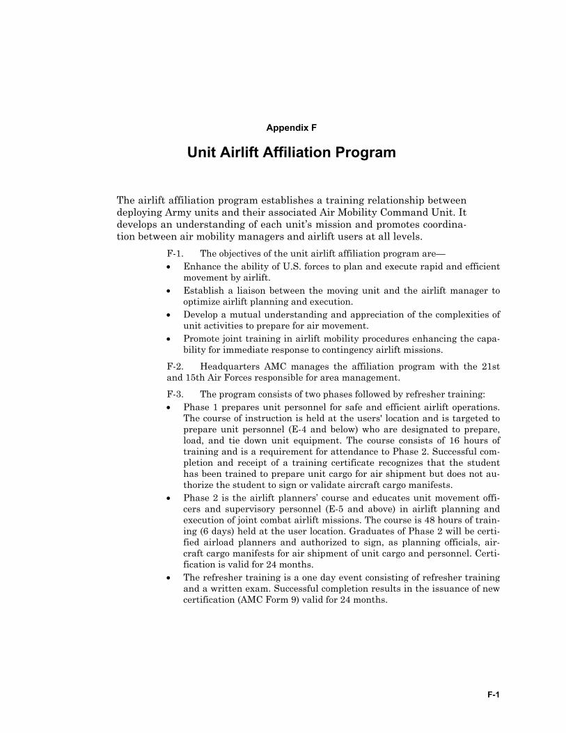
F-1
Appendix F
Unit Airlift Affiliation Program
The airlift affiliation program establishes a training relationship between deploying Army units and their associated Air Mobility Command Unit. It develops an understanding of each unit’s mission and promotes coordina-tion between air mobility managers and airlift users at all levels.
F-1. The objectives of the unit airlift affiliation program are— • Enhance the ability of U.S. forces to plan and execute rapid and efficient
movement by airlift. • Establish a liaison between the moving unit and the airlift manager to
optimize airlift planning and execution. • Develop a mutual understanding and appreciation of the complexities of
unit activities to prepare for air movement. • Promote joint training in airlift mobility procedures enhancing the capa-
bility for immediate response to contingency airlift missions.
F-2. Headquarters AMC manages the affiliation program with the 21st and 15th Air Forces responsible for area management.
F-3. The program consists of two phases followed by refresher training: • Phase 1 prepares unit personnel for safe and efficient airlift operations.
The course of instruction is held at the users' location and is targeted to prepare unit personnel (E-4 and below) who are designated to prepare, load, and tie down unit equipment. The course consists of 16 hours of training and is a requirement for attendance to Phase 2. Successful com-pletion and receipt of a training certificate recognizes that the student has been trained to prepare unit cargo for air shipment but does not au-thorize the student to sign or validate aircraft cargo manifests.
• Phase 2 is the airlift planners’ course and educates unit movement offi-cers and supervisory personnel (E-5 and above) in airlift planning and execution of joint combat airlift missions. The course is 48 hours of train-ing (6 days) held at the user location. Graduates of Phase 2 will be certi-fied airload planners and authorized to sign, as planning officials, air-craft cargo manifests for air shipment of unit cargo and personnel. Certi-fication is valid for 24 months.
• The refresher training is a one day event consisting of refresher training and a written exam. Successful completion results in the issuance of new certification (AMC Form 9) valid for 24 months.

G-1
Appendix G
Hazardous Cargo
All hazardous cargo must be prepared and documented according to ap-propriate regulations. When equipment is packed and loaded, HAZMAT must be identified and properly segregated. All HAZMAT moving by air must be certified in accordance with Air Force Joint Manual (AFJM) 24-204/TM 38-250/Naval Supplement (NAVSUP) Publication 505/Marine Corps Operations Pamphlet (MCOP) 4030.19F/Defense Logistics Agency Manual (DLAM) 4145.3. Units follow the steps outlined below for surface shipments.
DOCUMENTING HAZARDOUS CARGO MATERIAL FOR SURFACE SHIPMENT
G-1. The following steps may be used as a guide when shipping HAZMAT. Use this guide with 49 CFR, Parts 100-177. If the shipment is going interna-tional, see the Intermodal Maritime Dangerous Goods Code (IMDGC). The planner should— • Determine the proper shipping name and number. The shipper must se-
lect the proper shipping name of the materials as listed in the Hazardous Materials Table.
• Determine the hazard class or classes. Materials are classed by the proper name in the Hazardous Materials Table. (Hazard class definitions are located in 49 CFR.) If the materials have more than one hazard class, classify the materials by hazard precedence.
• Determine the modes of transport to the destination area. The shipper must ensure that the shipment complies with the various modal re-quirements. Mode of transport affects the packaging, quantity per pack-age, labeling and segregation of HAZMAT.
• Select the proper labels and apply as required. Refer to the proper section of the Hazardous Materials Table.
• Determine and select the proper packaging
Notes. Most countries enforce the International Maritime Dangerous Goods Code for import surface shipments of HAZMAT. Department of Transportation (DOT) regulations require HAZMAT classification and labeling according to 49 CFR and the IMGDC.
Labels are not required for fuel in vehicle tanks.
FM 3-35.4 ________________________________________________________________________________
G-2
• Mark the packaging. Apply the required markings, proper shipping name, identification number, as required, and the TCN or UIC/shipment unit number.
• List HAZMAT packed inside containers or vehicles first (refer to steps 1 through 3).
Note. HAZMAT permits only authorized abbreviations. Refer to 49 CFR.
• Determine the proper placards. Refer to 49 CFR. • Determine segregation requirements for HAZMAT. Rail, ocean vessel,
highway, or a combination of these modes may ship HAZMAT. If two or more modes transport the cargo, segregation standards for each mode must be met.
• Prepare appropriate shipping papers. • Ensure water commodity and special handling codes are used on the
OEL/UDL. • Ensure compliance with the DOT emergency response guidebook (DOT P
5800.5).
PREPARING SHIPMENT UNITS OF HAZARDOUUS MATERIAL FOR SHIPMENT
G-2. Rules governing segregation requirements for hazardous cargo must be met. When in doubt about shipping any hazardous or questionable mate-rials, units separate them from the rest of the unit cargo. If they cannot iden-tify the hazard class or classes, they consult the installation safety office or the ITO. The deploying unit ensures— • Loose ammunition and explosives are removed from all containers and
vehicles. Ammunition is not permitted into the port or aboard vessels without prior authorization from MTMC.
• Vehicle fuel tanks are only three-quarters full. (See DOT Exception 7280.) (Hazardous placards are not required for fuel in vehicle tanks.)
• Fire extinguishers remain aboard motor vehicles and secured in brackets. • Oxygen and acetylene tanks are marked with the prime mover
UIC/shipment unit number. Trailer-mounted equipment with internal combustion engines, such as generator sets, are only 50 percent full of fuel to ensure they are removed and palletized.
• Five-gallon fuel cans, field cans, water heaters, gasoline lanterns, port-able generators, blow torches, and similar equipment in which combusti-bles or fuel other than diesel are used or stored are completely drained and cleaned before shipment. Under a declared national emergency, 5-gallon fuel cans may carry fuel. These cans must remain in built in cra-dles designed for this purpose. (See DOT Exemption 7280.)
• The battery box and cover are serviceable. The battery band box and cover must be positioned not to touch the terminals and to prevent arcing.
• Batteries of non-self-propelled equipment, such as generators, are dis-connected and terminal ends are protected from arcing and corrosion.
_______________________________________________________________________________ Appendix G
G-3
• Bulk fuel carriers are drained and placarded appropriately. If required, units purge bulk fuel carriers according to the respective TM.
PLANNING UNIT BASIC LOAD AMMUNITION SHIPMENTS G-3. Ammunition shipments are normally scheduled through military ammunition ports. To meet deployment requirements, ammunition may be moved through a commercial port. If the unit deploys through a commercial seaport, the USCG grants a HAZMAT permit. Permits are required for muni-tions above .60 caliber, granted on a case-by-case basis and issued according to 33 CFR. The unit must submit HAZMAT data to the ITO to ensure the permit is coordinated with the USCG for pre-positioning. This data will in-clude— • The DoD Identification Code (DODIC). • The quantity/unit of ammunition. • The total weight in pounds per box. • The total net explosive weight (NEW). • The DOT class code/number. • The Quantity Distance (QD). • The storage compatibility of ammunition.
G-4. The USCG representative to the port issues the HAZMAT permit. The permit will specifically identify the amount of UBL ammunition per unit, state the name of the commercial port, and grant clearance for a specific amount of ammunition through the port.

H-1
Appendix H
Rail Operations
Not all units or power projection platforms are located within driving dis-tance to seaports, and not all cargo, particularly for heavy forces, is trans-portable by military or commercial truck. In these cases, use rail travel. The railroad facilities serving the POE may be at the head of a pier or at an inland transfer point. The transfer point may be truck-to-rail or am-phibian-to-rail. Terminal service units will load or unload rail equipment during cargo-handling operations. These units plan rail loading proce-dures and secure cargo on rail cars. They must also know the type of equipment required at destination to load and unload cargo to minimize the amount of rail equipment used and to make the loading/unloading as simple and quick as possible. This annex provides some of that informa-tion.
THE DEFENSE FREIGHT RAILWAY INTERCHANGE FLEET H-1. Commercial carriers provide most rail cars. The Defense Freight Railway Interchange Fleet (DFRIF) is essentially a CONUS land transporta-tion asset. The DFRIF augments the peacetime and mobilization freight movement requirements, which cannot be adequately met by the commercial transportation system. It is limited to equipment which cannot be readily ob-tained from commercial railroads or other equipment when ownership is re-quired to meet deployment time constraints. The DFRIF consists of the fol-lowing assets: • Common user flat cars. • Special purpose flatcars. • Common user tank cars. • Special purpose box cars. • Special purpose cabooses.
H-2. Commercial rail cars vary by carrier; however, there are three basic types: • Open top cars (flatcars and gondolas). • Closed cars (box cars). • Specialty cars (multi-level, caboose, heavy-duty, and trailer/container on
flatcar).
RESPONSIBILITIES H-3. The unit and the installation have planning and execution responsi-bilities during rail operations. • The deploying unit’s responsibilities—
FM 3-35.4 ________________________________________________________________________________
H-2
Submits movement requirements to the supporting ITO. Prepares equipment for rail loading including packing, crat-
ing, banding, blocking, and bracing secondary loads. Loads railcars under the technical supervision of the ITO. Uses FM 55-17 (scheduled to be incorporated into FM 4-
01.011) as guidance for railcar loading. • The installation transportation officer—
Orders railcars in the types and quantities required based on the deploying unit's movement requirements.
Computes railcar requirements based on the shipping con-figuration of the items to be shipped. Accurate OEL/UDL data is essential.
Coordinates with MTMC and the railway agent. Provides HAZMAT documentation as required. Checks, in conjunction with the railway agent, applicable
route clearances for each shipment of overweight or outsized items.
H-4. The director of public works provides units with blocking and bracing materials needed to load military equipment on railcars. Units must request these materials from the DPW as far in advance as possible. The DPW also provides tools and assistance as required.
PRE-LOADING H-5. When railcars arrive on station, the ITO performs a joint inspection with the railroad representative before the cars are placed at an onload site. Once the military accepts the railcars, units comply with the AAR rules or with host nation rules. An additional inspection is made after the cars are loaded to ensure compliance with Army regulations, AAR loading rules, or host nation rail rules. Rail cars used to transport explosives must be inspected to ensure compliance with Title 49, CFR 174.104, or applicable host nation rules.
H-6. The deploying unit checks chain tie-downs and position them on the railcar decks to avoid having to reposition chains after vehicles are loaded. They also store unused chains in the channels to prevent damage and place spanner boards between railcars when loading wheeled vehicles. As a rule, at least 12 inches of the spanner should overlap the railcar deck. Most tracked vehicles do not require the use of spanners when rail loading. The ITO pro-vides spanners as required for rail operations. Spanners come in various lengths to meet operational requirements. Before beginning operations, apply car brakes and chock rail wheels to prevent shifting during loading. Addi-tional site preparation may include setting up command and control facili-ties, warming tents, and medical aid stations. When possible, turn off over-head electric wires.
______________________________________________________________________________ Appendix H
H-3
LOADING H-7. The AAR publishes loading rules, which apply to the railroad, ITO, and shippers (users). Military publications FM 55-17 (to be incorporated into FM 4-01.011) and FM 4-01.50 include these rules. Commanders will en-sure host nation rail rules and regulations are followed. Both CONUS and host nation railroad representatives can, and do, refuse to accept improperly loaded shipments. Rail cars must be loaded promptly to avoid demurrage charges. All loads must be properly secured in accordance with appropriate military standards and shipper loading drawings. They also comply with railroad loading guidelines.
H-8. When loading, blocking, and bracing vehicles on flat cars or in box-cars— • Cars must be suitable for safe transportation of the load. • Load and weight limits must not be exceeded. • Loads must not exceed the width and height restrictions over the pro-
posed route. • Loads must be adequately secured on cars. • One-half the load limit of the car must not be exceeded on any axle. • The load on the car must be secured. • Items having a high center of balance (CB) must be secured to prevent
tipping while in transit. • Idler cars must be used when loads extend beyond the end of the loaded
car. • Trailers loaded with heavy equipment are not to be loaded.
H-9. The most common and expeditious method of loading vehicles is called the circus method. This method uses a flatcar as a roadbed with span-ners placed between cars. Tracked vehicles may be loaded without spanners. Vehicles are staged per the loading sequence, called forward to the ramp, and driven onto the flatcars. A guide should be stationed on the ramp, on each flatcar, and at each side of the flatcar to adjust the spanners. When heavy equipment is loaded, spanners are secured to each car to prevent movement.
H-10. Brake wheel clearance on loaded open-top cars is prescribed by Rule 2, Section 1, AAR Rules for Loading All Commodities. Sufficient space must be provided around the brake to ensure accessibility.
TYPES OF TRAINS H-11. Individual cars or groups of cars moving in the carriers regular train service are called carloads. For planning purposes, use the average speed of 13 miles an hour or 312 miles per day.
H-12. An additional train operated by the carrier for its convenience to handle a large number of cars is called a unit train. The number of cars re-quired to form a unit train varies dependent on the carriers operating condi-tion. MTMC negotiates rates on unit train service with the rail carriers. The shipper usually receives a reduced rate for tendering so much service at one time, but is not entitled to exclusive use of the train. If the unit train is not dimensional (high/wide) loads, use an average speed of 22 miles per hour or
FM 3-35.4 ________________________________________________________________________________
H-4
528 miles per day. If the unit is carrying dimensional loads, use the carload speed for planning.
HAZARDOUS AND SENSITIVE CARGO H-13. Hazardous Cargo – Shipments of ammunition, explosives, and other hazardous materials will be tendered for rail shipment in accordance with defense transportation regulation (DTR), Part II, and appropriate Army in-structions. • Shipments must not contain any combination of explosive or hazardous
material prohibited by DOT regulations from being loaded, transported, or stored together.
• All items must be in good condition and marked in accordance with DOT and applicable regulations.
• Placards must be properly placed in accordance with DOT regulations. • MTMC, at the bequest of the shipper, requests exemptions in accordance
with the DTR. • IAW Title 49, CFR 174.104, a carrier-provided three-part car certificate
will be used in connection with inspection of rail cars used for shipping Class 1 explosives.
• Rail cars used for shipment of explosives must be properly sealed with an Army approved seal.
H-14. When deploying units ship sensitive or classified material by rail, commanders may be required to provide guards or escorts. For shipments other than sensitive or classified, guards are provided at the commanders’ discretion. See DTR, Part II, Chapter 205 and Figure 205-1, for sensitive ma-terial risk categories and proper security requirements.
UNLOADING H-15. Rail cars are unloaded promptly at destination to preclude unneces-sary payment of demurrage charges. CONUS tenders allow 48 hours free time for unloading commercial rail cars. The ITO does not detain DoD-owned cars more than 10 days without the DFRIF manager’s approval. Blocking, dunnage, and banding are removed from the unloaded rail car before release to the carrier.
SAFETY H-16. Safety considerations are paramount throughout all phases of rail operations, with a safety briefing given before all operations. Examples of safety concerns include— • Guiding vehicles on and off rail cars. • Using proper safety equipment; such as gloves, goggles, and safety boots. • Ensuring proper tension for tie-down. • Standing or riding on rail car after load is secured. • Walking between rail cars. • Standing on rail car or equipment after loading. • Proper mounting and dismounting of railcars.

______________________________________________________________________________ Appendix H
H-5
• Using spanner plates before vehicle roll-on/roll-off. • Avoiding overhead electric lines.

I-1
Appendix I
Classified and Sensitive Cargo
Classified cargo is cargo that requires protection in the interest of na-tional security. Classified cargo shipments are specially identified, se-cured, segregated, handled and tracked to ensure the safety and integrity of the shipment. Sensitive cargo defined as arms, ammunition, and explo-sives are a definite threat to public safety and may be used by militant, revolutionary, criminal, or other elements for civil disturbances, domestic unrest, or criminal actions. Sensitive cargo is sometimes confused with protected cargo, which are items designated as having characteristics re-quiring them to be identified, accounted for, secured, segregated, or han-dled in a special manner to ensure safety or integrity. In either case, this sensitive or protected cargo must be properly secured and identified to port personnel so sufficient security can be provided.
Note. Do not identify sensitive cargo or classified cargo on the outside of the shipping containers.
CLASSIFIED CARGO SHIPMENTS I-1. When transporting classified material, enclose it in two sealed contain-ers, such as boxes or heavy wrappings. For detailed instructions when pack-ing classified material, see the local security manager and AR 380-5. The fol-lowing considerations apply— • For classified information inside a packaged item of equipment, the out-
side shell or body may be considered as the inner enclosure if it does not reveal classified information.
• When classified material is an inaccessible internal component of a bulky piece of equipment that is not otherwise packaged, the outside body of the item may be considered a sufficient enclosure if it does not reveal classified information.
• If the classified material is a piece of equipment that is not reasonably packaged and the shell or body is classified, conceal it with a covering that hides all classified features.
• Specialized shipping containers may be used, including lockable cargo transporters, instead of following the above packaging requirements. In such cases, the container may be considered the outer wrappings or cover.
• Packaging material must be durable enough to provide security protec-tion while in transit to keep items from breaking out of the container and
FM 3-35.4 ________________________________________________________________________________
I-2
to help detect any tampering with the container. The wrapping must con-ceal all classified characteristics.
• Closed and locked vehicles, compartments, or cars are used for shipments of classified material except when the appropriate authority authorizes another method.
• When classified material is transported, it is not stored in any detachable storage compartment, such as automobile trailers, luggage racks, aircraft travel pods, or drop tanks.
• When classified material is transported across international borders, ar-rangements must be made to ensure that customs, border, or other in-spectors (either U.S. or foreign) do not open the material.
• A serial-numbered seal is placed on doors to containers, vehicles, or com-partments that contain classified or protected cargo. The serial number must be entered on the shipment unit packing list.
• The unit authorizing the transport of classified equipment must notify the ITO and appropriate carrier in advance.
I-2. When traveling by motor convoy, escorts ensure constant surveillance of classified material. Classified material must stay within the escort’s personal possession or observation at all times. Larger pieces of secret shipments such as missiles may require outside storage. If so, special protective measures in-clude constant and continuous surveillance by at least one or more escorts in the area.
SENSITIVE CARGO SHIPMENTS I-3. For sensitive cargo, units— • Remove crew-served weapons from vehicles. They place them in contain-
ers that are sealed and secured. • Ensure packaging material is durable enough to provide security protec-
tion while in transit. • Secure containers, vehicles, or compartments with an appropriate locking
device as directed by the installation security officer. They also place a serial-numbered seal on the door and enter the serial number on the shipment packing list.
• Identify sensitive items in the commodity code on the unit’s OEL/UDL. • Do not indicate on the outside of the container, vehicle, or compartment
that it contains sensitive items. They identify this fact on the unit’s OEL/UDL.
• Provide guards/escorts if shipping sensitive/classified material by rail (place container doors facing each other). They notify the rail carrier and enter the shipment in the Defense Transportation Tracking System. For shipments other than sensitive/classified material, guards/escorts are provided at the commander’s discretion.
• Many overseas customs officials require serial numbers and dollar values for weapons before allowing transit to and through a country.
Note. Security requirements for the shipment of arms, munitions, missiles, and explosives are detailed in AR 190-11 and DoD Reg 4500.9R.
J-1
Appendix J
Convoy Commander's Checklist
This checklist was adapted from a number of training aids. It provides a representative example of a convoy commander’s checklist. (See FM 4-01.30 (55-10) for detailed convoy operations.)
MISSION REQUIREMENTS • Current Intelligence/Situation • Task Vehicles: Type and Quantity • Personnel • Cargo by Type, Class, and Size • Security Vehicles: Type and Quantity • Maintenance Vehicles • Materials Handling Equipment • Command and Control Vehicles: Type and Quantity • Lighting/Blackout Conditions/Night Vision Goggles (NVGs)
RECONNAISSANCE • Map and Photo • Physical
ROUTE SELECTION • Roads • Bridges and Tunnels • Grades and Curves • Traffic Density • Requirements for Route Preparation or Repair
LIAISON AND COORDINATION • Units Along Route • Units Being Moved • Supporting Units • Highway Control Agencies • Shippers/Cargo Handlers • Engineer/Explosive Ordnance Disposal (EOD) Requirements
CONVOY ORGANIZATION • Size of Serials/March Units • Type of Column
FM 3-35.4 ________________________________________________________________________________
J-2
• Operating Gaps Serials/March Units Vehicles
• Positions of Security and Supporting Units • Positions of Control Personnel/Escorts Guides • Organization for Command • Vehicle Marking
MOVEMENT PLAN • Controlled Route
Convoy Clearance/Movement Credit Road Movement Table Special Permits or Authorization
• Distance, Time, and Rate of Movement Trip Distance Required Start Time Column Length Slowest Vehicle Required Delivery Time Rate of Movement/Speed (Speedometer Multiplier) Maximum Catch-up Speed
• Loading Time and Place Site POC Type/Class Cargo Outsized Loads Materials Handling Equipment Required Blocking, Bracing, and Cargo Restraints
• Staging Location Vehicle Checks Cargo Checks Time to Start Point
OPERATOR BRIEFING • Start Point
Location/Grid Coordinates Identification Characteristics
• Check Points Locations/Grid Coordinates Identification Characteristics/Alphanumeric Designators
• Guides and Markers
_______________________________________________________________________________ Appendix J
J-3
Positions Posting and Pickup
• Halts Purpose Time Duration Locations
• Maintenance Trail En Route Support
• Medical Support Organic Capability Evacuation
• Release Point Location/Grid Coordinates Identification Characteristics Report Requirements Control of Vehicles and Operators
• Unloading Time and Place Site POC Materials Handling Equipment Required
• Backload and Turn Around
SECURITY EN ROUTE • Action in Event of Attack
Air Attack Artillery Attack Ground Attack Sniper
• Air Support Procedures • Fire Support Procedures • Use of Lights-Blackout Restrictions
SERVICE SUPPORT • Fuel
Location/Times Types and Quantity Accompanying Convoy
• Messing/Rations Locations/Times Units on Route Prescribed Loads
FM 3-35.4 ________________________________________________________________________________
J-4
Maintenance and Medical Support
COMMUNICATIONS • Convoy Control Net
Serial/March Unit Commanders Parent Unit/Headquarters
• Alert/Broadcast Net • Security/Tactical Nets • Fire and Air Support Nets • Medical Evacuation • Visual Signals • Sound Signals • Interpreter Requirements
K-1
Appendix K
The Joint Inspection Process
The joint inspection process designed to ensure loads and vehicles transport safely within the Defense Transportation System. The process consists of two steps: preparing equipment and supplies for the joint in-spection, and then the actual inspection. This annex addresses both steps.
PREPARATION OF EQUIPMENT AND SUPPLIES
AIR TRANSPORTED VEHICLES K-1. Vehicles and equipment should be prepared so as not to diminish their combat capability. They should be reduced only enough to meet the di-mensional and weight requirements of the aircraft transporting them. TB 55-46-1 lists the reduced dimensions and characteristics for the transportability of military vehicles. The TB may also be found at the MTMCTEA website. (https://www.tea.army.mil/pubs_res/si/tb55)
FUEL IN AIR TRANSPORTED EQUIPMENT K-2. Fuel requirements for air transport will be in accordance with TM 38-250. (For example, a maximum of three-fourth of a tank for most vehicles and one-half a tank for ramp loaded vehicles.) Fuel tankers containing fuel are not authorized for air transport. However, if the tankers are purged and ap-propriately documented they can be air transported. Some tankers do not re-quire purging. (See TM 38-250.) Some full containers including the collapsi-ble 500-gallon containers can be air transported.
WATER TANKS K-3. Water tanks and water trailers must be empty with the following ex-ceptions: • When water is not available at the destination the M149A2 may be trans-
ported full in compliance with established procedures. • Water may be transported in certified air transportable containers. (For
example, 5-gallon water cans, 55-gallon drums, and 500-gallon fabric col-lapsible bags.)
GENERAL CARGO K-4. General cargo can be carried in or on any vehicle if the cargo can be properly secured and restrained. Supplies and equipment not transported as secondary loads (in vehicle cargo compartments) should be palletized or packed in pallet inserts.
FM 3-35.4 ________________________________________________________________________________
K-2
CONTAINERS K-5. Internal airlift/helicopter slingable-container units (ISU) are certified for air transportation. The keys to the containers must be available through-out the air deployment process. Hazardous material must be accessible at all times when containerized and certified for air transport per TM 38-250.
K-6. 463L pallets are certified for airlift at a 10,000 pound maximum weight and, depending on position within the aircraft, vary in height restric-tion. The base measurements of the 463L pallet are 88 by 108 inches.
PALLET BUILDING PROCEDURE CHECKLIST K-7. Follow safety procedures. Ensure personnel have safety shoes and work gloves. Provide a briefing on appropriate lifting procedures before be-ginning to build pallets.
K-8. Before building the pallet, examine it for usability. • Is the pallet skin free of damage, top and bottom? • Are the lips on the pallet perimeter bent? • Are tie-down rings serviceable? • Is the pallet level and not warped? • Is the pallet free of corrosion? • Is the pallet clean and free of dirt? • Is the pallet right side up?
K-9. The building process may now begin. • Is the pallet placed on three-point dunnage? • Is the cargo to be placed on the pallet securely packaged? • Does cargo have required markings? • Are hazardous materials labels prepared in accordance with 49 CFR
172.400 and TM 38-250? • Are hazardous material labels attached to items of hazardous cargo or
their containers? • Is cargo marked with arrows, such as, “This side up,” placed with arrows
pointing up? • Are hazardous items on pallets compatible IAW TM 38-250? • Is hazardous cargo positioned for easy access during flight? • Are hazardous labels visible from the 88-inch side of the pallet? • Do doors of mobility bins containing hazardous items open to an 88-inch
side of the pallet? • Are heavier boxes and crates placed on the bottom of the pallet load? • Is lighter, more fragile cargo placed on the top of the pallet load? • Is cargo arranged and properly stacked so it is safe? • Is the height of the pallet 96 inches or less from the skin of the pallet? • Does the pallet weigh less than 10,000 pounds? • Is the 88 by 108-inch pallet loaded with no overhang? • Has the plastic cargo cover been placed on cargo before cargo netting? • Is the cargo secured to the pallet with two side nets and a top net?
_______________________________________________________________________________ Appendix K
K-3
• Does the netting have serviceable clips and hooks? • Are the nets free of tears, rips, and broken rings? • Are the cargo netting adjustment straps on the outside of the nets? • Are strap ends tucked into the netting? • Does each pallet have three-point dunnage? • Are keys or combinations available to the troop commander for all locked
items?
JOINT INSPECTION PROCEDURE CHECKLIST K-10. DD Form 2133 (Joint Airlift Inspection Record) should be used as a guide when preparing equipment and cargo for airlift. The following are the standards for preparing and inspecting cargo for airlift. Each item number listed matches an item number from DD Form 2133, and provides instruc-tions on how to properly fill the block. (See Figure K-1, Sample DD Form 2133.)
• Heading— Item 1. UNIT BEING AIRLIFTED – Enter the numerical designation and geographic location of the military unit responsible for the equipment being airlifted; for example, 7th Transportation Group, Fort Eustis, VA. Item 2. DEPARTURE AIRFIELD – Enter the name of the facility the airlifted unit is departing; for example, Langley Air Force Base (AFB), VA. Item 3. DATE – Enter year, month and day that the inspection is accomplished. Item 4. AIRCRAFT TYPE AND MISSION NUMBER – Enter the type and mission number of the aircraft on which the equipment is being loaded. Item 5. LOAD/CHALK NUMBER – Enter the transported force as-signed aircraft load number that establishes the desired load se-quence. Item 6. START TIME – Enter the local time the inspection started. Item 7. COMPLETE TIME – Enter the local time the load was checked and deemed ready for movement. Item 8. TALCE – Enter the numerical designation of the unit having TALCE or aerial port responsibility for operating location.
• Documentation— Item 9. MANIFEST/LOAD PLANS – Ensure completion of the re-
quired number of copies. Check for proper manifesting of the entire chalk, and check that the load plan scale weights match the manifest weights. Ensure the load is correctly sequenced (IAW load plan) and complies with all aircraft loading and safety of flight limitations.
Item 10. SHIPPER’S DECLARATION – Check for the proper prepa-ration of all required hazardous material documentation and certifi-cation IAW TM 38-750.
FM 3-35.4 ________________________________________________________________________________
K-4
Item 11. HAZARDOUS MATERIALS PREPARATION – Check that all hazardous material in the loads is properly prepared, positioned, and compatible with other hazardous material in the chalk, as re-stricted by TM 38-250.
Item 12. LOAD LISTS / CARGO TRANSFER FORMS – Ensure the proper preparation of all required load lists and/or custodial transfer documentation.
• Vehicles/Non-Powered Equipment— • Item 13. CLEAN – No dirt, trash, or pests. Clean each item of all
grime, oil, dirt, or anything else. Steam clean if necessary. Ensure all vehicle tires are free from debris (rocks, pebbles, sand, and such) embedded in tire treads.
Item 14. FLUID LEAKS – A loss of fluid at a rate which is readily de-tected or seen is a leak. Five drops or more per minute from a cooling system crank case or gear case is a leak. Fuel or brake system leaks, no matter how minor, will prevent air shipment. Do not consider a damp or discolored seal a leak unless any of the above conditions ex-ist.
Item 15. MECHANICAL CONDITION – Unless the vehicle is shipped as retrograde cargo it must be operational. The engine, brakes, and emergency brake should work.
Item 16. BATTERY – Ensure the battery is correctly installed, for ex-ample, the holding clamp is secure, connectors tight, filter caps tightly installed, and all cables and clamps are not in contact with any grounding point during loading or flight. If the battery is discon-nected, ensure the terminals are covered with rubber covers or tape to prevent damage or short circuits.
Item 17. FUEL TANK(S) LEVELS – Vehicles and self propelled equipment will not exceed three-fourth of a tank when loaded on the aircraft floor and one-half a tank when loaded on the ramp. Wheeled, engine-powered support equipment (wheeled generators and the like) will not exceed one-half tank regardless of position on the aircraft. Equipment that is ramp loaded will be positioned with the gas tank opening on the high side of the ramp. Palletized vehicles or self-propelled equipment will not exceed one-half tank. Palletized genera-tors will be drained. Ensure fuel caps are properly installed. On closed fuel systems, loosen caps to allow pressure to equalize.
Item 18. JERRY CANS – Per TM 38-250, performance oriented pack-aging (POP)-certified 5-gallon fuel containers are authorized for air transportation. The vehicle/equipment fuel racks must be designed to accommodate and secure fuel containers to prevent movement or leakage during air transport. Fuel containers not in fuel racks must be cushioned by material or fiberboard separation to prevent metal-to-metal contact. They must have a serviceable gasket in place on the screw cap closure. The containers must not leak, nor may any dent on the seams be visible. DOT 5-liter fuel containers (metal) can be pal-letized when drained (purging not required), but cannot be palletized full. Maximum quantity of fuel authorized for the containers is 5 gal-lons, although they can be air transported with less fuel.
_______________________________________________________________________________ Appendix K
K-5
Item 19. DIMENSIONS (Fits Aircraft (A/C) Profile or Contour) – En-sure equipment will negotiate the aircraft ramps and interior dimen-sions and will not come into contact with aircraft ceiling or side walls at any time.
Item 20. CENTER OF BALANCE (Both Sides) – Indicate the center of balance to the nearest whole inch. The only vehicles that require a coupled center of balance are tractor-trailers that will remain coupled during flight.
Item 21. SCALE WEIGHT (Both Sides) – Show the gross vehicle weight to the nearest whole pound on both sides of the vehicle.
Item 22. AXLE WEIGHT (Both Sides) – Mark axle weight above each axle.
Item 23. TIE DOWN POINTS (Serviceable) – Ensure all clevises and tie down point are serviceable. Include interior and exterior cargo re-straint tie downs in the inspection.
Item 24. PINTLE HOOKS/CLEVISES – Ensure all devises required for loading off-loading trailers and cargo are serviceable and all re-quired pins or cotter keys are properly installed and serviceable.
Item 25. VEHICLE EQUIPMENT SECURE (Tools, Tires, and Other Accessory Items) – Ensure all vehicle accessory items are secure. This includes fire extinguishers, seat brackets, and any other loose equip-ment that may become a projectile during flight.
Item 26. TIRE PRESSURE – Check to ensure tire pressure is within manufacturer specifications. Tires must be sufficiently inflated to prevent wheel-rim contact with the aircraft floor.
Item 27. SHORING (Rolling, Parking, Sleeper, Approach) – Check that all required shoring is serviceable and immediately available. Consult aircraft loading manual for specific shoring requirements.
Item 28. ACCOMPANYING LOAD – Ensure the rated capacity of the vehicle is not exceeded. (See vehicle data plate.) Ensure cargo is prop-erly restrained and within the criteria required for the vehicle (gener-ally do not exceed sidewall height). Ensure one-half inch rope (not ny-lon) is used for cargo constraint. Ensure rope touches cargo not just side racks. Consider all locally manufactured modifications as secon-dary loads.
Item 29. Liquid Oxygen (LOX)/NITROGEN CART (Vent Kit) – En-sure appropriate vent kit materials are with cargo.
• Pallets Item 30. CLEAN – Clean each piece of equipment and pallet of all
grime, oil, dirt, or other contaminants. Steam clean if necessary. En-sure no soil is transported on or under items loaded on the pallet.
Item 31. SCALE WEIGHT – Ensure pallet scale weight is attached to one 88-inch side and one 108-inch side of the pallet.
Item 32. DIMENSIONS (Fits A/C Profile or Contour) – Check to see that each pallet does not exceed the dimensions of the planned air-craft position.
FM 3-35.4 ________________________________________________________________________________
K-6
Item 33. CARGO PROPERLY SECURED – Check that all cargo nets are serviceable and properly installed. Check that all chains and straps are installed and provide adequate restraint.
Item 34. DUNNAGE (3 Pieces Per Pallet) – Ensure proper dunnage, 3 pieces, 4 x 4 x 88, accompany the pallets during shipment.
• Helicopters (Flyaway)— Item 35. FUEL QUANTITY (Gallons) – Fuel quantities cannot exceed
three-fourth full or 150 gallons per tank, whichever is less. Item 36. BATTERY (Disconnect/Taped) – Ensure user disconnects
and tapes battery terminal and secures the battery to prevent acci-dental leaks and short circuits.
Item 37. CENTER OF BALANCE (C/B) (Both Sides) – Ensure user clearly writes C/B on both sides of the item.
Item 38. SCALE WEIGHT (Both Sides) – Ensure gross weight is clearly marked on both sides of the item.
Item 39. SHORING (Rolling, Parking, Approach) – Check that all re-quired shoring is serviceable and immediately available for use.
Item 40. SPECIAL LOADING EQUIPMENT – Ensure special equip-ment (tools, jacks, pintle hooks, pumps, ramps) necessary to load cargo is available.
Item 41. REMARKS – List and explain, in detail, any discrepancies found during the inspection and actions taken to correct the problem. Pertinent information regarding the load/chalk should also be listed in this block.
Item 42. DEPLOYING FORCE REPRESENTATIVE (Signature, Rank, Unit of Assignment) – To be signed by the deploying unit rep-resentative accompanying the mobility force inspector.
Item 43. MOBILITY FORCE INSPECTOR (Signature, Rank, Unit of Assignment) – To be signed by inspector-qualified personnel who are also current and qualified in aircraft cargo load planning.
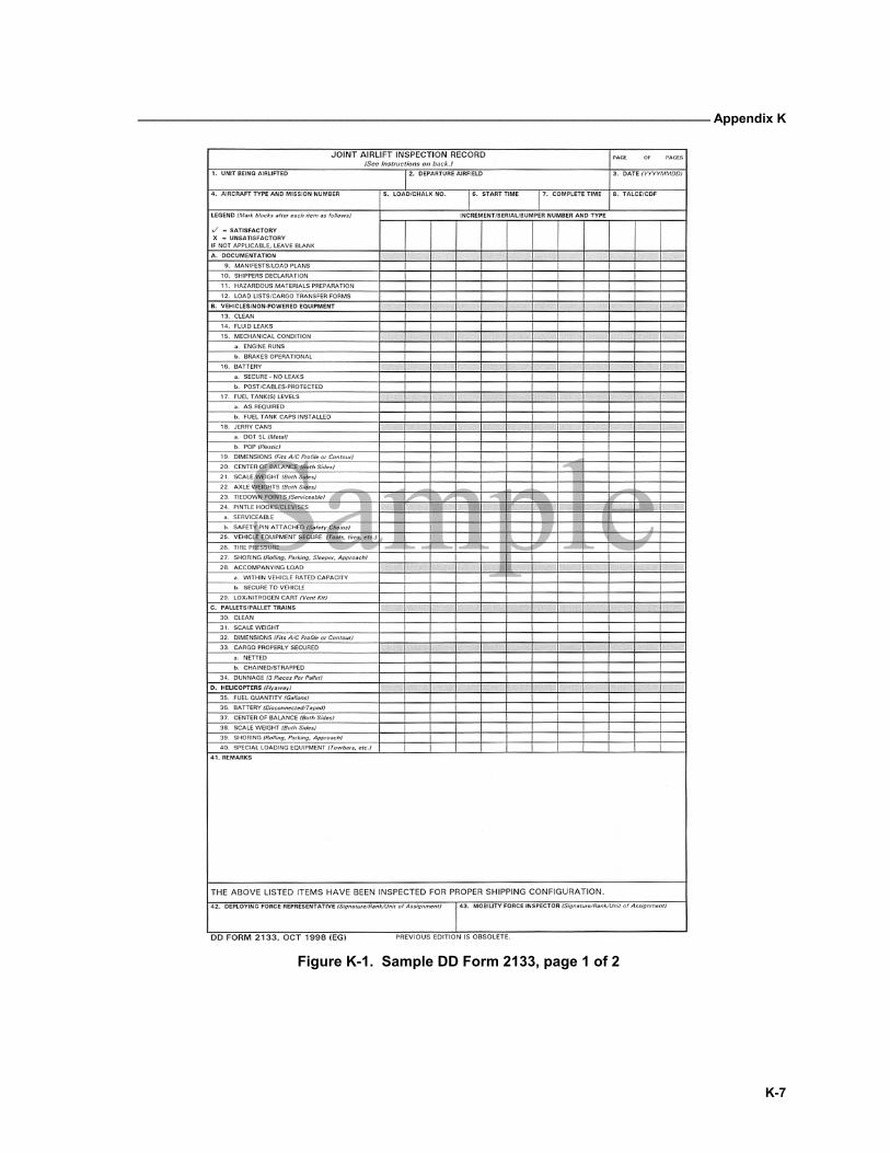
_______________________________________________________________________________ Appendix K
K-7
Figure K-1. Sample DD Form 2133, page 1 of 2
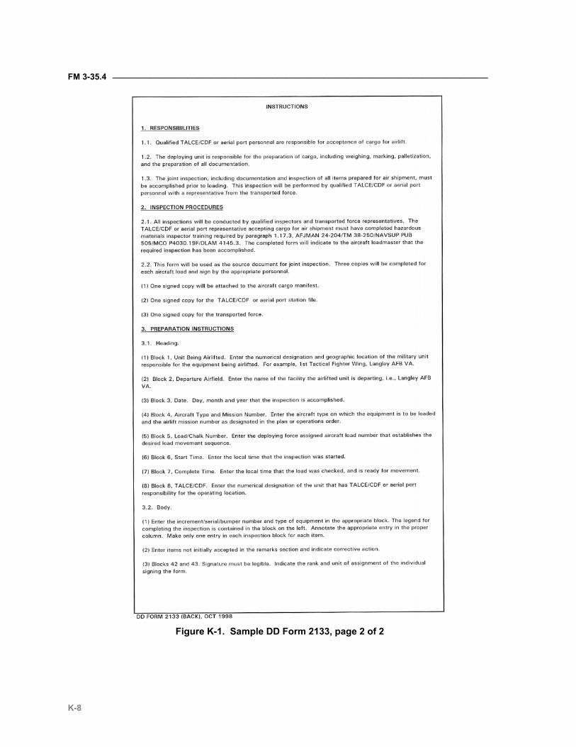
FM 3-35.4 ________________________________________________________________________________
K-8
Figure K-1. Sample DD Form 2133, page 2 of 2
L-1
Appendix L
Deploying Unit Departure Airfield Control Group Planning and Preparation Phase Requirements
The Departure Airfield Control Group (DACG) is the organization pro-vided by the FORSCOM-designated installation, which will control the unit airlifted from the marshaling area until released to the TALCE at the ready line. Listed below are responsibilities for the readiness of the deploying units.
DEPLOYING UNIT The deploying unit will— • Identify the number of personnel to be moved. • Identify the type and quantity of cargo and equipment to be moved. • Establish priorities for arrival. • Establish required liaison. • Identify the cargoes or equipment that require special handling based on
shipping configuration or fragile/hazardous characteristics. • Request technical assistance to prepare equipment and train personnel. • Plan and coordinate staff assistance in administrative support, unit
movement training, air movement planning, logistics and maintenance support and standard safety practices in and around aircraft.
• Assign unit movement or embarkation officer. • Develop traffic plan for movement to the departure airfield. • Establish trained load teams to assist the D/AACG. • Identify foreign border clearance requirements if applicable. • Enter force deployment requirements into the JOPES to accurately re-
flect lift requirements and deployment priorities. • Determine requirements for vehicle cargo restraint devices. • Review inspection procedures and documentation requirements for haz-
ardous cargo. • Coordinate procedures for transporting individual weapons, ammunition,
and equipment. • Determine shoring requirements, ensure its availability before loading,
and establish destination disposition procedures. • Construct 463L pallets in accordance with DoD 4500.9R. • Prepare vehicles and equipment in accordance with DoD 4500.9R.
FM 3-35.4 ________________________________________________________________________________
L-2
DEPARTURE AIRFIELD CONTROL GROUP The DACG will— • Determine the number of personnel to be moved. • Determine the type and quantity of cargo and equipment to be moved. • Determine the timeframe for loading. • Confirm the location of airfield(s) and marshaling area(s) with the instal-
lation or base commander and the deploying unit. • Determine available departure airfield logistics and administrative facili-
ties. • Determine user support requirements (MHE, security, lighting, fuels,
etc.) • Establish liaison with the deploying unit and other support activities. • Coordinate with the TALCE to establish DACG training requirements. • Coordinate foreign border clearance requirements and procedures if nec-
essary. • Obtain UDL of unit cargo and equipment to be loaded. Identify any prob-
lems that will affect loading or require special attention to the TALCE. • Validate shoring requirements. • Ensure 463L pallet dunnage availability.
M-1
Appendix M
Labeling and Tagging Equipment
Unit equipment and sustainment cargo, (such as vehicles, containers, and 463L pallets), moving in a force projection operation should be labeled and tagged with AIT data storage devices. This appendix describes label-ing requirements and provides a set of checks to assist organizations in applying AIT data storage devices to equipment. If applied properly these devices can be efficiently utilized throughout the mobilization, deploy-ment redeployment, and demobilization (MDRD) process to automatically collect and report supply and ITV data.
ESTABLISHED REQUIREMENTS M-1. Current Army guidance only addresses attaching military shipping labels to equipment and containers. There are no standards for attaching RFID tags. Current requirements are— • All containers will display two military shipping labels. One label is
placed on a container door and the other on the adjacent side. (See Figure M-1 for an example of where to attach MSLs to container shipments.)
• For vehicles, one label will be attached to the left front bumper (driver’s side), and the other label will be placed on the left side door (driver’s door). (See Figure M-1.)
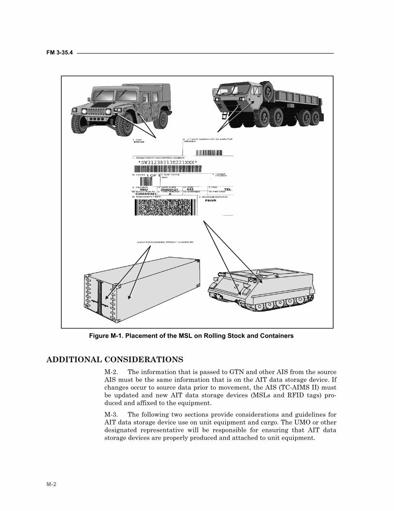
FM 3-35.4 ________________________________________________________________________________
M-2
Figure M-1. Placement of the MSL on Rolling Stock and Containers
ADDITIONAL CONSIDERATIONS M-2. The information that is passed to GTN and other AIS from the source AIS must be the same information that is on the AIT data storage device. If changes occur to source data prior to movement, the AIS (TC-AIMS II) must be updated and new AIT data storage devices (MSLs and RFID tags) pro-duced and affixed to the equipment.
M-3. The following two sections provide considerations and guidelines for AIT data storage device use on unit equipment and cargo. The UMO or other designated representative will be responsible for ensuring that AIT data storage devices are properly produced and attached to unit equipment.
_______________________________________________________________________________Appendix M
M-3
MILITARY SHIPPING LABELS M-4. The following general guidelines should be considered when working with, and attaching MSLs to unit equipment: • Whenever possible, use Mylar MSLs. They are more resistant to damage
by the weather. If paper MSLs are used, ensure they are laminated or otherwise protected from the elements. Ensure the label can still be scanned through the lamination or protective material. Ensure that every piece of equipment on the UDL has two military shipping labels produced and attached.
• Ensure all required data fields are filled out correctly before printing the labels.
• After producing the MSLs, scan the bar codes to ensure they are readable and accurate.
• Ensure the correct MSLs are attached to the proper piece of equipment in such a manner to reasonably ensure they will not be lost or destroyed during transit.
• When attaching MSLs, ensure the surface area where the label will be attached is clean. This allows the adhesive on the label to stick.
• After attaching the MSLs, visually check to ensure they are properly at-tached and were not damaged during placement on the equipment. Scan the bar codes to ensure that the correct MSLs are on the correct piece of equipment.
• For items that do not possess the physical characteristics of the equip-ment in paragraph M–1, follow these general guidelines when attaching MSLs. For equipment without bumpers or doors, attach the MSL in a simi-
lar position (left front and left side). Ensure the labels can be easily found by individuals that need to scan the data at the various transit locations.
Do not attach the label to a part of the equipment that may be re-moved and packed separately during the movement. (For example, do not attach an MSL to the driver’s door of a soft-top high mobility mul-tipurpose wheeled vehicle (HMMWV) if the door will be removed and packed before loading strategic transportation.)
• Attach MSLs to 463L pallets and other multipacks the same as contain-ers. Place MSLs on one end and on the adjacent side at the same end of the multipack or pallet.
• Do not mark on the code 3-of-9 or portable data file (PDF)-417 symbology on the MSLs. If local procedures require operators to physically mark the label after it has been scanned (to provide a visual check showing the bar code has been read), mark somewhere other then the symbologies. Mark-ing over the code 3-of-9 or (PDF)-417 symbology may make the linear and 2D bar code unreadable at other transit locations.
RADIO FREQUENCY TAGS M-5. The following general guidelines should be considered when working with, and attaching RFID tags to unit equipment.
FM 3-35.4 ________________________________________________________________________________
M-4
• When burning RFID tags, interrogate the tag after the burn to ensure that the data transferred correctly. • Ensure the RFID tag is attached to the correct piece of equipment.
When attaching RFID tags to equipment, consider the following guidelines:
Attach the RFID tags in a location that reasonably assures they can be interrogated as they flow through the movement process with the piece of equipment. The RFID tags must be on the out-side of the piece of equipment.
Develop a method to attach the RFID tags so that they will not be lost or damaged in shipment. Plastic ‘zip’ strips, nylon strips, or magnetic holders have worked well in previous operations. (Note: previous operations have shown that the plastic strips are not as durable as the nylon strips.) Tie down both the top and the bot-tom of the tag so that it will not bounce and be damaged during shipment.
When attaching the newer 410 tag to containers, mount them on the right side near the top. Ensure that the RFID tag is mounted between the ribs in an indentation. When attaching the older SealTag II RFID tags, use the nylon strips and mount them to the front door.
When attaching RFID tags to vehicles, tie the tag to the top of the grill using two long nylon strips to attach the device ensures the tag will not bounce or be lost during transit.
Attach RFID tags on 463L pallet netting using nylon strips. Put the tag near the MSL.
When attaching RFID tags on other equipment, mount the tag so that it can easily be read but not damaged. Use nylon or plastic strips to attach the tag.
Do not drill holes in equipment without prior approval from the owners. (In previous operations, organizations have created brackets to attach RFID tags to containers. Mounting the brack-ets required drilling holes in the commercial containers. As prior approval to drill the holes was not obtained from the container owner, DoD paid for the damage.)
Verify the battery life of RFID tags. If the battery power is low, replace the batteries. RFID tags with low battery power will not operate properly and will not respond to interrogator ‘wake up’ calls. The process of checking RFID tag batteries, as equipment and sustainment supplies flow through the force projection pipe-line will require advanced planning. For example, the newer 410 tag has two mounting holes (one at the top and one at the bot-tom). When the tag is attached to a vehicle, for example an M923 5-ton cargo truck, zip strips are used to fasten the top and bottom of the tag to the front grill of the truck. In order to turn the tag over and replace the batteries at least one of the zip strips will have to be cut or broken. Procedures must be in place so that the individual checking tag batteries can quickly and easily break the zip strip, replace the batteries, and then replace the zip strip en-

_______________________________________________________________________________Appendix M
M-5
suring that the tag is once again securely fastened to the vehicle. If only one end of the tag is fastened to the vehicle the tag will bounce around during movement and may be damaged or lost.

Glossary-1
Glossary
2D two dimensional
A/C aircraft
A/DACG arrival/departure airfield control group
AALPS Automated Air Load Planning System
AAR Association of American Railroads
ABL ammunition basic load
AC Active component
AFB Air Force Base
AFJM Air Force Joint Manual
AI artificial intelligence
AIS automated information system
AIT automatic identification technology; advanced individual train-ing
AMC Air Mobility Command (Air Force)
AMC Army Materiel Command (Army)
AOR Area of Responsibility
AO area of operations
AOC area of concentration
APFT Army Physical Fitness Test
APOD aerial port of debarkation
APOE aerial port of embarkation
AR Army regulation
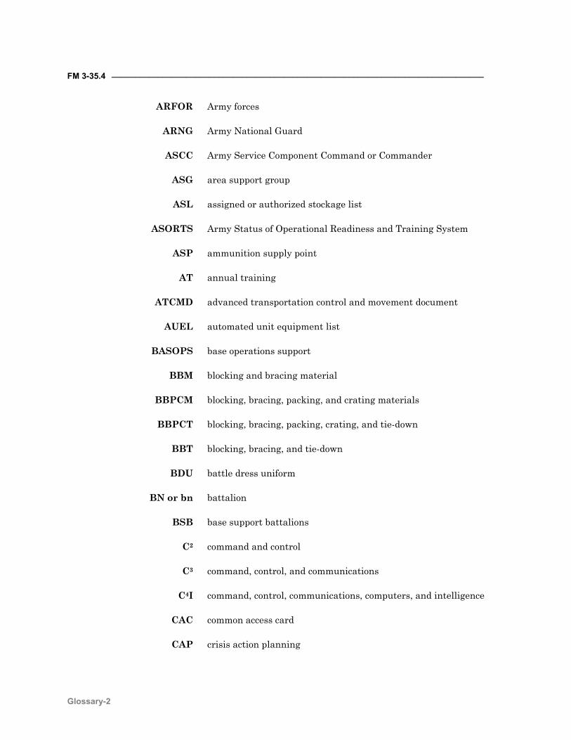
FM 3-35.4 ________________________________________________________________________________
Glossary-2
ARFOR Army forces
ARNG Army National Guard
ASCC Army Service Component Command or Commander
ASG area support group
ASL assigned or authorized stockage list
ASORTS Army Status of Operational Readiness and Training System
ASP ammunition supply point
AT annual training
ATCMD advanced transportation control and movement document
AUEL automated unit equipment list
BASOPS base operations support
BBM blocking and bracing material
BBPCM blocking, bracing, packing, and crating materials
BBPCT blocking, bracing, packing, crating, and tie-down
BBT blocking, bracing, and tie-down
BDU battle dress uniform
BN or bn battalion
BSB base support battalions
C2 command and control
C3 command, control, and communications
C4I command, control, communications, computers, and intelligence
CAC common access card
CAP crisis action planning
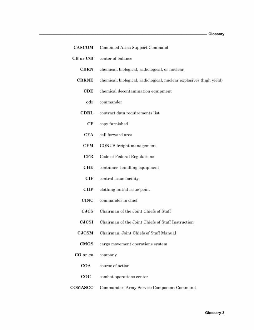
_________________________________________________________________________________ Glossary
Glossary-3
CASCOM Combined Arms Support Command
CB or C/B center of balance
CBRN chemical, biological, radiological, or nuclear
CBRNE chemical, biological, radiological, nuclear explosives (high yield)
CDE chemical decontamination equipment
cdr commander
CDRL contract data requirements list
CF copy furnished
CFA call forward area
CFM CONUS freight management
CFR Code of Federal Regulations
CHE container−handling equipment
CIF central issue facility
CIIP clothing initial issue point
CINC commander in chief
CJCS Chairman of the Joint Chiefs of Staff
CJCSI Chairman of the Joint Chiefs of Staff Instruction
CJCSM Chairman, Joint Chiefs of Staff Manual
CMOS cargo movement operations system
CO or co company COA course of action COC combat operations center
COMASCC Commander, Army Service Component Command
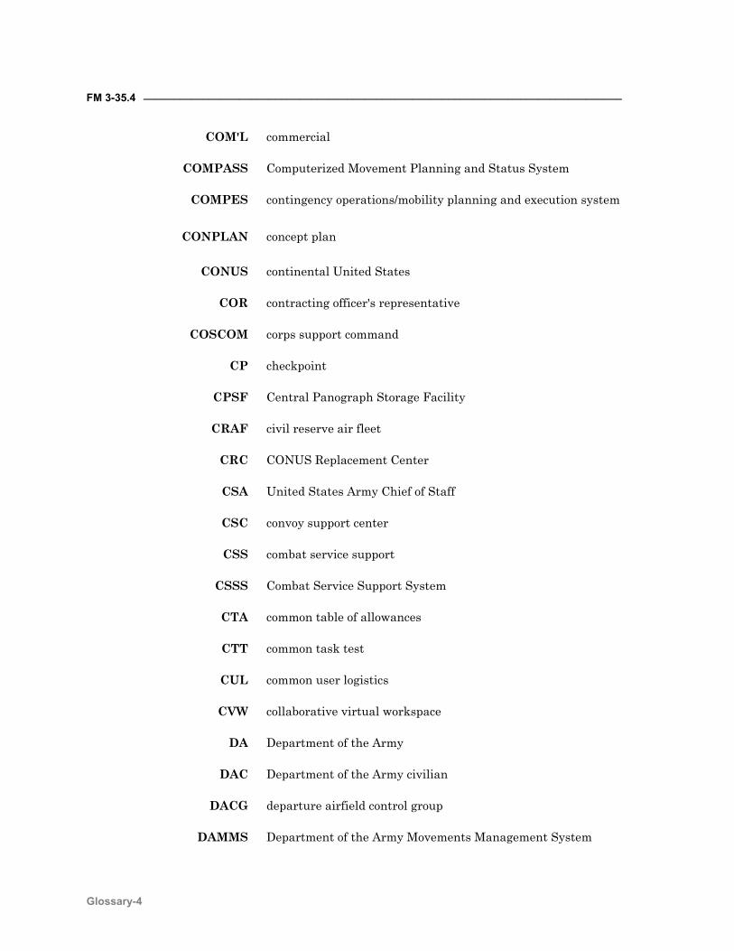
FM 3-35.4 ________________________________________________________________________________
Glossary-4
COM'L commercial
COMPASS Computerized Movement Planning and Status System
COMPES contingency operations/mobility planning and execution system
CONPLAN concept plan
CONUS continental United States
COR contracting officer's representative
COSCOM corps support command
CP checkpoint
CPSF Central Panograph Storage Facility
CRAF civil reserve air fleet
CRC CONUS Replacement Center
CSA United States Army Chief of Staff
CSC convoy support center
CSS combat service support
CSSS Combat Service Support System
CTA common table of allowances
CTT common task test
CUL common user logistics
CVW collaborative virtual workspace
DA Department of the Army
DAC Department of the Army civilian
DACG departure airfield control group
DAMMS Department of the Army Movements Management System

FM 3-35.418 JUNE 2002
By Order of the Secretary of the Army:
ERIC K. SHINSEKIGeneral, United States Army
Chief of Staff
Official:
JOEL B. HUDSONAdministrative Assistant to the
Secretary of the Army 0214310
DISTRIBUTION:
Active Army, Army National Guard, and U.S. Army Reserve: To be distributed inaccordance with the initial distribution number 115867, requirements for FM 3-35.4.
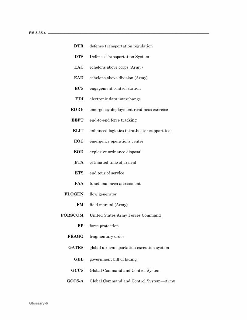
FM 3-35.4 ________________________________________________________________________________
Glossary-6
DTR defense transportation regulation
DTS Defense Transportation System
EAC echelons above corps (Army)
EAD echelons above division (Army)
ECS engagement control station
EDI electronic data interchange
EDRE emergency deployment readiness exercise
EEFT end-to-end force tracking
ELIT enhanced logistics intratheater support tool
EOC emergency operations center
EOD explosive ordnance disposal
ETA estimated time of arrival
ETS end tour of service
FAA functional area assessment
FLOGEN flow generator
FM field manual (Army)
FORSCOM United States Army Forces Command
FP force protection
FRAGO fragmentary order
GATES global air transportation execution system
GBL government bill of lading
GCCS Global Command and Control System
GCCS-A Global Command and Control SystemArmy
_________________________________________________________________________________ Glossary
Glossary-7
GDSS Global decision support system
GIS Graphic Information System
GOPAX Groups Operational Passenger System
GTN Global Transportation Network
HAZMAT hazardous material
HET heavy equipment transporter
HHC headquarters and headquarters company
HHT headquarters and headquarters troop
HHG household goods
HHI hand−held interrogator
HIV Human Immunodeficiency Virus
HMMWV high mobility multipurpose wheeled vehicle
HN host nation
HNS host nation support
HQ headquarters
HS home station
IA interface agreements
IAW in accordance with
IBCT interim brigade combat team
IBS integrated booking system
ICODES Integrated Computerized Deployment System
ID identification
IMA individual mobilization augmentee
FM 3-35.4 ________________________________________________________________________________
Glossary-8
IMDGC International Maritime Dangerous Goods Code
IMDG international maritime dangerous goods
IPR in-process review
IRR Individual Ready Reserve
ISB intermediate staging base
ISSA inter-service support agreement
ISU internal airlift/helicopter slingable-container unit
ITO installation transportation office
ITV in-transit visibility
IWS information workspace
JA/ATT joint airborne/air transportability training
JET JOPES editing tool
JFAST joint flow and analysis system for transportation
JFCOM Joint Forces Command
JFRG II joint force requirements generator II
JFTR joint federal travel regulation
JI joint inspection
JOPES Joint Operation Planning and Execution System
JP joint publication
JPEC joint planning and execution community
JPMO Joint Project Management Office
JRSOI joint reception, staging, onward movement, and integration
JSCP Joint Strategic Capabilities Plan
_________________________________________________________________________________ Glossary
Glossary-9
JTTP joint tactics, techniques, and procedures
K thousand
KFOR Kosovo Peacekeeping Force
LAN local area network
LMSR large, medium speed roll−on/roll−off
LOC line of communications
LOGMARS logistics applications of automated marking and reading sym-
bols
LOGMOD logistics module
LOI letter of instruction
LOLO lift−on/lift−off
LOX liquid oxygen
MA marshaling area
MACOM major command or major Army command
MAGTF Marine Air-Ground Task Force
MAGTF II Marine Air-Ground Task Force War Planning System II
MAIRS Military Airlift Integrated Reporting System
MAER manpower and personnel
MATES maneuver area training equipment site
MCC Movement Control Center
MCO Marine Corps order
MCOP Marine Corps Operations Pamphlet
MDRD mobilization, deployment, redeployment, demobilization
FM 3-35.4 ________________________________________________________________________________
Glossary-10
MDSS Mobilization Decision Support System; medical support battal-ion
METL mission−essential task list
METT-TC mission, enemy, terrain, troops, time available, and civilian con-siderations
MHE material handling equipment
MI middle initial
MISC miscellaneous
MMRB Military Medical Reclassification Board
MO movement orders
MOB mobilization
MOB/ODEE mobilization, operations, deployment, employment, and execu-
tion
MOBCON Mobilization Movement Control
MOOTW military operations other than war
MOS military occupational specialty
MRC major regional conflict
MRE meal, ready to eat
MRX mission rehearsal exercises
MS mobilization station/site
MSC Military Sealift Command
MSC major subordinate command
MSL military shipping label
MSR main supply route
MTF medical treatment facility
_________________________________________________________________________________ Glossary
Glossary-11
MTMC Military Traffic Management Command
MTMCTEA Military Traffic Management Command Transportation Engi-neering Agency
MTOE modified table of organization and equipment
MTW major theater war
MUSARC major United States Army reserve command
N/A or NA not applicable
NAAK nerve agent antidote kit
NAPP nerve agent pyridostigmine pretreatment
NAVSUP naval supply
NBC nuclear, biological, and chemical
NCA National Command Authorities
NCO noncommissioned officer
NCOIC noncommissioned officer in charge
NEW net explosive weight
N-Hour notification hour
NHTN National Highway Transportation Network
NLT not later than
NRP nonunit−related personnel
NVG night vision goggles
O&O operational and organizational
OCC officer course code
OCIE organizational clothing and individual equipment
OCONUS outside the Continental United States
FM 3-35.4 ________________________________________________________________________________
Glossary-12
ODEE operations, deployment, employment, and execution
OEL organization equipment list
OMC optical memory card
OOTW operations other than war
OPLAN operational/operations plan
OPORD operational order
OPP off-load preparation party
OPSEC operations security
PAX passenger
PC personal computer
PCMCIA Personal Computer Memory Card International Association
PDF portable data file
PLL prescribed load list
PMCS preventative maintenance checks and services
POC port operations center
POD port of debarkation
POE port of embarkation
POL petroleum, oil, and lubricants
POM program objective memorandum
POP performance oriented packaging
POV personally/privately owned vehicle
PW prisoner of war
PPP power projection platform
_________________________________________________________________________________ Glossary
Glossary-13
PSA port support activity
PSP power support platform
PSRC presidential selective reserve callup
PUB publication
QD quantity distance
RAA rear assembly area
RC Reserve component
RF radio frequency
RFDC radio frequency data communications
RFID radio frequency identification
RGATES Remote Global Air Transportation Execution System
RITV remote in−transit visibility
RO/RO roll−on/roll−off
ROA restricted operations area
RQT rapid query tool
RR railroad
RSC regional support command
RSO&I reception, staging, onward movement, and integration
RSOP readiness standard operating procedures
S-3 operations/training officer
S-4 logistics officer
S-A staging area
SAAM special assignment airlift mission
FM 3-35.4 ________________________________________________________________________________
Glossary-14
SAEDA subversion and espionage directed against US Army and delib-
erate security violations
SAMS Standard Army Maintenance System
SARSS Standard Army Retail Supply System
SASO stability and support operations
SECDEF Secretary of Defense
SEDRE Sealift Emergency Deployment Readiness Exercise
SERE survival, evasion, resistance, and escape
SF standard form
SI support installations
SIDPERS-3 Standard Installation/Division Personnel System
SOFA Status−of−Forces Agreement
SOP standard operating procedures
SORTS Status of Resources and Training System
SPBS-R Standard Property Book System−Redesign
SPOD seaport of debarkation
SPOE seaport of embarkation
SRP soldier readiness processing
SSA supply support activity
SSC small-scale contingency
SSN social security number
STARC State area coordinators
STB super tropical bleach
_________________________________________________________________________________ Glossary
Glossary-15
SUN shipment unit number
TAA tactical assembly area
TALCE tanker airlift control element
TAT to accompany troops
TB technical bulletin
TC-ACCIS Transportation Coordinators Automated Command and Con-trol Information System
TC-AIMS II Transportation Coordinators' Automated Information for Move-ments System II
TCMD transportation control and movement document
TCN transportation control number
TDA Table of Distribution and Allowances
TEA Transportation Engineering Agency
TM technical manual
TMDE test, measurement, and diagnostic equipment
TMO traffic management office; transportation management officer
TMP transportation motor pool
TOE table of organization and equipment
TPFDD time−phased force deployment data
TPFL time−phased forces and deployment list
TPU troop program unit; tank pump unit
TRADOC United States Army Training and Doctrine Command
TRAMS Transportation Automated Measurement System
TRML terminal
TSB transportation support brigade or theater staging base
FM 3-35.4 ________________________________________________________________________________
Glossary-16
TTB transportation terminal battalion
TTP tactics, techniques, and procedures
TTU transportation terminal unit
TUCHA type unit characteristics
TUDET type unit equipment detail file
UBL unit basic load
UDL unit deployment list
UIC unit identification code
ULL unit level logistics
ULN unit line number
UMC unit movement coordinator
UMD unit movement data
UMNCO unit movement noncommissioned officer
UMO unit movement officer
UMT unit movement teams
U.S. United States
USAF United States Air Force
USAR United States Army Reserve
USARC United States Army Reserve Command
USAREUR United States ArmyEurope
USCG United States Coast Guard
USDA United States Department of Agriculture or Army
USMC United States Marine Corps
_________________________________________________________________________________ Glossary
Glossary-17
USPFO United States Property and Fiscal Officer
USTRANSCOM United States Transportation Command
UTC unit type code
UTES unit raining equipment site
VA Virginia
WARNORD warning order
WETS week−end training site
WPS Worldwide Port System
X-Hour time crisis planning sequence is initiated by a warning order
(precedes N−hour)

Bibliography-1
Bibliography
DOCUMENTS NEEDED These documents should be available to the intended users of this publication.
CF 4455, Custom’s Certificate of Registration, U.S. Department of the Treasury.
CF 4457, Certificate of Registration for Personal Effects Taken Abroad, U.S. Department of the Treasury.
Except where otherwise indicated, the following DA forms are available on the Army Electronic Library (AEL) CD-ROM (EM 0001) and the USAPA web site (www.usapa.army.mil); DD forms are available from the OSD web site (www.dior.whs.mil/ICDHOME/DDEFORMS.HTM).
DA Form 2062, Hand Receipt/Annex Number, January 1982.
DA Form 3645, Organizational Clothing and Individual Equipment Record, October 1991.
DA Form 3955, Change of Address and Directory Card, February 1979. (Available through nor-mal forms supply channels.)
DA Form 4283, Facilities Engineering Work Request, August 1978. (Available through normal forms supply channels.)
DA Form 4886, Issue-In-Kind-Personal Clothing Record, May 1993.
DA Form 5748-R, Shipment Unit Packing List and Load Diagram, March 1989.
DA Form 7425, Readiness and Deployment Checklist, July 2001.
DD Form 603, Registration of War Trophy Firearm, October 1951.
DD Form 626, Motor Vehicle Inspection, September 1998.
DD Form 836, Dangerous Goods Shipping Paper/Declaration and Emergency Response Informa-tion for Hazardous Materials Transported by Government Vehicles/Containers and Ves-sels, January 2001.
DD Form 1253, Military Customs Inspection (Label), April 1977. (Available through normal forms supply channels.)
DD Form 1253-1, Military Inspection Customs (Tag), April 1977. (Available through normal forms supply channels.)
DD Form 1265, Request for Convoy Clearance, September 1998.
DD Form 1266, Request for Special Hauling Permit, September 1998.
DD Form 1387, Military Shipment Label, July 1999.
DD Form 1387-2, Special Handling Data/Certification, June 1996.
FM 3-35.4 ________________________________________________________________________________
Bibliography-2
DD Form 1726, CONUS Military Installation Materiel Outloading and Receiving Capability Re-port, January 2000.
DD Form 1750, Packing List, September 1970.
DD Form 1907, Signature and Tally Record, May 2000.
DD Form 2130-1, C-5 A/B Cargo Manifest, September 1998.
DD Form 2130-3, C-141B Cargo Manifest, September 1998.
DD Form 2130-6, KC-10A Load Plan (17 pallets configuration), September 1998.
DD Form 2131, Passenger Manifest, September 1998.
DD Form 2133, Joint Airlift Inspection Record, October 1998.
DD Form 2271, Decontamination Tag, November 1982.
DD Form 2775/AF Form 2279, Pallet Identifier, September 1998.
DD Form 2777, Mobilization Movement Control (MOBCON) Request for Convoy Clearance or Special Hauling Permit, September 1998.
MISC Pub 55-3, Shipper's Declaration for Dangerous Goods, 1995
TM 38-250, Preparing Hazardous Materials for Military Air Shipments, March 1997
JOINT AND MULTISERVICE PUBLICATIONS Most joint publications are online at http://www.dtic.mil/doctrine/
CJCSI 3020.01, Managing, Integrating, and Using Joint Deployment Information Systems, June 2000.
CJCSI 3100.01A, Joint Strategic Planning System, September 1999.
CJCSM 3113.01A, Theater Engagement Planning, May 2000.
CJCSM 3500.04B, Universal Joint Task List, Change 1, November 1999.
DOD Directive 1400.31, DOD Civilian Work Force Contingency and Emergency Planning and Execution, April 1995.
DOD Directive 1404.10, Emergency-Essential (E-E) DOD U.S. Citizen Civilian Employees, April 1992.
DOD Directive 4500.9-R, Defense Transportation Regulation-Part II, Cargo Movement, December 2000.
DOD Directive 4500.9-R, Defense Transportation Regulation-Part III, Mobility, November 2001.
DOD Directive 4500.36-R, Management, Acquisition, and Use of Motor Vehicles, March 1994.
______________________________________________________________________________ Bibliography
Bibliography-3
DOD Directive 4525.6-M, DOD Postal Manual, December 1989.
DOD Instruction 1400.32, DOD Civilian Work Force Contingency and Emergency Planning Guidelines and Procedures, April 1995.
Joint Federal Travel Regulation: Uniformed Services Personnel, JFTR Volume l, revised as needed.
Joint Travel Regulation: DOD Civilian Personnel, JTR Volume 2, revised as needed.
JP 0-2, Unified Action Armed Forces (UNAAF), July 2001.
JP 1, Joint Warfare of the Armed Forces of the United States, November 2000.
JP 1-02, DOD Dictionary of Military and Associated Terms, April 2001. (Amended through 23 January 2002).
JP 3-0, Doctrine for Joint Operations, September 2001.
JP 3-07.2, JTTP for Antiterrorism, 17 March 1998.
JP 3-35, Joint Deployment and Redeployment Operations, September 1999.
JP 4-0, Doctrine for Logistic Support of Joint Operations, April 2000.
JP 4-01, Joint Doctrine for the Defense Transportation System, June 1997.
JP 4-01.2, Joint Tactics, Techniques and Procedures (JTTP) for Sealift Support to Joint Opera-tions, October 1996.
JP 4-01.3, JTTP for Movement Control, June 1996.
JP 4-01.5, Joint Tactics, Techniques, and Procedures for Water Terminal Operations, June 1996.
JP 4-01.8, Joint Tactics, Techniques and Procedures for Joint Reception, Staging, Onward Movement, and Integration, June 2000.
JP 4-05, Joint Doctrine for Mobilization Planning, June 1995.
JP 4-05.1, Joint, Tactics Techniques, and Procedures for Manpower Mobilization and Demobili-zation Operations: Reserve Component Call-up, November 1998.
JP 5-0, Doctrine for Planning Joint Operations, April 1995.
TM 38-250, Preparing Hazardous Materials for Military Air Shipments, March 1997. (AFJM 24-204, NAVSUP Pub 505, MCOP 4030.19F, DLAM 4145.3)
ARMY PUBLICATIONS Most Army doctrinal publications are online at http:www.adtdl.army.mil/atdls.html or at http://www.lia.army.mil/dpmsh/pubs_rev_dt.html
AR 10-87, Major Army Commands in the Continental United States, October 1992.
FM 3-35.4 ________________________________________________________________________________
Bibliography-4
AR 11-30, WARTRACE Program, July 1995.
AR 27-3, The Army Legal Assistance Program, September 1992.
AR 37-104-4, Military Pay and Allowances Policy and Procedures - Active Component, September 1994.
AR 40-3, Medical, Dental, and Veterinary Care, July 1999.
AR 40-501, Standards of Medical Fitness, August 1995.
AR 55-80, Highways for National Defense, December 1982. AR 59-9, Special Assignment Airlift Mission Requirements, March 1985.
AR 135-133, Ready Reserve Screening, Qualification Records System, and Change of Address Re-ports, August 1984.
AR 135-210, Order to Active Duty as Individuals for Other Than a Presidential Selected Reserve Call-up, Partial or Full Mobilization, December 1996.
AR 140-1, Mission, Organization, and Training, September 1994.
AR 140-145, Individual Mobilization Augmentation (IMA) Program, November 1994.
AR 190-11, Physical Security of Arms, Ammunition, and Explosives, September 1993.
AR 190-13, The Army Physical Security Program, September 1993
AR 220-1, Unit Status Reporting, November 2001.
AR 220-10, Preparation for Oversea Movement of Units (POM), June 1973.
AR 310-25, Dictionary of United States Army Terms, October 1983.
AR 380-5, Department of the Army Information Security Program, September 2000.
AR 500-5, Army Mobilization, June 1996.
AR 500-10, Nonindustrial Facilities for Mobilization, November 1974.
AR 525-1, The Department of the Army Command and Control System (DACCS), December 1985.
AR 600-8-101, Personnel Processing (In- and Out- and Mobilization Processing), December 1989.
AR 601-10, Management and Mobilization of Retired Soldiers of the Army, November 1994.
AR 604-10, Military Personnel Security Program, April 1975.
AR 614-30, Overseas Service, August 2001.
AR 635-200, Enlisted Personnel, November 2000.
AR 670-1, Wear and Appearance of Army Uniforms and Insignia, September 1992.
______________________________________________________________________________ Bibliography
Bibliography-5
AR 672-20, Incentive Awards, June 1993.
AR 690-11, Mobilization Planning and Management, September 1990.
AR 700-137, Logistics Civil Augmentation Program (LOGCAP), December 1985.
AR 710-2, Inventory Management Supply Policy Below the Wholesale Level, October 1997.
CTA 50-900, Clothing and Individual Equipment, September 1994.
DA Pam 350-38, Standards in Weapons Training, July 1997.
DA Pam 600-41, Military Personnel Managers Mobilization Handbook, January 1987.
DA Pam 600-72, Army Manpower Mobilization, July 1990.
DA Pam 690-47, Civilian Personnel Handbook, DA Civilian Employee Deployment Guide New In-formational Handbook, November 1995.
FM 3-0 (100-5), Operations, June 2001.
FM 3-19.30 (19-30), Physical Security, January 2001.
FM 9-207, Operations and Maintenance of Ordnance Materiel in Cold Weather, March 1998. (Will be revised as FM 4-30.32)
FM 10-23, Basic Doctrine for Army Field Feeding and Class I Operations Management, April 1996. (Will be revised as FM 4-20.2)
FM 12-6, Personnel Doctrine, September 1994. (Will be revised as FM 1-0)
FM 16-1, Religious Support, May 1995. (Will be revised as FM 1-05)
FM 27-100, Legal Support to Operations, March 2000. (Will be revised as FM 1-04)
FM 54-30, Corps Support Groups, June 1993. (Will be revised as FM 4-93.30)
FM 54-40, Area Support Group, October 1995. (Will be revised as FM 4-93.40)
FM 55-1, Transportation Operations, October 1995. (Will be revised as FM 4-01)
FM 55-9, Unit Air Movement Planning, April 1993. (To be incorporated into 4- 01.011, Strategic Lift).
FM 55-10, Movement Control, February 1999. (Will be revised as FM 4-01.30)
FM 55-15, Transportation Reference Data, October 1997. (To be incorporated into 4-01.011, Stra-tegic Lift).
FM 55-17, Cargo Specialists’ Handbook, February 1999. (Will be revised as FM 4-01.5)
FM 3-35.4 ________________________________________________________________________________
Bibliography-6
FM 55-20, Rail Transport in a Theater of Operations, June 2000. (To be incorporated into FM 4-01.41, Rail Transport in a Theater of Operations).
FM 55-21, Railway Operating and Safety Rules, July 1989. (To be incorporated into FM 4-01.41, Rail Transport in a Theater of Operations).
FM 55-30, Army Motor Transport Units and Operations, June 1997. (Will be revised as FM 4-01.40)
FM 55-60, Army Terminal Operations, April 1996. (To become 4-01.50, Transportation Intermo-dal Units and Operations).
FM 55-65, Strategic Deployment, October 1995. (To be incorporated into FM 4-01.011, Strategic Lift).
FM 63-3, Corps Support Command, September 1993. (Will be revised as FM 4-93.3)
FM 63-4, Combat Service Support Operations Theater Army Area Command, September 1984. (To be renamed Theater Support Command, upon update). (Will be revised as FM 4-93.4)
FM 63-11, Logistics Support Element Tactics, Techniques, and Procedures, October 1996. (Will be revised as FM 4-93.41)
FM 71-100, Division Operations, August 1996. (Will be revised as FM 3-19)
FM 90-3, Desert Operations, August 1993. (Will be revised as FM 3-97.3)
FM 100-7, Decisive Force: The Army in Theater Operations, May 1995. (Will be revised as FM 3-93)
FM 100-10, Combat Service Support, October 1995. (Will be revised as FM 4-0)
FM 100-10-2, Contracting Support on the Battlefield, August 1999. (Will be revised as FM 4-100.2)
FM 100-11, Force Integration, January 1998. (Will be revised as 3-100.11)
FM 100-14, Risk Management, April 1998. (Will be revised as FM 5-19)
FM 100-15, Corps Operations, October 1996. (Will be revised as FM 3-92)
FM 100-16, Army Operational Support, May 1995. (Will be revised as FM 3-100.16)
FM 100-17, Mobilization, Deployment, Redeployment, Demobilization, October 1992. (Will be re-vised as FM 3-35)
FM 100-17-1, Army Pre-positioned Afloat Operations, July 1996. (Will be revised as FM 3-35.1)
FM 100-17-2, Army Pre-positioned Land, February 1999. (Will be revised as FM 3-35.2)
FM 100-17-3, Reception, Staging, Onward Movement, and Integration, March 1999. (Will be re-vised as FM 4-01.8)
______________________________________________________________________________ Bibliography
Bibliography-7
FM 100-17-5, Redeployment, September 1999. (Will be revised as FM 3-35.5)
FM 100-21, Contractors on the Battlefield, March 2000. (Will be revised as FM 3-100.21)
FM 100-22, Installation Management, October 1994. (Will be revised as FM 7-22)
FM 100-23, Peace Operations, December 1994. (Will be revised as FM 3-07.3)
FM 101-5, Staff Organization and Operations, May 1997. (Will be revised as FM 5-0)
TB 43-0209, Color, Marking and Camouflage Painting of Military Vehicles, Construction Equip-ment, and Materials Handling Equipment, October 1990.
TB 43-0239, Maintenance in the Desert, October 1990.
TM 38-750, The Army Equipment Record System and Procedure.
COMMAND PUBLICATIONS FORSCOM/ARNG Regulation 55-1, Transportation and Travel, Unit Movement Planning, March
2000.
MTMCTEA Pamphlet 55-19, Tiedown Handbook for Rail Movements, May 2000.
MTMCTEA Pamphlet 70-1, Transportability for Better Deployability, September 1999.
MTMCTEA Pamphlet 96-55-23, Containerization of Military Vehicles, September 1997.
MTMCTEA Pamphlet 700-5, Deployment Planning Guide: Transportation Assets Required for Deployment, May 2001.
MTMCTEA Reference 96-55-20, Tiedown Handbook for Truck Movements, September 1997.
MTMCTEA Reference 96-55-24, Vehicle Preparation Handbook for Fixed Wing Air Movements, July 1999.
MTMCTEA Reference 97-55-22, Marine Lifting and Lashing Handbook, October 1996.
MTMCTEA Reference 98-55-21, Lifting and Tiedown of U.S. Military Helicopters for Marine Transport, January 2001.
MTMCTEA TB 55-46-1, Standard Characteristics for Transportability of Military Vehicles and Other Outsize/Overweight Equipment, January 2001.
TRADOC Regulation 350-6, Initial Entry Training (IET) Policies and Administration, November 1998.
OTHER PUBLICATIONS Arana-Barradas, MSG Louis A., Rhein-Main Still at Center Stage, May 2000. Available:
www.af.mil/news/May2000/n20000524_000804.html
FM 3-35.4 ________________________________________________________________________________
Bibliography-8
Cohen, William S., Security in a Grave New World, September 1998. Available: www.defenselink.mil/news/Sep1998/b09141998_bt475-98.html
Cohen, William S., Department of Defense Responsibilities for Force Protection, Memorandum for the Chairman Joint Chiefs of Staff, September 1996. Available: www.fas.org/irp/threat/downing/annx_d.html
DOT Exception 7280, Authorizes the transportation in commerce of certain motor vehicles, fixed wing aircraft, helicopters, air-cushioned vehicles/boats, and powerboats with fuel tanks ¾ full instead of ¼ full. November 1999.
DOT P 5800.5, United States Department of Transportation Emergency Response Guidebook, 1990.
Force Protection O&O, Final Draft. (Various). Appendix B: Security and Force Protection Issues for Deploying and In-Transit Forces. October 2001.
King, Benjamin, Richard C. Biggs, and Eric R. Criner. Spearhead of Logistics: A History of the U.S. Army Transportation Corps. 1994.
Kross, General Walter. Force Protection is Everybody’s Business, December 1996. Available: www.af.mil/news/Dec1996/n19961227_961326/html
MIL STD 209, Slinging and Tiedown Provisions for Lifting and Tying Down Military Equip-ment, January 2000.
MIL STD 669, Loading Environmental and Related Requirements for Platform Rigged Airdrop Materiel, February 1997.
MIL STD 810, Environmental Engineering Considerations and Laboratory Tests, November 1990.
MIL STD 814, Requirements for Tiedown, Suspension, and Extraction Provisions on Materiel for Airdrop, February 1999.
MIL STD 910, Mobile Tactical Systems Overload Prevention Procedures, 1990.
MIL STD 913, Requirements for the Certification of Externally Transported Military Equipment by Department of Defense Rotary Wing Aircraft, February 1997.
MIL STD 1791, Designing for Internal Aerial Delivery in Fixed Wing Aircraft, 1985.
Rule 2, Section 1, Association of American Railroads Open Top Loading Rules, Manuel, General Rules for Loading All Commodities on Open Top Cars.
Shun, CPT Ronald J. (1997 November-December). Automating Convoy Operations. Professional Bulletin of United States Army Logistics, 8-9.
Title 33 U.S. Code of Federal Regulations, Navigation and Navigable Waters, July 2000.
Title 49 U.S. Code of Federal Regulations, Transportation, October 2000.
______________________________________________________________________________ Bibliography
Bibliography-9
PROJECTED PUBLICATIONS Projected publications are sources of additional information that were scheduled for printing but not yet available at the time this manual went to print. When these publications are printed, they are distributed automatically via pinpoint distribution. Included are DOD, Joint, and Mul-tiservice publications used to prepare this manual which were available in draft when this man-ual was submitted for printing.
CJCSM 3122.01, Joint Operation Planning and Execution System, Volume 1, Planning Policies and Procedures, to be published.
CJCSM 3122.03, Joint Operation Planning and Execution System, Volume 2, Planning Formats and Guidance, to be published.
FM 3-100.35 (100-35), Force Protection, under development.
FM 4-01.41, Rail Transport in a Theater of Operations, publication to be determined. (Will con-solidate the contents of FMs 55-20 and 55-21).
FM 4-01.011, Strategic Deployment, publication to be determined. (Will consolidate the contents of FMs 55-9, 55-15, and 55-65).
FM 4-93.7 (63-7), Combat Service Support to the Interim Brigade Combat Team, under develop-ment.
FM 100-20, Stability and Support Operations.
JP 3-35, Joint Deployment and Redeployment Operations.
JP 4-01.8, Joint Tactics Techniques, and Procedures for Reception, Staging, Onward Movement, and Integration.
WEB SITES The following web sites were utilized during the development of this FM. These sites contain ad-ditional information on organizations described in the text or they contain documentation impor-tant to deployment.
United States Army: http://www.army.mil
Military Traffic Management Command (MTMC): http://www.mtmc.army.mil
Military Traffic Management Command Transportation Engineering Agency (MTMCTEA): http://www.tea.army.mil
Military Sealift Command (MSC): http://www.msc.navy.mil
United States Coast Guard (USCG): http://www.uscg.mil
Objective Force: http://www.army.mil/armyvision/default.htm
General Dennis J. Reimer Training and Doctrine Digital Library: http://www.adtdl.army.mil/ atdls.htm

FM 3-35.4 ________________________________________________________________________________
Bibliography-10
Listing of DD Forms: http://web1.whs.osd.mil/icdhome/ddeforms.htm
Joint Doctrine: http://www.dtic.mil/doctrine/
Index-1
Index A
AALPS. See automated air load planning system
A/DACG. See arrival/departure airfield control group
aerial port of embarkation, 3-11, 4-2, 4-11, 5-10, 5-11, 5-12, A-13, D-32, E-2, E-3, E-6, E-10
Air Mobility Command, 2-12, 3-6, 3-7, 4-12, 4-15, 5-11, 5-12, F-1
AIS. See automated information systems
AIT. See automatic identification technology
AMC. See Air Mobility Command AO. See area of operation APOE. See aerial port of embar-
kation area of operation, 1-3, 1-10, 2-8,
3-6, D-30 area support group, 4-5, 5-4, 5-
9, 5-16 ARFOR. Army forces Army forces, iv, v, 1-4 Army National Guard, D-1, D-3,
D-30, E-13 Army service component com-
mand, iv, v, 1-4, 1-6, 2-4, 2-11, 2-13, 4-4, D-1 Army transformation and de-
ployment, 1-9 initial force, 1-9 interim force, 1-9, B-1 objective force, 1-9, 1-10
ARNG. See Army National Guard
arrival/departure airfield control group, 2-10, 3-1, 3-31, 4-11 through 4-14, 5-5, 5-6, 5-10
ASG. See area support group ASCC. See Army service com-
ponent command
AUEL. See automated unit equipment list
automated air load planning sys-tem, 5-13, A-7, A-9, A-10, A-11
automated unit equipment list, 1-8, 1-9, E-13
automated information systems, 4-2, 5-2 through 5-17, A-5, A-7, M-2
automatic identification technol-ogy, 2-10, 4-5, 5-2 through 5-17, A-8 through A-10, M-1, M-2
automation and communication systems JOPES, A-1 through A-3 GTN, A-3 Global Command and Control
System (GCCS), A-3, A-4 Global Command and Control
System-Army, A-4 End-to-End Force Tracking
(EEFT), A-4 Global Decision Support Sys-
tem (GDSS), A-5 Combat Service Support Con-
trol System, A-5 COMPASS, A-5 JFRG II, A-5 WPS, A-5, A-6 TC-ACCIS, A-6, A-7 TC-AIMS II, A-7 through A-10 AALPS, A-10 Automated Movement Flow
Tracking System (AMFT), A-11
Department of the Army Movements Management System (DAMMS), A-11
Joint Flow and Analysis for Transportation (JFAST), A-11
Integrated Computerized De-ployment System (ICODES), A-11, A-12
Integrated Booking System (IBS), A-12
Enhanced Logistics Intrathea-ter Support Tool (ELIST), A-12
The CONUS Freight Man-agement System (CFM), A-12
MOBCON, A-13 GOPAX, A-13 Standard Installation/Division
Personnel 3 (SIDPERS-3), A-13
Standard Property Book Sys-tem-Redesign (SPBS-R), A-13
Unit Level Logistics System (ULLS), A-14
Cargo Movement Operation System (CMOS), A-14
B
BBPCT. See blocking, bracing, packing, crating, and tie-down
blocking, bracing, packing, crat-ing, and tie-down, A-7, D-2, D-4, D-5, D-30 through D-32, E-7, E-10
C
CAC. See common access card CAP. See crisis action planning Chairman of the Joint Chiefs of
Staff, 1-7, 1-8, 2-3, A-2, B-1, B-2
Chief of Staff Army, 1-9 CINC. See commanders-in-chief CJCS. See Chairman of the
Joint Chiefs of Staff classified cargo, I-1 COMASCC. See Commander,
Army service component command
combat service support, 1-1, 1-4, 4-16, A-2
commanders, 1-2, 1-4, 2-7 through 2-9, 3-12, 4-7, A-2
Army service component com-mand, 1-4, 2-4, 2-12, 2-13
FM 3-35.4 _________________________________________________________________________________
Index-2
Army force commanders, 1-4 combatant commanders, 1-2, 2-
3, A-4 combat service support com-
manders, 3-11 commanders-in-chief, A-3 deploying unit commanders, 3-1,
3-4, 3-6, 5-6, A-7 through A-11
force-level commanders, 3-12, A-4
joint force commanders, 1-2, A-5 unit commanders, 3-12, 4-8 common access card, 3-4, 5-2
through 5-4, 5-8, 5-12, 5-17, A-8
COMPASS. See Computerized Movement Planning and Status System
Computerized Movement Plan-ning and Status System, 1-8, 2-3, 2-6, A-5, A-6
concept of operation plans, 2-3, A-1, D-2
CONPLAN. See concept of op-eration plans
convoy commander’s checklist, J-1 through J-4
crisis action planning, 2-3 through 2-5
CSA. See Chief of Staff Army CSS. See combat service sup-
port D
DACG. See departure airfield control group
Defense Movement Coordinator, 3-9, 4-3, E-3, E-13
defense transportation system, 1-4, K-1
DEL. See deployment equipment list
departure airfield control group, L-1, L-2
deployment, 1-3 binders, C-1, C-2 installations, D-31, D-32 phases, 1-4 process, 1-5 planning, 1-5, 1-6, D-1, D-2
deployment equipment list, 1-9, A-10
deployment support brigades, 3-2, 3-9, 3-10, 4-5
deployment training require-ments, 2-9 through 2-13
DMC. See Defense Movement Coordinator
DSB. See deployment support brigades
DTS. See defense transportation system
E
emergency operation center, 2-10, 3-8
EOC. See emergency operation center
F
force projection, 1-1 mobilization, 1-1 deployment, 1-2 employment, 1-2 sustainment, 1-2 redeployment, 1-2
FORSCOM. See United States Army Forces Command
fort-to-port in-transit visibility, 5-1 principles, 1-6, 1-7 movement, 4-3, 4-4
G
GBL. See Government Bill of Lading
GCCS. See Global Command and Control System
Global Command and Control System, 2-3, A-3, A-4
Global Transportation Network, 4-15, 5-2, 5-3, 5-5, 5-6, 5-10 through 5-17, A-3, A-4, A-6, A-7, M-2
Government Bill of Lading, 3-3, 4-8, A-6, A-8, D-11
GTN. See Global Transportation Network
H
hazardous cargo, G-1 through G-3
hazardous material, 2-11, 2-12, 3-3, 3-4, 3-10, 4-10, 4-14, 5-15, A-9, C-2, D-1, D-5, E-12, G-1, G-2, G-3, H-2
HAZMAT. See hazardous mate-rial
home station, iv, 1-3, 1-5, 1-10, 2-1, 2-2, 3-6, 5-2, 5-3, 5-8, 5-12
HS. See home station I
IA. See interface agreement IBCT. See interim brigade com-
bat team installation activities
predeployment activities, 3-2 through 3-8
organization responsibilities, 3-8 through 3-10
force protection/antiterrorism, 3-11 through 3-13
installation transportation officer, 3-3, 3-9, 3-10, 4-4, 4-5, 4-16, A-6, A-7, A-9, A-10, A-12, A-14, D-2, D-4, D-31, D-33, E-4, E-5, G-2, G-3, H-1, H-2, H-4, I-2
interface agreement, 1-8 interim brigade combat team, 1-
9, 1-10, 4-10 ITO. See installation transporta-
tion officer in-transit visibility, 4-6, 4-15, 5-1
through 5-14, A-3, A-6, A-7, A-14, M-1 planning and responsibilities,
5-2 through 5-9 APOE, 5-10 through 5-14 SPOE, 5-14 through 5-17
ITV. See in-transit visibility J
JFC. See joint force command-ers
JFRG II. See Joint Force Re-quirements Generator II
joint deployment information sys-tem improvement, 1-7 phases, 1-8
joint force commanders, 1-2, A-4 Joint Force Requirements Gen-
erator II, 1-7, 1-8, 2-3, 5-8, A-5
joint inspection process preparation of equipment and
supplies, K-1 through K-3 joint inspection, K-3 through
K-8 Joint Operation Planning and
Execution System, iv, 1-7, 2-2
____________________________________________________________________________________ Index
Index-3
through 2-6, 5-4, 5-5, 5-8, A-1 through A-6, B-1, L-1
joint planning and execution community, 2-3, 2-4, A-1, A-2
Joint Project Management Of-fice, 1-7, A-7
joint, reception, staging, onward movement, and integration, 1-2
JOPES. See Joint Operation Planning and Execution Sys-tem
JPEC. See joint planning and execution community
JPMO. See Joint Project Man-agement Office
JRSOI. See joint, reception, staging, onward movement, and integration
L
labeling equipment, M-1 through M-3
line of communication, 1-4 LOC. See line of communication
M MACOM. See major army com-
mand major army command, 2-11, 3-
12, 5-2, 5-3, 5-5, 5-10, D-1 major subordinate command, 5-
3, 5-4 materiel-handling equipment, 3-
9, 4-14, 4-15, E-10, L-2 METT-TC. See mission, enemy,
terrain and weather, troops and support available, time available, civil considerations
MHE. See materiel-handling equipment
military operations other than war, 1-1, 4-6
Military Sealift Command, 4-4 through 4-6, 4-8, 5-3, 5-4, 5-14, 5-16, D-3, E-13
military shipping label, 5-2 through 5-4, 5-9, 5-13, 5-14, 5-16, A-8, E-12, M-1 through M-4
Military Traffic Management Command, 3-3, 3-9, 3-10, 4-4, 4-5, 4-8, 5-5, 5-14 through 5-
17, A-5, A-6, A-12, D-31, D-32, G-2, H-2 through H-4
Military Traffic Management Command Transportation En-gineering Agency, 2-11, K-1
mission, enemy, terrain and weather, troops and support available, time available, civil considerations, 2-1, 2-7
MOBCON. See mobilization movement control
mobilization movement control, 3-9, 4-3, A-13
MOOTW. See military operations other than war
movement planning checklist, D-3 through D-29
MSC. See Military Sealift Com-mand
MSC. See major subordinate command
MSL. See military shipping label MTMC. Military Traffic Manage-
ment Command MTMCTEA. See Military Traffic
Management Command Transportation Engineering Agency
N
National Command Authorities, 2-3 A-1, A-3
NCA. National Command Au-thorities
O OEL. See organization equip-
ment list organization equipment list, 1-9,
2-8, 2-11, 3-10, 5-3, 5-4, 5-8, C-1, D-1, D-2, D-3, D-7, E-4, E-5, E-11, E-13, G-2, H-2, I-2
operational order, 2-3, A-1, A-2 operational plan, 2-2, 2-3, 2-7, A-
1, B-1, D-2, D-31 OPLAN. See operational plan OPORD. See operational order
P POC. See port operations center POD. See port of debarkation POE. See port of embarkation port of debarkation, 1-4, 2-2, 4-
13, A-9, A-12, B-2, D-1
port of embarkation, iv, v, 1-4, 1-5, 3-8 activities, 4-4 through 4-16 movement principles, 4-2
port operations center, 4-8, B-2, C-1, D-2, E-8, E-12, J-2
port support activity PSA. See port support activity. power projection platform, v, 2-2,
4-8, D-1 predeployment activities
planning and preparation, 2-2 deployment training, 2-9
predeployment principles, 1-6, 1-7
POM. See program objective memorandum
PPP. See power projection plat-form
program objective memorandum, 1-8
R
radio frequency, 5-3, 5-4, 5-5, A-8, A-9
radio frequency identification, 5-2, 5-4 through 5-16, M-1 through M-4
rail loading equipment, D-32, D-33
rail operations, H-1 through H-4 readiness standard of operating
procedure, 2-8, 2-10, 5-9, C-1 reception, staging, onward
movement, and integration, 1-4, 1-6, 1-7, 2-2 through 2-8
RF. See radio frequency RFID. See radio frequency iden-
tification RSO&I. See reception, staging,
onward movement, and inte-gration
RSOP. See readiness standard of operating procedure
S
SASO. See Stability and Support Operations
seaport of debarkation, 3-8, 4-4, 4-7, 5-14, 5-16
seaport of embarkation, 3-8 4-2, 4-4, 4-5, 4-7 through 4-11, 4-16, 5-14 through 5-17, D-32, E-2, E-3, E-6, E-10, E-12
FM 3-35.4 _________________________________________________________________________________
Index-4
sensitive cargo, I-2 SI. See support installations small-scale contingency, 1-9, 2-5 soldier readiness processing, 2-
2, 2-8, 3-4, 5-3, 5-8, D-28 SOP. See standard operating
procedure SPOD. See seaport of debarka-
tion SPOE. See seaport of embarka-
tion SRP. See soldier readiness
processing SSC. See small-scale contin-
gency Stability and Support Operations,
1-9 standard operating procedure, 2-
7, 2-8, 3-8, 5-3, 5-4, 5-9, C-1, D-1, D-3, D-7, D-8, E-2, D-11, E-12
support installations, 1-10, 4-8, 4-13
T TAA. See tactical assembly area tactical assembly area, v, 1-4 tagging equipment, M-1, M-3, M-
4 TALCE. See tanker airlift control
element tanker airlift control element, 4-
11, 4-12, 4-14, 4-15, 5-13, K-3, L-1, L-2
TC-AIMS. See Transportation Coordinators’ Automated In-formation for Movement Sys-tem
TC-AIMS II. See Transportation Coordinators’ Automated In-formation for Movement Sys-tem II
TC-ACCIS. See Transportation Coordinators’ Automated Command and Control Infor-mation System
time-phased force and deploy-ment data, 1-4, 1-6, 2-2 through 2-8, 4-8, 4-16, 5-3, 5-4, A-3, A-4, A-5, A-10, B-1 through B-3
TPFDD. See time-phased force and deployment data
Transportation Coordinators’ Automated Command and Control Information System,1-7 through 1-9, 5-9, A-5, A-6, A-10, D-3
Transportation Coordinators’ Automated Information for Movement System, 1-7, A-7, A-10
Transportation Coordinators’ Automated Information for Movement System II, 1-6 through 1-9, 3-4, 3-7, 5-4, 5-8, 5-9, 5-13, 5-17, A-6 through A14, D-1 through D-3, D-31, M-2
transportation terminal brigade, 4-5, 4-7, 4-8
TTB. See transportation terminal brigade
U
UDL. See unit deployment list ULN. See unit line number UMD. See unit movement data UMO. See unit movement officer unit airlift affiliation program, F-1 unit deployment list, 1-6, 1-9, 2-
4, 2-11, 3-2, 3-3, 4-16, 5-3, 5-5, 5-8, 5-9, A-5 through A-10, D-2, G-2, I-2, L-2, M-3
unit line number, 2-2, B-1, B-2 unit movement data, 2-11, A-5,
A-6, E-8 unit movement officer, 1-7, 2-10,
2-11, 3-2, 3-10, 5-8, 5-9, A-7 through A-10, D-1, D-3, E-4, M-2
unit movement plan, E-1 through E-9 annexes, E-10 through E-13
United States Army Reserve, 1-2, 2-2, 3-2, 3-9, 4-5, 4-8,5-3, 5-8, 5-14, A-13, D-3, D-30, D-31, E-1 through E-8, E-10, E-13
United States Army Forces Command, 1-8, 3-8, 3-10, 4-3, 5-14, A-6, D-1, D-3, D-11, E-12, L-2
United States Marine Corps, 5-17
United States Transportation Command, 1-2, 2-4, 2-7, 3-
9,4-1, 4-4, 4-6, 5-2, A-3, A-6, B-2
USAR. See United States Army Reserve
USMC. See United States Ma-rine Corps
USTRANSCOM. See United States Transportation Com-mand
FM 3-35.418 JUNE 2002
By Order of the Secretary of the Army:
ERIC K. SHINSEKIGeneral, United States Army
Chief of Staff
Official:
JOEL B. HUDSONAdministrative Assistant to the
Secretary of the Army 0214310
DISTRIBUTION:
Active Army, Army National Guard, and U.S. Army Reserve: To be distributed inaccordance with the initial distribution number 115867, requirements for FM 3-35.4.