Embed Size (px)
Citation preview

Version 1.5
Deployment Guide
Welcome to the F5 Deployment Guide for VMware® View®. This document provides guidance and configuration procedures for deploying the BIG-IP Local Traffic Manager (LTM) and BIG-IP Access Policy Manager (APM) version 10.2.2 with VMware View 4.6.
VMware View provides virtual desktops to end users by using virtualization in the data center. Users gain a single view of all their applications and data in a familiar, personalized environment from any location and a wide variety of thick, thin or mobile devices.
BIG-IP LTM and APM bring unique features to VMware View deployments including the ability to load balance Security Servers, to shield or remove Security Servers from the DMZ, to persist client to Connection server connections on a session by session basis, and to bring quality-of-service rate shaping on client connections.
Why F5
F5 and VMware have a long-standing relationship that centers on technology integration and solution development. As a result, customers can benefit from leveraging the experience gained by peers from deploying proven, real-world solutions.
F5’s products and solutions bring an improved level of reliability, scalability, and security to VMware View deployments. Among other things, this is accomplished by:
• Load balancing multiple Connection Servers,
• Addressing more stringent security requirement using BIG-IP Access Policy Manager,
• Isolating VMware’s Security Gateway Server from the Internet,
• Providing support for iPad, iPhone, Android, and other mobile clients through the F5 EDGE client,
• Enabling single-sign on as well as managing persistence and auto-reconnects, and
• Providing high-performance encryption and decryption for up to 40,000 concurrent connections.
For large VMware View deployments requiring multiple pods or several data centers, F5’s products provide the access management, load balancing, and traffic management needed to satisfy the requirements of customers around the world.
F5 and VMware continue to work together on providing customers best-of-breed solutions that allow for better and faster deployments as well as being ready for future needs, requirements, and growth of your organization.
What’s inside:
2 Prerequisites and configuration notes
2 Configuration examples and traffic flows
4 Configuration matrix
5 Modifying the VMware Virtual Desktop Manager global settings
7 Configuring the BIG-IP LTM for View 4.6
11 Configuring the BIG-IP APM for VMware View 4.6
16 Optional: Configuring the BIG-IP APM for Client Traffic Optimization
18 Appendix A: VMware View Support with BIG-IP for iPad
20 Appendix B: Alternate method for more granular monitoring of Security Servers
Deploying the BIG-IP LTM and APM with VMware View 4.6
Document Version
1.5

DEPLOYMENT GUIDE VMware View 4.6
2
For more information on the F5 BIG-IP system, see http://www.f5.com/products/big-ip
To provide feedback on this deployment guide or other F5 solution documents, contact us at [email protected].
Products and versions tested
Product Version
BIG-IP LTM 10.2.1 HF-3, 10.2.2
VMware View 4.6
Important: Make sure you are using the most recent version of this deployment guide, available at http://www.f5.com/pdf/deployment-guides/vmware-view-46-dg.pdf.
Prerequisites and configuration notes
The following are general prerequisites and configuration notes for this guide:
h Important: Do NOT run the VMware View Application Template. The current BIG-IP Application Template for View does not support PCoIP in View 4.6. Use this deployment guide for configuring the BIG-IP with VMware View 4.6.
h SSL offload is only possible with deployments that only include the Connection Servers and do not include the Security Server. For SSL transactions, you must have already obtained and imported an SSL certificate on to the BIG-IP system. For specific instructions, see the online help or the LTM documentation.
h This deployment guide is written with the assumption that VMware ESXi server(s), vCenter Server, Connection Servers, and Security Servers (if applicable) are already configured on the network and are in good working order.
h If using APM, this deployment guide assumes Active Directory is configured and working properly in your VMware View environment, according to VMware’s installation and administration guidance.
h Your APM device’s DNS lookups must be configured to point at the Active Directory environment against which your users are authenticating. The device wizard documented in this guide asks you for this information.
h If you are using APM, NTP must be configured on the device. The device wizard documented in this guide asks you for this information.
Configuration examples and traffic flows
In this deployment guide, we present two modes of deploying the BIG-IP LTM with VMware View. Specifically, if View is deployed with View Security Server, the BIG-IP system can further protect, monitor, and load balance these servers, allowing PCoIP Security Gateway services to be moved out of the DMZ. If only View Connection Servers are used, the BIG-IP can protect, monitor, and load balance those Connection Servers to provide greater reliability and more predictable scaling.
We also show how to configure the BIG-IP APM with either LTM scenario to provide pre-logon checks to the endpoint device and support a broad range of authentication mechanisms, including two-factor schemes and various back-end directory services. The BIG-IP APM can also enforce Active Directory group policies on corporate-owned and non-corporate-owned assets during the duration of the connection. Additionally, once authenticated, BIG-IP APM guarantees the encryption of all VMware View transport protocols, whether natively encrypted or not.

DEPLOYMENT GUIDE VMware View 4.6
3
Traffic Flows
The following diagrams show the traffic flow for the different scenarios described in this guide.
BIG-IP LTM with Connection Servers onlyThe following traffic flow diagram shows the BIG-IP LTM with a VMware View deployment using Connection Servers only.
Client
1 2 3TCP 443
BIG-IP LTM
VMware Connection Servers
For deployments without Security Servers or PCoIP protocol the traffic flow is as follows:
1. The client machine (regardless of Mac, Windows, iPad, or Zero Clients) makes a connection to the BIG-IP virtual IP address for the VMware Connection Servers. The SSL connection terminates on the BIG-IP device.
2. BIG-IP offloads SSL and establishes a connection to the VMware Connection Servers.
3. After authentication, desktop entitlement, and selection are complete, desktop connections proceed through the BIG-IP to the appropriate View Desktop.
BIG-IP LTM with Security Server and Connection ServersThis traffic flow diagram shows the BIG-IP LTM with a VMware View deployment using both Security Servers and Connection Servers.
Client1
4
TCP 443 BIG-IP LTM
VMware Connection Servers
2 TCP 4172
3 UDP 4172
VMware Security Servers
5 6
For deployments with Security Servers and PCoIP protocol the traffic flow is as follows:
1. The client machine (regardless of Mac, Windows, iPad, Zero Client) makes a connection to the Virtual IP Address for the VMware Security Servers, residing on the BIG-IP. The BIG-IP establishes a new connection to the Security Servers and proceeds with Authentication.
2. BIG-IP persists the TCP 4172 XML connection to the same Security Server.
3. Once desktop availability and entitlement are determined, PCoIP connections are persisted to the same Security Server.
4. The BIG-IP proxies the desktop PCoIP connection (UDP 4172) to Security Servers.
5. VMware Security Servers control load balancing and availability of the Connection Servers (6).

DEPLOYMENT GUIDE VMware View 4.6
4
BIG-IP APM with VMware ViewThis traffic flow diagram shows the BIG-IP APM in front of the VMware View deployment. After the Auto Launch, traffic continues to one of the two LTM scenarios above.
Client
BIG-IP APM
443
Auth
Auto Launch
1
2
3
4(to one of the LTM scenarios)
When BIG-IP APM is added in front of the deployment, the APM performs pre-authentication, as well as additional security and client detection.
1. The client machine launches the BIG-IP Edge Client makes a connection to the Virtual IP Address for either the VMware Connection Servers or Security Servers (depending on your configuration), residing on the BIG-IP. BIG-IP establishes a new connection to the VMware Active Directory Servers.
2. Authentication is performed directly from the BIG-IP APM. User credentials are securely cached on the BIG-IP.
3. The BIG-IP Edge client checks for the availability of the VMware View client and either downloads the client or launches it (on platforms that support BIG-IP Edge client).
4. Once the secured network tunnel is setup between the client and the BIG-IP APM, the client is automatically logged in using one of the LTM scenarios (either connecting to the Security or Connection Servers).
Configuration matrix
Your BIG-IP configuration will be based on the details of your environment, including security requirements, the types of View Clients, and the locations of your users. While we have described the typical traffic flows in the configuration example above, the following configuration matrix shows the specific pages of this guide for each configuration option.
Local Only Users (from a trusted zone)
Remote Users (from an untrusted zone)
Zero Client + thick and thin client
BIG-IP LTM load balances Connection Servers
View uses Direct Connection for PCoIP
BIG-IP LTM load balances Security Servers
BIG-IP APM provides DTLS
VMware configuration page 5 VMware configuration page 6
LTM configuration page 7LTM configuration page 9
APM configuration page 11
Thick and thin client but NO Zero Client
BIG-IP LTM load balances Connection Servers
View uses Direct Connection for PCoIP
BIG-IP LTM load balances Connection Servers
BIG-IP APM provides DTLS without the need for Security Server
VMware configuration page 5 VMware configuration page 5
LTM configuration page 7LTM configuration page 7
APM configuration page 11
Important
DEPLOYMENT GUIDE VMware View 4.6
5
For example, to use the matrix for an environment that uses a Zero Client and other clients with Remote Users, you would follow the guidance in the upper-right quadrant. You would begin by completing your VMware View configuration with Security Servers (page 6), then proceed to your LTM configuration (page 9) and finally, perform the APM configuration (page 11). This would complete your configuration.
Modifying the VMware Virtual Desktop Manager global settings
Before starting the BIG-IP LTM configuration, we modify the View configuration to allow the BIG-IP LTM to load balance View client connections.
The modifications depend on the requirements of your environment. Use the matrix on the previous page to find the best solution for your deployment, and then choose whether you will setup VMware View with Connection Servers only or Security and Connection Servers.
Modifying the VMware View 4.6 if using Connection Servers only
Use this procedure only if using the Connection Servers and not Security Servers. This allows the BIG-IP to offload SSL transactions. In the following procedures, we disable the SSL requirement for client connections in the Virtual Desktop Manager administrator tool and modify the External URL to point to the virtual IP address on the BIG-IP LTM. This allows VMware to correctly direct connections to the BIG-IP LTM.
To modify the VMware configuration for View 4.6 without Security Server
1. Log on to the View Manager Administrator tool.
2. From the navigation pane, click to expand View Configuration and then click Servers. The Servers Settings opens in the main pane.
3. For each View Connection Server, perform the following:
a. From the View Connection Servers pane, click to select a Connection Server.
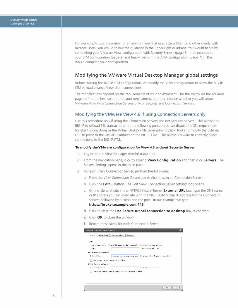
b. Click the Edit... button. The Edit View Connection Server settings box opens.
c. On the General tab, in the HTTP(S) Secure Tunnel External URL box, type the DNS name or IP address you will associate with the BIG-IP LTM virtual IP address for the Connection servers, followed by a colon and the port. In our example we type: https://broker.example.com:443
d. Click to clear the Use Secure tunnel connection to desktop box, if checked.
e. Click OK to close the window
f. Repeat these steps for each Connection Server.

DEPLOYMENT GUIDE VMware View 4.6
6
Special note about PC over IPBeginning with VMware View 4, VMware supports PC over IP (PCoIP) as a display protocol. PCoIP is an application encrypted UDP protocol, so the BIG-IP system cannot offload encryption for it.
If you want to use PCoIP, we recommend you enable direct connections to the desktop using PCoIP. This means the View client connects to the View Manager server for authentication, authorization and obtaining desktop information. Then, when the users choose a desktop to connect to, the view client opens a new connection directly to the desktop, bypassing the BIG-IP and connection manager. If you are deploying an environment with mixed display protocols, we recommend enabling direct access for all protocols. Refer to the VMware View administrators guide for details.
This does not apply if you are using VMware Security Server.
Modifying VMware View 4.6 if using Security Servers and Connection Servers
Use this procedure if using Security Servers and Connections Servers. In this scenario, the BIG-IP is used to load balance Security Servers and to act as a gateway for PCoIP connections. This procedure allows PCoIP servers to be moved off the DMZ if desired.
To modify the VMware configuration for View 4.6 using Security Server
1. Log on to the View Manager Administrator tool.
2. From the navigation pane, click to expand View Configuration and then click Servers. The Servers Settings opens in the main pane.
3. For each View Connection Server, perform the following:
a. In the main pane, from the View Connection Servers section, click to select a Connection Server.
b. Click the Edit... button. The Edit View Connection Server settings box opens.
c. On the General tab, in the HTTP(S) Secure Tunnel External URL box, type the DNS name or IP address you will associate with the BIG-IP LTM virtual IP address for the Security Server, followed by a colon and the port. In our example we type: https://security.example.com:443
d. Click OK to close the window
e. Repeat these steps for each Connection Server.
4. For each View Security Server, perform the following:
a. From the View Security Servers section, click to select a Security Server.
b. Click the Edit... button. The Edit Security Server box opens.
c. In the HTTP(S) Secure Tunnel External URL box, type the DNS name or IP address you will associate with the BIG-IP LTM virtual IP address for the Security Servers, followed by a colon and the port. In our example, we type: https://security.example.com:443.
d. If you are using PCoIP, in the PCoIP External URL box, type the appropriate URL followed by a colon and the port. In our example, we use security.example.com:4172.
e. Click OK to close the window
f. Repeat these steps for each Security Server.

DEPLOYMENT GUIDE VMware View 4.6
7
Configuring the BIG-IP LTM for View 4.6 for the Connection Servers
Use this section for configuring the LTM for Connection Servers only. For Security Servers, see page 9. This table contains a list of BIG-IP LTM configuration objects along with any non-default settings you should configure as a part of this deployment. Unless otherwise specified, settings not mentioned in the table can be configured as applicable for your configuration. For specific instructions on configuring individual objects, see the online help or product manuals.
BIG-IP LTM Object Non-default settings/Notes
Health Monitor (Main tab-->Local Traffic -->Monitors)
Name Type a unique name
Type HTTP
Interval 30 (recommended)
Timeout 91 (recommended)
Send String GET / \r\n\r\n
Receive String view1
Pool (Main tab-->Local Traffic -->Pools)
Name Type a unique name
Health Monitor Select the monitor you created above
Load Balancing Method Choose your preferred load balancing method
Address Type the IP Address of the Connection Server nodes
Service Port 80 (repeat Address and Service Port for all nodes)
iRule See Creating the Persistence iRule on page 8
Profiles (Main tab-->Local Traffic -->Profiles)
HTTP (Profiles-->Services)
Name Type a unique name
Parent Profile http-lan-optimized-caching
TCP WAN (Profiles-->Protocol)
Name Type a unique name
Parent Profile tcp-wan-optimized
TCP LAN (Profiles-->Protocol)
Name Type a unique name
Parent Profile tcp-lan-optimized
Persistence (Profiles-->Persistence)
Name Type a unique name
Persistence Type Universal
iRule Select the iRule you created above
OneConnect (Profiles-->Other)
Name Type a unique name
Parent Profile oneconnect
Client SSL (Profiles-->SSL)
Name Type a unique name
Parent Profile clientssl
Certificate and Key Select your Certificate and key
Virtual Server (Main tab-->Local Traffic -->Virtual Servers)
Name Type a unique name.
Address Type the IP Address for the virtual server
Service Port 443
Protocol Profile (client)1 Select the WAN optimized TCP profile you created above
Protocol Profile (server)1 Select the LAN optimized TCP profile you created above
OneConnect Profile Select the OneConnect profile you created above
HTTP Profile Select the HTTP profile you created above
SSL Profile (client) Select the Client SSL profile you created above
SNAT Pool 2 Automap (optional; see footnote 2)
Default Pool Select the pool you created above
Persistence Profile Select the Universal Persistence profile you created above
 Important
The Connection Server
configuration is only
necessary if you are not
using Security Servers.
If you are using Security
Servers, go to page 9.
1 The word “view” appears in the default View installation. If you have a custom page, choose a text string from that page here 2 You must select Advanced from the Configuration list for these options to appear 3 If your Connection Servers do not have a route back for clients through the BIG-IP, i.e. if they do not use the BIG-IP as the
default gateway, enable SNAT Automap to translate the client’s source address to an address on the BIG-IP. The Connection Servers use this new source address as the destination address for client traffic originating through the BIG-IP. If your View deployment is exceptionally large, specifically more than 64,000 simultaneous connections, a SNAT Pool must be configured. See the BIG-IP documentation on configuring SNAT Pools.

DEPLOYMENT GUIDE VMware View 4.6
8
Creating the Universal Inspection Engine persistence iRule
Using the following iRule, the BIG-IP LTM is able to direct traffic with greater precision resulting in a more uniform load distribution on the Connection Servers. Using the Universal Inspection Engine (UIE), the iRule looks for session information so that the BIG-IP LTM can persist the connections to the proper nodes. The View clients first use the session information in a cookie, and then use it as an URI argument when the tunnel is opened. The first response from the server contains a JSESSIONID cookie. The iRule enters that session ID into the connection table and upon further client requests looks for the information in a cookie or in the URI.
For the following iRule to function correctly, you must be using the BIG-IP LTM system to offload SSL transactions from the View implementation, as described in this deployment guide. You should only use this iRule if you are not using the Security Server.
To create the persistence iRule
1. On the Main tab, expand Local Traffic, and then click iRules.
2. Click the Create button.
3. In the Name box, type a name for this rule. In our example, we type view-jsessionid.
4. In the Definition box, copy and paste the following iRule, omitting the line numbers.
5. Click the Finished button.
This completes the Connection Server LTM configuration, if you are using Security Server, continue to the following section.
Important
123456789101112131415161718192021222324
when HTTP_REQUEST { if { [HTTP::cookie exists "JSESSIONID"] } { # log local0. "Client [IP::client_addr] sent cookie [HTTP::cookie "JSESSIONID"]" set jsess_id [string range [HTTP::cookie "JSESSIONID"] 0 31] persist uie $jsess_id # log local0. "uie persist $jsess_id" } else { # log local0. "no JSESSIONID cookie, looking for tunnel ID" set jsess [findstr [HTTP::uri] "tunnel?" 7] if { $jsess != "" } { # log local0. "uie persist for tunnel $jsess" persist uie $jsess } }}when HTTP_RESPONSE { if { [HTTP::cookie exists "JSESSIONID"] } { persist add uie [HTTP::cookie "JSESSIONID"] # log local0. "persist add uie [HTTP::cookie "JSESSIONID”] server: [IP::server_addr] client: [IP::client_addr]" }}# when LB_SELECTED {# log local0. "Member [LB::server addr]"# }

DEPLOYMENT GUIDE VMware View 4.6
9
Configuration for View 4.6 with Security Server
This section contains LTM configuration guidance if you are using the Security Servers. If you are not using Security Servers, do not use this section, and continue with Configuring the BIG-IP APM for VMware View 4.6 on page 11.
Configuration for Security Server requires three virtual servers. The following tables contain a list of BIG-IP LTM configuration objects along with any non-default settings you should configure as a part of this deployment. Unless otherwise specified, settings not mentioned in the table can be configured as applicable for your configuration. For specific instructions on configuring individual objects, see the online help or product documentation.
See Appendix B on page 19 for an alternate way to configure the health monitors and pools.
BIG-IP LTM Object Non-default settings/Notes
Health Monitors (Main tab-->Local Traffic -->Monitors)
TCP
Name Type a unique name
Type TCP
Alias Service Port1 4172
HTTPS
Name Type a unique name
Type HTTPS
Alias Service Port1 443
Send String GET / \r\n\r\n
Receive String view2
UDP
Name Type a unique name
Type UDP
Alias Service Port1 4172
Pool (Main tab-->Local Traffic -->Pools)
Name Type a unique name
Health Monitors Select each of the monitors you created above
Availability Requirement1 All
Load Balancing Method Least Connections (Node)
Address Type the IP Address of the Security Server nodes
Service Port 0 (repeat Address and Service Port for all nodes)
Profiles (Main tab-->Local Traffic -->Profiles)
HTTP (Profiles-->Services)
Name Type a unique name
Parent Profile http
TCP WAN (Profiles-->Protocol)
Name Type a unique name
Parent Profile tcp-wan-optimized
TCP LAN (Profiles-->Protocol)
Name Type a unique name
Parent Profile tcp-lan-optimized
UDP (Profiles-->Protocol)
Name Type a unique name
Parent Profile UDP
Persistence (Profiles-->Persistence)
Name Type a unique name
Persistence Type Source Address Affinity
Match Across Virtual Servers Click a check in the box
Client SSL (Profiles-->SSL)
Name Type a unique name
Parent Profile clientssl
Certificate Select the Certificate you imported
Key Select the Key you imported
Server SSL (Profiles-->SSL)
Name Type a unique name
Parent Profile serverssl
Certificate and key Default, or imported certificate &key
1 You must select Advanced from the Configuration list for these options to appear 2 The word “view” appears in the default View installation. If you have a custom page, choose a text string from that page here
LTip
Critical
Critical Note: This table continues with the virtual server configuration on the following page

DEPLOYMENT GUIDE VMware View 4.6
10
BIG-IP LTM Object Non-default settings/Notes
Virtual Servers (Main tab-->Local Traffic -->Virtual Servers)
TCP
Name Type a unique name.
Address Type the IP Address for the virtual server
Service Port 4172
Protocol Profile (client)1 Select the WAN optimized TCP profile you created above
Protocol Profile (server)1 Select the LAN optimized TCP profile you created above
SNAT Pool 2 Automap (optional; see footnote 2)
Default Pool Select the pool you created above
Persistence Profile Select the Source Address Persistence profile you created above
HTTPS
Name Type a unique name.
Address Type the IP Address for the virtual server
Service Port 443
Protocol Profile (client)1 Select the WAN optimized TCP profile you created above
Protocol Profile (server)1 Select the LAN optimized TCP profile you created above
HTTP Profile Select the HTTP profile you created above
SSL Profile (client) Select the Client SSL profile you created above
SSL Profile (server) Select the Server SSL profile you created above
SNAT Pool 2 Automap (optional; see footnote 2)
Default Pool Select the pool you created above
Persistence Profile Select the Source Address Persistence profile you created above
UDP
Name Type a unique name.
Address Type the IP Address for the virtual server
Service Port 4172
Protocol UDP
Protocol Profile (client)1 Select the UDP profile you created above
SNAT Pool 2 Automap (optional; see footnote 2)
Default Pool Select the pool you created above
Persistence Profile Select the Source Address Persistence profile you created above
1 You must select Advanced from the Configuration list for these options to appear2 If your Security Servers do not have a route back for clients through the BIG-IP, i.e. if they do not use the BIG-IP as the default
gateway, enable SNAT Automap to translate the client’s source address to an address. The Security Servers will use this new
source address as the destination address for client traffic originating through the BIG-IP.
If your View deployment is exceptionally large, specifically more than 64,000 simultaneous connections, a SNAT Pool must be
configured. See the BIG-IP documentation on configuring SNAT Pools.
This completes the Security Server configuration. See the Appendix on page 19 for an alternate way to configure the health monitors and pools, or continue with the BIG-IP APM configuration on the following page.

DEPLOYMENT GUIDE VMware View 4.6
11
Configuring the BIG-IP APM for VMware View 4.6
In this section, we configure the BIG-IP Access Policy Manager (APM) for the VMware View Security or Connection Servers. APM may be used with either of the configuration modes described in the LTM portion of this guide.
This table contains any non-default setting you should configure as a part of this deployment. Unless otherwise specified, settings not mentioned in the table can be configured as applicable for your configuration.
For specific instructions on configuring individual objects, see the online help or product documentation.
Using the Network Access Setup Wizard
This table contains guidance on using the Network Access Setup Wizard for Remote Access.
To start the wizard, from the Main tab of the Configuration utility, click Templates and Wizards, and then click Device Wizards. In the Wizard section, click the Network Access Setup Wizard for Remote Access option button.
Wizard section Non-default settings/Notes
Basic Properties
Policy Name Type a unique name. We use view-apm-access
Default Language Select a language. We leave the default, en
Client Side Checks Leave the box checked.
Authentication Domain Name Click the Active Directory option button
AAA Server NameType the FQDN of your Active Directory implementation If necessary, type the Domain Controller and Admin credentials
Lease Pool
TypeClick the option button for a single IP address or an address range. We click IP Address Range
Address(es)
Type an IP address. If you selected a range, type both the start and end IP addresses. We recommend using enough addresses for the highest number of concurrent network access connections you anticipate. We use 192.0.2.1 and 192.0.2.254
Network Access
Compression Click GZIP1 (strongly recommended)
Traffic Options
Click the option button for Forcing all traffic through the tunnel or split tunneling. If you chose split tunneling, configure the split tunneling options as applicable for your configuration. We click Force all traffic through tunnel
DTLS2 Check the box to enable DTLS 2. If neccesary, update the port
DNS Hosts Primary Name ServerType the IP address of the Active Directory Server in the network; all other settings optional
Virtual Server
IP addressType the IP address to use for this virtual server. This is the address used for Network Access connectivity.
Redirect ServerLeave this box checked. This creates a virtual server that only redirects requests from HTTP to HTTPS.
1 If Datagram TLS (DTLS) is configured (UDP based communication between client and Remote Access Server) GZIP compression is automatically disabled. DTLS and GZIP compression are incompatible with one another. If you enable GZIP compression it will be used for TCP connections. DTLS clients will use compression for network access tunnels.
2 DTLS uses UDP port 4433 by default. Arrange to open this port on firewalls as needed. If clients cannot connect with DTLS, they fall back to TCP based SSL. We recommend using the DTLS protocol for optimum performance.

DEPLOYMENT GUIDE VMware View 4.6
12
Configuring additional BIG-IP APM objects
In this section, we configure the BIG-IP APM for objects that were not created by the wizard. This table contains any non-default setting you should configure as a part of this deployment. Unless otherwise specified, settings not mentioned in the table can be configured as applicable for your configuration.
For specific instructions on configuring individual objects, see the online help or product documentation.
BIG-IP Object Non-default settings/Notes
Web Application (Main tab-->Access Policy -->Web Applications)
Name Specify a unique name. We use DownloadViewClient
PatchingType: MInimal Patching. Click Scheme Patching box. Click Create. Stay on Web Application page to add Resource item.
- Resource Items (Web Application page-->Resource Items section-->Add)
Destination Click IP Address option button. Type the IP address of the LTM virtual server you created for the Connection Servers.
Port Type 443
Scheme Select HTTPS
Paths Type /*
Compression Select GZIP
All other settings at the defaults
Webtop (Main tab-->Access Policy -->Webtops)
Name Specify a unique name. We use view-webtop
Type Web Applications
Web Application Start URI
Type the IP address or FQDN of the LTM virtual server you created for the Connection Servers.
Profiles (Main tab-->Local Traffic -->Profiles)
Rewrite (Profiles-->Services)
Name Type a unique name
Client Caching Type Must be set to CSS and Java Script
HTTP (Profiles-->Services)
Name Type a unique name
Parent Profilehttp (must not have compression or caching enabled)
TCP WAN (Profiles-->Protocol)
Name Type a unique name
Parent Profile tcp-wan-optimized
TCP LAN (Profiles-->Protocol)
Name Type a unique name
Parent Profile tcp-wan-optimized
Client SSL (Profiles-->SSL)
Name Type a unique name
Parent Profile clientssl
Certificate Select the Certificate you imported
Key Select the associated Key you imported
Server SSL (see note) (Profiles-->SSL)
Name Type a unique name
Parent Profile serverssl
Modify Virtual Server (Main tab-->Local Traffic -->Virtual Servers)
Virtual Server Click the name of the APM virtual server created by the wizard
Protocol Profile (client) Select the WAN optimized TCP profile you created above
Protocol Profile (server) Select the LAN optimized TCP profile you created above
HTTP Profile Select the HTTP profile you created above
SSL Profile (Client) Select the Client SSL profile you created above
SSL Profile (Server) Select the Server SSL profile you created above (see note)
Rewrite Profile Select the Rewrite profile you created above
Access Policy (Main tab-->Access Policy -->Access Profiles)
EditEdit the Access Profile created by the wizard using the Visual Policy Editor. See Configuring the Access Policy on page 13 for instructions.
 Note: If your download source is an
SSL protected server, a Server
SSL profile is required. Your
download source was defined
in both the Web Application
and Webtop you created. For
example, if you are pointing
to the Connection Broker LTM
virtual server as recommended
in this guide, you will need this
Server SSL profile.
If you are pointing directly at a
Connection Broker listening on
port 80, this Server SSL profile is
not required.

DEPLOYMENT GUIDE VMware View 4.6
13
Configuring the Access Policy
In the following procedure, we show you how to configure edit the Access Policy on the APM using the Visual Policy Editor (VPE). The VPE is a powerful visual scripting language that offers virtually unlimited options in configuring an Access Policy. The Policy shown in the following procedure is just an example, you can use this Access Policy or create one of your own.
To configure the Access Policy
1. On the Main tab, expand Access Policy, and then click Access Profiles.
2. Locate the Access Profile created by the wizard, and then, in the Access Policy column, click Edit. The VPE opens in a new window.
3. Click the + symbol between Start and Antivirus Check. A box opens with options for different actions.
4. Click the Client OS option button, and then the Add Item button at the bottom.
a. In the Name field, you can optionally type a new name.
b. Click the Branch Rules tab.
c. In the Windows 7 row, change the name to Windows 7, Vista and XP.
d. Click the change link.
e. Under OR, click the Add Expression button. You must click the button under OR and not next to AND.
f. From the Agent Sel: list, select Client OS.
g. From the Client OS is list, select Windows Vista.
h. Click the Add Expression button.
i. Below Windows Vista and under OR, click the Add Expression button.
j. Repeat Steps f - h, but in step g, select Windows XP.
k. Click Finished. You return to the Branch rules tab.
l. From the Windows Vista and Windows XP rows, click the delete button (x).
m. Click the Save button
5. Click the Add New Macro button. The new macro box opens.
a. In the Name box, type a name for this macro. In our example, we type UnsupportedOSMessage
b. Click the Save button. The Macro appears under the Access Policy.
c. Click the Expand (+) button next to UnsupportedOSMessage.
d. Click the + symbol between In and Out. A box opens with options for different actions.
e. Click the Message box option button, and then click Add Item.
f. In the Name box, type a unique name for this box. In our example, we type serviceNotAvailableforThisOS.
g. In the Message box, type the message you want users to see. In our example, we type This service is available for Windows 7, Vista or XP clients only.
h. You can optionally modify the Link text. Clicking the link sends the user to the next object in the path, Deny in our example.
i. Click the Save button. The macro is now ready to use in the following step.
Important

DEPLOYMENT GUIDE VMware View 4.6
14
6. Click the + symbol between Windows 2000 and Deny. A box opens with options for different actions.
7. In the Macrocalls section, click the option button for the macro you just created, and then click the Add Item button. In our example, we click UnsupportedOSMessage.
8. Repeat steps 6 and 7 for each of the operating systems you want to deny.
9. On the Fallback path between Antivirus check and Deny, click the + symbol.
10. In the General Purpose section, click the click the Message box option button, and then click Add Item.
a. In the Name box, type a unique name for this box. In our example, we type antiVirusNotFound.
b. In the Message box, type the message you want users to see. In our example, we type You do not have the proper AntiVirus software installed on your machine. Please install or update your Antivirus software.
c. You can optionally modify the Link text. Clicking the link sends the user to the next object in the path, Deny in our example.
d. Click the Save button.
11. On the Successful path between AD Auth and Resource Assign, click the + symbol.
12. In the Client Side Check section, click the Windows File Check option button, and then click the Add Item button. The Windows File Checker page opens. Complete the following:
a. In the Name box, you can optionally type a new name. In our example, we type checkForViewClient.
b. Click the Add new entry button.
c. In the FileName box, type the path to the View client as appropriate for your View deployment. In our example, we type:
c:\\Program\ Files\\VMware\\VMware\ View\\Client\\bin\\wswc.exe
The double backslashes are required for the inspector to check for the file. If your View client is installed in a custom location be sure to set the correct path to the executable.
d. Leave the rest of the settings at their default levels.
e. Click the Save button.
13. On the Fallback path between Resource Assign and Allow, click the + symbol.
14. In the General Purpose section, click the Variable Assign option button, and then click the Add Item button. The Resource Assignment page opens. Complete the following:
a. In the Name box, you can optionally type a new name. In our example, we type configureViewSSO.
b. Click the Add new entry button.
c. Click the change button.
d. From the list on the left, select Configuration Variable and then select Secure from the adjacent list.
e. From the Property list, select application launch.
f. In the Custom Expression box on the right, use the following syntax for the expression, replacing the red text with information from your implementation (see note following).
The second line of following code must be entered as a single line. If you copy and paste from this document, you will likely pick up unnecessary spaces or line breaks that will cause a syntax error in the code. We present the code below for your information; we strongly
Note
Critical

DEPLOYMENT GUIDE VMware View 4.6
15
recommend you copy and paste the code from the following text file: http://www.f5.com/solutions/resources/deployment-guides/files/vmware-view-vpe-expression.txt. And then carefully replace the values in red below with values from your implementation.
expr {"<application_launch><item><path>C:\\Program\ Files\\VMware\\VMware\ View\\Client\\bin\\wswc.exe</path><parameter>-username [mcget {session.logon.last.username}] -password [mcget -secure {session.logon.last.password}] -domainName BD -serverURL https://broker.example.com:443</parameter><os_type>WINDOWS</os_type></item></application_launch>"}
If your View client is installed in a custom location, be sure to set the correct path to the executable. Our domainName is BD; insert the correct name of your domain. The serverURL parameter indicates where clients should connect to for accessing the View Connection Servers (the BIG-IP LTM virtual server); replace the value of this parameter with the Connection Server virtual server IP address or Domain Name. Additional parameters are available in the client and can be set here. Refer to VMware View client documentation for more information.
g. Click the Finished button.
h. On the Variable Assign page, click the Save button.
15. On the Fallback path between checkForViewClient and Deny, click the + symbol.
16. In the General Purpose section, click the Decision Box option button, and then click the Add Item button. The Decision box page opens. Complete the following:
a. In the Name box, you can type a name. In our example, we type askUserDownload.
b. In the Message box, type a message for users to see when the View client is not found. In our example, we type View client not found.
c. In the Option 1 box, type something similar to Download client now.
d. In the Option 2 box, type something similar to Disconnect.
e. Click the Save button.
17. On the Option 1 path between askUserDownload and Deny, click the + symbol.
18. In the General Purpose section, click the Resource Assign option button, and then click Add Item. The Resource Assign page opens. Complete the following:
a. In the Name box, you can type a new name. In our example, we type downloadViewClient.
b. Click the Add new entry button.
c. Click the Add/Delete Web Application Resources link.
d. Check the box for the Web Application you created in the table above. In our example, we check the DownloadViewClient box. Click Update.
e. Click the Set Webtop link.
f. Click the option button for the Webtop you created in the table above. In our example, we click the view-webtop button. Click Update
g. Click the Save button.
19. On the Fallback path after downloadViewClient, click the Deny box.
20. Under Select Ending, click the Allow button, and then click Save.
21. Click the yellow Apply Access Policy link in the upper left part of the window. You must apply an access policy before it takes effect.
Note

DEPLOYMENT GUIDE VMware View 4.6
16
Optional: Configuring the BIG-IP APM for Client Traffic Optimization
The F5 Edge Client has the ability to prioritize client traffic exiting the tunnel. Priority can be given to VMware View traffic by configuring Traffic Client Controls on the BIG-IP APM. This allows desktop traffic to be favored if bandwidth becomes limited.
To configure Traffic Client controls:
1. On the Main tab, expand Access Policy, and then click Network Access.
2. From the Menu bar, select Client Traffic Control, and then click Client Rate Class List.
3. Click the Create button.
4. In the Name box, type a name. In our example, we type VMware-View-UDP.
5. In the Base Rate box, type 200, and then select Kbps from the list. The VMware View reference architecture and our testing shows a base rate of 200 Kbps is good starting point for traffic (VMware View Reference Architecture) .
6. Leave all other settings at default
7. Click Finished. This reserves a set bandwidth for View and allows for bursting.
8. From the Menu bar, select Client Traffic Control, and then click Client Traffic Classifier List.
9. Click the Create button.
10. In the Name box, type a name. In our example, we type VMware-View-UDP.
11. Click the Create button.
12. From the Client Traffic Classifiers table, click the name of the classifier you just created. In our example, we click VMware-View-UDP.
13. In the Rules for Virtual Network Access Interface section, click the Add button.
14. Select Advanced from the list.
15. From the Client Rate Class list, select the name of the Rate Class you created.
16. From the Protocol list, select UDP.
17. Leave the Destination Address set to Any.
18. In the Destination Port box, type 4172.
19. Leave the Source Address set to Any.
20. In the Source Port box, type 4172.
21. Click the Finished button.
22. On the Main tab, expand Access Policy, and then click Network Access.
23. From the Network Access List, click the name Network Access object with the name you gave your policy in the first step of the Network Access wizard followed by _na_res. In our example, we click view-apm-access_na_res.
24. In the Client Access Settings section, select Advanced from the list.
25. From the Client Traffic Classifier list, select the name of the classifier you created above. In our example, we select VMware-View-UDP.
26. Click Update.

DEPLOYMENT GUIDE VMware View 4.6
17
Next Steps
If you have followed the guidance in this document, the BIG-IP is configured for VMware View and is ready for your users. You should have also made the configuration changes to VMware View to match the deployment scenario for your users (VMware Connection Servers alone, or with Security Server).
In this section, we show you how to verify your environment is functioning properly.
If you have deployed BIG-IP APM, we recommend testing APM as well as LTM. First use the procedure for BIG-IP APM, and then continue to the steps for testing BIG-IP LTM.
To test BIG-IP APM/LTM with VMware View
1. Launch the BIG-IP Edge Client and connect to the Virtual Server you configured for access. This is not the virtual IP address used for load balancing VMware View; it is the remote access virtual server configured in the APM section of the guide.
2. Enter your user credentials, which should be a user in the View Active Directory environment. For testing, it is useful to test both an allowed user present in AD, and a non-configured or non-allowed user to ensure that authentication is working as you configured it.
3. Once you are logged in, if your machine does not have a VMware View Client installed (on a Windows environment), the BIG-IP Edge client automatically prompts you to download it. If the View client is installed, it automatically launches and you are automatically logged in. If your Single-Sign on is setup properly, you should not see any authentication prompts
4. Choose the desktop to which your user is entitled and test the functionality of the desktop.
To test BIG-IP LTM with VMware View
1. Launch the VMware View Client and enter the virtual server address of the LTM used to load balance the View environment. If you have configured VMware View Security Server, this is the virtual address associated with the Security Servers. If you have only used the Connection Servers, then use the virtual address associated with the Connection servers.
2. Type your user name and password when prompted.
3. Perform tests on your entitled desktop as you would normally.
Viewing statistics
You can easily view a number of different statistics on the BIG-IP system related to the View configuration objects you created.
To view LTM statisticsOn the Main tab, expand Overview, and then click Statistics. From the Statistics Type menu, you can select Virtual Servers to see statistics related to the virtual servers. You can also choose Pools or Nodes to get a closer look at the traffic.
To see Networking statistics in a graphical format, expand Overview and then click Dashboard.
To view APM statisticsOn the Main tab, expand Access Policy, and then click Dashboard. You can monitor the user session from the Dashboard. You can also view custom reports by clicking Reports under Access Policy.
For more information on viewing statistics on the BIG-IP system, see the online help or product documentation.
Note

DEPLOYMENT GUIDE VMware View 4.6
18
Appendix A: VMware View Support with BIG-IP for iPad
In this Appendix, we provide a sample client application configuration for Apple® iPad™ devices. VMware View allows users access to applications on their mobile devices. For each device, users install an application that then allows access to installed applications in your View environment.
If you are using the BIG-IP APM, you have to configure the Edge Client to connect to BIG-IP APM. http://support.f5.com/content/kb/en-us/products/big-ip_apm/manuals/product/apm_ios_client_app/_jcr_content/pdfAttach/download/file.res/m_apm_ios_client_app.pdf
Configuring the iPad for VMware View support with LTM
Use the following procedure to configure the Apple iPad for VMware View support.
To configure the iPad for VMware View Support
1. Download and install the free VMware View application from the Apple Store for your iPad.
2. Launch the application by pressing the VMware View icon.
3. In the upper right corner, press the + sign. A dialog box opens.
4. In the box, type the BIG-IP virtual server host name or IP address of either the Security Server virtual server (if using Security Server) or the Connection Server virtual server (if not using Security Server).

DEPLOYMENT GUIDE VMware View 4.6
19
5. Press Connect.
6. Select the appropriate Desktop View to enter the desktop.

DEPLOYMENT GUIDE VMware View 4.6
20
Appendix B: Alternate configuration method for more granular monitoring of Security Servers
While the configuration in this appendix is more complex, it enables per node statistics within BIG-IP. With the primary configuration mode for Security Servers, configuration is less complex but only per virtual statistics are visible. If per node statistics are critical to your environment, use the following guidance to configure the health monitors and pools.
BIG-IP LTM Object Non-default settings/Notes
Health Monitors (Main tab-->Local Traffic -->Monitors)
TCPName Type a unique name
Type TCP
HTTPS
Name Type a unique name
Type HTTPS
Send String GET / \r\n\r\n
Receive String view1
UDPName Type a unique name
Type UDP
Pool (Main tab-->Local Traffic -->Pools)
TCP
Name Type a unique name
Health Monitors Select the TCP monitor you created
Load Balancing Method Least Connections (Node)
Address Type the IP Address of the Security Server nodes.
Service Port 4172 (repeat Address and Port for all nodes)
HTTPS
Name Type a unique name
Health Monitors Select the HTTPS monitor you created
Load Balancing Method Least Connections (Node)
Address Type the IP Address of the Security Server nodes.
Service Port 443 (repeat Address and Port for all nodes)
UDP
Name Type a unique name
Health Monitors Select the UDP monitor you created
Load Balancing Method Least Connections (Node)
Address Type the IP Address of the Security Server nodes.
Service Port 4172 (repeat Address and Port for all nodes)
1 The word “view” appears in the default View installation. If you have a custom page, choose a text string from that page here
Use the table on page 9 for configuring the profiles and virtual servers. With the following two exceptions.
h Persistence Profile For the Source Address Affinity persistence profile, click a check in the Match Across Services box. Do not check the Match Across Virtual Servers box as stated in the table.
h Virtual Servers For each virtual server, select the appropriate pool you created in this section. So for the TCP virtual server on port 4172, you select the TCP pool you created in this section. For the HTTPS virtual server on port 443, you select the HTTPS pool you created in this sec-tion. For the UDP virtual server, you create the UDP pool you created in this section.
Critical
DEPLOYMENT GUIDE VMware View 4.6
21
© 2011 F5 Networks, Inc. All rights reserved. F5, F5 Networks, the F5 logo, BIG-IP, FirePass, and iControl are trademarks or registered trademarks of F5 Networks, Inc. in the U.S. and in certain other countries.
F5 Networks, Inc.Corporate Headquarters
F5 Networks, Inc. 401 Elliott Avenue West, Seattle, WA 98119 888-882-4447 www.f5.com
F5 NetworksAsia-Pacific
F5 Networks Ltd.Europe/Middle-East/Africa
F5 NetworksJapan K.K.
Document Revision History
Version Description
1.0 New guide
1.1 Modified the Configuration Matrix on page 4 to remove the specific references to the Wyse™ Zero Client, as there are other vendors offering Zero Clients.
1.2 Added guidance to the BIG-IP LTM virtual server configuration for using SNAT Automap.
1.3 Added a section on configuring a Webtop for BIG-IP APM. Added a Server SSL profile to the APM virtual server.
1.4 Added a Send String (GET / \r\n\r\n) and Receive String (view) to the HTTPS monitor for the Connection and Security Servers.
1.5 Removed the HTTP and Server SSL profiles from the Security Server TCP virtual server Modified the Variable Assign APM object from Unsecure to Secure (step 14d on page 14.


![INDEX [] LG-1550 LIEBHERR LTM 1500 LIEBHERR LTM-1400 LIEBHERR LTM-1225 LIEBHERR LTM-1220 LIEBHERR ... Cranes_over100tons.pdf](https://img.pdfslide.us/doc/110x75/5b07232e7f8b9ae9628e08fa/index-lg-1550-liebherr-ltm-1500-liebherr-ltm-1400-liebherr-ltm-1225-liebherr.jpg)