Embed Size (px)
Citation preview
Deployable Optics for Earth Observing Lidar InstrumentsL.D. Peterson and J.D. Hinkle
University of ColoradoCenter for Aerospace Structures
Department of Aerospace Engineering SciencesBoulder, Colorado 80309-0429
S. IsmailNASA Langley Research Center
Atmospheric SciencesMS 401A
Hampton, Virginia 23681
Abstract-This paper presents an overview of the DeployableOptics Modeling Experiments (DOME), Advanced ComponentTechnology (ACT) project. DOME is developing and advancingto flight readiness precision deployable optics technology forspace-based lidar instruments. The overall objective is to enablelow cost, passively deployed mirrors for UV-DIAL instrumentsfrom 2 meters to 10 meters in diameter. The key technologiesinclude high precision deployment mechanisms with submicronlevel stability and precision. The project includes experimentalverification of models that predict the on-orbit precision andstability of a deployed mirror petal. This includes verification ofmodels of the nonlinear microdynamic stability, deploymentrepeatability, and mechanical hysteresis. Even though thetechnology is being tested at UV wavelengths for potential UV-DIAL applications, it has wide ranging applications for UV,visible, near- and mid-IR lidar systems in DIAL as well otherlidar systems for atmospheric species, aerosols, clouds, anddirect detection wind systems. DOME technology hasapplication to space-based astronomical instruments as well.
I. INTRODUCTION
Precision deployable reflectors for space-based telescopeswill be a key space engineering challenge for the next severaldecades. Such deployable reflectors are envisioned for avariety of missions, from Earth observation to spaceastronomy. Whether they operate in IR, visible or UV, allthese applications share similar requirements for extremelystable and accurate deployed configurations.[1-3]
The engineering challenge is to achieve the necessarystability and accuracy for lowest overall system cost. Perhapsthe most significant cost savings is realized by deploying thetelescope rather than launching it in its final configuration (aswas the Hubble). Most large space structures are not massconstrained but volume constrained. Deployment makes thebest use of the available launch vehicle payload capacity. [4]
Deployment, however, brings with it many system leveltrades that make the cost prohibitive if not properlyconsidered. Deployment implies the structure is articulated insome fashion, having mechanisms that impart degrees offreedom and allow motion. The parts of the structure must
move through many meters of motion, ending up within verytight tolerances, often less than a few microns of the intendedposition. Once deployed, the structure must hold its position,that is “remain stiff and stable,” within the necessarytolerance even under on-orbit loads.[1] This is where thecritical trades interact.
The need for stiffness and stability once deployed can onlybe met by deployed structural “depth” that resistsdeformation. [5-7] In fact, the problem is not so much one ofunfolding the mirror of the telescope, for that is commonly anearly “two dimensional” kinematic problem. The majorproblem is deploying the deep structure that supports themirror. That is a three dimensional kinematic problem. Inother words, the stowed configuration must be expanded inall directions to achieve the final shape and function. Thismeans more articulation in the deployment, which furtherincreases complexity and risk.
In the case of deployed radio frequency (RF) reflectors, thestate of the art can deploy structures with perhaps part per1,000 or part per 10,000 overall stability and precision. [8] Inother words, a 10-meter diameter RF antenna might bedeployed and stabilized to within a fraction of a millimeter toa few millimeters. This is sufficient for RF applications. Butfor precisions necessary for optical instruments, pushingbeyond this limit requires special attention to the design ofthe mechanisms [9,10]. Phenomena arise below 100 micronsof resolution due to the small-scale friction and anelasticity inthe mechanisms and materials. This is known as“microdynamics” in the literature [11].
So a natural trade arises between the complexity of thedeployment, the deployed stiffness in the structure, thesophistication of the mechanisms, and the use of activeadjustment and control technologies. In a complex trade likethis, it is important to understand what defines the limits ofeach element in the trade, and then work to improve that limitas needed.
In the late 1990’s, NASA Langley Research Center(LaRC) and the University of Colorado (CU) initiated a
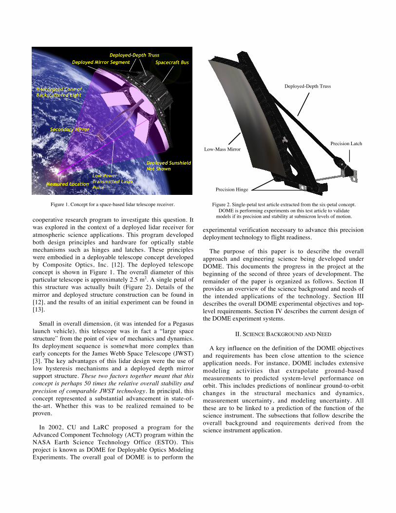
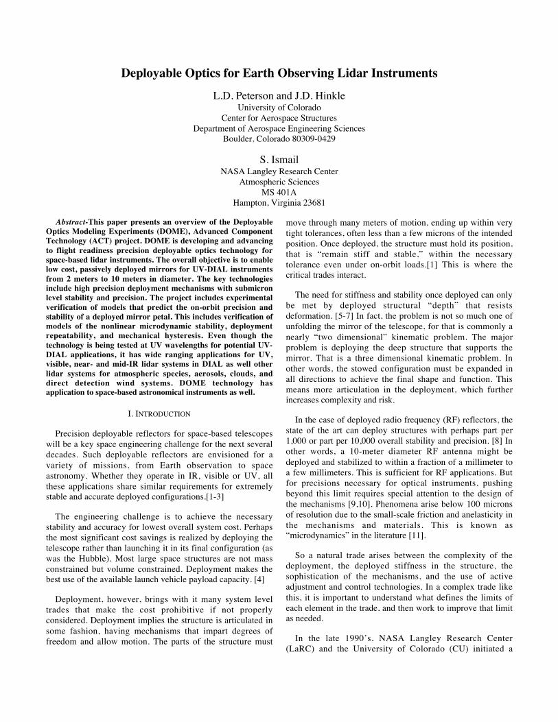
cooperative research program to investigate this question. Itwas explored in the context of a deployed lidar receiver foratmospheric science applications. This program developedboth design principles and hardware for optically stablemechanisms such as hinges and latches. These principleswere embodied in a deployable telescope concept developedby Composite Optics, Inc. [12]. The deployed telescopeconcept is shown in Figure 1. The overall diameter of thisparticular telescope is approximately 2.5 m2. A single petal ofthis structure was actually built (Figure 2). Details of themirror and deployed structure construction can be found in[12], and the results of an initial experiment can be found in[13].
Small in overall dimension, (it was intended for a Pegasuslaunch vehicle), this telescope was in fact a “large spacestructure” from the point of view of mechanics and dynamics.Its deployment sequence is somewhat more complex thanearly concepts for the James Webb Space Telescope (JWST)[3]. The key advantages of this lidar design were the use oflow hysteresis mechanisms and a deployed depth mirrorsupport structure. These two factors together meant that thisconcept is perhaps 50 times the relative overall stability andprecision of comparable JWST technology. In principal, thisconcept represented a substantial advancement in state-of-the-art. Whether this was to be realized remained to beproven.
In 2002, CU and LaRC proposed a program for theAdvanced Component Technology (ACT) program within theNASA Earth Science Technology Office (ESTO). Thisproject is known as DOME for Deployable Optics ModelingExperiments. The overall goal of DOME is to perform the
experimental verification necessary to advance this precisiondeployment technology to flight readiness.
The purpose of this paper is to describe the overallapproach and engineering science being developed underDOME. This documents the progress in the project at thebeginning of the second of three years of development. Theremainder of the paper is organized as follows. Section IIprovides an overview of the science background and needs ofthe intended applications of the technology. Section IIIdescribes the overall DOME experimental objectives and top-level requirements. Section IV describes the current design ofthe DOME experiment systems.
II. SCIENCE BACKGROUND AND NEED
A key influence on the definition of the DOME objectivesand requirements has been close attention to the scienceapplication needs. For instance, DOME includes extensivemodeling activities that extrapolate ground-basedmeasurements to predicted system-level performance onorbit. This includes predictions of nonlinear ground-to-orbitchanges in the structural mechanics and dynamics,measurement uncertainty, and modeling uncertainty. Allthese are to be linked to a prediction of the function of thescience instrument. The subsections that follow describe theoverall background and requirements derived from thescience instrument application.
Figure 1. Concept for a space-based lidar telescope receiver.
Deployed-Depth Truss
Precision Latch
Precision Hinge
Low-Mass Mirror
Figure 2. Single-petal test article extracted from the six-petal concept.DOME is performing experiments on this test article to validate
models if its precision and stability at submicron levels of motion.
A. Application to Space-Based Lidars
Ground and aircraft-based lidar (laser radar) systems havedemonstrated excellent capability for measuring atmosphericgas species, and aerosol and cloud distributions. Theadvantages of lidar measurements are their relatively highspatial resolution, high measurement specificity (avoidinginterference from other gases), lack of dependence onexternal light sources, and relatively simple inversionmethods compared to retrieval methods used in passiveremote sensing. Because of their capability to provide globalcoverage including over oceans and remote locations andtheir excellent spatial resolutions, NASA and other nationaland international agencies are attracted to the deployment ofthe lidars from space. However, long ranges from space tothe atmosphere require high power lasers and large collectionarea receivers to retain the signal-to-noise ratio and thequality of measurements provided by terrestrial lidar systems.
Demonstration of deployable telescope technology is oneof the key elements of lidar technology that is required for thedevelopment of future space-based lidar systems like the onefor the measurement of tropospheric ozone (O3) profiles[14,15]. Atmospheric O3 plays a key role in atmosphericchemistry, global warming, and in characterizing atmospherictransport/dynamics—the issues linked to our understandingof global atmospheric processes and their evolution. Globaltropospheric measurements of O3 from space are needed toanalyze, characterize, and assimilate into global predictionmodels for a better understanding of many of the atmosphericprocesses and for predicting future trends [16-18].
Strong scientific evidence is available to support thedevelopment of global tropospheric profiling system that isnot available at present. Recent investigations usingozonesonde measurements along the Asian Pacific Rim usinga global 3-D chemical transport model (GEOS-CHEM) atHarvard [19] have revealed a number of sources fortropospheric ozone including those due to biomass burning,anthropogenic pollution, stratospheric-tropospheric exchange,convection, and lightning. From these studies valuableinformation can be obtained about many atmosphericchemical processes. Differential Absorption Lidar (DIAL)systems have been widely used to study O3 and aerosols thatcan then be used to monitor and study many of theatmospheric processes. DIAL measurements of stratosphericO3 from ground stations [20-22] are routinely carried out tomonitor and study many stratospheric O3 processes. NASALangley’s airborne DIAL measurements of O3 [23] have beenused in field experiments over many region of the worldduring the past twenty years and demonstrated theirapplication to a broad range of process studies in theatmosphere. While these studies can be considered as the‘new frontier’ in the studies of the troposphere, there are atpresent, however, no global measurements of tropospheric O3that cover the entire globe. Passive remote sensing
measurements by Stratospheric Aerosol and Gas ExperimentII (SAGE II) and Microwave Limb Sounder (MLS) haveprovided excellent coverage of the stratosphere but onlylimited coverage in the troposphere. NASA’s GlobalTropospheric Experiments have shown that troposphericatmosphere is high structured and consists of narrow 1-3 kmsize layers [24-26]. Even planned future missions like Auraare expected to provide coarse resolution in the troposphere.
Development of large-area, lightweight, and compact (onlaunch) receiver system technologies would enable andenhance future space-based lidar missions. In particular theDIAL technique is well suited for measuring atmospheric O3,H2O, and CO2 profiles along with simultaneous aerosolmeasurements. Future space-based direct detection wind lidarsystems would also benefit from deployable telescopesystems. Lidar signals decrease as the square of the distanceto the target range and, consequently, space-basedmeasurements require a combination of high-energy lasers,large area receivers, and efficient optical detection systems.Deployable telescopes offer the largest enhancement factorsfor space based lidar signals. For example, a 2.5-m classdeployable telescope would provide an effective area of about3.5 m2, which is over five times that of a conventional 1-mdiameter telescope like that used in the LITE (Lidar-in-spaceTechnology Experiment) and planned missions like GLASS(Geoscience Lidar Altimeter System) and CALIPSO (Cloud-Aerosol Lidar and Infrared Pathfinder Satellite Observations),and about 35 times that of conventional airborne lidarsystems. Increased area receiver systems will also have otherbeneficial consequences: they increase lidar signals withoutincreases of laser power that would otherwise elevate lasereye safety issues particularly in the visible and near IRregions.
Development of deployable telescope technology for spaceapplication would have wide ranging lidar applications infuture lidar missions including those that will be follow on toCALIPSO and GLAS, and enable other DIAL missions likethose to measure global O3, H2O, and CO2 profiledistributions that are needed to study many climatic,chemical, and dynamical processes and for improvements inour understanding of the global water and carbon cycles.
B. System Requirements
The long ranges to the aerosol and/or molecular targets inthe atmosphere from the space vantage point are particularlyhard on active remote sensors such as lidar. This is becausethe laser energy incident on the target spreads out on its wayfrom the target back to the lidar. The magnitude of theenhancement of the signal for space-based lidar systems canbe appreciated by the fact that an enhancement of signal by afactor of 352 or 1225 is needed to replicate the performanceof airborne system operating from an altitude of 10 km andmaking measurements near the ground compared to making
the same measurements from a satellite at an altitude near350 km. Based upon the projected improvements in laser,detector, and optical throughput of future lidar systems andthe improvements due to the gain in the signal-to-noise due toincreased data averaging, a minimum diameter of asegmented telescope needed to enable a space mission wasidentified as 2.5 m [15]. Limited by the launch vehicles, suchlidar systems will have to resort to segmented, deployable,mirror panels to provide the required aperture area forcollection of return photons. The mirror panels must belightweight not just for meeting the launch constraints, butalso for avoiding the distortions of mirror panels and theirstructure after deployment under 0-g condition [12]. Thedeployable telescope systems will be applicable to a broadclass of direct detection lidar systems that will, in general, usesmall area single element solid-state detectors with diameterabout 0.5 mm. Consequently the maximum allowable spotsize at the focus has to be limited to a circle of diameter ofabout 0.5 mm.
III. EXPERIMENT OBJECTIVES AND REQUIREMENTS
The overall objective of the DOME project is to developand bring to flight readiness essential component technologyfor the deployment of Earth observing lidar telescopes. Thisconsists of three primary technical elements and objectivesdescribed in the next 3 subsections.
A. Precision Latching
Prior testing of the single-petal test article discoveredsignificant deployment precision error due to the design ofthe latch preloading mechanism. This was reported in [13].
The objective of this project element is to develop a newlatch that replaces the original latch. The new latch will havemicron level intrinsic repeatability, high stiffness and lowhysteresis. This is being done using the theory of mechanismdevelopment reported in [9] and [10], along with thedeployment repeatability reported in [27].
A key element in this part of the project is that theperformance of the latch be predictable by design analysis,not by trial and error. The models will be verified at both thecomponent level and the overall system level.
B. Sub-System Verification of Deployment Precision andStability
The objective of this element is to develop and implementan experiment that verifies the deployment precision andstability of the single-petal lidar test article in multiplegravity orientations.
Verification in multiple gravity orientations is a commontechnique applied to lower precision radio frequency
antennas. By showing that the deployment repeatability andstability satisfy required tolerances in orthogonal gravityorientations, it is expected this will bound the deployed shapeand stability in 0-g. This depends on the predictability of thedeployment mechanisms, and on the fidelity of the models.Such a measurement is also a minimum requirement todetermine whether further testing in 0-g would be requiredfor the technology. If successful, the techniques may alsoprovide validated verification methods for deployed opticalflight systems.
C. Theoretical Modeling
The objective of this project element is to develop atheoretical model, correlated with the above experiments,which can be used for specifying requirements and toleranceson a future flight lidar system. This includes linking themodel inputs to real flight conditions (including 0-g) andlinking the model outputs to the actual science instrumentperformance.
This modeling objective is essential to be able to trace theresults of the experiments to the intended application. Thekey challenge to this task will be the incorporation ofnonlinear mechanical and material behavior and othermicrodynamic effects. Also, the modeling methodologydeveloped to meet this objective would also enable theverification of spacecraft telescopes too large to practicallytest on the ground.
D. Technology Products
The intended products of the DOME project are as follows:
• Validated precision latch hardware, includingexperimental uncertainty estimates
• Validated single-petal telescope component hardware,including experimental uncertainty estimates
• Validated modeling methodology for precisionlatches, including model uncertainty estimates
• Validated modeling methodology for precision hinges,including model uncertainty estimates
• Validated modeling methodology for integrated opto-mechanical systems, including model uncertaintyestimates
IV. EXPERIMENT AND MODELING CONCEPTS AND APPROACH
The DOME project will accomplish the above objectivesthrough a combination of experimental and analyticalactivities. These are defined in the following subsections.
A. Component Experiments
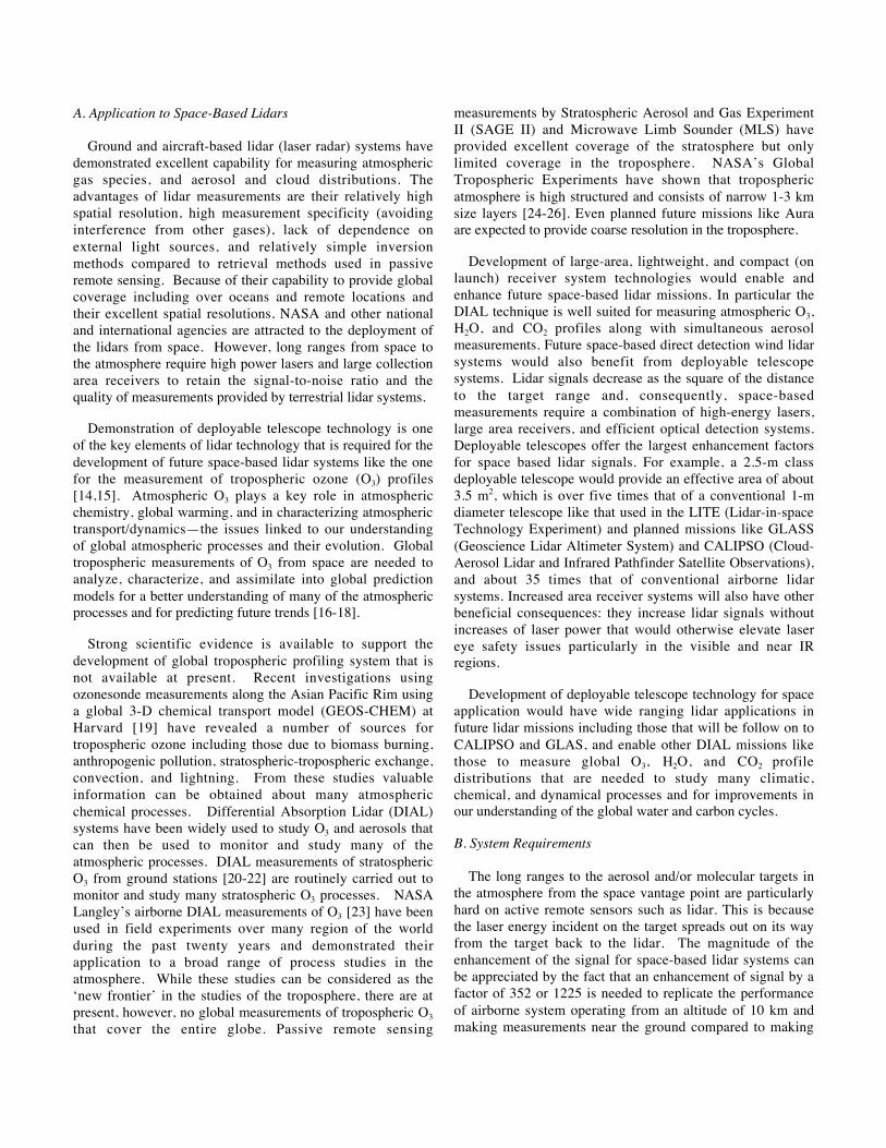
Component experiments will be developed to validate themechanical performance of selected components of thesingle-petal test article. A rendering of the component testapparatus design is shown in Figure 3.
Component test articles will include the mechanical latchdesign described in Section III.A above. They may alsoinclude other components of the single-petal test article thatare determined to have model uncertainty significant enoughto justify the experiment. Currently, this includes theprecision hinges, but may also include material coupons.
The component experiments will control and vary asappropriate:
(a) the thermal environment
(b) the deployment state history, and
(c) the elastomechanical boundary conditions and loads
These will be consistent with the actual in situ influences thecomponent experiences within the structure so as to facilitatethe modeling of the component within the structure.
A unique approach has been developed for actuating thisexperiment. Because of the nonlinearity inherent in themechanism mechanics and dynamics, the boundaryconditions during the test become important considerations inthe interpretation of the results. We have developed a
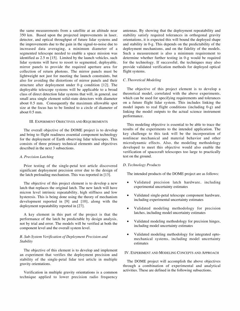
technique known as COIL (Component-in-the-Loop), whichsimulates the compliance of the rest of the structure at theboundaries of the component test. This was reported in [28].Figure 4 shows a rendering of the COIL actuation hexapods.Each hexapod controls six degrees of freedom (DOF) offorces and moments at a given boundary location.
B. Single-Petal Experiment
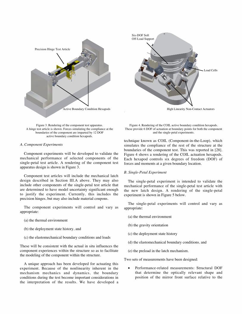
The single-petal experiment is intended to validate themechanical performance of the single-petal test article withthe new latch design. A rendering of the single-petalexperiment is shown in Figure 5 below.
The single-petal experiments will control and vary asappropriate:
(a) the thermal environment
(b) the gravity orientation
(c) the deployment state history
(d) the elastomechanical boundary conditions, and
(e) the preload in the latch mechanism.
Two sets of measurements have been designed:
• Performance-related measurements: Structural DOFthat determine the optically relevant shape andposition of the mirror front surface relative to the
Precision Hinge Test Article
Active Boundary Condition Hexapods
Figure 3. Rendering of the component test apparatus.A hinge test article is shown. Forces simulating the compliance at the
boundaries of the component are imparted by 12 DOFactive boundary condition hexapods.
Load Cells
High Linearity Non-Contact Actuators
Six-DOF SoftOff-Load Support
Figure 4. Rendering of the COIL active boundary condition hexapods.These provide 6 DOF of actuation at boundary points for both the component
and the single-petal experiments.
interface between the single-petal test article and itsintended attachment to the remainder of the telescope.
• Modeling-related measurements: Structural DOF thatprovide sufficient information to determine likelysources of error within a comparative model of theexperiment.
These DOF will be measured with respect to a highlystable metrology frame that rests behind the test article, asindicated in the rendering. The metrology frame is designedto have both high thermal and vibration stability. Deviationsless than 20 nanometers in any axis at all measurementlocations are expected.
The measurement sensors include high precisionaccelerometers and eddy current sensors. In addition, theexperiment uses a special, high-resolution videometry systemwith 10-20 nanometer accuracy. This videometry systemprovides a second witness to the static stability anddeployment repeatability measured by the eddy currentsensors.
As in the component tests, the single-petal tests alsoincorporate active boundary condition COIL hexapods. Theseare attached at three locations, providing 18 DOF ofboundary condition control. Not shown in the figure is a load
application frame that supports 2 additional actuators thatapply loads to the tip of the test article. This will be used totest the hypothesis that the effect of gravity is identical to theeffect of static stress induced in the structure and thedeployment mechanisms.
C. Models
The DOME project will develop and apply the followingtheoretical models:
• Component Models: Predict the observations of thecomponent experiments
• Single-Petal Model: Predicts the observations of thesingle-petal experiment.
• Flight System Model: Predict the performance of thefull six-petal deployable telescope in zero gravity.
Each model includes tolerances on the prediction forcomparing with the statistical descriptions of theexperimental data. Once the component models have beencorrelated with the component experiments, these are thenincorporated into the single-petal model. Likewise, once thesingle-petal model has been correlated with the single-petalexperiments, it is incorporated into the flight system model.This results in a prediction of the flight system performanceincluding statistical estimates of the uncertainty. The outputof this flight system model will be a prediction of the opticalsystem performance.
V. CONCLUSIONS
This paper has reviewed the objectives and design of theDeployable Optics Modeling Experiments ACT project. Theoverall objective of this project is to advance key technologyfor the deployment of space-based lidar receivers from 2 to10 meters in diameter. The project is developing a series ofcomponent and subsystem experiments, correlated withmodels, that will lead to a prediction of on-orbit performanceof the telescope.
ACKNOWLEDGEMENTS
This research was sponsored by the NASA LangleyResearch Center through an Earth Science Technology Office(ESTO) Advanced Component Technology (ACT) projectunder contract NAS1-03009, with W.C. Edwards as thetechnical monitor.
REFERENCES
1. Hedgepeth, John M., “Critical Requirements for theDesign of Large Space Structures,” NASA CR-3484,1981.
Single-PetalTest Article
MetrologyFrame
Active BoundaryCondition Hexapods
Figure 5. Rendering of the single-petal experiment apparatus.
2. Hedgepeth, John M. “Support Structures for LargeInfrared Telescopes” NASA CR-3800, 1984.
3. Bely, P. -Y. “The NGST Yardstick Mission",Proceedings of the 34th Liege International AstrophysicsColloquium, Liege, Belgium, June, 1998, p. 159-166.
4. Lake, Mark S., "Launching a 25-Meter Space Telescope:Are Astronauts a Key to the Next Technically LogicalStep After NGST?" IEEE-2001-460, Presented at the2001 IEEE Aerospace Conference, Big Sky, Montana,March, 2001
5. Lake, M. S., Peterson, L. D., and Levine, M. B., “ARationale for Defining Structural Requirements forLarge Space Telescopes,” Journal of Spacecraft andRockets, Vol 39, No 5, September-October 2002.
6. Lake, M.S., Peterson, L.D. and Mikulas, M.M. “SpaceStructures on the Back of an Envelope: JohnHedgepeth’s Approach to Design” AIAA-2003-1448,Proceedings of the 44th Structures, Structural Dynamicsand Materials Conference, Norfolk, VA, April, 2003.
7. Peterson, L.D. and Hinkle, J.D. “Implications ofStructural Design Requirements for Selection of FutureSpace Telescope Architectures” SPIE-5166-05,Proceedings of the SPIE Annual Meeting, San Diego,California, August, 2003.
8. Thompson, M.W. “The AstroMesh DeployableReflector” Proceedings of Fifth International SatelliteConference (IMSC’97), Pasadena, California, June 16-18, 1997, JPL Publication 97-11, pp 393-398.
9. Lake, Mark S. and Hachkowski, M. Roman, "Design ofMechanisms for Deployable Optical Instruments:Guidelines for Reducing Hysteresis" NASA-TM-2000-210089, March, 2000.
10. Hachkowski, M.R. “Reduction of Hysteresis in the Load-Displacement Response of Precision DeploymentMechanisms through Load Path Management”Universityof Colorado Doctoral Dissertation, CU-CAS-98-07, May1998.
11. Peterson, L.D. and Hinkle, J.D. “Microdynamic DesignRequirements for Large Space Structures”, AIAA-2003-1451, Proceedings of the 44th Structures, StructuralDynamics and Materials Conference, Norfolk, Virginia,April, 2003.
12. Lake, Mark S., Phelps, James E., Dyer, Jack E., Caudle,David A., Tam, Anthony, Escobedo, Javier, and Kasl,Eldon P. "A Deployable Primary Mirror for SpaceTelescopes" SPIE-3785-02, Denver, Colorado, July,1999.
13. Heald, J.C. and Peterson, L.D. “DeploymentRepeatability of a Space Telescope Reflector Petal.” J.Spacecraft and Rockets, Vol. 39, No. 5, September-October 2002, pp 771-779.
14. Browell, E. V., S. Ismail, T. C. McElroy, R. M. Hoff,and A. E. Dudelzak, Global measurements of ozone andaerosol distributions with a space-based lidar system,AGY Fall meeting, Dec. 8-12, 1997.
15. J. H. Stadler, E. V. Browell, S. Ismail, A. E. Dudelzak,and D. J. Ball, “Ozone Research with AdvancedCooperative Experiment (ORACLE) ImplementationStudy,” Nineteenth International Laser RadarConference, NASA/CP-1998-207671/PT2, 945-947, July1998.
16. Berntsen, T. K., G. Myhre, F. Stordal, I. S. A. Isaksen,Time evolution of tropospheric ozone and its radiativeforcing, J. Geophys. Res. 105, 8915-8930, 2000.
17. Collins, W. J., D. S. Stevenson, C. E. Johnson, and R. G.Derwent, The European regional ozone distribution andits links with the global scale for the years 1992 and2015, Atmos.Environ. 34, 255-267, 2000.
18. Kiehl, J. T., T. L. Schneider, R. W. Portmann, and SSolomon, Climate forcing due to tropospheric andstratospheric ozone, J. Geophys. Res., 104, 31,239-31,254, 1999.
19. Liu, H. D. J. Jacob, L. Y. Chan, S. J. Oltmans, I. Bey etal, Sources of tropospheric ozone along the Asian Pacificrim: an analysis of ozonsonde observations, Submitted toJ. Geophys. Res., december 2001.
20. Leblanc, T. and I. S. McDermid, stratospheric ozoneclimatology from lidar measurements at Table Mountainand Mauna Loa, J. Geophys. Res. 105, 14613-14623,2000.
21. Steinbrecht, W., Neuber, R., V Gathen, P, Wahl, P,McGee, T. J., Gross, M. R, Klein, U., Langer, J., Resultsof the 1998 Ny-Aolesund Ozone MonitoringIntercomparison. J. Geophys. Res., 104, 30515-30523,1999.
22. McGee, T. J., M. Gross, U. N. Singh, J. J. Butler, and P.Kinvilakani, Improved stratospheric ozone lidar, Opt.Eng. 34, 1421-1430, 1995.
23. Browell, E. V., S. Ismail, and W. B. Grant, DifferentialAbsorption lidar (DIAL) from air and space, Appl. Opt.B., 67, 399-410, 1998.
24. Newell, R. E., V. Thouret, J. Y. N. Cho, P. Stoller, A.Marenco, and H. G. Smit, Ubiquity of quasi-horizontallayers in the troposphere, Nature, 398, 316-319, 1999.
25. Fenn, M., E. V. Browell, C. F. Butler, W. B. Grant et al.,Ozone and aerosol distributions and air masscharacteristics over the South Pacific during the burningseason, J. Geophys. Res., 104, 16,197-16,212, 1999.
26. Browell, E. V., M. A. Fenn, W. B. Grant, M. E. Clayton,J. Fishman, A. S. Bachmeier, B. E. Anderson, G. L.Gregory et al., Ozone and aerosol distributions and airmass characteristics over the South Atlantic Basin duringthe burning season, J. Geophys. Res., 101, 24,043-24,068, 1996.
27. Heald, J.C. "Deployment Repeatability in MechanicallyJointed Precision Structures" University of ColoradoDoctoral Dissertation, Report No. CU-CAS-03-06, July2003.
28. Footdale, J.N., Hinkle, J.D. and Peterson, L.D.,"Component in the Loop Model Verification for LargePrecision Spacecraft Structures" AIAA-2004-1794,Proceedings of the 45th AIAA/ASME/ASCE/AHS/ASCStructures, Structural Dynamics & MaterialsConference, 19 - 22 April 2004, Palm Springs,California.