Embed Size (px)
Citation preview

Department of Veterans Affairs
Real Time Location System (RTLS) ESE
Interfaces Technical Manual
March 2017 Version 3.2

This page intentionally left blank
RTLS ESE Interfaces i March 2017 Technical Manual
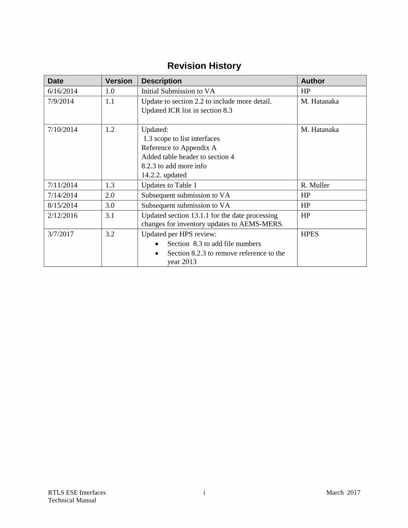
Revision History Date Version Description Author 6/16/2014 1.0 Initial Submission to VA HP 7/9/2014 1.1 Update to section 2.2 to include more detail.
Updated ICR list in section 8.3
M. Hatanaka
7/10/2014 1.2 Updated: 1.3 scope to list interfaces Reference to Appendix A Added table header to section 4 8.2.3 to add more info 14.2.2. updated
M. Hatanaka
7/11/2014 1.3 Updates to Table 1 R. Muller 7/14/2014 2.0 Subsequent submission to VA HP 8/15/2014 3.0 Subsequent submission to VA HP 2/12/2016 3.1 Updated section 13.1.1 for the date processing
changes for inventory updates to AEMS-MERS. HP
3/7/2017 3.2 Updated per HPS review: • Section 8.3 to add file numbers • Section 8.2.3 to remove reference to the
year 2013
HPES

RTLS ESE Interfaces ii March 2017 Technical Manual
This page intentionally left blank

RTLS ESE Interfaces iii March 2017 Technical Manual
Table of Contents 1. Introduction ........................................................................................... 1
1.1. Overview .............................................................................................................. 1 1.2. Purpose ............................................................................................................... 3 1.3. Scope ................................................................................................................... 3 1.4. References .......................................................................................................... 3
2. Implementation and Maintenance ........................................................ 3 2.1. Manage AEMS-MERS Interface Application Jobs ............................................ 4 2.2. Modify the Timeframe for the Queue in AEMS-MERS ..................................... 4 2.3. Modify the Timing/Frequency of the GIP-WaveMark Interface ....................... 5
3. Files ....................................................................................................... 5 3.1. PENDING RTLS EVENTS (#6930) ...................................................................... 5
4. Routines ................................................................................................ 6
5. Exported Options .................................................................................. 8 5.1. RTLS Interface Menu [VIAA01 RTLS RPC MENU] ......................................... 8 5.2. VIAA MAKE WEB CALL TO MULE Option ........................................................ 8
6. Archiving ............................................................................................... 9
7. Callable Routines/Entry Points/Application Program Interfaces....... 9
8. External Relationships ......................................................................... 9 8.1. Minimum Software Requirements ..................................................................... 9 8.2. VistA and Other Software Interactions ........................................................... 10
8.2.1. AEMS-MERS Interface to Intelligent InSites RTLS .................................. 10 8.2.2. GIP Interface to WaveMark RTLS .............................................................. 10 8.2.3. PATIENT File Interface to WaveMark ........................................................ 11 8.2.4. EMPLOYEE Interface to WaveMark .......................................................... 12 8.2.5. CART-CL Interface to WaveMark .............................................................. 13
8.3. Integration Agreements (IA) ............................................................................ 13
9. Internal Relationships ........................................................................ 15
10. Global Variables ................................................................................ 15
11. Glossary ............................................................................................ 15
12. Additional Useful Information .......................................................... 16 12.1. External Interfaces .......................................................................................... 16 12.2. Cross-References ........................................................................................... 16 12.3. Software Security ........................................................................................... 16
13. Appendix A: RTLS-VistA Interface Configuration Tool .................. 16 13.1. Getting Started ................................................................................................ 17

RTLS ESE Interfaces iv March 2017 Technical Manual
13.1.1. Understanding the AEMS-MERS RTLS Jobs ......................................... 17 13.1.2. Understanding the Job Scheduling Mechanism ................................... 18 13.1.3. Accessing the Snap-In within Intelligent InSites ................................... 19
13.2. Initial Set Up .................................................................................................... 21 13.2.1. Adding a VISN .......................................................................................... 21 13.2.2. Adding a VA Facility definition ............................................................... 22 13.2.3. Adding a Job ............................................................................................ 24
13.3. Managing Existing Jobs ................................................................................. 26 13.3.1. Modifying a Job Schedule ....................................................................... 26 13.3.2. Running a Job on Demand ...................................................................... 27 13.3.3. Suspending a Job .................................................................................... 28 13.3.4. Deleting a Job ........................................................................................... 29
13.4. Managing an Existing VA Facility Definition ................................................ 30 13.4.1. Modifying a VA Facility Definition .......................................................... 30 13.4.2. Deleting a VA Facility Definition ............................................................. 32
14. Appendix B: Troubleshooting .......................................................... 33 14.1. RTLS Interface Application ............................................................................ 33
14.1.1. Understanding the Log Files ................................................................... 33 14.1.2. Troubleshooting ....................................................................................... 33
14.2. CART-CL/WaveMark Interface ....................................................................... 36 14.2.1. Understanding the High Level Operations ............................................. 36 14.2.2. Troubleshooting ....................................................................................... 37
14.3. Frequently Asked Questions (FAQ) .............................................................. 37
RTLS ESE Interfaces 1 March 2017 Technical Manual
1. Introduction The Department of Veterans Affairs (VA) is implementing an enterprise-wide solution for a Real Time Location System (RTLS) for the VA. RTLS will be used for the purpose of tracking objects such as equipment, supplies, and instruments. RTLS has the ability to locate patients and staff as well. In addition, environmental monitoring (i.e. humidity and temperature) of equipment and rooms is included in the solution. Multiple RFID tags and technologies are being deployed (using existing wireless infrastructure, or wired infrastructure) to meet specifications and specialized needs.
The Veterans Health Administration (VHA) has a requirement to implement RTLS in all its facilities over the next several years. Each VHA Veterans Integrated Service Network (VISN) will have its own RTLS database(s) that will be accessible via a single, standard user interface. The RTLS at each VISN must also be capable of exchanging data with VA information systems (e.g. VistA) and with a single national information system, (the National Data Repository [NDR]), that will serve to aggregate and display RTLS data from the VISN-level RTLS databases. The NDR, at a minimum, will be an information based solution with open, flexible architecture that will house sophisticated business intelligence, predictive analytics, and reporting capabilities used for process improvement, business and financial analytics, workflow analysis and research analysis.
1.1. Overview The RTLS solution consists of the tags (active, passive, and 2D barcodes), the databases associated with the collection of the data from the tags, and a Graphical User Interface (GUI) software application(s) that allow users to interact with the RTLS data. Figure 1 depicts the system overview and a breakdown of the major components of RTLS.

RTLS ESE Interfaces 2 March 2017 Technical Manual
Figure 1 RTLS Overview
The RTLS ESE Interface Applications have been developed to connect the VA legacy systems to RTLS. The RTLS Interface Applications orchestrate specific Mule Enterprise Service Bus (ESB) process flows to support the following functional areas:
• AEMS-MERS equipment synchronization with RTLS
• GIP Inventory supply synchronization with WaveMark
• Search of VistA employee data from within the WaveMark system
• Search of VistA patient data from within the WaveMark system
Also included in the VA RTLS solution is an interface that provides CART-CL with supply usage information related to a patient captured by the WaveMark system.
The environment needed to run the RTLS Interface Applications is multi-server and includes the following distinct deployment components:
• RTLS VistA Patch (KIDS build)

RTLS ESE Interfaces 3 March 2017 Technical Manual
• WebLogic VistaService Web Services
• RTLS ESB application component
• RTLS-VistA Interface Configuration Tool
1.2. Purpose The purpose of this manual is to provide the necessary technical information about the structure and function of the logical components of the RTLS Interface Applications to aid technical support staff with the configuration, maintenance and troubleshooting of the individual interface components that comprise the software solution.
1.3. Scope The manual describes how to configure and maintain the RTLS Interface Applications. The interfaces covered in the RTLS Interface Applications are:
• Automated Engineering Management System/Medical Equipment Reporting System (AEMS-MERS) Intelligent InSites Interface
• Cardiovascular Assessment Reporting and Tracking system for Catheterization Labs (CART-CL) WaveMark Interface
• Employee (VistA NEW PERSON File) WaveMark Interface
• Patient (VistA PATIENT File) WaveMark Interface
• Generic Inventory Package (GIP) WaveMark Interface
Installation of the RTLS Interface Applications is covered in the RTLS ESE Installation Guide. Information on how end users interact with the interface components is covered in the RTLS ESE Interfaces User Guide.
1.4. References • [RTLS ESE Installation Guide] Real Time Location Systems (RTLS) ESE Installation Guide
• [RTLS ESE Security Plan] Real Time Location Systems (RTLS) ESE Security Plan
• [RTLS ESE Interfaces User Guide] Real Time Location Systems (RTLS) ESE Interfaces User Guide
• VA WaveMark User Guide
2. Implementation and Maintenance The VA RTLS Program is an incremental program. The RTLS Interface Application along with RTLS hardware and software will be progressively deployed to locations within the VA VISNs and CMOP. Deployment and installation is planned as an incremental rollout to each VISN and CMOP until all VISNs/CMOP are deployed.
The post-installation tasks needed to configure the RTLS Interface Application are covered in the RTLS ESE Installation Guide. Beyond the initial installation and configuration, there is minimal maintenance to be performed. The following sections provide more information about maintenance tasks.

RTLS ESE Interfaces 4 March 2017 Technical Manual
2.1. Manage AEMS-MERS Interface Application Jobs The AEMS-MERS/RTLS interface is comprised of several interface jobs that synchronize equipment tracking data between VistA and RTLS. These jobs are scheduled through the RTLS-VistA Interface Configuration Tool described in Section 13 Appendix A: RTLS-VistA Interface Configuration Tool.
2.2. Modify the Timeframe for the Queue in AEMS-MERS The RTLS VistA Patch contains an option, ‘Make Web Call to Mule’ [VIAA MAKE WEB CALL TO MULE], to send Engineering file changes (via MUMPS Style Cross Reference events) to the RTLS database via a Mule server. The option is a queue process that can check on user-specified intervals, to see if there are any record changes from files EQUIPMENT INV (#6914) and ENG SPACE (#6928) that need to be transmitted to RTLS. To modify the timeframe for the record transmission, use the following steps:
Note: Recommended timeframe for the queue is between 1 and 5 minutes.
1. From the System Manager Menu, select Taskman Management. 2. From the Taskman Management Menu, select Schedule/Unschedule Options. 3. At the “Select OPTION to schedule or reschedule” prompt, type VIAA MAKE WEB CALL TO
MULE 4. At the “QUEUED TO RUN AT WHAT TIME” prompt, type the time of day expressed in
military time for the job to begin preceded by the characters “T@”. For example, T@13:00 would represent the job beginning at 1:00 PM each day.
5. At the “RESCHEDULING FREQUENCY” prompt, type the number of seconds between job runs followed by the letter “S”. For example, 180S would represent a 3 minute interval.
See Figure 2 for an example of the Schedule Make Web Call to Mule Option steps and results.
Figure 2 Example of Scheduling the new option _ CPM>D ^XUP Setting up programmer environment This is a TEST account. Terminal Type set to: C-VT100 Select OPTION NAME: EVE Systems Manager Menu Core Applications ... Device Management ... FM VA FileMan ... Menu Management ... Programmer Options ... Operations Management ... Spool Management ... Information Security Officer Menu ... Taskman Management ... User Management ... Application Utilities ... Capacity Management ... Manage Mailman ... <CPM> Select Systems Manager Menu Option: TASKman Management

RTLS ESE Interfaces 5 March 2017 Technical Manual
Schedule/Unschedule Options One-time Option Queue Taskman Management Utilities ... List Tasks Dequeue Tasks Requeue Tasks Delete Tasks Print Options that are Scheduled to run Cleanup Task List Print Options Recommended for Queueing <CPM> Select Taskman Management Option: SCHEDULe/Unschedule Options Select OPTION to schedule or reschedule: VIAA MAKE WEB CALL TO MULE Make W eb Call to Mule ...OK? Yes// (Yes) (R) Edit Option Schedule Option Name: VIAA MAKE WEB CALL TO MULE Menu Text: Make Web Call to Mule TASK ID: 490309 __________________________________________________________________________ QUEUED TO RUN AT WHAT TIME: T@10:50 <press enter> enter a new date and time here DEVICE FOR QUEUED JOB OUTPUT: QUEUED TO RUN ON VOLUME SET: RESCHEDULING FREQUENCY: 300S (press enter> option will run every 5 minutes TASK PARAMETERS: SPECIAL QUEUEING: ______________________________________________________________________________
2.3. Modify the Timing/Frequency of the GIP-WaveMark Interface The GIP-WaveMark interface has two scheduled jobs that work in unison to keep current WaveMark inventory supply counts updated in GIP. These scheduled jobs are managed by end users (i.e. VA Inventory Managers). Instructions on how to run the interfaces is described in the VA WaveMark User Guide.
3. Files The RTLS Interface Application contains one new VistA file called PENDING RTLS EVENT (#6930).
3.1. PENDING RTLS EVENTS (#6930)

RTLS ESE Interfaces 6 March 2017 Technical Manual
As part of the synchronization of equipment details between AEMS-MERS and RTLS, a unidirectional Mule ESB flow detects changes in equipment inventory files in AEMS-MERS and pushes the specified fields to the RTLS system. This is a triggered process. The MUMPS Style Cross References on the EQUIPMENT INV (#6914) file queue the triggered events in the PENDING RTLS EVENTS (#6930) file. A VistA TaskMan job processes the pending entries on a configured polling interval (e.g. 1-5 minutes) and issues an HTTP request to the Mule flow via the HWSC (Health-e-Vet Web Service Client). A MUMPS Style Cross Reference identifies an action that should take place when the value of fields defined in that cross-reference is changed. This provides timely updates of RTLS with data maintained in AEMS-MERS. When changes occur in the ENG SPACE file (#6928), a similar triggered process is completed.
The PENDING RTLS EVENTS file introduces a resiliency feature by saving record changes that could not be sent to RTLS when the Mule server is offline for any reason. Record changes are sent when communication is re-established.
For more information about the fields within the PENDING RTLS EVENTS file, complete the following steps:
1. Login to VistA with your access and verify codes. 2. From the Systems Manager Menu, select VA FileMan. 3. Select Data Dictionary Utilities. 4. Select List File Attributes.
The PENDING RTLS EVENTS file does not have any special templates.
The PENDING RTLS EVENTS file is also described in the AEMS-MERS/Intelligent InSites SDD.
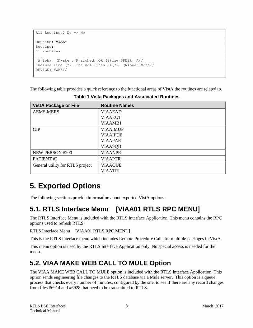
4. Routines For a brief description of the routines created to support the RTLS Interface Application, use the First Line Routine Print [XU FIRST LINE PRINT] menu option by completing the following steps:
1. Login to VistA with your access and verify codes. 2. From the Systems Manager Menu, select Programmer Options. 3. Select Routine Tools. 4. From the Routine Tools Menu, select First Line Routine Print 5. At the “All Routines?” prompt, press enter. 6. At the “Routine:” prompt, type VIAA* 7. At the second “Routine:” prompt, press enter.
The number of routines included in the VIAA patch is displayed.
8. At the “(A)lpha, (D)ate ,(P)atched…” prompt, press enter. 9. At the “Include line (2)…” prompt, press enter. 10. At the “DEVICE: HOME//” prompt, press enter. The list of routine names and a brief description
of each is displayed. See Vista for an example of the steps.
Figure 3 Displaying routines in VistA Core Applications ... Device Management ...

RTLS ESE Interfaces 7 March 2017 Technical Manual
FM VA FileMan ... Menu Management ... Programmer Options ... Operations Management ... Spool Management ... Information Security Officer Menu ... Taskman Management ... HL7 Main Menu ... User Management ... Application Utilities ... Capacity Planning ... Manage Mailman ... Select Systems Manager Menu <TEST ACCOUNT> Option: PROgrammer Options KIDS Kernel Installation & Distribution System ... NTEG Build an 'NTEG' routine for a package PG Programmer mode Calculate and Show Checksum Values Delete Unreferenced Options Error Processing ... Global Block Count List Global Map Pointer Relations Number base changer Routine Tools ... Test an option not in your menu Verifier Tools Menu ... Select Programmer Options <TEST ACCOUNT> Option: ROUTINE Tools %Index of Routines Check Routines on Other CPUs Compare local/national checksums report Compare routines on tape to disk Compare two routines Delete Routines First Line Routine Print Flow Chart Entire Routine Flow Chart from Entry Point Group Routine Edit Input routines List Routines Load/refresh checksum values into ROUTINE file Output routines Routine Edit Routines by Patch Number Variable changer Version Number Update Select Routine Tools <TEST ACCOUNT> Option: FIRST Line Routine Print PRINTS FIRST LINES
RTLS ESE Interfaces 8 March 2017 Technical Manual
All Routines? No => No Routine: VIAA* Routine: 11 routines (A)lpha, (D)ate ,(P)atched, OR (S)ize ORDER: A// Include line (2), Include lines 2&(3), (N)one: None// DEVICE: HOME//
The following table provides a quick reference to the functional areas of VistA the routines are related to.
Table 1 Vista Packages and Associated Routines
VistA Package or File Routine Names AEMS-MERS VIAAEAD
VIAAEUT VIAAMB1
GIP VIAAIMUP VIAAIPDE VIAAPAR VIAASQH
NEW PERSON #200 VIAANPR PATIENT #2 VIAAPTR General utility for RTLS project VIAAQUE
VIAATRI
5. Exported Options The following sections provide information about exported VistA options.
5.1. RTLS Interface Menu [VIAA01 RTLS RPC MENU] The RTLS Interface Menu is included with the RTLS Interface Application. This menu contains the RPC options used to refresh RTLS.
RTLS Interface Menu [VIAA01 RTLS RPC MENU]
This is the RTLS interface menu which includes Remote Procedure Calls for multiple packages in VistA.
This menu option is used by the RTLS Interface Application only. No special access is needed for the menu.
5.2. VIAA MAKE WEB CALL TO MULE Option The VIAA MAKE WEB CALL TO MULE option is included with the RTLS Interface Application. This option sends engineering file changes to the RTLS database via a Mule server. This option is a queue process that checks every number of minutes, configured by the site, to see if there are any record changes from files #6914 and #6928 that need to be transmitted to RTLS.

RTLS ESE Interfaces 9 March 2017 Technical Manual
At installation, the job should be scheduled to run every 1 to 5 minutes for effective record transmission. The time interval is user-specified. To adjust this time interval, see section 2.2.
6. Archiving The RTLS Interface Application does not require archiving.
7. Callable Routines/Entry Points/Application Program Interfaces The RTLS VistA patch (under namespace VIAA) has one routine that is called from multiple fields in the data dictionaries for files #6914 and #6928. The entry tag is WC and the routine is VIAATRI. VIAATRI is designed to be used for the RTLS Interface Application only.
8. External Relationships The following sections provide information about relationships between VistA and the external software components that comprise the RTLS solution.
8.1. Minimum Software Requirements The following tables list the software and minimum versions required for the RTLS Interface Application.
Table 2 Prerequisite VistA software
Software Application or Patch Namespace Version AEMS-MERS (Automated Engineering Management System-Medical Equipment Reporting System)
EN 7.0
IFCAP (Integrated Funds Distribution, Control Point Activity, Accounting and Procurement)
PRC 5.1
Kernel XU 8.0 VA FileMan DI 22.0
Table 3 Non-VistA Required Software
Software Application Version Intelligent InSites RTLS 4.6 Mule Enterprise Edition 3.3.2 Oracle JRockit R28.2.5-4.1.0 64 bit (for WebLogic) Oracle WebLogic Enterprise Edition 10.3.6 64 bit Red Hat Enterprise Linux (RHEL) 6.5 Sun/Oracle JDK 1.6 update 45 (for Mule ESB) WaveMark EncounterLink 2.5 WaveMark Engine 5.27

RTLS ESE Interfaces 10 March 2017 Technical Manual
Software Application Version WaveMark InterfaceEngine 1.3 MMC Console 3.4.1 Microsoft SQL Server 2008 R2 or later
Note: Your versions to install may differ based on later agreement between RTLS and local VA infrastructure.
8.2. VistA and Other Software Interactions The overall RTLS system is used for the purpose of tracking objects such as equipment, supplies, and instruments. RTLS has the ability to locate staff and patients as well. The RTLS Interface Application has been developed to connect the VA legacy systems to RTLS and serves various different functional areas. The external relationships between the VA legacy systems (i.e. VistA and CART-CL) and other software, including Commercial off the Shelf (COTS) products, are described in the following sections.
8.2.1. AEMS-MERS Interface to Intelligent InSites RTLS AEMS-MERS, also known as the Engineering Package within VistA, is in use today at all VHA facilities and some other VA entities. Equipment is currently tagged with 2D barcodes, and details about the equipment are entered into AEMS-MERS.
Intelligent InSites RTLS is a COTS real time location system designed for the healthcare industry. RTLS gathers data from real time location, condition sensing, and other systems, then delivers meaningful real time actionable information for reporting and analytical purposes.
The bi-directional interface between AEMS-MERS and RTLS provides RTLS with details about tagged AEMS-MERS equipment and provides AEMS-MERS with updated equipment location information.
Through the RTLS Interface Application, AEMS-MERS sends equipment details from the EQUIPMENT INV file (#6914) to the RTLS InSites database. The RTLS system captures current equipment location information through active and passive RTLS tags and sends updated location information to the EQUIPMENT INV (#6914) file.
8.2.2. GIP Interface to WaveMark RTLS The Generic Inventory Package (GIP) is a module of VistA Integrated Funds Control, Accounting and Procurement (IFCAP) that resides locally and manages the receipt, distribution, and maintenance of stock items received for the supply warehouse from outside vendors and distributed to primary inventory points. GIP is the system of record for expendable/consumable supplies, such as those typically stored in cabinets and storage rooms and used for patient care.
WaveMark is a COTS product. WaveMark uses RFID enabled cabinets and Point of Use Stations (XPOS) to maintain an accurate inventory of passively tagged GIP expendable/consumable supplies stored in WaveMark cabinets. The WaveMark cabinets come in many form factors as shown in Figure 4. Figure 5 illustrates how an item is scanned into the WaveMark system using an XPOS.
The RTLS Interface Application includes code to implement a bi-directional flow of information between GIP and WaveMark for VA Cath Lab supplies. GIP sends a list of approved expendable/consumable supplies (i.e. ITEM MASTER NUMBERs and associated reference data) to WaveMark. GIP receives from WaveMark periodic inventory updates of all items stored in the WaveMark Smart Cabinets.

RTLS ESE Interfaces 11 March 2017 Technical Manual
Figure 4 WaveMark Smart Cabinets
Figure 5 WaveMark Pont of use Station
Through the GIP-WaveMark interaction, a list of approved expendable/consumable GIP supplies is sent to WaveMark from the ITEM MASTER file (#441). The WaveMark passive tagging of expendable/consumable supplies provides GIP with an accurate inventory of supplies. The WaveMark system updates inventory levels as well as par values for the supplies that are synchronized between the two systems in the GENERIC INVENTORY file (#445).
8.2.3. PATIENT File Interface to WaveMark The PATIENT file/WaveMark interface performs a real time search for patient information to help positively identify a patient before a procedure.
VHA Directive 2010-023 states “It is VHA policy that any VHA health care provider performing a surgery or invasive procedure must complete specific steps to ensure that the procedure is performed on the correct patient, at the correct site, and with the correct implant, if applicable.”
Improving the accuracy of patient identification is one of the National Patient Safety Goals (NPSGs). The Patient Safety Advisory Group advises The Joint Commission on the development and updating of NPSGs.
As part of the RTLS interface applications, the WaveMark system helps Cath Lab nurses and technicians verify a patient’s identity by using a scanner attached to the WaveMark XPOS to scan the patient’s wristband. The WaveMark XPOS uses the unique identifier located on the wristband to send a request for information from the VistA PATIENT (#2) file. After data retrieval from VistA, the patient name, gender, and date of birth are displayed on the WaveMark XPOS. These data elements are not stored in the WaveMark system.The Patient ICN is the only data element stored. Figure 6 shows what the WaveMark XPOS will display to the nurses and technicians responsible for verifying the patient’s identity.

RTLS ESE Interfaces 12 March 2017 Technical Manual
Figure 6 WaveMark XPOS Patient Confirmation Window
8.2.4. EMPLOYEE Interface to WaveMark The VistA Employee Interface (NEW PERSON (#200) file to WaveMark helps identify staff to ensure that the correct staff is associated with patient procedures and facilitates data accuracy and normalization.
As part of the goal of improving employee identity verification for VA healthcare, the Joint Commission recommends positively identifying the employee. The accurate identification of employee is improved by using a unique identifier IEN (Internal Entry Number). The real-time lookup of the employee information that is relevant to the process is retrieved and displayed for the clinician to confirm through WaveMark Point of Use Station (XPOS).
The WaveMark Engine exposes a Web-based UI that allows administrators to manage the employee lists in the WaveMark system. Using the Manage Lists tool users are able to add and remove doctors and staff from the WaveMark system. To add employees, the administrator enters the last name of the employee and clicks a button that will invoke the interface and perform the lookup. The returned matches from the VistA NEW PERSON (#200) file will be displayed. This display includes additional identifying data such as the full first and last name, title, and service/section to allow the administrator to select the correct employee if more than one possible match is returned.
The WaveMark XPOS systems are installed at the point of care either in the procedure room or the control room of the procedure room. The XPOS system has a graphical user interface (GUI) that is navigated and controlled by the end users using a touch screen. Figure 7 shows what the WaveMark system will display on the XPOS for the staff list.

RTLS ESE Interfaces 13 March 2017 Technical Manual
Figure 7 Staff List displayed on the WaveMark XPOS
The interface exposes Internal Entry Number (IEN), name, and position (e.g., doctor, nurse, or technician) information from the Vista NEW PERSON file (#200) for staff identification.
8.2.5. CART-CL Interface to WaveMark VA currently employs inventory tools, such as GIP, to assign codes to individual consumable models as they are deployed at VAMCs. Data about the usage of the consumables is recorded by a system called CART-CL that aggregates all usage data in Cath Labs from all VAMCs. CART-CL is currently used to record consumables used in Cath Labs, such as stents and balloons. CART-CL also tracks patient information and associates it with the used consumables.
This is a software interface that allows the WaveMark system to directly pass specific information to a pair of SQL Server staging tables created in CART-CL exclusively for this purpose. CART-CL does not pass any information to the WaveMark system.
The scheduler in the WaveMark Interface Engine is responsible for dispatching the interface. The Interface Engine includes intelligence to not dispatch more than one instance of this interface at any given time.
8.3. Integration Agreements (IA) ICR # Name Description 5913 READ/WRITE ACCESS TO FILE
#6914 (EQUIPMENT INV) Request permission for READ access via FileMan calls to file #6914 in order to complete RPC queries from Intelligent Insites, and to update the file in VistA when requested. This is part of the RTLS National project to facilitate tracking equipment updates in Engineering, while keeping Intelligent Insites with up to date information.
5914 READ ACCESS TO FILE #6911 (EQUIPMENT CATEGORY)
Request permission for READ access via FileMan calls to file #6911 in order to complete RPC queries from Intelligent Insites. This is part of the RTLS National project to facilitate tracking equipment updates in Engineering, while keeping Intelligent Insites with up to date information.
5915 READ ACCESS TO FILE #6928 (ENG SPACE)
Request permission for READ access via FileMan calls to file #6928 in order to complete RPC queries from Intelligent Insites. This is part of the RTLS National project to facilitate tracking equipment updates in Engineering, while keeping Intelligent Insites with up to date information.
5916 READ ACCESS TO FILE #6917 (CATEGORY STOCK NUMBER)
Request permission for READ access via FileMan calls to file #6917 in order to complete RPC queries from Intelligent Insites. This is part of the RTLS National project to facilitate tracking equipment updates in Engineering, while keeping Intelligent Insites with up to date information.

RTLS ESE Interfaces 14 March 2017 Technical Manual
ICR # Name Description 5917 READ ACCESS TO FILE #6914.1
(CMR) Request permission for READ access via FileMan calls to file #6914.1 in order to complete RPC queries from Intelligent Insites. This is part of the RTLS National project to facilitate tracking equipment updates in Engineering, while keeping Intelligent Insites with up to date information.
5918 READ ACCESS TO FILE #6912 (MANUFACTURER LIST FILE)
Request permission for READ access via FileMan calls to file #6912 in order to complete RPC queries from Intelligent Insites. This is part of the RTLS National project to facilitate tracking equipment updates in Engineering, while keeping Intelligent Insites with up to date information.
5920 READ ACCESS TO FILE #6910 (ENG INIT PARAMETERS)
Request permission for READ access via FileMan calls to file #6910 in order to complete RPC queries from Intelligent Insites. This is part of the RTLS National project to facilitate tracking equipment updates in Engineering, while keeping Intelligent Insites with up to date information.
5921 READ ACCESS TO FILE #441 (ITEM MASTER)
Request permission for READ access via FileMan calls to file #441 in order to complete RPC queries from WaveMark. This is part of the RTLS National project to facilitate tracking clinical supplies in the Cathlab inventory point for GIP.
5922 READ ACCESS TO FILE #440 (VENDOR)
Request permission for READ access via FileMan calls to file #440 in order to complete RPC queries from WaveMark. This is part of the RTLS National project to facilitate tracking clinical supplies in the Cathlab inventory point for GIP.
5923 READ ACCESS TO FILE #445 (GENERIC INVENTORY)
Request permission for READ and WRITE access via FileMan calls to file #445 in order to complete RPC queries from WaveMark. This is part of the RTLS National project to facilitate tracking clinical supplies in the Cath Lab inventory point for GIP.
5993 RTLS POINTING TO FILE 1 The Real Time Location System (RTLS) is requesting approval to point to the file of files (#1). This is to be used for building calls to File Manager API'S dynamically.
6067 READ ACCESS TO FILE #445.6 (GROUP CATEGORY)
Request permission for READ access via FileMan calls to file #445.6 in order to complete RPC queries from WaveMark.
6068 READ ACCESS TO FILE #420.5 (UNIT OF ISSUE)
Request permission for READ access via FileMan calls to file #420.5 in order to complete RPC queries from WaveMark.
6069 ENGINEERING CALL TO RTLS AFTER DATA CHANGE
The RTLS project has requested the Engineering files #6914 and #6928 to have a number of fields modified with MUMPS cross references to report data changes.

RTLS ESE Interfaces 15 March 2017 Technical Manual
ICR # Name Description 10035 PATIENT FILE #2 Any nationally released cross-reference on the
supported fields in this Integration Agreement are “open/supported” for direct global references (as well as reference through VA FileMan).
10060 NEW PERSON FILE #200 All fields supported for Read w/FileMan only for “new” code.
9. Internal Relationships The RTLS Interface Applications contain no options that rely on entry or exit logic from other options.
Updates to files EQUIPMENT INV (#6914) and ENG SPACE (#6928), both through FileMan and the Engineering package options are captured and sent to RTLS.
10. Global Variables The RTLS Interface Applications contain a global variable called ^VIAA. There are no SACC exemptions required in the RTLS Interface Applications.
11. Glossary Term Definition AEMS-MERS Automated Engineering Management System /Medical Equipment
Reporting System API Application Programming Interface CART-CL Clinical Assessment, Reporting, and Tracking Catheterization Lab CMOP Consolidated Mail Order Pharmacy COTS Commercial Off the Shelf CRON CRON Table ESB Enterprise Service Bus ESE Enterprise Systems Engineering GIP Generic Inventory Package GUI Graphical User Interface IA Integration Agreement ICR Integration Control Registration IEN Internal Entry Number IFCAP Integrated Funds Distribution, Control Point Activity, Accounting, and
Procurement JDK Java Development Kit KIDS Kernel Installation & Distribution System MMC Microsoft Management Console MUMPS Massachusetts General Hospital Utility Multi-Programming System

RTLS ESE Interfaces 16 March 2017 Technical Manual
Term Definition NDR National Data Repository RFID Radio Frequency Identification RHEL Red Hat Enterprise Linux RPC Remote Procedure Call RTLS Real Time Location System SACC Standards and Conventions Committee SDD Software Design Document SQA Software Quality Assurance SQL Structured Query Language UI User Interface VA Veterans Affairs VHA Veterans Health Administration VISN Veterans Integrated Service Network XPOS Point of Service Station
12. Additional Useful Information 12.1. External Interfaces The primary purpose of the RPCs developed for the RTLS Interface Applications is to support the RTLS solution. The RPCs are not designed to be called by other software.
12.2. Cross-References N/A
12.3. Software Security Security is addressed in the RTLS ESE Security Plan.
13. Appendix A: RTLS-VistA Interface Configuration Tool The RTLS-VistA Interface Configuration Tool is a software utility for managing jobs between VistA and RTLS. The tool is designed for administrative users of RTLS to have a single location to view and manage network connections and associated jobs within the VISN. The tool is a web application hosted on the interface WebLogic server and is displayed as a Snap-in screen on the Intelligent InSites user interface. The tab in the Intelligent InSites user interface is labeled Interface Apps.
At this time, the tool manages jobs for the AEMS/MERS-RTLS interface, but is designed to be extended if other VistA interfaces are developed requiring scheduled job management. The tool is also designed to be extended to an enterprise level so a single deployment could control all VISNs and associated jobs.
Note: The screen captures used throughout this appendix are from the ES Labs SQA instance and are for illustrative purposes only.

RTLS ESE Interfaces 17 March 2017 Technical Manual
13.1. Getting Started The RTLS-VistA Interface Configuration Tool provides the VA with a mechanism to control the timing and frequency of the jobs that encompass the interface between AEMS-MERS and Intelligent InSites.
The tool is installed as a snap-in on the Intelligent InSites user interface and represents all of the VA facilities and jobs associated with a VISN. The tool is organized in a hierarchical manner: all jobs are associated with a VA facility and all VA facilities are associated with the VISN.
13.1.1. Understanding the AEMS-MERS RTLS Jobs The AEMS-MERS/RTLS interface suite is comprised of several interface jobs that synchronize the equipment tracking data between VistA and RTLS. These jobs are scheduled through the RTLS-VistA Interface Configuration Tool and described below:
• Populate New Asset Details – a job to update newly added AEMS-MERS equipment items in RTLS with additional data elements from the EQUIPMENT INV file (#6914). AEMS-MERS equipment items are initially created in RTLS with a subset of data elements. This job populates RTLS with the additional data elements for all equipment items added since the last job was run.
• Bulk Update – a job to loop through all assets in RTLS for a given station and update the RTLS asset details from AEMS-MERS. The purpose of this process is to periodically re-synchronize all assets between both systems.
• Moved Equipment Inventory - Passive and Active tags - a job to update equipment item locations in AEMS-MERS. When the Moved Equipment Inventory job is run, the location of all AEMS-MERS equipment items tracked in RTLS that have a new location since the last job was run and a inventory date in RTLS that is more recent than AEMS-MERS are updated in AEMS-MERS with the new location and a timestamp.
• Static Active Tagged Equipment Inventory- a job to supplement the information provided by the Moved Equipment Inventory job. This job queries RTLS for active tagged equipment items that have not changed locations and uses the last time the equipment item was “sensed by RTLS” to compare with the last inventory date in AEMS-MERS. AEMS-MERS is updated with a new timestampif the “sensed by RTLS” date is newer than the inventory date in AEMS-MERS.
• Static Passive Tagged Equipment Inventory - a job to supplement the information provided by the Moved Equipment Inventory job. This job queries RTLS for passive tagged equipment items that have not changed locations and uses the last time the equipment item was sensed by RTLS to compare against the inventory date in AEMS-MERS. If the “sensed by RTLS” date is newer than the inventory date in AEMS-MERS, AEMS-MERS is updated with a new timestamp. The last time the item was sensed by RTLS is determined by checking an InSites custom attribute that gets updated by the RTLS passive tag scanner.
• Unmapped Location Report - a job detecting Intelligent InSites locations that do not have RTLS External References tying them back to a VistA space file entry, usually because one does not exist. The job generates a simple report, showing the name of the location from Intelligent InSites and the number of asset movement actions that are tied to that location. The report can be used to research which asset locations may need a corresponding VistA Engineering Space file entry based on the frequency at which they occur.
• Invalid Location Report – a job that detects location ‘space’ external-references that point to invalid Engineering Space file entries. This report lists the RTLS Location Name and the current ‘space’ external-reference value for all locations within a station that point to invalid spaces.
Note: The reports are delivered to designated RTLS system users via the Intelligent InSites user interface.

RTLS ESE Interfaces 18 March 2017 Technical Manual
For more information about the data elements exchanged and the detailed process flow, see the AEMS-MERS ICD.
13.1.2. Understanding the Job Scheduling Mechanism The RTLS-VistA Interface Configuration Tool connects to a Linux job scheduling software utility called cron. Cron schedules jobs to run periodically at fixed times, dates, or intervals. Cron schedules are expressed in a pattern listing seconds, minutes, hour, day of month, month, and day of week, respectively. Cron schedules are stored in a file called a Crontab (CRON TABle), thus the RTLS-VistA Interface Configuration tool field is called Crontab. The format of the Crontab field in the tool is as follows:
Each of the sections in the crontab field is separated by a space, with the final section allowing one or more spaces. No spaces are allowed within sections 1-5, only between them. The example below represents a job that runs at 3AM every day. For example:
13.1.2.1. Crontab Field Syntax The following table provides a definition of each Crontab section.
Section Definition Seconds 0 – 59 Minutes 0 - 59 Hour 0 – 23 where 0 represents midnight Day of Month 1 - 31 Month 1 - 12 Day of Week 0-6 where 0 represents Sunday

RTLS ESE Interfaces 19 March 2017 Technical Manual
The following table defines special characters allowed in the Crontab pattern.
Special Characters Description Asterisk (*) The asterisk (*) represents every instance (i.e. every hour, every weekday,
every month) of a time period. Comma (,) Comma-separated values can be used to run more than one instance of a
particular command within a time period. For example, Day of Month expressed as 2,5,22 represents a job that runs on the 2nd, 5th, and 22nd of each month.
Question Mark (?) Question mark is an alternative to ‘*’. It is used instead of '*' for leaving either day-of-month or day-of-week blank.
Slash (/) The forward slash (/) represents increments of ranges. For example, "*/3" in the hour field is equivalent to "0,3,6,9,12,15,18,21" because "*" specifies 'every hour' but the "/3" means every 3 hours.
13.1.2.2. Crontab Examples The following table provides examples to illustrate the flexibility of the Crontab scheduling pattern.
Seconds Minutes Hour Day of Month
Month Day of Week
Execution Time
0 0/30 * * * ? Every 30 minutes every day 0 0 0 1,10,15 * ? Midnight on the 1st, 10th,
and 15th of every month. 0 0 16 * * 0 Every Sunday at 4:00 PM
13.1.2.3. Scheduling Considerations The following is a list of things to consider before you schedule a new job or modify an existing one:
• An understanding of the crontab functionality is crucial before adding or changing the frequency of jobs.
• An understanding of the payload for a job is crucial before changing the frequency.
• The Static Active Tagged Equipment Inventory and Static Passive Tagged Equipment Inventory jobs should not be scheduled for intervals of less than five minutes due to the amount of processing overhead and network traffic generated.
• Logging activity occurs each time the jobs are run. Logging levels (e.g. warnings vs. informational messages) are controlled by an RTLS administrator. The current logging levels of the system should be taken into consideration when scheduling the frequency of the jobs.
13.1.3. Accessing the Snap-In within Intelligent InSites The RTLS-VistA Interface Configuration Tool is a Snap-In on the Intelligent InSites user interface. In order to access the Snap-In, you’ll need a password and userid to access Intelligent InSites and a password and userid to access the WebLogic server. To access the snap-in, use the following steps:
1. Login to Intelligent InSites.
The Welcome page displays.

RTLS ESE Interfaces 20 March 2017 Technical Manual
Figure 8: Function Role Selection
2. Select the InSites Administrator check box and click Continue.
The Intelligent InSites home page displays.
Figure 9: Intelligent InSites Home Page
3. Click the Interface Apps tab.
4. Enter the userid and password for the WebLogic server provided by the system administrator.
The RTLS-VistA Interface Configuration Tool main page displays.

RTLS ESE Interfaces 21 March 2017 Technical Manual
Figure 10: RTLS-VistA Interface Configuration Tool
13.2. Initial Set Up The following tasks are part of the ESE RTLS installation and deployment. These tasks are only performed once as part of the initial deployment of a facility.
13.2.1. Adding a VISN Adding a VISN (i.e. Network) is only necessary when the facility you are deploying is the first facility within a VISN to be deployed. If your facility is not the first and the VISN is defined, go to section 13.2.2 Adding a VA Facility definition. To add a VISN, use the following steps:
5. From the RTLS-VistA Interface Configuration Tool main page, click Add Network.
The Add VISN screen displays. The InSites Scheme and InSites Port fields are pre-populated.

RTLS ESE Interfaces 22 March 2017 Technical Manual
Figure 11: Add VISN
6. Enter the VISN Name provided by the VA.
7. Enter the 3-digit VISN Number provided by the VA.
8. Enter the InSites Host URL provided by Intelligent InSites.
9. Enter the InSites User name provided by Intelligent InSites.
10. Enter the password associated with the InSites user name.
11. Click Save.
13.2.2. Adding a VA Facility definition To add or associate a VA Facility (i.e. Network) with a VISN, use the following steps:
1. From the RTLS-VistA Interface Configuration Tool main page, click Edit within the Actions area of the VISN.
The Display Network screen displays.

RTLS ESE Interfaces 23 March 2017 Technical Manual
Figure 12: Display Network
2. From the Display Network screen, click Add Site.
The Add Site screen displays.
RTLS ESE Interfaces 24 March 2017 Technical Manual
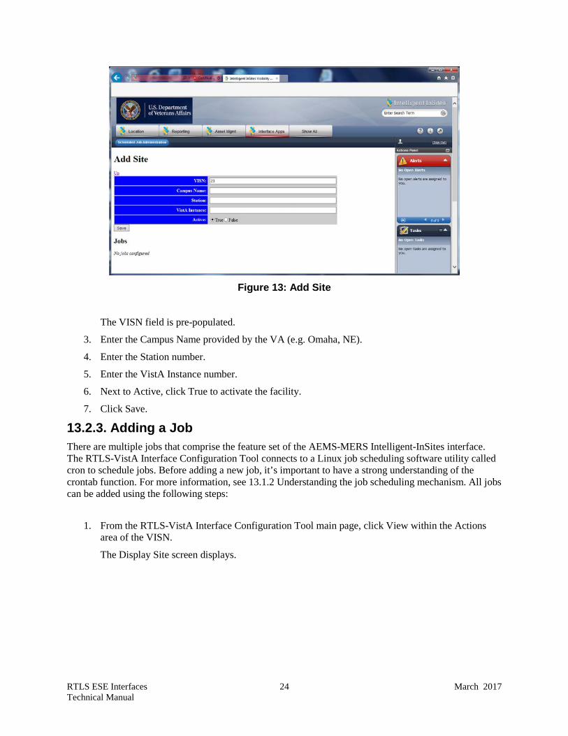
Figure 13: Add Site
The VISN field is pre-populated.
3. Enter the Campus Name provided by the VA (e.g. Omaha, NE).
4. Enter the Station number.
5. Enter the VistA Instance number.
6. Next to Active, click True to activate the facility.
7. Click Save.
13.2.3. Adding a Job There are multiple jobs that comprise the feature set of the AEMS-MERS Intelligent-InSites interface. The RTLS-VistA Interface Configuration Tool connects to a Linux job scheduling software utility called cron to schedule jobs. Before adding a new job, it’s important to have a strong understanding of the crontab function. For more information, see 13.1.2 Understanding the job scheduling mechanism. All jobs can be added using the following steps:
1. From the RTLS-VistA Interface Configuration Tool main page, click View within the Actions
area of the VISN.
The Display Site screen displays.

RTLS ESE Interfaces 25 March 2017 Technical Manual
Figure 14: Display Site
2. Click Add Job
The Add Job screen displays.
Figure 15: Add Job
The Station number is pre-populated.
3. Select the Job type.
RTLS ESE Interfaces 26 March 2017 Technical Manual
4. Enter a description in the Description field.
5. Enter the VistA instance number in the VistA Instance field. The VistA instance number is the first three-digits of the Station number.
6. Enter the Cron schedule in the CronTab field.
7. Next to Active, click True to activate the job.
8. Click Save.
13.3. Managing Existing Jobs The following sections represent tasks necessary for maintaining the AEMS-MERS/RTLS interface jobs.
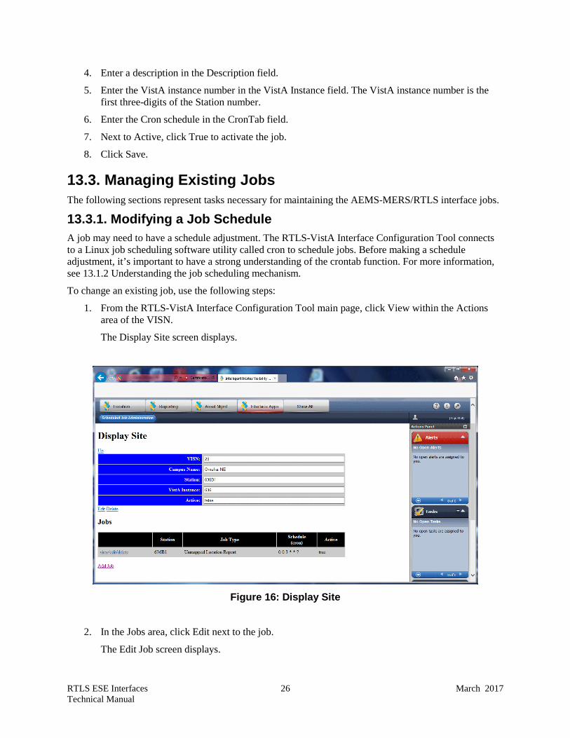
13.3.1. Modifying a Job Schedule A job may need to have a schedule adjustment. The RTLS-VistA Interface Configuration Tool connects to a Linux job scheduling software utility called cron to schedule jobs. Before making a schedule adjustment, it’s important to have a strong understanding of the crontab function. For more information, see 13.1.2 Understanding the job scheduling mechanism.
To change an existing job, use the following steps:
1. From the RTLS-VistA Interface Configuration Tool main page, click View within the Actions area of the VISN.
The Display Site screen displays.
Figure 16: Display Site
2. In the Jobs area, click Edit next to the job.
The Edit Job screen displays.

RTLS ESE Interfaces 27 March 2017 Technical Manual
Figure 17: Edit Job
3. Modify the field(s).
4. Click Save.
13.3.2. Running a Job on Demand On very rare occasions, a job may need to be run on demand. Before running a job on demand, make sure you understand the network implications and associated payload, see Section 13.1.2.3 Scheduling Considerations for more information. To run a job on demand, use the following steps:
1. From the RTLS-VistA Interface Configuration Tool main page, click View within the Actions area of the VISN.
The Display Site screen displays.
2. In the Jobs area, click View next to the job.
The Display Job screen displays.

RTLS ESE Interfaces 28 March 2017 Technical Manual
Figure 18: Display Job
3. Ensure the Active field is set to true.
4. Click Run Now.
A confirmation message is displayed.
13.3.3. Suspending a Job There may be occasions when a job needs to be temporarily suspended (e.g. due to system maintenance). To suspend an active job, use the following steps:
1. From the RTLS-VistA Interface Configuration Tool main page, click View within the Actions area of the VISN.
The Display Site screen displays.
2. In the Jobs area, click Edit next to the job.
The Edit Job screen displays.
RTLS ESE Interfaces 29 March 2017 Technical Manual
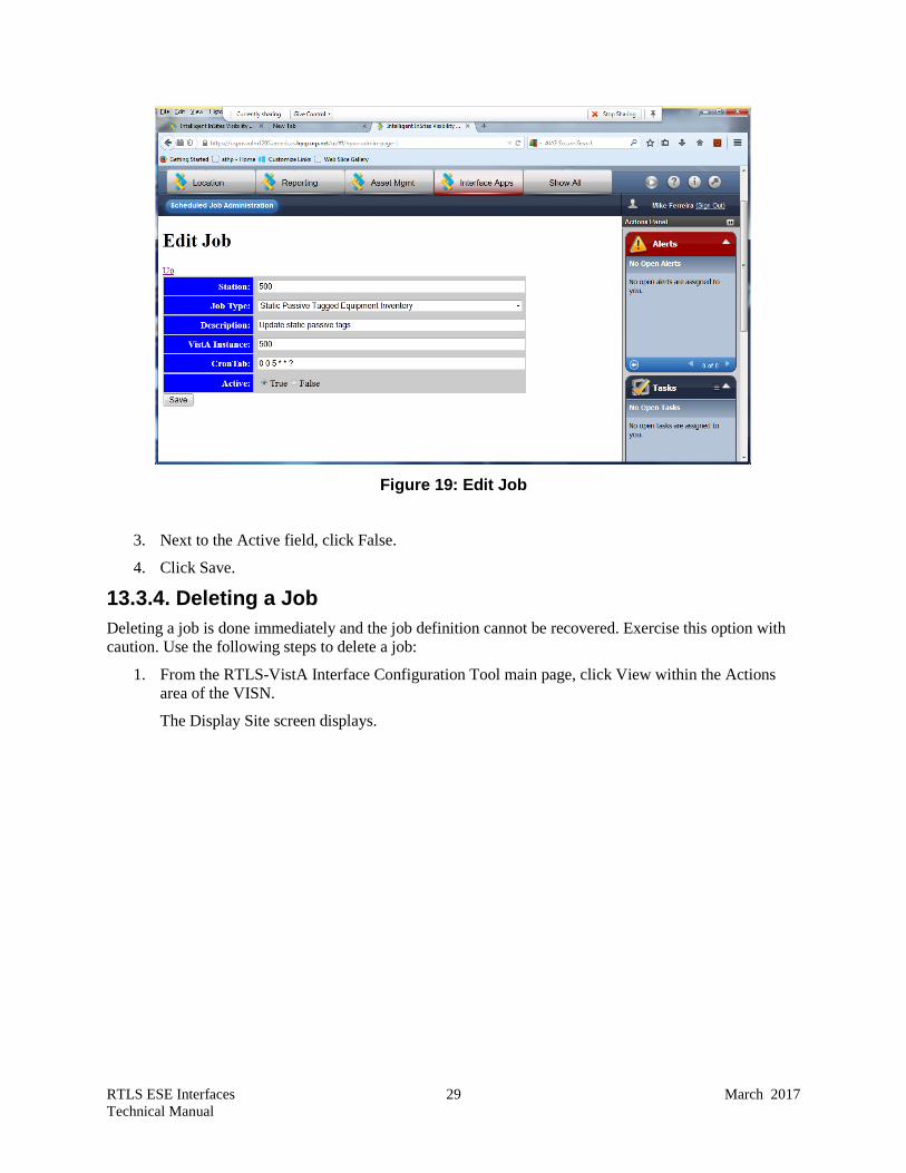
Figure 19: Edit Job
3. Next to the Active field, click False.
4. Click Save.
13.3.4. Deleting a Job Deleting a job is done immediately and the job definition cannot be recovered. Exercise this option with caution. Use the following steps to delete a job:
1. From the RTLS-VistA Interface Configuration Tool main page, click View within the Actions area of the VISN.
The Display Site screen displays.

RTLS ESE Interfaces 30 March 2017 Technical Manual
Figure 20: Display Site
2. In the Jobs area, click Delete next to the job.
The job is deleted.
13.4. Managing an Existing VA Facility Definition The following sections represent tasks necessary for modifying or deleting a VA Facility definition from the RTLS-VistA Interface Configuration Tool.
13.4.1. Modifying a VA Facility Definition A parameter related to the VA Facility definition may need to be changed. To change an existing facility definition, use the following steps:
1. From the RTLS-VistA Interface Configuration Tool main page, click View in the Actions area.
The Display Network screen displays.

RTLS ESE Interfaces 31 March 2017 Technical Manual
Figure 21: Display Network
2. In the Sites area, click Edit next to the site.
The Edit Site screen displays.
Figure 22: Edit Site

RTLS ESE Interfaces 32 March 2017 Technical Manual
3. Change the field(s).
4. Click Save.
13.4.2. Deleting a VA Facility Definition Deleting a VA Facility definition (i.e. Site) from the tool is done immediately and the jobs associated with the facility are also deleted. The VA Facility definition cannot be recovered. Exercise this option with caution. Use the following steps to delete a site:
1. From the RTLS-VistA Interface Configuration Tool main page, click View within the Actions area of the VISN.
The Display Network screen displays.
Figure 23: Display Network
2. In the Sites area, click Delete next to the site.
The site is deleted.

RTLS ESE Interfaces 33 March 2017 Technical Manual
14. Appendix B: Troubleshooting The following sections provide information on potential operational issues within the RTLS system. The content is divided into two main sections based on the underlying technologies employed. The RTLS Interface Applications cover the four interfaces related to VistA, WebLogic, and the Mule ESB flows. The CART-CL/WaveMark Interface section covers the CART-CL/WaveMark interface.
14.1. RTLS Interface Application The RTLS Interface Applications orchestrate specific Mule ESB process flows to support the following functional areas:
• AEMS-MERS Equipment synchronization with RTLS
• GIP Inventory Supply synchronization with WaveMark
• Search of VistA employee data for use within the WaveMark system
• Search of VistA patient demographic data for use within the WaveMark system
14.1.1. Understanding the Log Files The RTLS Interface Applications use a Java logging framework called log4j. The log files are defined in the log4j.properties file and also included below for convenience. The log4j.properties file can be used to configure different logging levels for each RTLS interface component and also to enable and disable logging as needed. The log files capture information about exceptions that arise while running the application.
Log File Description /data/rtls/vistasvcs/{env}/log/rtls.log WebLogic log file. /data/mule/{env}/logs/mule_ee.log Mule ESB log file. /data/mule/{env}/logs/{flowname}.log
The following interfaces have log files:
• AEMS-MERS/Intelligent InSites
• Employee/WaveMark
• Patient/WaveMark
• GIP/WaveMark
Note: In the log file names above, {env} represents an environmental variable set during installation. {flowname} represents the interface job flow name.
14.1.2. Troubleshooting The interfaces employ Mule ESB and the WebLogic-based Vista Service RESTful Web Services. Mule ESB and VistaService capture details of runtime errors in the log4j files. The following table is provided as a reference to possible RTLS Interface Application exceptions.

RTLS ESE Interfaces 34 March 2017 Technical Manual
Interface Issue Possible Cause Solution AEMS-MERS/Intelligent Sites
A scheduled job failed. Network connectivity issues.
Check the AEMS-MERS and Mule ESB log files. Scheduled jobs automatically retry using the same parameters during the next scheduled interval if the scheduler in unable to reach the Mule ESB. The jobs can also be run on demand, but this option should be exercised with extreme caution. See Section 13 Appendix A: RTLS-VistA Interface Configuration Tool for more information.
AEMS-MERS/Intelligent InSites
The Intelligent InSites user interface does not contain expected AEMS-MERS data.
Information is not available from AEMS-MERS or VistaServices encountered an unexpected condition that prevented it from fulfilling the request.
Check the AEMS-MERS log file. The input validation response codes are 404 for resource not found and 500 for all other failures.
AEMS-MERS/Intelligent InSites
Update of a field in AEMS-MERS that contains a trigger for our interface does not get updated in Intelligent InSites.
Communication issue with Mule ESB.
Check the PENDING RTLS EVENTS (#6930) file to see if the missing update exists within the file. The PENDING RTLS EVENTS file introduces a redundancy to save record changes that could not be sent to RTLS when the Mule server is offline for any reason. If the missing update exists in the file, then the MAKE WEB CALL TO MULE TaskMan option is possibly not running, and needs to be restarted. Restart the TaskMan option. If the
RTLS ESE Interfaces 35 March 2017 Technical Manual
Interface Issue Possible Cause Solution option fails again, contact the VistA Administrator.
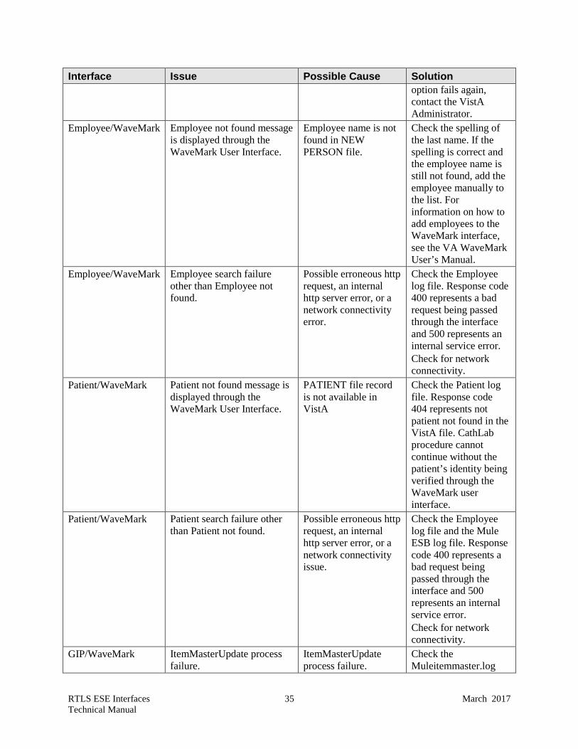
Employee/WaveMark Employee not found message is displayed through the WaveMark User Interface.
Employee name is not found in NEW PERSON file.
Check the spelling of the last name. If the spelling is correct and the employee name is still not found, add the employee manually to the list. For information on how to add employees to the WaveMark interface, see the VA WaveMark User’s Manual.
Employee/WaveMark Employee search failure other than Employee not found.
Possible erroneous http request, an internal http server error, or a network connectivity error.
Check the Employee log file. Response code 400 represents a bad request being passed through the interface and 500 represents an internal service error. Check for network connectivity.
Patient/WaveMark Patient not found message is displayed through the WaveMark User Interface.
PATIENT file record is not available in VistA
Check the Patient log file. Response code 404 represents not patient not found in the VistA file. CathLab procedure cannot continue without the patient’s identity being verified through the WaveMark user interface.
Patient/WaveMark Patient search failure other than Patient not found.
Possible erroneous http request, an internal http server error, or a network connectivity issue.
Check the Employee log file and the Mule ESB log file. Response code 400 represents a bad request being passed through the interface and 500 represents an internal service error. Check for network connectivity.
GIP/WaveMark ItemMasterUpdate process failure.
ItemMasterUpdate process failure.
Check the Muleitemmaster.log

RTLS ESE Interfaces 36 March 2017 Technical Manual
Interface Issue Possible Cause Solution file and the Mule mule_ee.log log file. Response code 500 represents a failure of the ItemMasterUpdate process. The Vista Service rtls.log can provide additional details.
GIP/WaveMark Failure of the OnHandLink processes (i.e. Usage Feed and True Up Feed)
Failure of the OnHandLink processes (i.e. Usage Feed and True Up Feed)
Check the Muleonhandlink.log file and the Mule mule_ee.log file. Any response other than 202 is a failure. Response code 202 represents a successful upload. The Vista Service rtls.log can provide additional details
GIP/WaveMark Failure of the OnHandLink processes (i.e. Usage Feed and True Up Feed)
Record in GENERIC INVENTORY (445) file is locked by another user in GIP.
Check to make sure the record is no longer locked and re-run the feed. Consider re-scheduling the feeds to run beyond normal working hours to reduce the chance of another record locking event. The Vista Service rtls.log can provide additional details on a locked GIP record.
14.2. CART-CL/WaveMark Interface The CART-CL/WaveMark interface allows the WaveMark system to directly pass specific information related to the WaveMark encounter to a pair of SQL Server staging tables created in CART-CL exclusively for this purpose.
14.2.1. Understanding the High Level Operations The scheduler in the WaveMark Interface Engine is responsible for dispatching the CART-CL/WaveMark interface. Once an instance of EncounterLink has been dispatched, it will go through the following high level operations:
1. Query the WaveMark Engine for all encounters that have not been sent to CART-CL. 2. Translate the data into a series of SQL inserts.

RTLS ESE Interfaces 37 March 2017 Technical Manual
3. Establish a JDBC connection to the CART-CL CART_RTLS database. 4. Send the data to CART-CL in the form of SQL inserts. WaveMark’s EncounterLink (i.e.
ELCART0001) is aware of the status of all interface operations. In the event that data fails to be sent from WaveMark to CART-CL, EncounterLink will ensure that the dropped/failed encounter is resent.
5. Commit the data.
14.2.2. Troubleshooting The connection between CART-CL and WaveMark is initiated by the WaveMark system. Errors are logged in the WaveMark Interface Engine user interface (UI). The WaveMark Interface Engine UI provides information about the interface that generated the error, a description of the error, a timestamp for when the error occurred, and a severity.
Issue Possible Cause Solution Connection between WaveMark components is unavailable due to loss of power or connectivity.
Failure to query the WaveMark engine.
A retry mechanism is implemented and controlled using a backend settings file. The query to the WaveMark Engine will be attempted three times. If all three attempts fail, an error is logged. Escalate the issue as appropriate.
Connection between WaveMark and CART-CL is unavailable.
Failure to establish a JDBC connection to CART-CL.
Check the WaveMark Interface Engine user interface for a listing of the error, a description of the error, and the date and time the error occurred. Escalate the issue as appropriate.
Connection between WaveMark and CART-CL is unavailable due to loss of power or connectivity.
Failure to send the data to CART-CL.
All sent encounters during this session are rolled back, and an error is logged. Check the WaveMark Interface Engine user interface for a listing of the error, a description of the error, and the date and time the error occurred. Escalate the issue as appropriate.
14.3. Frequently Asked Questions (FAQ) For a list of Frequently Asked Questions, see the RTLS ESE Installation Guide.