Embed Size (px)
Citation preview

Presented by:
Stantec &
Golder Associates
February 2, 2016
Department of National Defence B-Jetty Reconstruction CFB Esquimalt, BC

Agenda
1 B-Jetty Project Background
2 Distinguishing Project Features
3 Structural Schemes Considered
4 Design Considerations
5 Structural Pile Considerations
6 Analysis
7 Dredging and Soil Remediation

VICTORIA
ESQUIMALT

Project Background
DND B-Jetty Reconstruction Stantec I Golder Associates
Existing B-Jetty
• Finger pier constructed in early 1940’s • Reconstructed in 1956 • Timber pile/pile cap structure with pre- cast
concrete deck panels • Original design vessel – 2000 tons • About 190 m long and 18 m wide • Fixed crane

DND B-Jetty Reconstruction Stantec I Golder Associates
B-Jetty Replacement Project • To accommodate the next class of offshore
patrol vessels, frigates and supply vessels (JSS, AOPS, CSC, Subs)
• Design vessel - 20,000 Tonnes displacement • Finger pier About 270 m long and 26 m wide • Rail mounted crane • Services tunnel around jetty perimeter
“Stub” section to align with future A-Jetty replacement project

A JETTY
B JETTY
C JETTY
DRYDOCK

A JETTY
B JETTY
C JETTY
DRYDOCK

Distinguishing Project Features

DND B-Jetty Reconstruction Stantec I Golder Associates
Geotechnical Field Investigations
• Geophysical and geotechnical investigations were undertaken to obtain information on subsurface conditions
• Geophysical investigations consisted of multi-beam (high resolution) bathymetry survey and sub-bottom profiling of an area comprising both B- and A-Jetties
• Geotechnical investigations consisted of cone penetration tests and samples boreholes with rock coring and sampling to depths varying from 10 to 20 m
• Geophysical televiewer surveys were also carried out in the rock core holes

DND B-Jetty Reconstruction Stantec I Golder Associates
Geotechnical Results – Geophysical Surveys (Non-intrusive)
Inferred Glacial Till/Bedrock Surface
Inferred Seabed Surface

DND B-Jetty Reconstruction Stantec I Golder Associates
Geotechnical Borehole Investigation
Area-3
Area-1
Area-2

DND B-Jetty Reconstruction Stantec I Golder Associates
Geotechnical Subsurface Conditions
• Shallow bedrock near shore • Bedrock slopes sharply down in seaward direction • Marine sediments vary from non-existent near
shore to 10 m thick offshore • Marine sediments are underlain by Victoria Clay
to depths in excess of 70 m from seabed • Clay underlain by thin till layer and bedrock • Bedrock quality varies with severe fracturing/
jointing and low intact strength in upper 1 – 9 m

DND B-Jetty Reconstruction Stantec I Golder Associates
Soil Stratigraphy - B Jetty

DND B-Jetty Reconstruction Stantec I Golder Associates
Geotechnical Shear Strength Profile Victoria Clay and Marine Sediments

DND B-Jetty Reconstruction Stantec I Golder Associates
Earthquakes
DND B-Jetty Reconstruction Stantec I Golder Associates
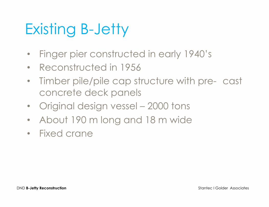
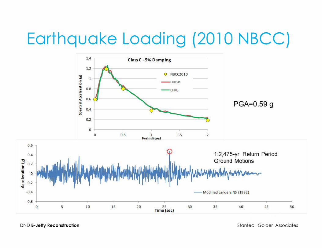
Earthquake Loading (2010 NBCC)

DND B-Jetty Reconstruction Stantec I Golder Associates
Earthquake Loading (2010 NBCC)

DND B-Jetty Reconstruction Stantec I Golder Associates
Tsunami
Cause and Effects of a Tsunami
• M9 megathrust earthquake • Mike 21 modelling package • Water level rise 1.6 m to 1.8 m • Time of arrival after EQ ~ 90 minutes • Current speed ~ 6 m/s • Wave hits broadside to finger pier • Run-up

DND B-Jetty Reconstruction Stantec I Golder Associates
Tsunami

DND B-Jetty Reconstruction Stantec I Golder Associates
Tsunami B Jetty
0 m 50 m 100 m
NAD83 UTM Zone 10 Projection

DND B-Jetty Reconstruction Stantec I Golder Associates
Tsunami

DND B-Jetty Reconstruction Stantec I Golder Associates
Tsunami

DND B-Jetty Reconstruction Stantec I Golder Associates
Tsunami
Computed Run-Up (Shaded)

Structural Schemes Considered

DND B-Jetty Reconstruction Stantec I Golder Associates
Structural Schemes Steel Sheet Piles and Concrete Caissons • Apply sustained loads to weak and compressible
overburden soils • Would result in large, on-going total and
differential settlements • Not acceptable Steel Pipe Piles • Vertical loads transferred to bedrock • No settlement • Pile lengths vary from less than 5 m near shore to
more than 90 m at the seaward end

DND B-Jetty Reconstruction Stantec I Golder Associates
Preferred Structural Scheme
Steel Pipe Piles • Rock anchored steel pipe piles • Reinforced concrete pile caps, support beams
and deck • But still a significant challenge to construct due to
thick overburden and deep bedrock at seaward end

Design Considerations

DND B-Jetty Reconstruction Stantec I Golder Associates
Geotechnical • Shallow bedrock at shoreward end, very deep
bedrock at seaward end • Bedrock quality varies with severe fracturing/
jointing and low intact strength in upper 1 – 9 m
Vessels & Operational Loads • Water depth 11.5 m max (varies) • 20,000 Tonnes Displacement max • Deck live load – 30 kPa • Rail mounted crane • Berthing loads, Mooring loads (60 knots)

DND B-Jetty Reconstruction Stantec I Golder Associates
Earthquakes • 2,475 year return period (NBCC) • Importance Factor 1.5 (Post-Disaster) • Analyses based on both National Building Code
of Canada and Canadian Highway Bridge Design Code
Tsunami • Current speed ~ 6 m/s • Wave hits broadside to finger pier • Current force on berthed Joint Supply Ship (JSS) • Governs over earthquakes loads

Structural Pile Configurations

DND B-Jetty Reconstruction Stantec I Golder Associates
Concept 1
• Mix of battered and vertical piles • Battered piles provide lateral
bracing • Challenge to install in deep
bedrock zones

DND B-Jetty Reconstruction Stantec I Golder Associates
Concept 2
• All vertical piles • More lateral movement under high
loads (EQ, Tsunami) than battered piles
• Challenge to install in deep bedrock zones – but less than for battered piles

DND B-Jetty Reconstruction Stantec I Golder Associates
Preferred Configuration • Concept 2 – All Vertical piles • Main Consideration - Constructability

Analysis

Analysis – SAP 2000
Classic Line Diagram
Solid Surface Diagram

DND B-Jetty Reconstruction Stantec I Golder Associates
Displacement (Tsunami)
SOIL INTERACTION
TSUNAMI FORCE
LINEAR SPRINGS AT DISCRETE POINTS, BUT NON-LINEAR ALONG THE LENGTH OF PILE
Governing load combination generally due to Tsunami Forces

DND B-Jetty Reconstruction Stantec I Golder Associates
Jetty Deflection – Tsunami West to East (Incoming)
TSUNAMI
180 mm

DND B-Jetty Reconstruction Stantec I Golder Associates
Required: • 1067 mm dia, rock anchored, concrete filled pipe piles
• Post-tensioned longitudinal beams and deck
Stresses - Tsunami

Dredging and Soil Remediation

DND B-Jetty Reconstruction Stantec I Golder Associates
Dredging and Soil Remediation Contaminated Soil Remediation • Significant effort to remove contaminated harbor
sediment • Remediated areas to be capped with a 300 mm
thick layer of sand (Residual Management Cover). • RMS Cover 14,000 m2
Soft Sediment Dredging • For soil remediation and for water depth at berths • Estimated Quantity 40,000 m3
• All dredged material to be barged to offsite offload location for land disposal

DND B-Jetty Reconstruction Stantec I Golder Associates
Dredging and Soil Remediation
Bedrock Dredging • For infrastructure installation • For water depth at vessel berths • For rock removal adjacent to Future A-Jetty location • Estimated Quantity 6,500 m3

Limits of Dredging
NON-REMEDIATED
REMEDIATED

DND B-Jetty Reconstruction Stantec I Golder Associates
Limits of Dredging
SOFT SEDIMENT DREDGING TO BEDROCK
SOFT SEDIMENT DREDGING TO DEPTH (REMEDIATED)
SED TO BR
SED TO BR
-‐13.9 m
-‐13.7 m
-‐12.2 m
-‐15 m
SLOPE UP TO -‐4 m REMOVE 1 TO 2.2 m

DND B-Jetty Reconstruction Stantec I Golder Associates
Limits of Dredging
SOFT SEDIMENT DREDGING TO DEPTH (NON-‐REMEDIATED)
BEDROCK DREDGING
-‐13.4 m
-‐11.9 m
-‐13.7 m
-‐12.2 m
DND B-Jetty Reconstruction Stantec I Golder Associates
Bedrock Dredging/Blasting
• Bedrock removal both onshore and within the harbor, required for infrastructure installation and for water depth at vessel berths
• Must be carried out near existing historic structures including buildings, quay wall and drydock
• Mitigating effects on local marine mammals are also an important consideration for the blasting program
• Blasting program includes low yield charges, bubble curtain, marine life exclusion zone

DND B-Jetty Reconstruction Stantec I Golder Associates

Questions?