Embed Size (px)
Citation preview
HENRY WARD
COMMISSIONER OF HIGHWAYS
COMMONWEALTH OF KENTUCKY
DEPARTMENT OF HIGHWAYS FRANKFORT
March 1 , 1963
MEMO TO: A, 0, Neiser Assistant State Highway Engineer
ADDRESS REPLY TO DEPARTMENT OF HIGHWAYS
MATERIALS RESEARCH LABORATORY
132 GRAHAM AVENUE
LEXINGTON 29, KENTUCKY
D , l.7, c ,2,8'
One of the major problems confronting highway departments today is the rapid deterioration of reinforced concrete bridge decks, The widespread use of de-icing chemicals has accelerated the occurrence of concrete failures.
For some years the Department, particularly the Maintenance Division, has been experimenting with various repair and coating systems for bridge decks, The Division of Research has participated in much of this work, Messrs, S, T. Collier, D. H. Sawyer, and Milton Evans, Jr,, all former research engineers, have participated in either the laboratory or field evaluation of concrete durability,
We have made a concerted effort in the attached report, "Concrete Bridge Decks: Deterioration, Coatings, and Repairs," by Mr, J, H, Havens9 Assistant Director of Research, and myself, to combine at least some data for all of the structures that have been repaired or analyzed for which we have records, As much repair or construction data as could be collected in the time available have been included, Undoubtedly, there have been some omissions, and we welcome you, or other members of the Research Committee, to contribute whatever additional information you may have.
Performance data of repaired sections are somewhat limited, particularly for recent installations, Considerable use has been made of photographs in showing procedures and performance, From the number of structures discussed, you may conclude that we are having some right serious problems with the weather durability of bridge decks -- I think that we are -- and, from recent surveys in Missouri, Illinois, Wisconsin, Iowa and New York, the problem appears to be rather widespread,
A, 0, Neiser - 2 - March 1 , 1 963
You will note in the report that we have outlined several apparently usable methods for repair and protection of existing concrete bridge decks. The solution, of course, is to eliminate the sources of trouble rather than to cover them up.
I am of the opinion that air-entrained (4% to 7%), properly designed, and finished concrete will resist the action of weather, and de-icing chemicals. I have discussed an innovation in the design and finishing procedures of the deck slabs with Mr. E. D. Smith, Director of Bridges, which I believe will vastly improve the durability of the concrete, It would require a joint at the face of the curb and the mounting of a fixed, steel section for a full-width (2-lane structure), deckfinishing machine to operate over. An angle section could be used with one leg of the angle set to the grade of the curb line for the screed to work over, The wheels of·the finishing machine·eould operate on the other leg of the angle, This arrangement would eliminate the need for removal of the screed templates from the fresh concrete , A very high percentage of the template grooves show up in the weathered concrete and frequently provide channels for deck disintegration, Curb and walk finishing under our present design has required the workmen to operate from the freshly placed deck concrete, with resultant damage to the deck itself , Loss of entrained air, laitance, and filling of foot prints with very wet mortar has been observed,
It appears that the problem is critical enough to consider the structural requirements necessary to pass a reasonable finishing train over the bridge decks. Of course, the pouring pattern would have to be revised on some continuous structures, but I believe that these items can be resolved in the interest of providing sound, durable concrete. I believe that excellent ready-mixed concrete can be provided through close i nspection and control,
WBD:dl Enc.
· cc: Research Cornrni ttee Members Bureau of Public Roads (3)
subrni t ted,
W: B. Tirake Director of Research
Commonwealth of Kentucky Department of Highways
CONCRETE, BRIDGE DECKS: DETERIORATION, COATINGS AND REPAIRS
by
Jas " H. Havens Assistant Director of Research
and
Wo B. Drake Director of Research
Highway Materials Research Laboratory Lexington, Kentucky
February, 1963
TABLE OF CONTENTS Page
INTRODUCTION. o () a .. .. .. .. . o .. a .. .. o a o .. ., .. .. ... . "' ... ., ••••• o .. o o • o •. .. .. " • o • o .. o1 .. o o .. 1
The Freeze-Thaw Mechanism
Concreting Practices
Occurrence of Cracks in New Decks
Corrosion of Reinforcing Steel
Protective Coatings
Repairs
REINFORCED CONCRETE BRIDGE-DECK REPAIRS AND PROTECTIVE TREATMENTS .. . .. . ., •••• " ••••• o •••• " •••• o ••• , .. . a •••• a, • 13
Irvine s. Cobb Bridge
Balls Fork Bridge
Russell Fork Bridge
Railroad Overpass, Beuchel
Clark Memorial Bridge
Ashland-Coal Grove Bridge
St. Catherine ' s Street Bridge
Salt River Bridge (Twin)
Price Pike Bridges (Twin)
Twin Bridges over Pruitt Road
Lake Cumberland Bridge
Southern Railroad Overpass
Five, Franklin County, Bridges
Owensboro Bridge
Big Eddy Road Bridge
Kentucky River Bridge
Clays Ferry Bridge
HEATING BRIDGE DECKS o o o o o -o c o o o o o o o o eo o o �> o a o o eo e o o o o o o o DGO tl o 45
S�Y Q o o o Q a e o o e o o o o o o .. e o o o " o o o e o o o " o e o o ..o o o e o o o o o o o o o o o o o o o 4 7
INTRODUCTION
This report is not wholly a culmination of a planned or pro�
grammed research project , It is a historical account of damage sustained
by both new and old concrete bridge-decks -- through freeze-thaw, salt
action, etc, -- and of some expedient repairs which have been effected ,
The problem of durability in concrete bridge-decks has become increas
ingly critical during the past ten years or so and is now a major con
cern to highway engineers throughout the northe;rn tier of states. While
there is not yet a concerted agreement in regard to the cause of the
trouble , relief is being sought through improved construction practices,
air-entrainment, and protective coatings of various kinds , Similarly,
relief from perpetual maintenance or complete replacement of existing
bridge decks is being sought through improved methods for making repairs ,
The performance of individual slabs in a deck is sometimes
markedly different from that of a nearby slabj and, even within a parti
cular slab, only one corner or one end may be· affected , This signifies
poor concreting practices , The concrete sustaining damage was undoubt
edly over-watered, over-worked , de-aired , and segregated , The proper
placement of deck concrete is perhaps the more serious aspect of tlle
problem than the repair, because improper placement automatically incurs
a premature maintenance liability, Of course, as the need for repairs
arises in due time, reliable methods of repair should be employed , It
is in this latter respect that the repair experiences recorded in this
report are expected to be the most fruitful ,
� 2 �
None of the damaged decks which have been observed thus far
has shown any evidence of overloading by traffic (adjudged by the
absence of any checker�board crack�pattern on the underneath side of the
deck); the trouble seems to be attributable almost entirely to weathering ;
and the weathering invariably seeks out and attacks the poorest concrete
often revealing the mistakes made by the workmen and their attempts to
hide them,
Improper drainage of the deck and gutter can be one of the con�
tributing factors to damage , Even slabs and gutters sometimes have
"bird�baths" in them , Cinders, sand, road-debris, and snow sometimes
impound water and prevent drying , Such areas are exposed to water and
moisture beyond their normal time,, and damage is often associated with
these conditions ,
The Freeze�Thaw Mechanism
In many respects , the mechanics of freeze-thaw damage to con�
crete is similar to the mechanism which causes a water pipe to freeze
and burst , The density of water at 0°C is 0 , 9998 gms/cm3 whereas the
density of ice at o•c is 0 ,917 gms/cm3 , There is, therefore, an increase
of approximately nine percent in volume when water freezes , Likewise,
if a vessel is completely filled with water at o•c and is sealed and
if the water therein is frozen. the vessel must yield or dilate as much
as nine percent by volume or else it wil l rupture , However, if the
vessel were filled with water to 91 , 7 percent of its volume, the volume
of ice produced would just equal the volume of the vessel, and no dilation
- 3 �
of the vessel would occur , Moreover, if the water is un-restrained or
fails to fill the vessel upon freezing and exerts no dilation pressure
on the vessel, it freezes normally at 32°F; however, if the vessel
offers restraint, each 1000 psi of restraining pressure lowers the
freezing point of the water l°F , The final freezing point of the water
thus provides a measure of the dilation pressure , Final freezing points
of 26°F have been recorded on laboratory specimens of concrete* , This
is equivalent to an active pressure of 5000 or 6000 psi ,
If a specimen of concrete absorbs 10 percent water by volume
and if this amount of water completely fills the voids in the concrete ,
the increase in volume of the specimen, upon freezing, would be approxi-
mately 0 , 9 percent , This amount of dilation would, in all likelihood,
cause the concrete to rupture , Laboratory tests have demonstrated
repeatedly that freeze-thaw damage is related, to water absorption and
to the degree of saturation (absorption in relation to porosity) , Dry
concrete can not be affected in this way; and it is fortunate indeed
for the welfare of most exposed concrete and masonry structures that
nature provides frequent periods of drying , Thus, the duration of
wetting, either preceeding or attendant to the onset of freezing, may
largely determine the amount of damage incurred , Likewise, the resis·
tance of concrete to freeze-thaw may be viewed wholly in terms of its
* "Thermal Analysis of the Freeze-Thaw Mechanisms in Concrete," by Jas , rl, Havens , Bulletin No , 59, Engineering Experiment Station, University of Kentucky , MarCh 1961 ,
� 4 �
resistance to saturation �- that is, the duration of wetting in compari
son to the time tbat it takes for the concrete to become critically
saturated,
Surface and shallow damage; sometimes called "frost�damage" or
"scaling", is more prominent than deep ;,damage; and this is attributable
to the fact that there is greater opportunity and likelihood that critical
saturation and freezing will occur near the surface; and this is so even
during very brief periods of wetting if the concrete near the surface is
porous and receptive to water,
Problems of durability of concrete in bridge decks and the effects
thereon of de-icing salts in Kentucky parallel those experienced by neigh
boring states to the north and elsewhere , There is some possibility,
perhaps, that Kentucky weather conditions are the more adverse - � that
is, there may be more freezes by night and more thaws by day than the
northern states experience , In any case, long periods of wetting, as might
result from snow and ice melting during day-time warming or due to de-icer
salts, are conducive to saturation; and the periodic freezing attendant, __
thereto is much more damaging than a continuous , deep freeze , As an example ,
trucking companies have a rather serious problem in concrete durability at
their loading docks where trucks carry in snow and slush from the roads
and stand and drip ,
There have been discussions , here and elsewhere , contrasting the
durability of rather old bridge decks and the, comparatively poor durability
of many new ones , Similarly. c�ntrasts have been recognized between the
performance of deck concrete and pavement concrete abutting thereto ,
� 5 �
In the same way, account has been given to the fact that recent ex�
periences of poor durabi lity parallel the more abundant use of de-icer
salts* , A recent account of experiences elsewhere is available in
Bulletin 323, HRB, a symposium on "Effects of De-icing Chemicals on
Structures," 1962 ,
Concreting Practices
In addition to the fact that bridge decks may undergo·.more
freezing cycles than pavements on the ground, there is a growing sus
picion that concrete construction and finishing practices on bridge
decks, in many instances , have permitted too much manipulation of the
concrete by the workmen during its placement •· in other words , where
hand�screeding and finishing have been permitted, there has been a
tendency for the workmen to spread-out a lot of concrete, vibrate it ,
walk through it, trample it, and then to work�up enough laitance to fill
in all of the boot-holes, low places, and to achieve a finish · · this
procedure undoubtedly draws unwanted laitance to the top, dissipate�
the air, and invites scaling , The laitance is merely a thin, watery
'mortar, and it remains very porous and absorptive after the concrete has
set , These practices are illustrated in Figs , 1, 2 and 3 , The Depart�
ments Standard Specification disclosure regarding the placement of deck
concrete follows:
* First widespread use of rock salt in the Louisville area was in 1946� 1 947 ; See Annual Report of the Department of Highways, April , 1 946 to March, 194 7 , p , 99,

Fig, 1, Broadway Bridge, North-South Expressway, Louisville; I-65-6(6)134; June-July, 1960.
Fig. 2, Sequence to Fig. 1, Above.
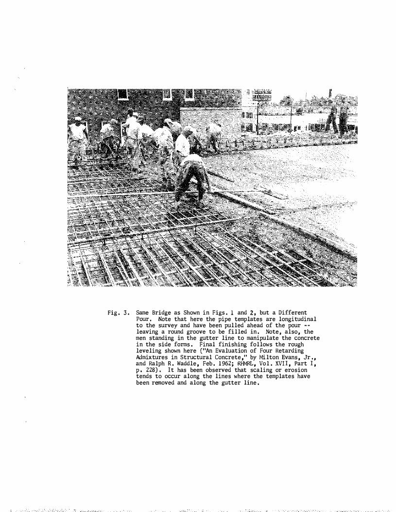
Fig. 3, Same Bridge as Shown in Figs. 1 and 2, but a Different Pour. Note that here the pipe templates are longitudinal to the survey and have been pulled ahead of the pour -
leaving a round groove to be filled in. Note, also, the men standing in the gutter line to manipulate the concrete in the side forms. Final finishing follows the rough leveling shown here ("An Evaluation of Four Retarding Admixtures in Structural Concrete," by Milton Evans, Jr., and Ralph R. Waddle, Feb. 1962; RHMRL, Vol. XVII, Part I, p. 228). It has been observed that scaling or erosion tends to occur along the lines where the templates have been removed and along the gutter line.

- 6 -
5 ,4 , 3-C�S-b , Before concrete for the floor is placed, the Contractor shall provide, at his own expense, metal templates, metal template supports , and straight edges of an approved type which shall be used as hereinafter specified , The metal template supports shall be bolts or other approved types of support which may be lengthened or shortened to adjust template to grade ,
The metal templates shall be rigidly set to the typical crosssection of the bridge floor and shall be placed on the template supports so that the top of the templates will be flush with the finished elevation of the concrete, Templates shall be placed not more than eight feet apart, unless otherwise permitted , and at right angles to the center line of survey, and shall be supported at such intervals as will prevent any sag,
Concrete shall then be deposited between these templates to their full height and compacted , Consolidation of the concrete shall be accomplished by means of internal vibrators and by simultaneous supplementary spading along the forms , I t is distinctly understood that spading will be required in addition to the vibrating to insure against the formation of honeycomb, voids, and air pockets against the forms , The types of vibrators used and the methods employed in vibrating shall be as set out in Article 5 , 6 ,3-C , The consolidation of the concrete shall be continued until contact between the reinforcing steel and the concrete is assured and until the mortar flushes to the top surface ,
Immediately following the consolidation of the concrete, the surface shall be struck o££ to the finished elevation by means of a template screed of rigid construction until a satisfactory surface has been obtained , The metal templates shall be removed prior to the initial set of the concrete, and the groove in the concrete shall be satisfactorily eliminated, *
Figure 4 illustrates a more mechanized operation which eliminated
some of the interferences of the workmen, Deck concrete which is placed
in the same way that pavement concrete is placed would be less likely to
need a protective coating ,
Kentucky

Fig, 4. 1·64·4(8)54; Eastbound Bridge over Kentucky River, Franklin County, October, 1962, Full-width, vibrating screed rides on pipe templates set longitudinally about one foot from the curb wall. Note workmen standing in the gutter on each side. Set-retarding admixture (Sika's Plastiment) used in concrete on warm days. Note: A vibrating screed was used about two years previously on the Veach Dale Interchange Bridge, I-64, near Shelbyville (Sta, 990+00). Also, present plans provide for the use of a Rex finisher on the Louisville-Jeffersonville Bridge (I-65),
- 7 -
Occurrence of Cracks in New Deck s '
Nonnal ly,. concrete expands slightly during the early stages of
hydration and then begins to shrink , The latter phenomenon i s attributed
to self�dessication -- that is, the fact that the cement uses up internal
or free water, Premature drying , likewise, causes severe shrinkage before
the concrete has developed sufficient tensile strength to resist contra
tive forces , Very fine, mesh-like cracks may occur before the final
finishing of the concrete and be unwittingly covered over with laitance,
or they may occur before the curing blanket is applied , Such cracks
inevitably lead to spalling , These cracks are not as likely to occur
on the bottom of slabs or at fonned�surfaces inasmuch as the forms tend
to prevent drying,
A random crack pattern in the bottom surface of a deck can also
signify drying shrinkage or movement of the forms , Concrete which dries
prematurely or which is consol idated and is beginning to set is quite
friable and is easily broken,
Cracks which occur in a systematic pattern, Le, transversely,
or diagonally, may be attributed to flexure or to unifonn shrinkage ,
Corrosion of Reinforcing Steel
Although corrosion of reinforcing steel does occur at some stage:
in the deterioration of concrete decks, it is not known definitely whether
it is a cause or an effect , Perhaps in some instances it may be a cause
particularly so if the steel is inadequately covered and if moisture
and salts are accessible to it , Fine cracks and�rust stains appear over

Fig. 5. Tell-Tale Signs of Cracks {Efforescence) in Comparatively New Deck (State Route 8, Bracken County, Sept. 3, 1957); Cracks Were Sealed in Fall of 1959; Sika Epoxy Bonding Compound.
Fig. 6, Early Cracking in Curb-Section; State Route 8, Bracken County, Sept. 3, 1957,
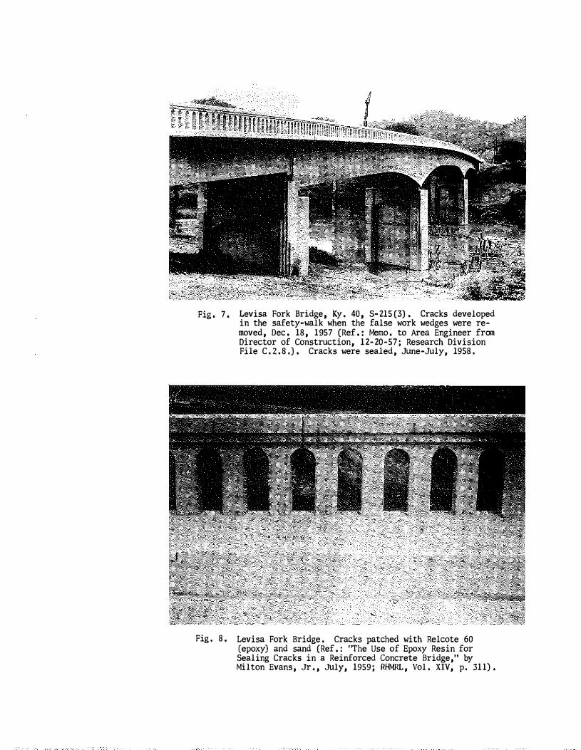
Fig. 7.
Fig. 8.
Levisa Fork Bridge, Ky. 40, S-215(3), Cracks developed in the safety-walk when the false work wedges were re
moved, Dec. 18, 1957 (Ref.: Memo. to Area Engineer from Director of Construction, 12-20-57; Research Division File C,2,8,), Cracks were sealed, June-July, 1958,
Levisa Fork Bridge. Cracks patched with Relcote 60 (epoxy) and sand (Ref.: '�he Use of Epoxy Resin for Sealing Cracks in a Reinforced Concrete Bridge," by Milton Evans, Jr., July, 1959; RHMRL , Vol, XIV, p. 311).
� 8 �
the l ines of steel as tell�tale signs of reaction, Spalling progresses
from these point s ,
Shrinkage cracks in the deck and over�stressing undou�tedly con
tribute to loss of bond between the steel and concrete and permits the
ingress of water and other corrosive agents , The volume of rust pro•
duced is more than 10 times greater than the volume of metal involved ,
Protective Coatings
A committee of experts recently stated : "Wel l�designed con�
crete structures made with top quality, well-consolidates!, air-entrained
concrete using durable aggregates have l ittle need for a protective coat
ing ,"* Nevertheless, coatings may eventually become a rather routine
practice as a further assurance of durability and protection against
de-icer salts , In the past, perhaps numerous bridge decks have been over�
laid with bituminous concrete -- either in conjunction with roadway
resurfacing or as a means of hiding and protecting an unsightly, dete·
riorated deck , U�ortunately, the Department"s records of this kind of
treatment are not adequate for any kind of analysis in this regard ,
However, current thinking here , as wel l as elsewhere , reflects some
suspicion that ordinary, bituminous resurfacing (without special priming)
may actually aggravate the deterioration, and this seems to be a definite
* "Durability of Concrete in Service , " ACI Committee 201, Journal of the American Concrete Institute , December, 1962 ,
� 9 �
possibility if the overlay leaks or otherwise entraps water and hinders
drainage and drying , Because of this , and for other reasons , it seems
wise to regard sealants or coatings with some caution inasmuch as any
kind of coating which merely retards the intrusion of water (breathing
type coatings) may likewise and subsequently retard drying, While there
is perhaps some justification to disdain the use of coatings altogether
on new concrete, they are at least seemingly necessary for the eventual
welfare of the structure and more especially so in the repair and pro
tection of existing, deteriorating decks ,
It has been pointed out by others (ACI , �· �,) that a
breathing-type coating may lead to an accumulation of,
salts beneath the
surface and to aggravate scaling, It might be argued in a similar way
that moisture from the interior of the concrete may condense and
collect beneath an impermeable coating when the exterior temperature
is falling; and, upon freezing, this too could lead to rupture of the
coating and to scaling , Complete sealing of concrete hardly seems
attainable; and , even if it were attainable, it would be necessary to
eliminate all moisture from the interior of the concrete before doing
so, Therefore, from a practical point of view, the most logical re
course would be to use an impervious coating on only those surfaces
directly exposed to moisture and to leave all others free to dry,
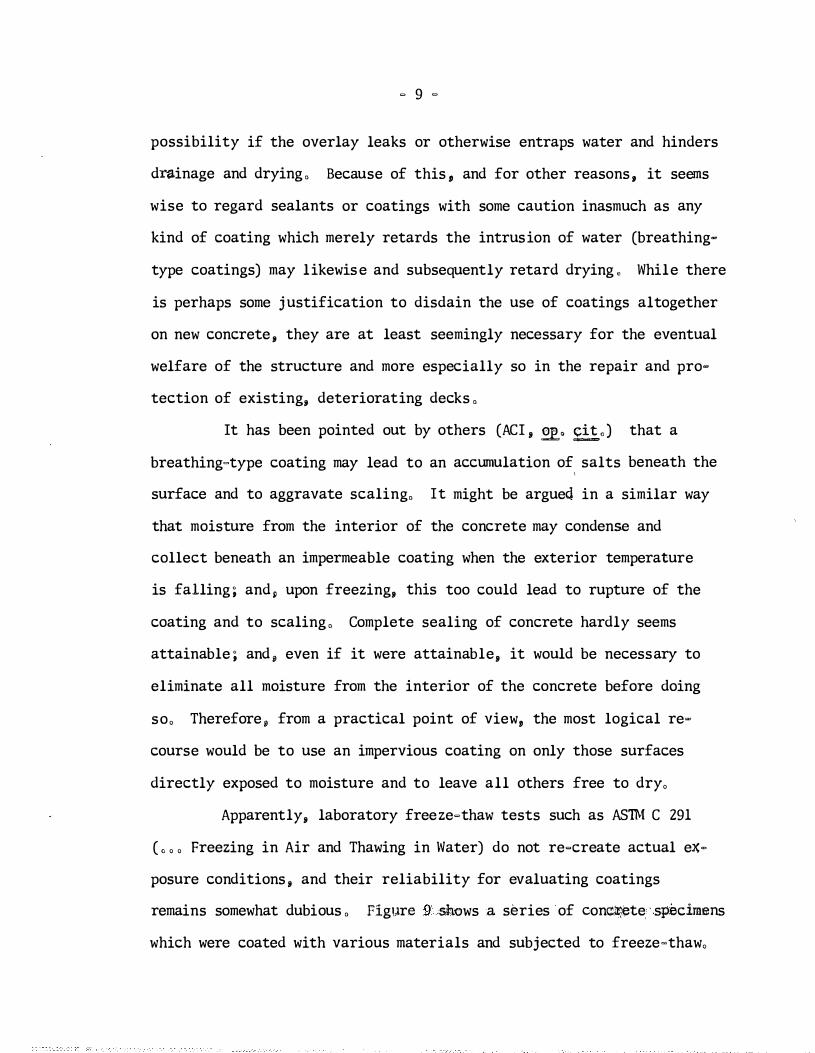
Apparently, laboratory freeze�thaw tests such as ASTM C 291
( , , , Freezing in Air and Thawing in Water) do not re-create actual ex
posure conditions , and their reliability for evaluating coatings
remains somewhat dubious , Figure 9' mows a series of concil)ete- specinums
which were coated with various materials and subjected to freeze-thaw,
Fig. 9. Concrete Beams, 3x4xl6 in.; Cured, Air-Dried, and Coated; f-rozen in Air, Thawed in Water; Specimen No. 1, One Coat ��yer 402, Amine-Cured Epoxy (2-component); No. 2, Same as No. 1 (2 Coats); No. 3, Same as No. 1 (3 Coats); No. 4, Meyer 402-1, Cured with Modified Amine (1 Coat); No. 5, Same as No. 4 (2 Coats); No, 6, Same as No. 4 (3 Coats; No. 7, Meyer 401, Filled Epoxy-Amine Paste (Also Used for Caulking Cracks, Salt River Bridge); No. 8 and No. 9, George W. Whitesides; 56-E-2, Polystyrene; No. 10 and No. 11, Control Specimens (Uncoated). Control Spec�nens sustained 562 cycles ofF & T; 4, 5, and 7 sustained 865 to 900 cycles; all others were approximately equal to or inferior to the Control Specimens of additional series (Not Shown), only Guardkote 140 and other thick-build coatings exceeded the durability of the Control Specimens. (July-August, 1960)

� 10 �
Figure 10 shows a series of concrete piers (Green River
Bridge , US 62, at Rockport) which were completely encapsulated with an
epoxy tar resin (Poxitar) , The surfaces,of the concrete were pervaded
with map cracks , The coating will undoubtedly prevent rain from getting
into the concrete, but it wil l not permit any moisture that might come
up into the pier from the ground to escape , This could eventually lead
to serious trouble, but only the passing of time will prove the worth of
the treatment ,
About 1955, there was some hope that silicone oils dissolved
in naptha or kerosene would prove to be an effective water�repellant ,
Silicone oils, like ordinary lubricating oil� do repel water when
coated onto a porous surface (by negative capil larity) and yet permit
water vapor to move freely � � both inwardly and outwardly , This type
of coating is the ultimate, breathing type of coating , Used engine
oil, paraffin, greases, etc , would provide such action; calcium
stereates and oleates (long used in masonry mortars) are also effective ,
It seems , however, that organic oils and greases tend to oxidize with
the passing of time and loose their oily qualities, but there was hope
that silicones would be everlasting in this respect ,
There is now some suspicion that water under slight pressure
may force into the surface pores far enough to reach the untreated
depths �� after which inner capil lary suction would draw in the surface
water , For this reason, it seems now that silicones are best suited
to the treatment of vertical surfaces or surfaces on which water is not
likely to stand (Note: Some five or six years ago the handrails and

Fig� 10. Green River Bridge, US 62, at Rockport; Tops of Some Piers Repaired with Gunite; Widespread SurfaceaCracking on all Piers; Coated with Poxitar (Coal Tar-Epoxy , knine-Cured, Inertol Co.) by Bridge Maintenance Crew; Work began in Fall of 1959 ; Some Gunite Repairs l\'!ade on the Deck. The piers are fully em:apsu.lated with the black coating.
� 1 1 �
perhaps some other parts of the Tyrone Bridge (US 62 at Kentucky River) ,
the Danville Bridge (US 150, West City Limits) , and the Capital Street
Bridge (Kentucky River) in Frankfort were treated with silicone in con-
junction with gunite repairs),
Inner capillary suction is a problem to which all barrier-type,
paint coatings are vulnerable, For instance, a mere pin�hole or scratch
in the coating may allow a great amount of water to pass into the con
crete, The same would be true of paint on wood. but it does not deter
the use of paint on wooden structures , The advantages of painting wood
and steel are wel l proven by a couple of hundred years of experience ;
the need for protective coatings for concrete has come to l ight during
the past ten to fifteen years ,
Repairs
There is not yet a known instance in which a concrete deck on
a major bridge in Kentucky has been completely removed, because of
deterioration, and been completely re-constructed , Most of the major
bridges have been built since 1928*, Most , if not all , of them have
* Murphy Toll Bridge Act : Revenue bonds sold in September, 1930; Ohio River Bridge at Ashland , Cumberland River Bridge at Burnside , Green River Bridge at Spottsville ; Ohio River Bridge at Maysville, Tennessee River Bridge at Paducah, Cumberland River Bridge at Smithland, Kentucky River Bridge at Boonesboro, Ohio River Bridge at Carrol lton, Kentucky Riv�r Bridge at Tyrone, Tennessee River Bridge at Eddner"s Ferry, and Cumberland River Bridge at Canton; Agreements made for Ohio River Bridge at r�nderson; Report of the State Highway Commission, April 1 , 1930, to November 1, 1931; The Irv1ne S, CObb Bridge at Paducah , and the Clark Memorial Bridge at Louisville were also constructed about this time ,

Location: Paducah
Project No,: MP 73�12�2
IRVINE S, COBB BRIDGE
Constructed: 1928�1929 (Toll Bridge Authority), Accepted by State 1935, Freed of Toll November, 1943,
Designed by Harrington, Howard and Ash of Kansas City,
Deck and handrails constructed of reinforced, light-weight
concrete (Haydite aggregate), Performance of the concrete
has been somewhat infamous, In June, 1929, a 12�ft, section
of the deck failed; between 1940 and 1952, 207 patches rang�
ing from 3 x 5 ft, to 8 x 10 ft, were made, and the entire
deck was overlaid with Kentucky Rock Asphalt,
� 14 �
BALL'S FORK BRIDGE
Location:
Project No,:
US 150, Danville�Stanford Road
MP 120�4
Constructed: September, 1951
Condition:
Repairs:
Scaling and spalling of deck
May 20�25, 1955, gunite was used to patch one lane,
Daraweld (polyvinyl acetate latex) mortar was used to
patch opposite lane and patches were featheroedged, Some
spalling of patches was noted before the deck was surfaced
with bituminous concrete, It has been revised to four
lanes since 1957, and a parallel bridge constructed,
Patching on this bridge doubtlessly led to the use of
Daraweld on the Russell Fork Bridge in Pike County and
the Beuchel Railroad Overpass in Louisville,
� 15 �

Fig. 11. Ball's Fork Bridge, US 150, Danville-Stanford Road, Gunite Repairs were made in right-hand lane; Daraweldmortar used to patch left lane (eastbound),
Fig. 12. Ball's Fork Bridge, Summer 1957; Note Spalled Patches in Deck, Gunite in Left Lane.
RUSSELL FORK BRIDGE
Location: Marrowbone-Ashcamp Road , Kyo 195, Pike County
Project No o MP 98�243�1
Constructed: 1921 by County, Accepted for Maintenance 11-27-34"
Type : Reinforced concrete deck; reinforced concrete, spandrel�braced, triple arch"
Aggregate : (Probably local creek gravel)
Condition: Deck, handrails , arch-members badly deteriorated ; deck failure"
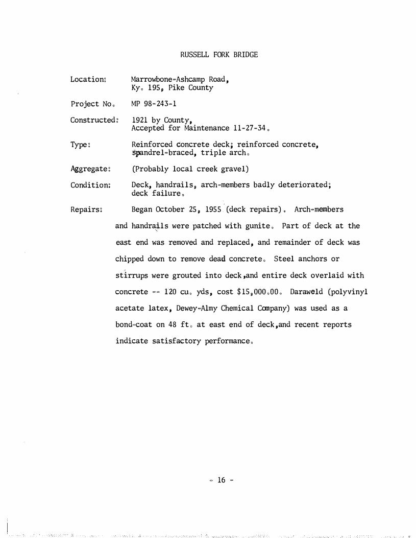
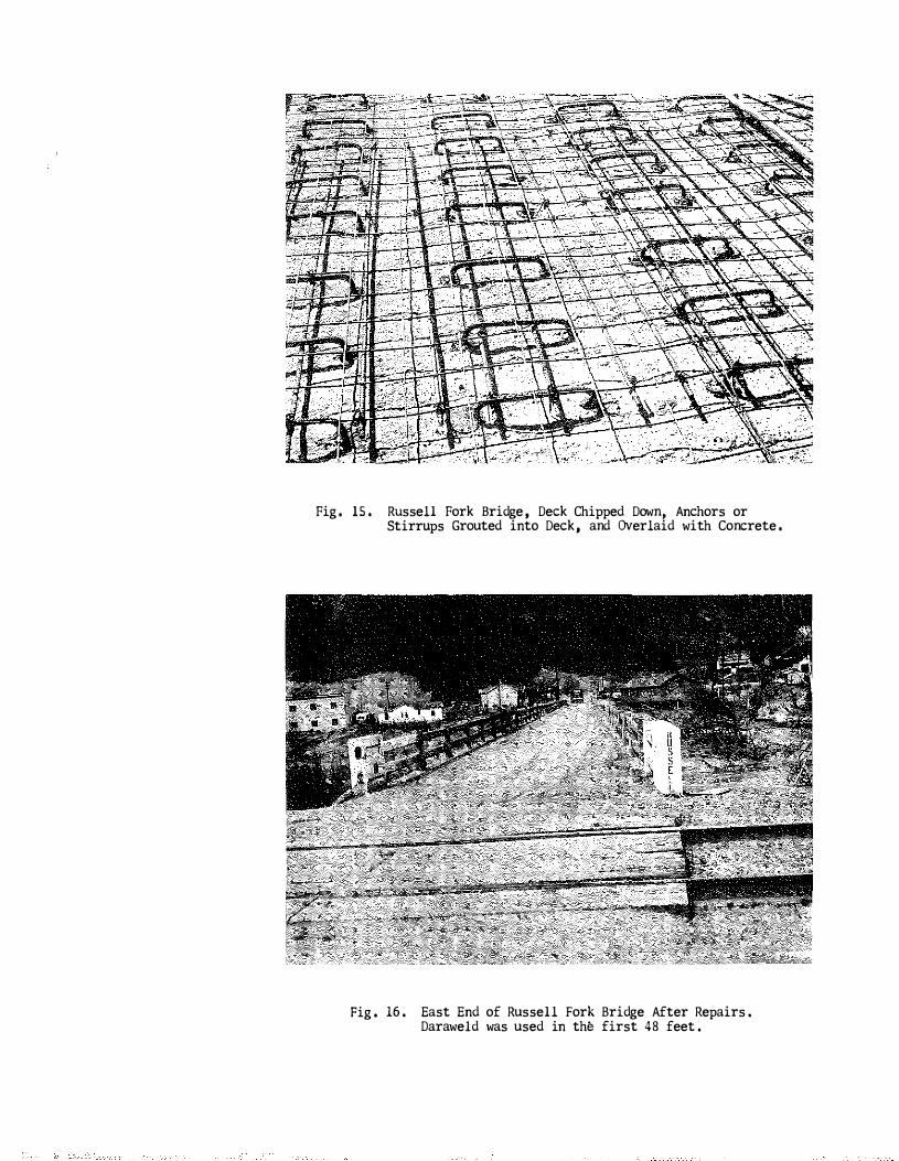
Repairs: Began October 25, 1955 (deck repairs) " Arch�mernbers
and handra�ls were patched with gunite o Part of deck at the
east end was removed and replaced , and remainder of deck was
chipped down to remove dead concrete" Steel anchors or
stirrups were grouted into deck ,and entire deck overlaid with
concrete -- 120 CU o yds , cost $1S,OOOoDDo Daraweld (polyvinyl
acetate latex , Dewey-Almy Chemical Company) was used as a
bond-coat on 48 fto at east end of deck ,and recent reports
indicate satisfactory performance"
- 16 -

Fig. 13. Russell Fork Bridge, Marrowbone-Ashcamp Road, Pike County, Ky. 195.
� � ...
c
Fig. 14. Section of Deck Removed, Replaced with New Concrete, Russell Fork Bridge.
Fig, 15, Russell Fork Bridge, Deck Chipped Down, Anchors or Stirrups Grouted into Deck, and Overlaid with Concrete,
Fig, 16. East End of Russell Fork Bridge After Repairs. Daraweld was used in the first 48 feet.

RAILROAD OVERPASS, BEUCHEL
Location: US 3l·E, Bardstown Road Jefferson County
Proj1ect No,: F 18 (6)
Constructed: Concrete poured November 11, 1955; cracks occurred in first 24 hours,
Condition: Shrinkage cracks in deck slab section 3L; between piers 1 and lA,-
Repairs: September 27, 1956; Daraweld·Mortar (1 bag, cement, 2 gaL
Reference�
water, 3,5 gal, Daraweld), Material was mixed at central
batch plant, hauled to job in ready·mix truck, dumped, and
scrubbed onto t�e deck with stiff brooms, 3/16 in, treatment,
liquid curing compound, closed to traffic 2·1/2 days, Cracks
reappeared in less than one year,
Memo, to W , S, Todd, Division of Construction, from D, H,
Sawyer, July 9, 1956, and November 5, 1956 (Research Lab, Files
P, 3,3, & C , 2,8,) ,
. 17 .
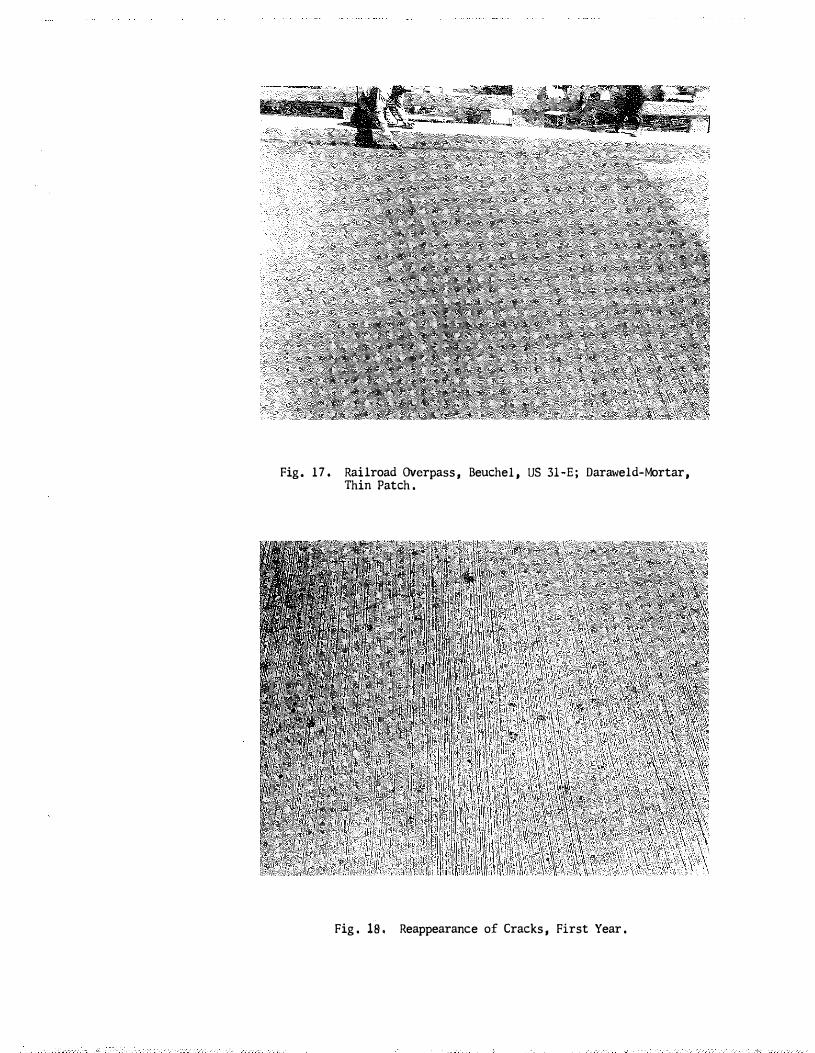
Fig. 17. Railroad Overpass, Beuchel, US 31-E; Daraweld-Mortar, Thin Patch.
Fig. 18, Reappearance of Cracks, First Year.

CLARK MEMORIAL BRIDGE
Location: Louisville, Ohio River
Project No,: MP 56� 8118�7
Constructed: 1928"29, Accepted for Maintenance November, 1946, Accepted from City 6�16�47,
Aggregate: Ohio River Gravel
Condition: Scaling, spalling, and deep deterioration; numerous bituminous patches, requiring continual maintenance during winter months, and numerous cracks in deck showing salt deposits on bottom sides,
Repairs: Bituminous patches and dead concrete removed, and deep
References:
patching was done with portland cement concrete (by maintenance
crew), Shallow patching (sand"aspha1t) was included in surfac"
ing contract, The surface was primed with a cut�back PAC�3,
and 0,4 in, sand�asphalt was placed with a paver on October 22
to 30, 195& .. (25,000 sq, yds, $13,325,00), During the second
winter, extensive spalling developed, and in March and April,
1960, extensive patching (with sand"asphalt) was required,
On October 6, 1961, wet�bottom boiler slag seal�coat (Black·
Beauty, RS�2) was applied, In October, 1962, a Kentucky Rock
Asphalt (from reserve supply) spinner seal treatment was applied
to sections of the approaches,
L "Bridge Resurfacing with Silica Sand�Asphalt Mixture,"
A Memorandum Report by L, H, Strunk, Dec, 1958, R��L. Vol, XIII,
1958, pp, 334"367,
2, "The Design of Thin, Silica Sand"Asphalt Wearing Sur"
faces for Highways and Bridges>"" by Robert L, Florence, July,
1959, RHMRL, Vol, XIV, 1959, pp, 253"310,
" 18 "

CLARK MEMORIAL BRIDGE (Cont'd,)
References: 3 , "Performance Report on Bridge Resurfacing with Silica
Sand-Asphalt Mixture," by Robert L, Florence, March, 1961.
RHMRL, Vol, XVI, Part I, pp, 175�202,
4, "Seal Coat Application to Clark Memorial Bridge," by
Robert C, Deen, January, 1962, RHMRL, Vol, XVIII, Part III,
pp, 175-188,
5, "Bridge Deck Repair Techniques on the New Jersey
Rurnpike"; Orrin Riley, Project Engineer, Howard, Needles,
Tammen & Bergendoff; presented 42nd Annual Meeting of the
Highway Research Board, January, 1963,
Inter>esting case-history of Passaic River Bridge, con
structed about 1951; over a mile long, six 1anes wide; spalling
began in 1957; ZOO to 1200 sq, ft, of spalling occurred each
month; several slabs have failed, and the lanes have been closed
while the slabs were being replaced; about 20% of the slabs had
been replaced ($360, per cu, yd,, including removal of Old cort•
crete), the top 2 in, of the new concrete was Embeco; patchirlg
consisted of Embeco, non�shrink mortar, feathered patches failed
5 to 10 times more readily than sawed�edge patchwork; dead con
crete was removed; Embeco patching or epoxy�coal tar (Guardkote
140) patches are used on the bridge as well as throughout the
turnpike; choice is dependent upon closing the area to traffic;
earlier work cost $�0, to $25, per sq, ft,, later costs were £rom
$8,50 to $8,90 per sq, ft,; part of bridge has been sealed with
Guardkote 140 and emery grit,
� 19 -

Fig. 19. Clark Memorial Bridge, North Ramp, Showing Bituminous Patches, August , 1958.
Fig. 20. Clark Memorial Bridge, South Ramp, After Bituminous Patches Removed, October, 1958.

-
Fig. 21. Clark Memorial Bridge, North Ramp, November, 1959, Sand-Asphalt Surface.
Fig, 22. Clark Memorial Bridge, South Ramp, November, 1959. Ripples in foreground are caused by deep sand-asphalt patches; one year after surfacing with sand-asphalt.
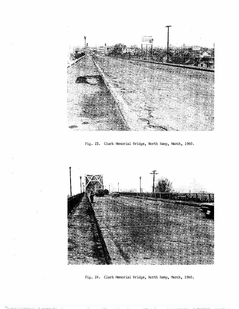
Fig, 23, Clark Memorial Bridge, North Ramp, March, 1960,
Fig, 24. Clark Memorial Bridge, North Ramp, �1arch, 1960.

Fig, 25, Clark Memorial Bridge, Removing Dead Material Preparatory to Patching, March, 1960.
Fig. 26.
Clark Memorial Bridge, March, 1960, Spalls Cleaned and Primed (SS-1) Preparatory to Patching. Patching Material was also a sand-asphalt mix. Note exposed reinforcing steel,
f"' q I
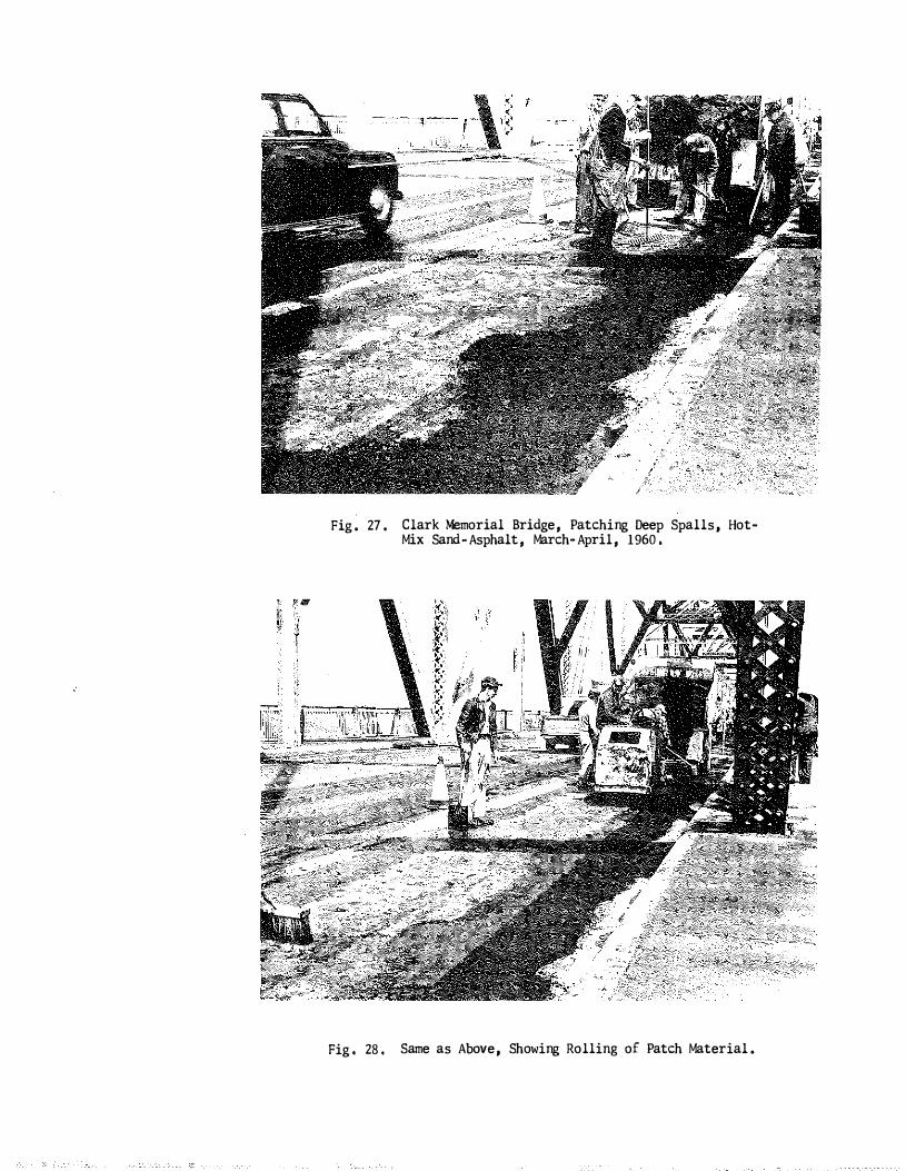
Fig. 27.
Fig, 28,
Clark Memorial Bridge, Patching Deep Spalls, HotMix Sand-Asphalt, March-April, 1960,
Same as Above, Showing Rolling of Patch Material.
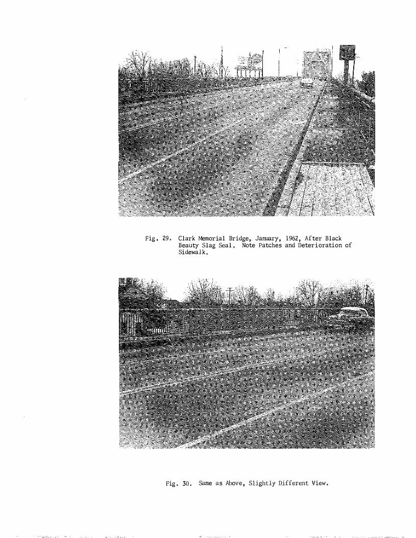
Fig, 29. Clark Memorial Bridge, January, 1962, After Black Beauty Slag Seal, Note Patches and Deterioration of Sidewalk.
Fig. 30. Same as Above, Slightly Different View,
ASHLAND�COAL GROVE BRIDGE
Location: Ohio River
Project No , : MP 10�6025�1
Constructed: 1931
Type: Three-truss, reinforced concrete deck with Kentucky Rock Asphalt surface (original surface) ,
Condition: The original Rock Asphalt surface had been overlaid
with Class I bituminous concrete (slag aggregate , 1951),
A few areas had subsenuently been patched, and pre
sumably additional resurfacing was needed because the
existing surface was slick ,
Repair� (Treatment) : Sand-asphalt surface , 0,4 in, , " and similar to
that used on Clark Memorial Bridge, was placed September
14, 1958, Performance of the sand�surface has been
References :
general ly good , Tire chains marked the surface during
the first winter ,and there is some localized surface
failure where distress was apparent in the existing surface,
Some maintenance patching has been required,
See Nos , 1, 2 and 3 listed for Clark Memorial Bridge,
� 20 -
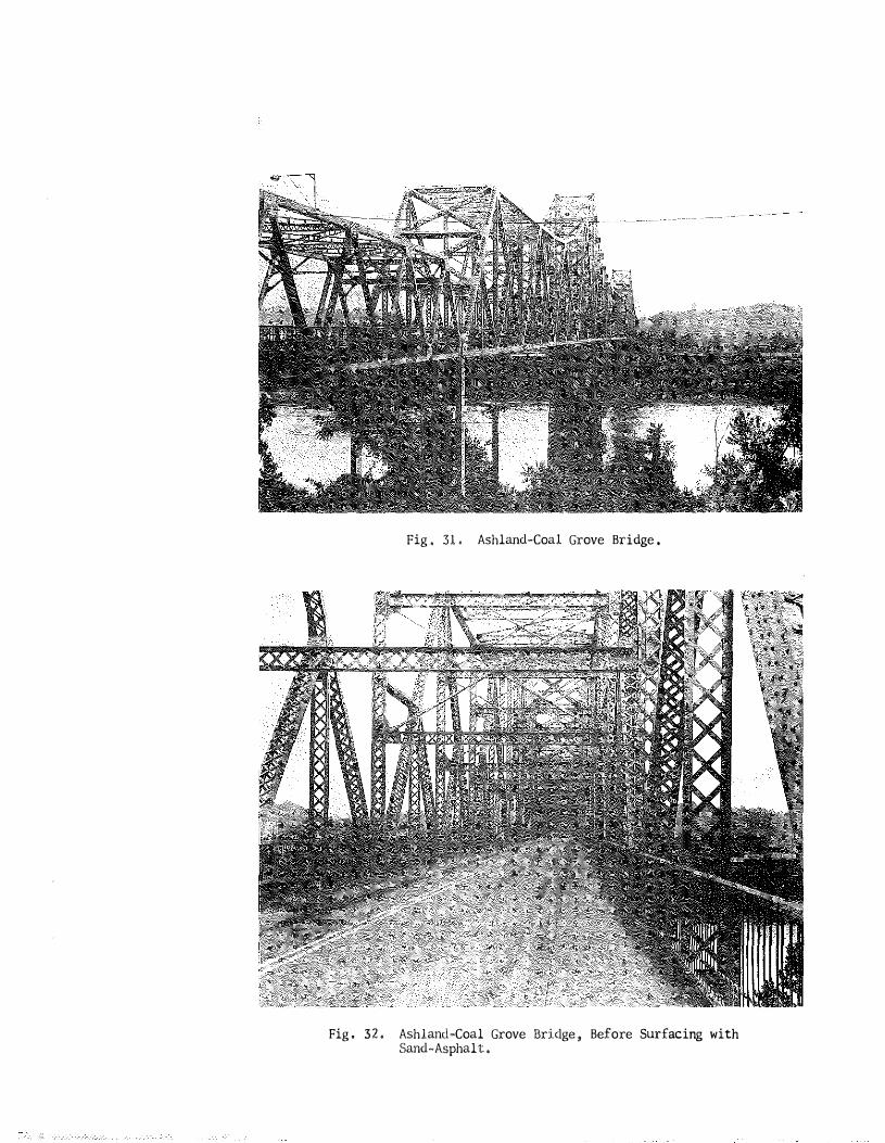
Fig. 31. Ashland-Coal Grove Bridge.
Fig. 32, Ashland-Coal Grove Bridge, Before Surfacing with Sand-Asphalt.

Fig. 33. Ashland-Coal Grove Bridge, February, 1960. Note snow and cinders in gutter and chain marks.
Fig. 34. Ashland-Coal Grove Bridge, March 1960. Note Cinders in gutter and distressed area in outer wheel track.

ST , CATHERINE ' S STREET BRIDGE
L6cation: North�South Expressway Louisville
Project j.Jo ,: MP 56-8798�HG 15 1�65-6 (7) 133 56�8798-llBl
Constructed: Completed 1�6-60
Condition: No significant distress, Bridge was arbitrarily �elected for experimental treatment,
Treatment : May 19 , 1960 , Northernmost 3/4ths of southbound lanes
treated (deck, safety walk , and half way across median) with
George W, Whiteside's 56-E-2, poly-styrene penetrant , applied
through low�pressure garden spray,
Southernmost l/4th of southbound lanes treated with a
brook-squeegee appl ication of George W, Whiteside's J�l51�40,
two-component epoxy�polysulfide , The "40" refers to the per-
centage of non-volatiles (by volume, not shown in photos) ,
Note: Polysulfide rubber (Prestite) , two-component, joint
sealer was installed in expansion joint, north end of
northbound lanes in May, 1962,
- 2 1 -
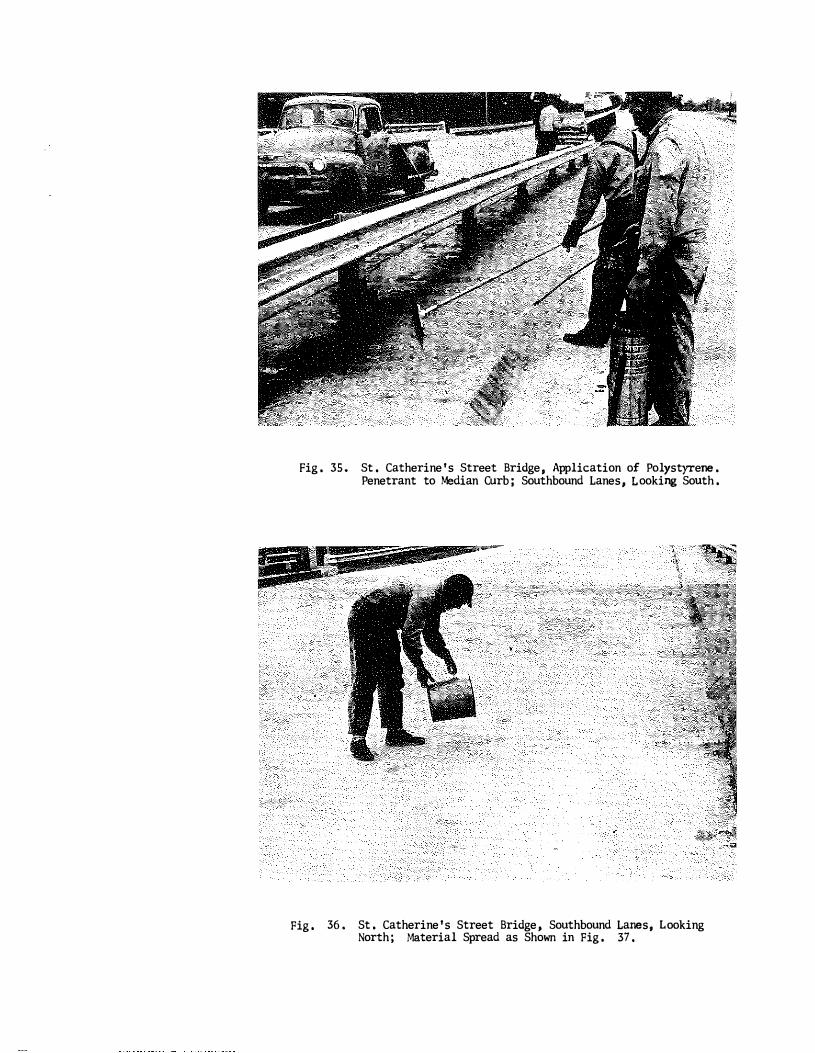
Fig. 35. St. Catherine's Street Bridge, Application of Polystyrene.
Fig.
Penetrant to Median Curb; Southbound Lanes, Looking South.
36. St. Catherine's Street Bridge, Southbound Lanes, Looking North; Material Spread as Shown in Fig. 37.

Fig. 37. St, Catherine's Street Bridge; Spreading Styrene Penetrant.
Fig. 38. St. Catherine's Street Bridge, Southbound Lanes, Looking North; Polystyrene Coating in Background.

SALT RIVER BRIDGE (TWIN)
Location: Kentucky Turnpike
Constructed: 1955
Condition:
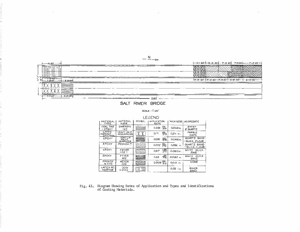
Treatment:
Severe scaling on plinths and curbs ; minor scaling on deck; numerous shrinkage and transverse cracks in deck (See Figs , 39-42),
June-October, 1960; various coating materials applied
experimentally, Technical supervision provided by contributors
of materials , Figure 43 shows the locations and identifications
of the various materials , The methods , procedures , and other
detail s are shown in sequences of pictures , Except where it i s
noted otherwise, the surface of the deck was prepared by sand
blasting , Cleaning of the deck and routing of cracks was per-
formed by Department maintenance crews , Except for the first
section at the north end of the southbound bridge , all coatings
contained sand or grit , All coatings gave light colored surfaces
except the American Bitumals Company's Heavy Duty Resurfacer
and, of course , the section where emery grit was applied to
coal tar-epoxy , The Penntrowel section appears a light gray,
but the Porter Paint section is slightly darker ,
- 22 -

Fig. 39, Twin Bridge, Salt River, Kentucky Turnpike (Looking North).
Fig, 40. Salt River Bridge, Kentucky Turnpike; Scaling Along Curb and Plinth, Cracking in Deck.
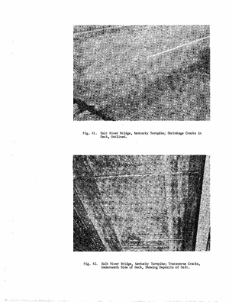
Fig. 41, Salt River Bridge, Kentucky Turnpike; Shrinkage Cracks in Deck, Outlined.
Fige 42. Salt River Bridge, Kentucky Turnpike; Transverse Cracks, Underneath Side of Deck, Showing Deposits of Salt.
N
sad �
SALT RIVER BRIDGE SCALE -(=zo'
LEGEND
Fig. 43. Diagram Showing Dates of Application and Types and Ident ifications of Coating �mterials.

Fig. 44. Salt River Bridge, Kentucky Turnpike; Application of EpoxideAlkyd, Meyer 403; Qllickspray; No Sand or Grit Applied; North End of Southbound Bridge, Looking South, (6·10·60).
rig. 45. Salt River Bridge, Kentucky Turnpike; Appl ication of EpoxideAlkyd, �'!eyer 403; North End , Southbound Bridge, Looking North, (7-13-60).

I
rig. 46, Salt River Bridges, Kentucky Turnpike; Caulking Cracks , Epoxy Mastic Caulking , 0Ieyer 401 (rilled Epoxy), (7·13·60).
Fig. 4 7, Salt Rive� B ridges , Kentucky Turnpike; Qui ckspray Guns (7·13-60).
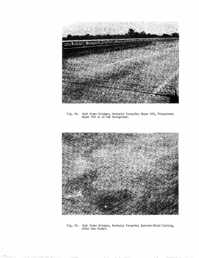
Fig. 48. Salt River Bridges, Kentucky Turnpike; Meyer 403, Foreground; Meyer 402 is in the Background.
Fig. 49. Salt River B ridges, Kentucky Turnpike; Epoxid e-Al kyd C oating, after One Winter.

Pig. 50.
Fig. 51.
Salt River Bridges, Kentucky Turnpike; Quickspray �!ixer Used to Blend Batches of Epoxy Components and Sand, (6-10-60).
Salt River Bridges, Kentucky Turnpike; Meyer 402, Epoxy Sand �brtar (Amine-Cured Epoxy; Ottawa9 Flint Shot Sand), (6-10-60).

Fig. 52. Salt River llridge, Kentucky Turnpike; Applying Meyer 402, Epoxy Sand rfortar, 6-10-60; also Applied 7-13-60 and 7-14-60 in Right-hand Lane; Meyer 402-1 Applied 8-31-60 and 9-2�60; 402Nl Contained Somewhat Greater Portion of Sand,
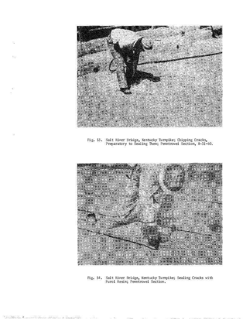
Fig. 53. Salt River Bridge, Kentucky Turnpike; Chipping Cracks, Preparatory to Sealing lhem; Penntrowel Section, 8�31�60.
Fig. 54. Salt River Bridge, Kentucky Turnpike; Sealing Cracks with Furol Resin; Penntrowel Section.
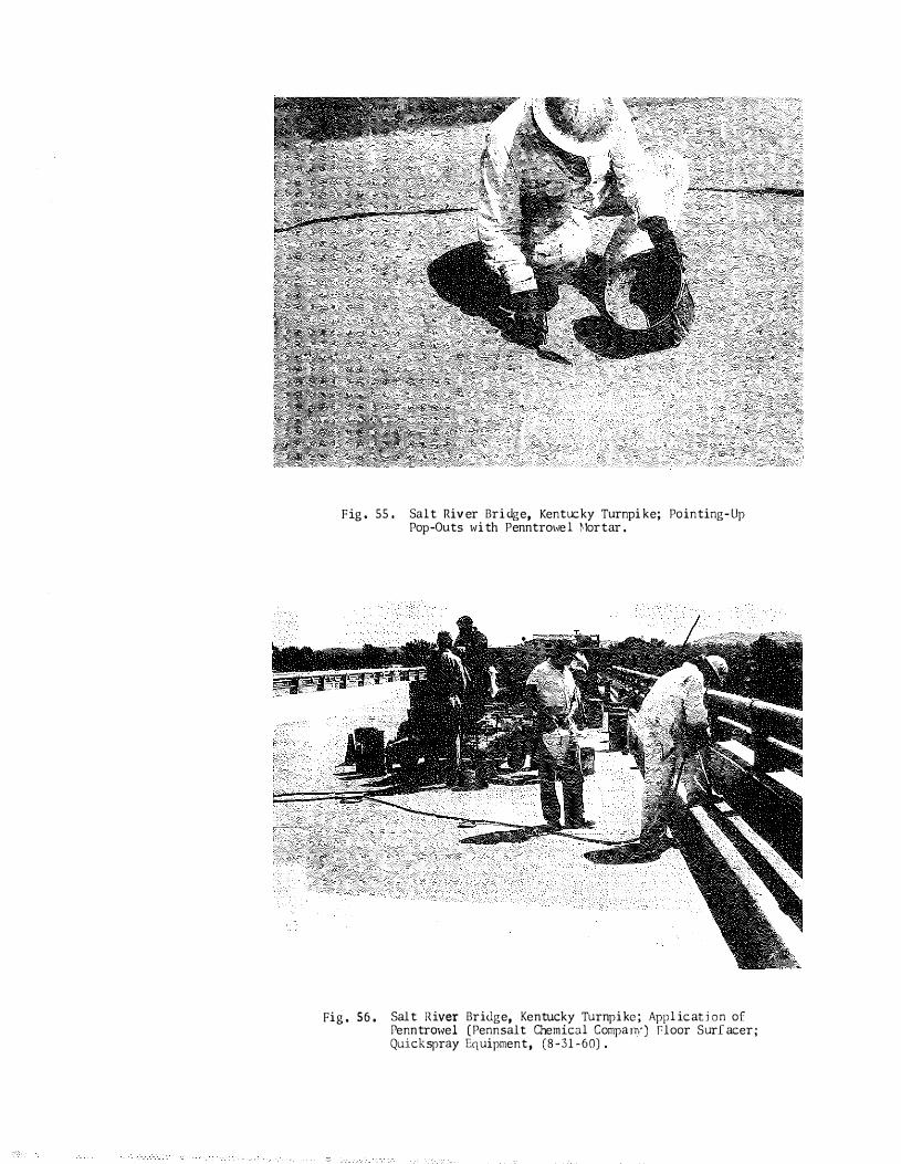
Fig . 55. Salt River Bridge, Kentucky Turnpike; Pointing-Up Pop-Outs with Penntrmvel �1ortar.
Fig . 56. Salt River Bridge, Kentucky Tu rnpike; Applicabon of PenntrO\-,�el (Pennsalt Chemical Company) Ploor Surfacer; Quickspray Equipment, (8-31-60).
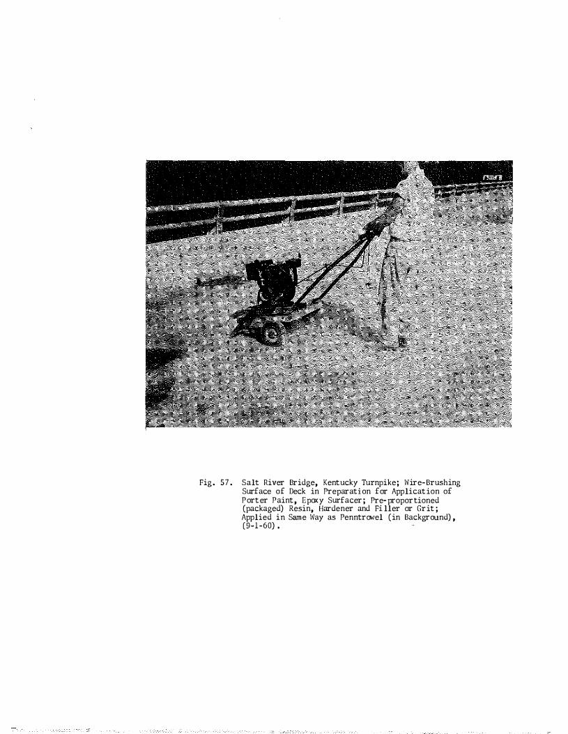
Fig. 57. Salt River Bridge, Kentucky Turnpike; Wire-Brushing Surface of Deck in Preparation for Application of Porter Paint, Epoxy Surfacer; Pre�proportioned (packaged) Resin, Hardener and Filler or Grit; Applied in Same Way as Penntrowel (in Background), (9-1-60).

Fig. 58. Salt River Bridges, Kentucky Turnpike; D eep-Routing Transverse C racks, Preparatory to Placing Latex-�1ortar Overlay, October9 1960.
Fig. 59. Sal t River Bridge� Kentucky Turnpike; Placing Latex (Dow 2144) -'lortar Overlay; Approximately 1/4 inch, October, 1960.
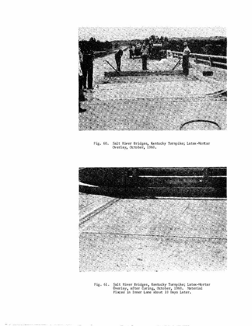
Fig. 60. Salt River Bridges, Kentucky Turnpike; Latex-�1ortar OVerlay, October, 1960.
Fig . 61. Salt River Bridges , Kentucky Turnpike; Latex�Mortar Overlay, after Curing, October, 1960. �taterial Placed in Inner Lane about 10 Days Later.

Fig . 62. Salt River Br1dge9 Northbound9 Kentucky Turnpike; Scrubbing Deck with Water and Tri-Sodium Phosphate, Preparatory to Applying American Bitumuls ; Heavy Duty Resurfacer, July 7, 1960.
Pig. 63. Salt River Bridge, Kentucky Turnpike; Rinsing after Scrubbing; Preparatory to Application of American Bi twnul s � lleavy Duty Resurfacer � July 7, 1960,
• �
�
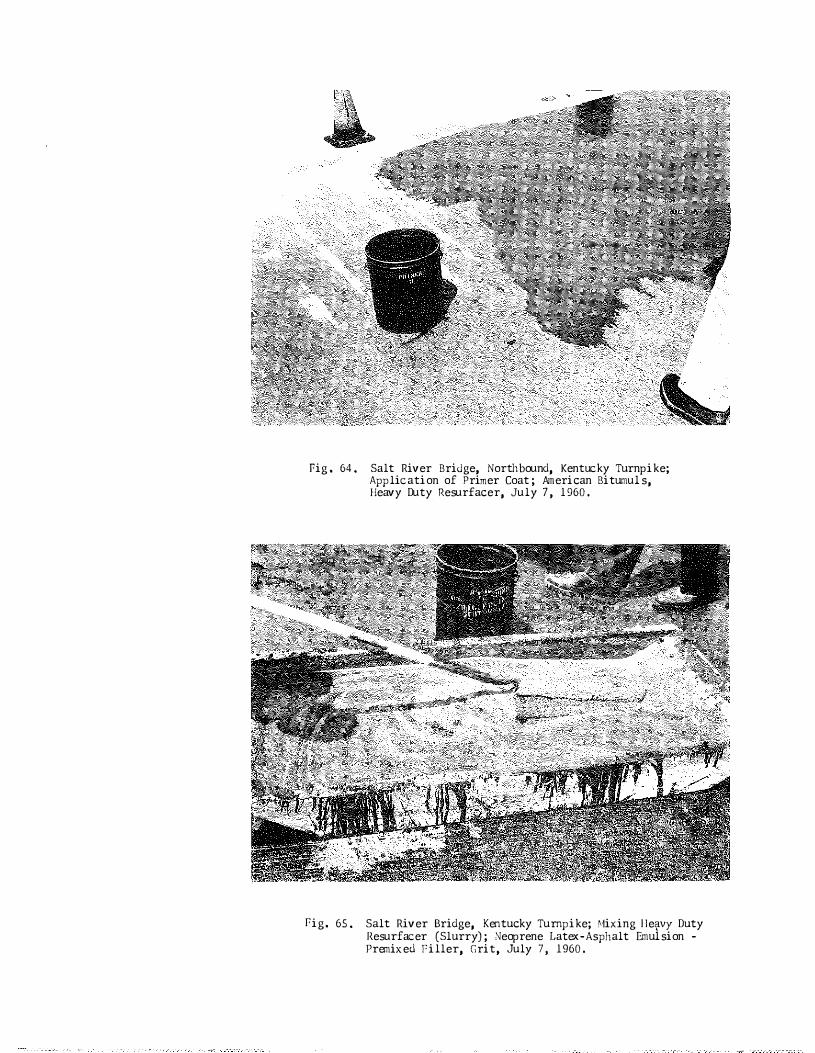
Pig . 64. Salt River BriJge, Northbound, Kentucky Turnpike; Application of Primer Coat ; American Bitumuls, Heavy Duty Resurfacer, July 7, 1960.
Pig. 65. Salt River Bridge, Kentucky Turnpike; Hixing lleo(.VY Duty Resurfacer (Slurry); 0Jeoprene Latex-Asphalt Emulsion -Premixed Filler, Grit, July 7, 1960.

Fig . 66. Salt River Bridge, Kentucky Turnpike; Spreading i\rnerican Bitumuls Heavy Duty Resurfacer, July 7, 1960.
'
Fig, 67, Salt River Bridge, Northbound , Looking South; Heavy Duty Duty Resurface; Left Lane opened to Traffic; July 8, 1960.

Fig. 68. Salt River Bridge, Kentucy Turnpike; American Bitumuls Heavy Duty Resurfacer; Severe Shrinkage Cracks; Ten Days to Two 1\'eeks Afterwanls.
Fig. 69. Salt River Bridge, Kentucky Turnpike; �erican Bitumuls Heavy Duty Resurfacer; Sho\1/ing Peeling During First Winter,
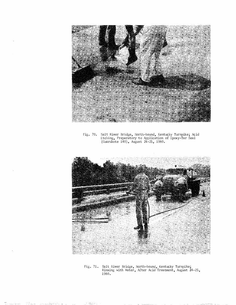
Fig. 70. Salt River Bridge, North-bound, Kentucky Turnpike; Acid Etching, Preparatory to Application of Epoxy-Tar Seal (Guardkote 140), August 24-25, 1960.
Fig. 71. Salt River Bridge, North-bound, Kentucky Turnpike; Rinsing with \'Yater, After Acid Treatment, August 24-25, 1960.
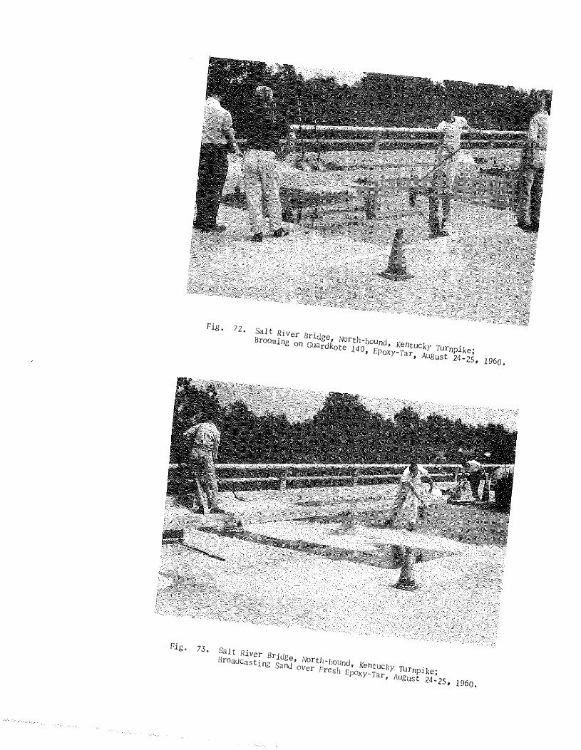
Fig.
Fig. 72, Salt River Bridge, North-bound, Kentucky Turnpike; Brooming on Guardkote 140, Epoxy-Tar, August 24-25, 1960,
73, SaJt Hiver Bridge, North-bound, Kentucky Turnpike; Broadcasting Sand over Fresh Epoxy-Tar, August 24-25, 1960,
1 �
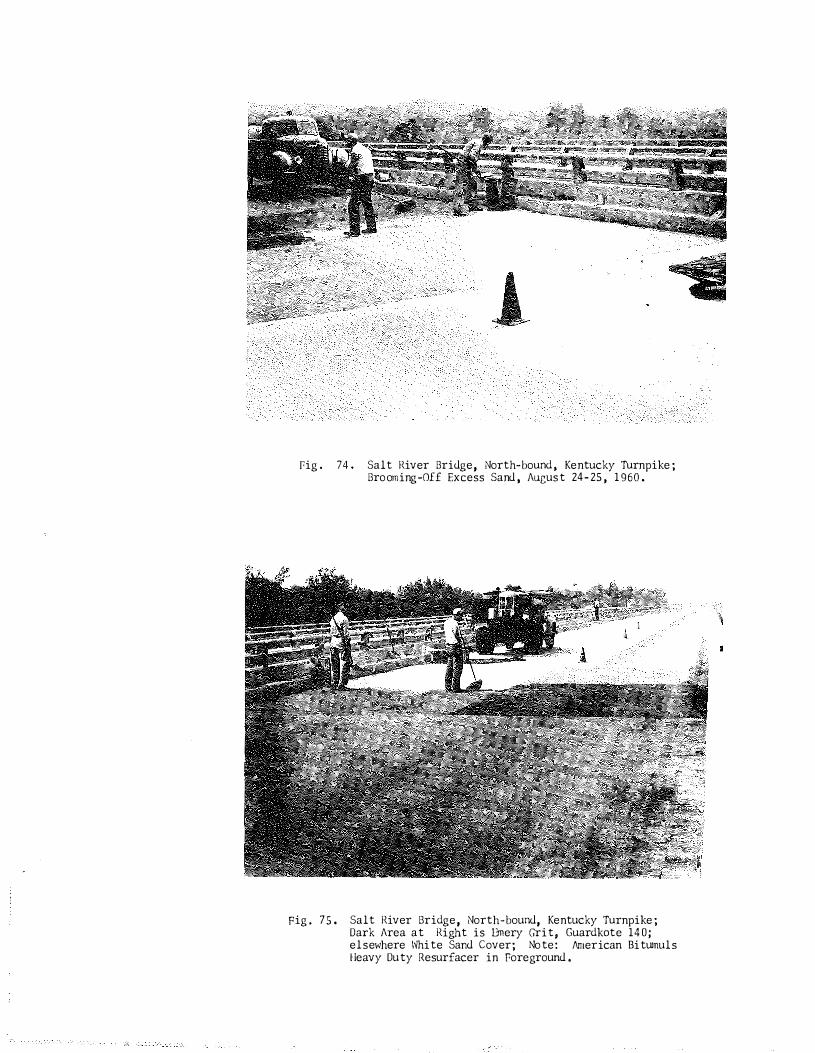
Pig. 74. Salt River Bridge, North-bound, Kentucky Turnpike; Brooming-0££ Excess Sand, August 24-25, 1960.
Fig. 75. Salt River Bridge, North-bound, Kentucky Turnpike; Dark Area at Right is 13mery Grit, Guard kate 140; el sewhere White Sand Cover; Note: llmerican Bitumul s Heavy Duty Resurfacer in foreground.
\.· '

Location:
PRICE PIKE BRIDGES (TWIN)
I -75, South of Mile Post 179 , Covington-Lexington Road, Boone County
Project No,: MP 8 -550-HG4
Completed:
Condition:
Repairs:
10-26-60 (date of acceptance)
Rain damaged fresh,uncovered concrete during construction;
center span, northbound lanes .
Summer, 1960; Sika Bonding Compound (epoxy-polysulfide)
and 1/4-inch mortar topping ; feathered edges ; used to build up
a smooth surface; bonded overlay covered about 75% of center slab,
Note: Scaling has been reported in the south span of the south· bound lanes •
- 23 -
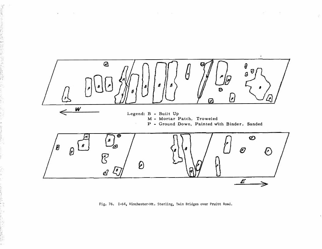
TWIN BRIDGES OVER PRUITT ROAD
Location:
Constructed:
I -64, Winchester-Mt, Sterling,
1960
Condition: Deck was uneven, Contr,ctor was required to smooth by
grinding and to build up low places with epoxy mortar,
Repairs: June-July, 1960 ; Geo, W , Whiteside ' s 59-D-3 (polysulfide-
Reference:
epoxy) binder and sand used to build up surface of deck to
template grade, A diagram, Fig , 76, shows the location and
types of build-up attempted arid more complete descriptions are
given below:
B - Build-up consisting of mop- coat of binder sprinkled
with sand and broomed , This procedure was repeated
until the desired template grade was reached ,
M - Binder and sand . mortar-mix, was troweled into de
pressions and feather�ed,
P - High places were ground down, painted with binder,
and sprinkled with sand,
Figures 77 through 82 show the condition of the overlays as of
the indicated dates.
"Those Wonderful Epoxies: What They Will and Won ' t Do,"
Feature Article, Engineering News-Record, July 12, 1962 , A
general treatise on epoxies,
- 24 -
9 - I A r--1r'l g QB
GQG (J
0 (!) < w
Legend: B - Built Up M - Mortar Patch, Troweled
P - Ground Down, Painted with B inde r , Sanded
8a>0
fJ ta tr il � 0
(Z)
flJ 0
E --..;;;..-
Fig. 76. I-64, l'Jinchester-Mt . Sterling, Twin Bridges over Pruitt Road .

LAKE CUMBERLAND BRIDGE
Location:
Project No o :
Kyo 901 Burnside-Monticello Road
MP 100- 155-3
Constructed: Completed 8�21 � 5 1 , Accepted 1 1�10�51
Deck-Truss, Reinforced Concrete Deck, 8 Inches o Type :
Condition: Deep deterioration in some slabs ; seemed to be related
to pouring patterno Slabs 28�ft o in length were poured al�
ternatelyo Adjoining slabs were markedly different in qualityo
Figures 83 through 86 i l lustrate typical conditiono
Repairs: Summers of 1961 and 1962 (began July 24 , 196l) o The deck was
originally intended to be scarified uniformly to a depth of
l/2 inch o Unsound concrete was removed by chipping and rout�
ing o Cutting to the ful l 1/Z�inch depth proved to be too ex�
hausting, and in order to decrease the amount of cutting to be
done, the depth of the cut was reduced to 1/4 inch for most of
the deck and to 1/8 inch for the remainder o I t was necessary
to cut the ful l 1/2 inch where approaching the finger dams
and the ends of the bridge in order to allow 1/2 inch for the
planned minimum thickness of overlay material o Of course, it
was stil l necessary to cut considerably deeper in the places
where the worst deterioration had occurred o
The cleaning was the most time consuming and expensive
phase of the work o This included the use of: two Tennant routers
to remove the undesirable surface of a concrete slab to a depth
of from 1/4 inch to 1/ 2 inch in a 4�1/2 inch wide pas s ; one
Triplex tamper equipped with three j ackhammer drill bits ;
� 25 �

� 26 �
conventional j ackhammers for edging next to the curbs where
a router could not reach; a sandblaster to remove paint and
latex�cement slurry from the curbs and dirt and laitance from
the sidewalks ; stiff bristle street brooms and compressed
air to remove dust and other debris , A concrete saw was also
employed to cut expansion joints for fil ling with sealer ,
The overlay material consisted of 1/2 inch of portland
cement mortar containing experimental admixtures : Dow Latex
560 (saran, vinylidene chloride) and Dow Latex 2144 (a styrene
butadiene) (See Figs , 58 thru 6 1 , Salt River Bridge, Kentucky
Turnpike, October, 1960) , These admixtures were acclaimed
to improve the toughness of mortar and to greatly improve the
bond strength between mortar toppings and old concrete , The
Dow Company had agreed to furnish the latexes and sufficient
epoxy resins to provide an epoxy�sand seal over the major
portion of the mortar topping and to provide technical services
during their application , The materials and preparations are
listed in tabulations which follow, There also follows an
accounting of estimated costs of the work , Figure 87 is a dia�
gram which shows the location of the subject materials on the
deck ,
The appearance of the finished deck seems to be quite
satisfactory , It is a tan color , The only seriously objec�
tionabl e feature of the surface is the roughness in the east�
bound lanes which was caused partially by attempts to strengthen
� 27 -
the epoxy- sand seal at the joints (See Fig , 99), Although
templates were placed for the screed to travel on while placing
the mortar topping , the mortar set very quickly and it was
very difficult to smooth out any ridges that might have been
left by manipulations of the screed , Curing was also rather
critical - � drying shrinkage (cracks) developed unless the
curing blanket was applied almost immediately fol lowing the
screeding , Some of the flaws which contribute to the roughness
are attributed to inadequacies in method of screeding and finishing ,
Note: Comparative roughness ratings were obtained on
the WB lane before ,any repair work was started and \<I on the EB lane after completing the repair work (See
Fig , 99) , The WB lane rated 536 as compared to 8 1 1
for the E B lane (the higher rating indicates a higher
degree of roughness ; for further comparison of these
ratings with respect to pavements in general , see :
"Pavement Roughness Studies , " by R, L , Rizenbergs,
Rl-JMRL , Vol , XVI I, Part .I , 1962, pp , 292 ,)
Descriptive photographs of the operations are given in Figs ,
87 thru 100,
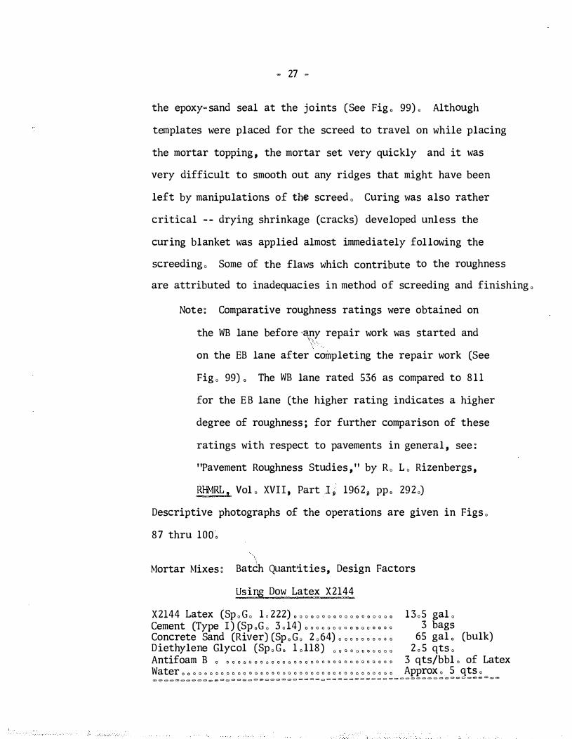
Mortar Mixes: Bat2h Quant•ities, Design Factors
Using Dow Latex X2144
X2144 Latex (Sp , G , 1 , 222) , , , , , o , , o , , , o , , , , , 13 o5 gal , Cement (Type I ) (Sp ,G , 3 o 14) , , 0 o o , , o o , , 3 bags Concrete Sand (River) (Sp , G , 2 ,64) o o o o o o o ' ' ' 65 gal , (bulk) Diethylene Glycol (Sp , G , L ll8) " " " " ' " 2 o 5 qts , Antifoam B o o o o " o o o 0 o o o " o o o o o a o o o a 0 o o o o o ., o 3 qts/bbl o of Latex Water o a o o c o o o o o a o " o a o o o a o o o o o o o o o a o o a o o a a o o Approx o 5 qts o = = = = = = = = = = = = = = = = = = = = � = = = = = = = = = = = = = = = = = = = = = = = = = = = = = � = = = = = = = = = = =
- 28 -
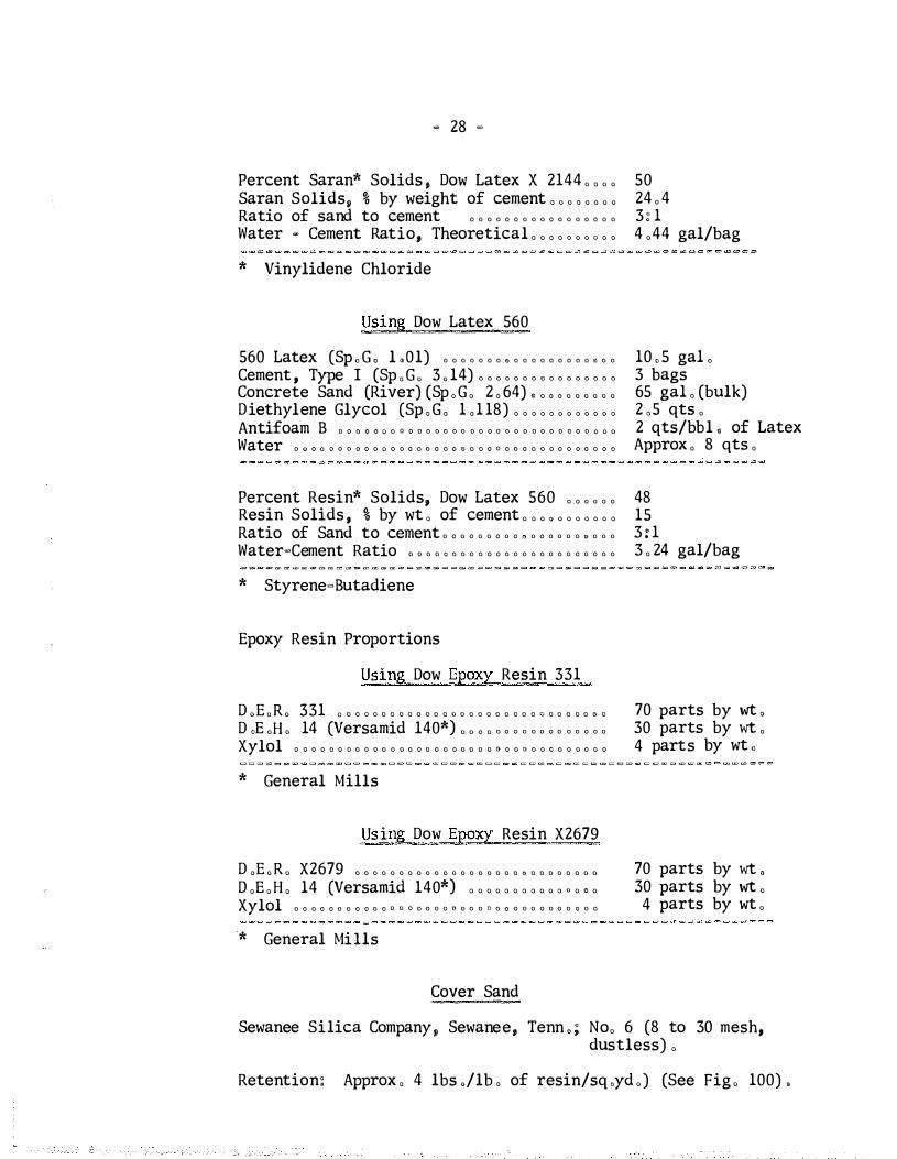
Percent Saran* Solids , Dow Latex X 2144 , , , , Saran Solids, % by weight of cement , , , , , , , , Ratio of sand to cement a o o o a a o o o a o a o o a a o
Water - Cement Ratio, Theoretical , , , , , , , , , ,
* Vinylidene Chloride
Using Dow Latex 560
560 LateX (Sp o G o l oOl) o o o o o o o o o o o o o o o o a o o o
Cement , Type I (Sp , G , 3 , 14) o o o o o o o o o o o o o o o o
Concrete Sand (River) (Sp , G , 2 , 64) , , , , , , , , , , Diethylene Glycol (Sp , G , 1 ,1 18) , , , , , , , , , , , , Antifoam B a a o a a " a a a a a o o o o a a a a o a a a a o a a a a a a o
Water a " a a " a a a a a " a a a a o a o a , a a a a a o a a a a a a a a o a "
Percent Resin* Solids, Dow Latex 560 , , , , , , Resin Solids , % by wt , of cement , , , , , , , , , , , Ratio of Sand to cement a a o a o o a a a a a a o a a o a a o o
Water=Cement Ratio a a o a a o o a o a a o a a o o a o a a a a o o
* Styrene-Butadiene
Epoxy Resin Proportions
Using Dow Epoxy Resin 331
D ,E ,R , 331 0 0 0 0 0 0 0 0 0 0 0 0 0 0 0 0 0 0 0 0 0 0 0 G 0 0 0 0 0 0 0
D aE aH a 14 (Versamid 140*) a a a a o a a a a a a a a a a o a
Xylol a a a a a a a a a a a a a a a a a a o a a a a () a a " o o " a a a a o a
* General Mills
Using Dow Epoxy Resin X2679
D ,E , R , X2679 o o o o o o o o o o o o o o o o o o o n o o o o o o o o
D ,E , H , 14 (Versamid 140*) , , , , , , , , , , , , , , , Xylol a a o a a a a a a o a a a a a o a a " a o a a o a a a a a a a a a a a
* General Mills
Cover Sand
50 24 , 4 3 : 1 4 ,44 gal/bag
10 , 5 gaL 3 bags 65 gal , (bulk) 2 ,5 qts , 2 qts/bbl , of Latex Approx , 8 qts ,
48 15 3 : 1 3 , 24 gal/bag
70 parts by wt , 30 parts by wt , 4 parts by wt o
70 parts by wt , 30 parts by wt ,
4 parts by wt ,
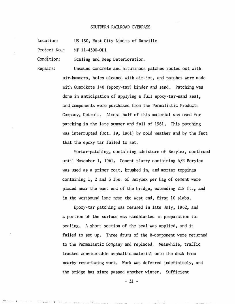
Sewanee Silica Company, Sewanee, Tenn . ; No, 6 (8 to 30 mesh, dustless) ,
Retention: Approx , 4 lbs ,/lb , of resin/sq ,yd ,) (See Fig , 100) ,
- 29 -
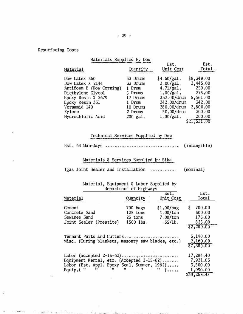
Resurfacing Costs
Materials Suppl ied by Dow
Material quantity
Dow Latex 560 Dow Latex X 2144 Antifoam B (Dow Corning) Diethylene Glycol Epoxy Resin X 2679 Epoxy Resin 331 Versamid 140 Xylene Hydrochloric Acid
33 Drums 33 Drums 1 Drum 5 Drums 1 7 Drums 1 Drum 10 Drums 2 Drums ZOO gal ,
Est , Unit Cost
$ 4 , 60/gal , 3 , 00/gaL 4 , 71/gaL LOO/gaL 333,00/drum 34 2 , 00/drum 28 0,00/drum 5 0 , 00/drum
LOO/gaL
Technical Services Supplied by Dow
Est , Total
-
$ 8 , 34 9 , 00 3 , 445 ,00
259 ,00 275 ,00
5 ,66LOO 34 2 . 00
2 , 800,00 200 ,00 200 ,00
$ zi,s�I , oo
Est o 64 Man�Days c c o o o o o o o o o o o a a o o o o o o o o o o o o o o o o (intangible)
Materials & Services Suppl ied by Sika
Igas Joint Sealer and Installation , , , , , , , , , , , (nominal)
Material , Equipment & Labor Supplied by Department of Highways
Est , Material Quantity Unit Cost
Cement Concrete Sand Sewanee Sand Joint Sealer (Prestite)
700 bags 1 25 tons 25 tons 1500 lbs ,
$ LOO/bag 4 ,00/ton 7 , 00/ton
, 55/lb '
Tennant Parts and Cutters a a o o o a o a o a o a o o a a o o o a o a a
Mise , (Curing blankets , masonry saw. blades, etc, )
Labor (accepted 2=15=62) a a a a o o 0. "' a o · O< o: <j d o a a a a a a o a a
Equipment Rental , etc , (Accepted 2-15-62) , , , , , , , Labor (EsL AppL Epoxy Seal , Summer , 196 2) , , , Equip a ( tt 1 1 n " n " ) a a a a a
Est , Total
$ 700 .oo 500 .00 175 ,00 8 25 . oo
$2, zoo ,00
5 , 140 .00 2,160.00
$7 ,3oo.oo 1 7 , 294 ,40
7 , 921 .05 3 ,500 ,00 1 , 05 0 , 00
$,3\J, z6sAs

� 30 �
Technical Supervision (Research)
Est o 75 Man=Days o o o o o o o o o o o o o o o o a a o o o o a o o o o o a (intangible)
Estimated Total Cost of Work
$ 21 ,53 1 ,00 39,265 ,45 6o,796,as
Dow, Exclusive of Intangibles , , , , , , , , , , , , , , , , Department , Exclusive of Intangibles , , , , , , , , , ,
Gra)'ld Total (Estimated) , , $
References : "Latex Modified Portland Cement Mortar Renews Bridge Deck, " Feature Article, Engineerin� News�RecordL Sept, 7 1 1961 , (This is an account of the work on t e Lake Cumberland Bridge
during 1961 , Photographs of the work and descriptions of the materials are included) ,
"Dow Latex 5 60 for Portland Cement Compositions , " Bulletin Dow Chemical Company, Coatings Technical Service, Sept , 1959 ,
"Experimental Latex X� 2144 Modified Portland Cement Mortars ," A Technical Report (F 602) , Dow Chemical Company, Coatings Technical Service ,
"Resurfacing Concrete Bridge Decks with Dow Latex 560 Modified Portland Cement Mortar," A Technical Report , Dow Chemical Company, Coatings Technical Service , Feb , 1960,
"Latex Modified Mortar in the Restoration of Bridge Struc" ture," S , M , Cardone , Chief , Maintenance and Operations , and
. M , G , Brown, Chern , Engr , , Michigan State Highway Department ; and A, A , Hill , Coatings Technical Service, Dow Chemical Company ; Bulletin No, 260, Highway Research Board, 1 960 ,
Note : Also refer to Bal l " s Fork Bridge MP 1 20�4, Russell Fork Bridge, MP 98� 243-1 , and to Railroad Overpass Beuchel ; Daraweld (polyvinyl acetate latex) modified mortar overlays ,
"Polyester Overlays for Portland Cement Concrete Surfaces , " by L , E , Santucci, California Research Board , January, 1963 ,
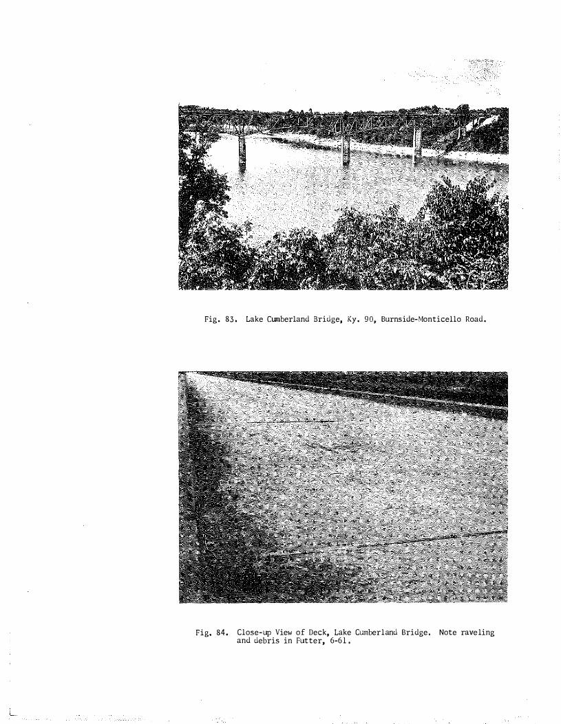
Fig. 83. Lake Cumberland Bridge, Ky. 90, Burnside-Monticello Road.
Fig, 84. Close-up View of Deck, Lake Cumberland Bridge. and debris in Futter, 6-61.
Note raveling
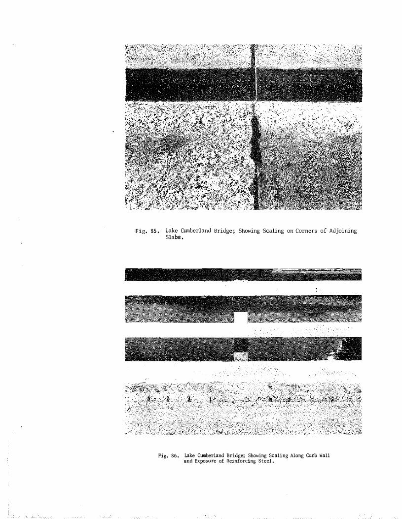
Fig. 85 . Lake Cumberland Bridge ; Showing Scaling on Corners of Adjoining Slabs .
Fig. 86 , Lake Cumberland �ridge; Showing Scaling Along Curb Wall and Exposure of Reinforcing Steel .

G) , , , IA"' "VA 3 • /h :D. du.J/.J.J f I I J_:J.a1.;1..lv.oLLizJaJ.A •. IY.ol.
® JJ W' £ D Y l?��i .2. 7 - V If A )., i)a I 0 I I I '
I I , 1 :3� L rE s�iz, (1)1..- \ ••• l"�' ],.,, Lko ••"fo- ••lv • • • � .- rJ J i 1 .oloAA LAr.<iY 15'•
.ti.s.l/ st• . .t.o., A'QrlcoYEHF. �t, f•· I"�··{"!''"'
o att 'Jf.H7"f H"Qr :co'(F/?jE 'Ell§:'" 1 1 I v�'Rii!AHiJJ 1¥0 ¥•
;z.t-lf-4- 1 _I_. I Slo
I- ; -l- � --+-s � ) iF e + 1 + ro-lf. 11 I� +13 '"'+ ,,-4 J6 + 11' +-;s+ 1'1'+"' ... r+.oo+...-+�,+�·+�--ll-,.o-1-" -1-u nH;JS+s� .<7-!,. .j...., + ... + .,, -1- P--1- �·-+ ��-�- �� +Jf6-l-'17 41 ��-�--�f-l- 5• .-..J.--s�-
0��� 6o' I 6o' hw'1
To fJYRN>IJ)E -
kr.S.f>Ec., _I B. fHil
Ji'ElsT�T 'O.LiYS�LJ::-i.z!E Ri7 S � ! IR: .TQiM;l--sjEAII;E
Fig. 87, Diagram of Lake Cumberland Bridge, Showing Locatin of Experimental Materials used in Resurfacing Deck . Although the eastbound lane (to Burnside) was cOmpleted and opened to traffic before work was started on the opposing lane, the lanes replicated each other in regard to
.
apportionment and location of materials (exceptions �e noted) . Line 1, above, shows the portions (full width) of the deck in which the two latexes were used in the mortar topping (latexmodified mortars) . Line 2, in the order of application, shows the location of joint sealers (fUll width, exce�t as noted) . Line 3 shows the scheduling (again full width) of epoxy resin seal materials, and line 4 shows their respective rates of application.
The application of latex-modified mortar began July 27, 1961, at the east end of the eastbound lane and the lane was completed September 5 , 1961; the application of epoxy resin seal began September 11 _(except for first 60 ft . , east end, trial run, August 4),and was completed September 18; opened to traffic September 24, 1961 . The application of latex-mortar in the westbound lane began at the west end October 16, 1961, and was completed October 19, 1961. Application of epoxy seal in westbound lane was deferred until June 21, 1962; completed June 28, 1962.
.zs' l {,o'
To Mo!fficHLO �

-· - ·- .
�
\..
Fig. 88. Triplex Tamper Equipped with Star�Bits; Removing Unsound Concrete, Note diaper on air compressor to catch oil drippings .
Fig. 89. Tennant Router used for Scarifying and Removing Dead Concrete,
(j\'ili
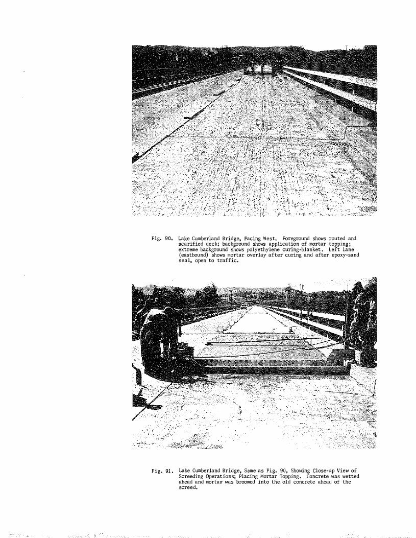
Fig. 90.
Fig. 91 .
Lake Cumberland Bridge, Facing West. Foreground shows routed and scarified deck; background shows application of mortar topping ; extreme background shows polyethylene curing-blanket . Left lane (eastbound) shows mortar overlay after curing and after epoxy-sand seal, open to traffic.
Lake Cumberland Bridge, Same as Fig. 90, Showing Close-up View of Screeding Operations; Placing Mortar Topping . Concrete was wetted ahead and mortar was broomed into the old concrete ahead of the screed,

Fig. 92. Lake Cumberland Bridge, Over�all View, Facing East, Showing JointSealing Operations in Eastbound Lane ,
-
Fig. 93. Sawing out Wood Strips which were Placed in the Mortar Overlay to Preserve the Joints in the Deck -- to be Removed and Joints Resealed,

- --- - - -- - · � - - .
Fig . 94. Filling Joints with Prestite, No. 404, Pourable Joint Sealer (TwoComponent, Polysulfide Rubber) . Note: This material was later found to be reactive (de-polymerized, re-liquified) toward asphaltic materials. About 35 joints or portions thereof were reopened the following summer, 1962; sponge rubber inserts were installed in the joints to insulate new joint sealer from the asphaltic material below. The joints were repoured with the polysulfide compound ,

Fig. 96, Lake Cumberland Bridge, Facing East, Broadcasting Sand onto Newly Applied Epoxy Resin, September, 1961. Note: Curb and sidewalk section here were sandbalsted and sealed with epoxy-sand ahead of the application to the deck � - elsewhere the two operations \�ere carried along together.
Fig. 95. Lake Cumberland Bridge� Facing West� Showing Application of Epoxy Resin to �Iortar OVerlay; Coarse Sand (from Sewanee9 Tenn .) Applied in Poreground , Pyles mixing pump and drums of epoxy components were carried ahead in pick-up truck. Septemberg 1961,

Fig. 97. Lake Cwnberland Bridge ; Eastbound Lane; Squeege-Application of Dow 331 Epoxy Resin, September, 1961.
Fig. 98 , Lake CUmberland Bridge; 1\iestbound Lane, Facing East; Application of Epoxy Resin; Pyles Gun; Workman ' s Protective Suit Ventilated through Hose from Tanks of Compressed Breathing-air Carried in Truck. Wood laths were used as spacers to help gage application rate, July-August , 1962. Note: The latex mortar i n this lane had been exposed to traffic through the winter sand blasting and other cleaning irrnnediately preceeded the application of epoxy.
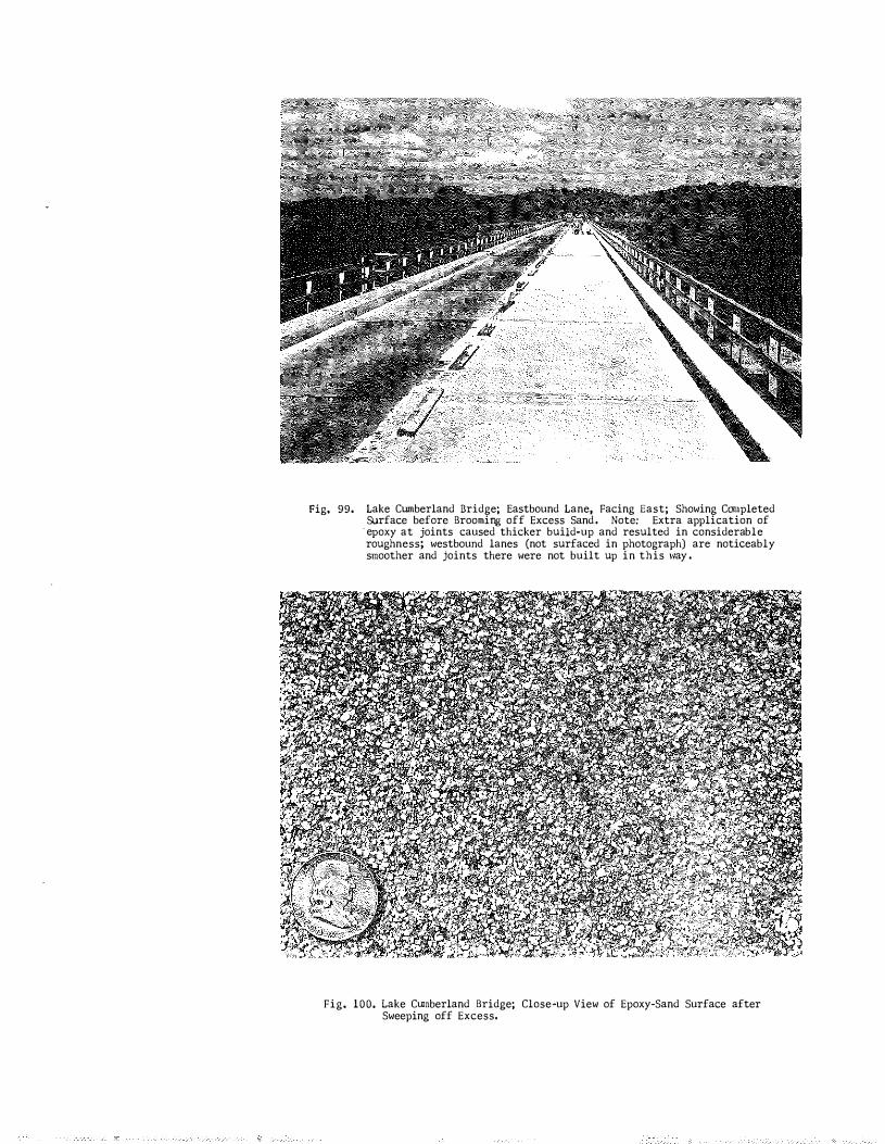
Fig, 99. Lake Ctunberland Bridge; Eastbound Lane, Facing East; Showing Completed Surface before Brooming off Excess Sand . Note: Extra application of
· epoxy at joints caused thicker build-up and resulted in considerable roughness; westbound lanes (not surfaced in photograph) are noticeably smoother and joints there were not built up in this \�ay .
Fig. 100. Lake Cwnberland Bridge; Close-up View of Epoxy-Sand Surface after Sweeping off Excess.
SOUTHERN RAILROAD OVERPASS
Location:
Project No , :
US 150, East City Limits of Danville
MP 11·4300-0Hl
Condhion:
Repairs :
Scaling and Deep Deterioration ,
Unsound concrete and bituminous patches routed out with
air-hammers , holes cleaned with air-jet , and patches were made
with Guardkote 140 (epoxy-tar) binder and sand , Patching was
done in anticipation of applying a full epoxy-tar-sand seal ,
and components were purchased from the Permalistic Products
Company, Detroit . Almost half of this material was used for
patching in the late summer and fall of 1961 , This patching
was interrupted (Oct , 19, 1961) by cold weather and by the fact
that the epoxy tar failed to set ,
Mortar-patching , containing admixture of Berylex , continued
until November 1 , 1961 , Cement slurry containing A/E Berylex
was used as a primer coat, brushed in, and mortar toppings
containing 1 , 2 and 3 1bs , of Berylex per bag of cement were
placed near the east end of the bridge, extending 215 ft , , and
in the westbound lane near the west end , first 10 slabs ,
Epoxy-tar patching was resumed in late July, 1962, and
a portion of the surface was sandblasted in preparation for
sealing , A short section of the seal was applied, and it
failed to set up , Three drums of the B-component were returned
to the Permalastic Company and replaced , Meanwhile, traffic
tracked considerable asphaltic material onto the deck from
nearby resurfacing work, Work was deferred indefinitely, and
the bridge has since passed another winter , Sufficient
• 31 •
- 32 -
materials are on hand for the completion of the seal -
provided that extensive additional patching will not be
required o
The present condition of the deck is shown in Figs o
101 and lOZo

FIVE, FRANKLIN COUNTY ,BRIDGES
Location: I -64 , Westbound from US 1 27
Project Nos , : MP 37-905-HG6, MP 37- 905-HG4 , MP 37-905-3, MP 37-905-HGZ, MP 37-905 - 1 ,
over Cardwel l Lane over Evergreen Road over South Benson Creek over Alton Road over Benson Creek
Constructed: 1960
Condition :
Treatments :
Decks showed early stages of scaling ,
August 14-17, 1962 , These bridges were selected because
of their age and close proximity to the Central Office -
not necessarily because of degree of deterioration, The
coating materials used were considered to be experimental,
although all h�d been widely acclaimed as concrete coatings
and sealers , Each represented a category of coating materials
in which application and performance experiences were sought ,
All of the coatings were applied by brooming and squeegeeing ,
No grit or sand was applied , The following list gives the
identification of the coating materials and the bridge to
which they were applied, Figures 1 03 to 1 13 are photographs
of the respective bridges ,
L MP 37-905-HG6 , Geo , W , Whiteside Company ' s 56-E-2
(polystyrene in coal tar solvents) , concrete hardener; 0 ,072
to 0 ,087 gal/sq,yd, ; applied with a bristle broom ; 42 gal , used,
two of which were applied to curb-section, Note : This material
was used two years previously on the northern-most 3/4th of the
southbound lanes of the St , Catherine Street Bridge on the North-
South Expressway in Louisvil le; material furnished at no charge
quoted price is $ 2 , 25/gal , (quick drying) ,
- 33 -

- 34 -
2 , MP 37-905-HG4 , Linseed Oil (SO%) and mineral spirits
(50%) , no driers used; furnished and appl ied by the Depart
ment ; 45 gal , of the blend used; application was 0 , 081 to
0 , 092 gal ./sq ,yd , (slow drying) , linseed oil approximately
$ 1 ,75 per gal , , mineral spirit $ 0 ,40 per gal ,
3 , MP 37 905-3 , Guardian Chemical Company ' s Clear
Bond, concrete hardener (styrene-butadiene in solvent) ;
broomed on, 0 ,075 to 0 , 086 gal/sq,yd , , 56 gal , used ; although
furnished without charge, the current quoted price of this
material is about $3 ,00 per gal , (quick drying) ,
4 , MP 37-905-HG 2 , 15% solids, epoxy ( 2-cornponent) , in
Xylol; material supplied at no charge by CIBA and H . B , Fuller
Company, blended on job , applied by brooming, quick drying,
67 ,5 gal , used, 0 , 11 9 to 0 . 136 gal/sq ,yd , , estimated cost $ 3 , 23
per gal ,
(Note : A 2-component epoxy-polysulfide, Geo , W , Whiteside,
J-151-40, was used on the southern-most l/4th of the
southbound lanes of the St , Catherine Street Bridge (N-S
Expressway) about two years ago , This material contained
40% resin solids) ,
5 , MP 37-905- l , Koppers Company ' s concrete sealer,
100% coal tar oils , non-drying , penetrating , 57 gal , used,
0 , 056 to 0 ,062 gal/sq ,yd , , applied by brooming, this material
would be nominal ly cheaper than others, but produces objec
tionable darkening of the concrete , joint sealer tends to
soften, and materials tend to be tracked onto abutting pavement ;
furnished without charge ,
- 35 -
The last of the five bridges was coated August 17 , 196 2 ,
Slipperiness tests (British Pendulum) were made immediately,
and these tests indicated that the two bridges coated with
styrene-type materials and the one coated with the epoxy were
seriously slick , They were tested again on August 27 9 and the
situation had not improved , This led to a decision to scatter
loose , abrasive sand on these bridges during the first follow
ing period of wet weather ; this was on September 14 . On
September 27 , slipperiness tests were made again, and the
skid-resistance of the two styrene-coated bridges had improved
considerably; but the epoxy-coated deck remained unchanged ,
This seems to imply a serious objection to the epoxy-type
coatings unless fine abrasive sand is incorporated into the
coating film at the time of its application, This might well
dispel all objections to both the styrene and epoxy materials ,
It further appears that this might permit the application of
one or more base coats of these materials -- which, as in the
case of linseed oil , seems to be needed for full protection
of the concrete , Slipperiness tests were made again on Decem
ber 18 , 1962, and considerable improvement was noted on all
of the bridges , The Alton Road bridge (epoxy coating) had
recovered to a normal level of skid resistance over the major
portion of the surface, although there were spots where the
thick build-up of the coating remained ; and these were still
very slick ,

Fig. 103 , Cardwell Lane Bridge , I-64, Westbound, MP 37-905-HG6; Oblique View, Facing Eastwardly.
Fig, 104. Card\�ell Lane Bridge Above; Facing West; GeO . W. Whitesides' 56-E-2, Polystyrene Coating, Unfinished Here , Coating was completed a short time after photograph was taken.
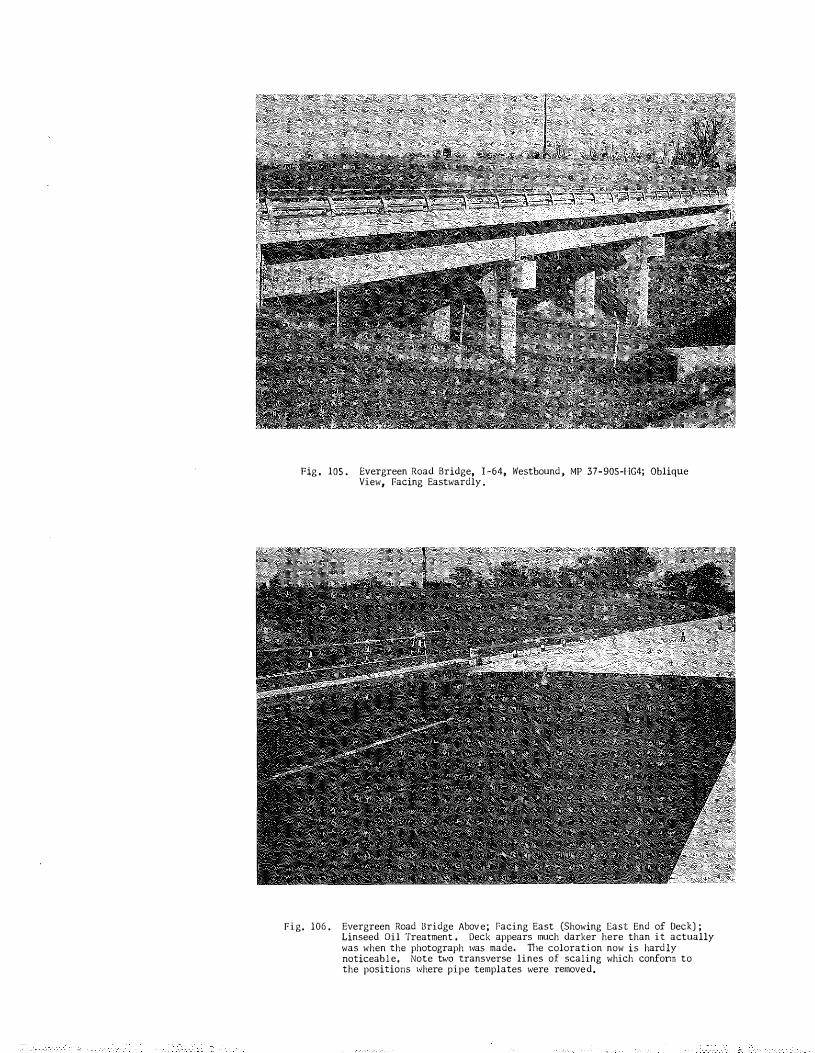
Fig , lOS . Evergreen Road Bridge, I -64, Westbound .. MP 37- 90S-I-!G4; Oblique View, Facing Eastwardly .
'
Fig. 106 . Evergreen Road Bridge Abov e ; Facing East (Showing East End of Deck) ; Linseed Oil Treatment . Deck appears much darker here than it actually was when the photograph \\las made. TI1e coloration now is hard ly noticeable, Note tvm transverse lines of scaling which confonn to the positions 1<1here pipe templates were removed,

Fig. 1 0 7 . South Benson Creek Bridge, I-64, Westbound , MP 37-905 - 3 ; Oblique View, Facing East\�ardly,
Fig, 108. South Benson Creek Bridge Above; Facing West; Guardian Chemical Company 1 s Clear Bond (Styrene-Buladiene) , Unfinished Here, Finished Later. Note scaling in left lane and transverse cracks conforming to construction joint and position of screeding templates .
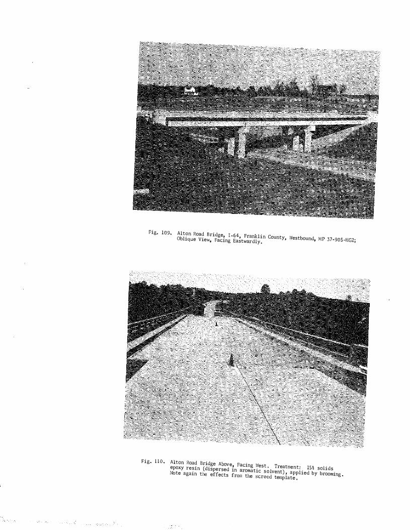
Fig, 109, Alton Road Bridge, I-64, Franklin County, Westbound, MP 37-905 -HGZ; Oblique View, Facing Eastwardly.
Fig. l l O , Alton Road Bridge Above, Facing \Vest , Treatment: 15% solids epoxy resin (dispersed in aromatic solvent) , applied by brooming . 1\bte again the effects from the screed template ,
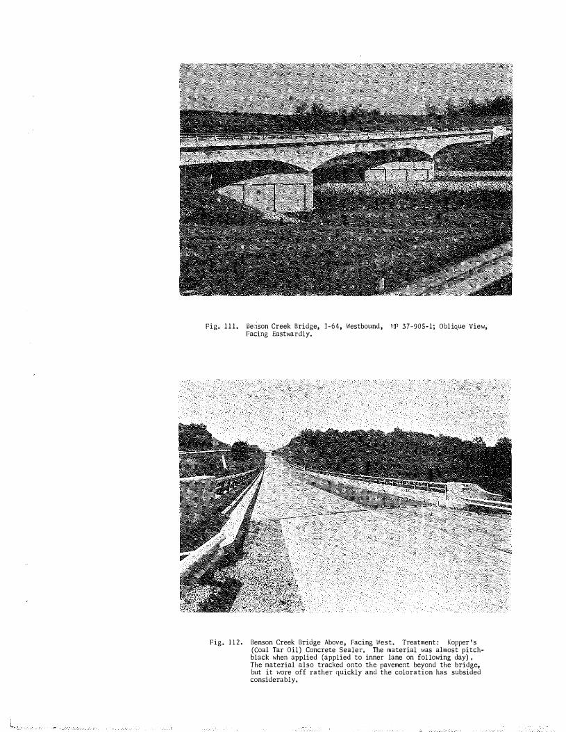
Fig. 1 1 1 . Berison Creek Bridge1 I-64, Westbound , MP 37-905-1; Obl ique View, Facing Eastwardly,
Fig. l l 2 . Benson Creek Bridge Above, racing \\lest. Treatment : Kopper ' s (Coal Tar Oil) Concrete Sealer, The material was almost pitchblack when applied (applied to inner lane on fol lowing day) , The material also tracked onto the pavement beyond the bridge, but it 1�ore off rather quickly and the coloration has subsided considerably.
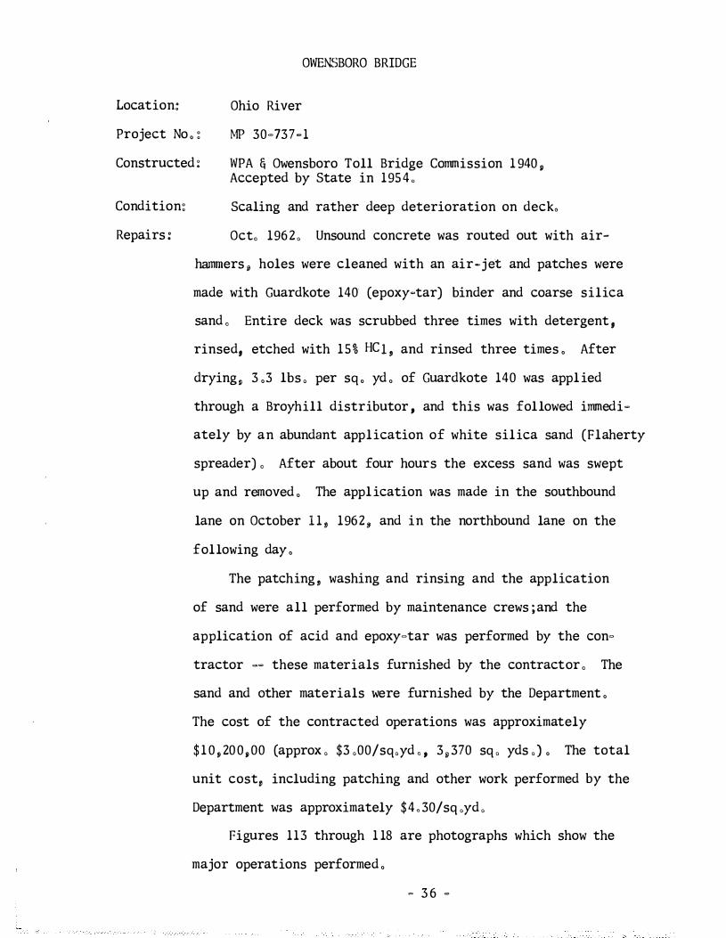
OWERSBORO BRIDGE
Location: Ohio River
Project No , : MP 30-737-1
Constructed : WPA & Owensboro Toll Bridge Commission 1 940 , Accepted by State in 195 4 ,
Condition:
Repairs :
Scaling and rather deep deterioration on deck,
Oct, 1962 , Unsound concrete was routed out with air-
hannners , holes were cleaned with an air-jet and patches were
made with Guardkote 140 (epoxy-tar) binder and coarse silica
sand , Entire deck was scrubbed three times with detergent ,
rinsed, etched with 15% HC ! , and rinsed three times , After
drying, 3 ,3 lbs , per sq , yd , of Guardkote 140 was appl ied
through a Broyhill distributor , and this was followed immedi-
ately by an abundant application of white silica sand (Flaherty
spreader) , After about four hours the excess sand was swept
up and removed , The appl ication was made in the southbound
lane on October 1 1 , 1962, and in the northbound lane on the
following day ,
The patching , washing and rinsing and the application
of sand were all performed by maintenance crews ;and the
application of acid and epoxy-tar was performed by the con
tractor -- these materials furnished by the contractor , The
sand and other materials were furnished by the Department ,
The cost of the contracted operations was approximately
$ 1 0 , 200,00 (approx , $3 ,00/sq,yd , , 3 , 370 sq , yds ,) , The total
unit cost, including patching and other work performed by the
Department was approximately $4 , 30/sq ,yd ,
Figures 113 through 1 18 are photographs which show the
major operations performed ,
- 3 6 -
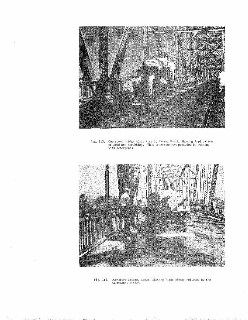
Fig. 1 1 3 . Owensboro Bridge (Ohio of Acid and Scrubbing , with detergent s .
River) ; Facing North; Showing Application Th.Ls treatment w.s preceded by \�ashing
Fig, 114. Owensboro Bridge 1 Above � ShOl-.'ing 1: i.rst Rinse; Fol loNed by the Additional !d.nses.

Pig. 115.
F i g , 1 1 6 .
Owensboro Bridge (Ohio River) � Facing North; Showing Acid-Treated, Rinsed, Dried Deck (Left Lane) Ready for Application of Epoxy-Tar Seal. Note extensive patching (epoxy-tar binder in patch material) , Patching was clone by maintenance crew; acid-treatment and application of resin was done by contractor�
0\vensboro Bridge; Application of Resiweld Guardkote 140 (H. B . Puller Company) � Through Mixing Distributor; Appl ication Rate, 3 , 3 Lbs, Per Sq. Yd , Note polyethylene sheet in foreground (for starting) , followed imneUiately by application oi sand ,
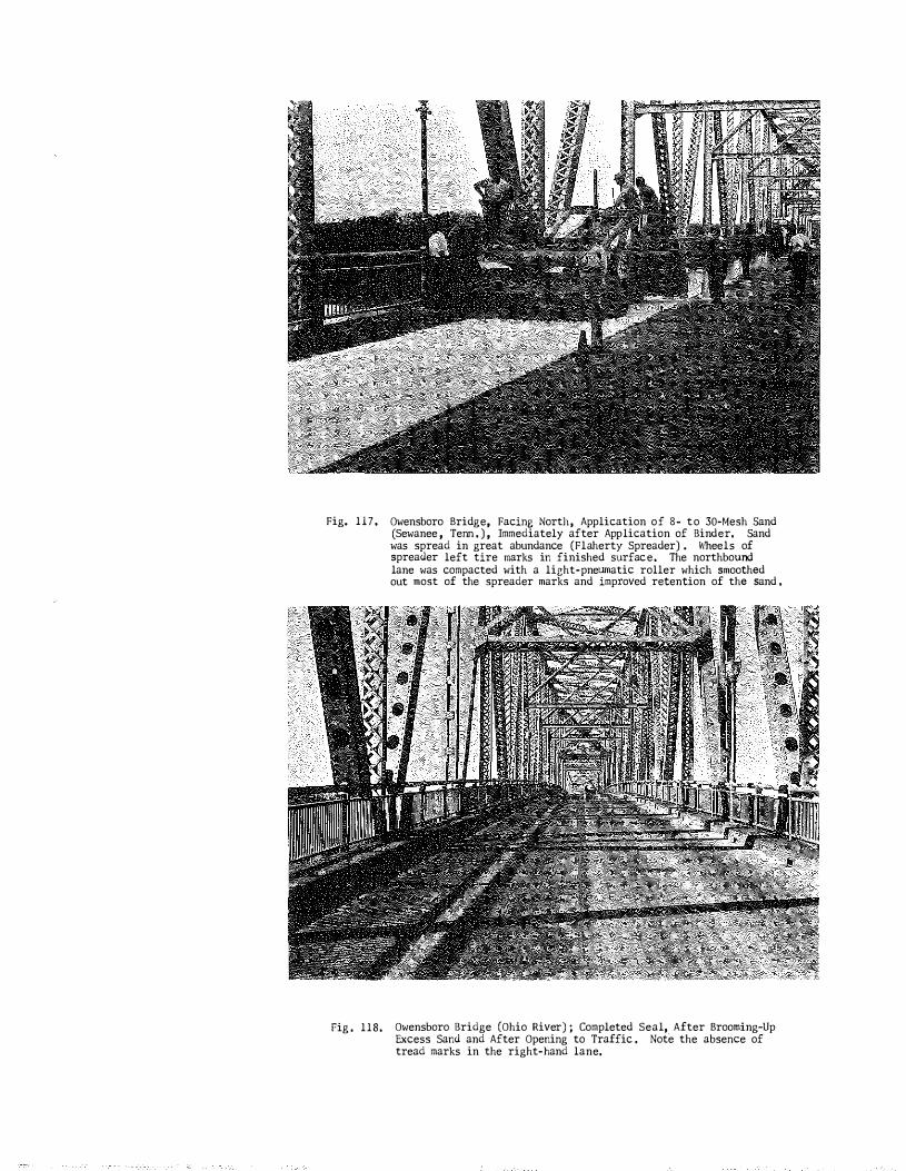
Fig. 117,
rig . 118.
Owensboro Bridge, Facing North, Application of 8 - to 30-Mesh Sand (Sewanee , Tenn . ) , Immediately after Application of Binder. Sand was spread in great abundance (Flaherty Spreader) . Wheels of spreader left tire marks in finished surface. The northbound lane was compacted with a light-pnelUllatic roller which smoothed out most of the spreader marks and improved retention of the sand ,
Owensboro Bridge (Ohio River) ; Completed Seal,. After Brooming-Up Excess Sand and After Opening to Traffic , Note the absence of tread marks in the right-hand lane,
BIG EDDY ROAD BRIDGE
Location:
Project No , :
!�64, Franklin County (Eastbound)
MP 37�905�HG8
Constructed : 1960
Type :
Treatment :
Reinforced concrete deck girder , three simple spans (See Fig , 1 19) ,
A rigid insulation of the polyether�type, self�extinguish�
ing urethane foam was applied to the underside of the bridge
deck , The urethane was applied by spraying on October 16·19,
1962, as shown in Fig , 1 21 , The accompanying photographs show
some of the spraying work and equipment , The material was
furnished and applied by the Dow Chemical Company ,
Instrumentation: Thermocouples were installed in the center span of the
bridge and in the approach slabs as indicated in Fig , 1 23 ,
These thermocouples are connected to a 12 �point tempeTature
(Micromax) recorder , The temperature data will be analyzed
by comparing differentials in temperature between the insulated
and un-insulated sections and the approaches ,
Objective To determine if the urethane foam is effective in:
of l , Equalizing deck and approach�slab temperatures so that
Study: icing occurs at both locations at approximately the same time.
and
2 , Reducing the number of freeze-thaw cycles to which the
bridge deck is subjected ,
A single temperature cycle, which was transcribed from
monitored records, is shown in Fig , 1 24 ,
- 37 -
� 38 �
Note: Treated with linseed oil , two coats , 12�5�62,
References ; "Urethane Foam Insulation for Bridge Decks , " by H , B , Brittan, Sr , Structural Specifications Writer, New York State Department of Public Works, Albany; Highway Research Abstracts , Vol , 31 , March, 1961 ,
Reports the use of foam insulation, Sept , 7 , 1960, southbound structure , West Main Street Separation, I -81 , Watertown, N , Y , ; report indicates a reduction in number of salt applications and in number of freeze-thaw cycles ,
"Progress Report of Effect of Insulating the Underside of a Bridge Deck , " by E , 0 , Axon and R, W , Crouch , Missouri State Highway Department , Presented at the 42nd Annual Meeting of the Highway Research Board , Jan , , 1963 ,
Urethane foam, 3/4 in, in thickness applied on one of twin bridges (No , A- 153, I�7o, Cooper County, Mo , , Nov , 1961) , Thermistors installed and temperature recorded thru April , 196 2 . Interpretation of data by the authors attribute great advantage to insulation -- that is, in reducing the number of cycles of freeze-thaw ,
"Research Planned to Study Effect of Insulation on Bridge Icing," by Louis M , Bj orn, Bridge Engineer , Vermont Department of Highways , Better Roads , Sept , , 1962, p , 31 ,
A report of planned work ; I -89, bridge over Winooski River in Montpelier; temperature recordings expected to be started October 1 , 196 2 ,

Fig. 1 1 9 . Big Eddy Road (or Old Johnson Road) , I-64, Eastbouni Bridge.
Fig. 120 , Equipment used to Apply Urethane Foam ; Air-Compressor , Mixing Pump (2-Component Resin) , Spray Gun and Lines . Drums of the resin components are in the truck, 10-16-62,
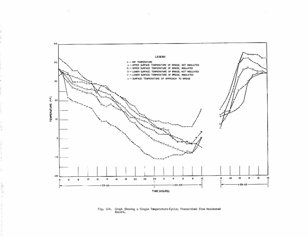
� ... w "' " !i "' "' .. "' "' 1-
50r---------------------------------------------------------------------------------------------------------,
40
30
10
-20 4 I_
. ,
LEGEND .o. - AIR TEMPERATURE
x - UPPER SURFACE TEMPERATURE OF BRIDGE, NOT INSULATED
0 - UPPER SURFACE TEMPERATURE OF BRIDGE, INSULATED "�-;;> ·
,----�. " � v � '\ x.._x......_ "'-v 0
� ....... )( ....... 17 o'\ - •-•-...,:::,�·- .,.,
0 - LOWER SURFACE TEMPERATURE OF BRIDGE, NOT INSULATED
'V - LOWER SURFACE TEMPERATURE OF BRIDGE, INSULATED
o - SURFACE TEMPERATURE OF APPROACH TO BRIDGE
'\o_ o_o � ·�. o....._ 'o-o
x.._ ...... ,. o_o_o o v '-..., "- • - '-o o-o-o\. ""-�� •
·, \ "b:--... \·...... I
· -. o- ...-o, '\o'-• •.._ \ -· -. 0 0 -m. ' '·
•
-. "a�., "-:-....
I \ \'o- • - � . ..... •
• \ �o-o-�,·- ---.·-·-...·-•-....,_,_, " 0-...o ' ,.�
0
6 8 10 12
•-•, '\, "-•..._ o...,•,o-o /
·-. 0 ....... . ., � •
" .............. / /1
" "0 "·-·-- ' "10 '·, o
, '-.-a".""' -"
14 16 18
1-23-63
'\. o....._o....._o x po ' •, -o-o •, -o-o •---."
'l!
)"o-v '\. tJ.-1!,-t:.
20
e......._"' ,..... e:. -'l> - ll -.l'.
22 24 2
TIME (HOURS)
4 6 8 10
1-24-63
-·-· "',
" . /; ...... t. · .......
o--"-o "-. -o-o . I /�7"
#l! ·;l! i I f / r •
8 10 12 14 16
1-29--63
Fig. 124. Graph Showing a Single Temperature-Cycle; Transcribed from Monitored Record.
18

�!
KENTUCKY RIVER BRIDGE
Location: I -64, Franklin County (Eastbound)
Proj ect No , : I -64-4 (8)54
Constructed : New (Refer to Fig , 4 ; Method of Finishing Concrete) ,
December 1 , 3 and 4, 196 2 , The deck was completed in
early October, Growing interest in protective treatments
Treatment :
arising perhaps from previous experimental applic�tions
immediately west of Frankfort on I -64 -- led the Department
to negotitate with the contractor for linseed oil treatment
of this bridge , Estimates based on experiences elsewhere
and on values suggested by the National Flaxseed Processors
Association ($0 ,03 per sq, yd , ,RMC; and $ 0 , 03 per sq , yd , for
application ; coverage of 40 to 50 sq , yds , per gal , of cut
oil ; 50% boiled linseed oil , 50% mineral spirits) were in
the order of $ 0 , 08 per sq , yd , This estimate was somewhat
conservative inasmuch as the two-coat appl ication cost of a
considerable quantity of work in I l linois in 1 96 2 was $0 ,08
per sq, yd , (see reference) , Failing to obtain a satisfactory
price for the work from the contractor, the Department elected
to apply the treatment with its pwn forces , In anticipation
of contract work of this kind, the fol lowing Special Provision
for Linseed Oil Protective Coating was drawn up ,
Figure 1 25 shows the application, by spray, to the deck
(deck was seemingly dry, although fog shrouds the background) ,
- 39 -

� 40 �
The plinth was coated by brushing , The rate of application
varied from slightly less than one gallon per SO sq, yds , to
as much as 1 , 8 gal , per 50 sq , yds , �� as needed to provide
ample coverage ,
The Big Eddy Road Bridge in the background of Fig , 1 25
and in Figs , 1 26 and 1 27 was treated at the same time as the
Kentucky River Bridge, Also, but not shown, the bridge over
old US 127 , now Ky , 420 (eastbound) , immediately west of the
Big Eddy Road Bridge was treated , Although treatments were
scheduled for each companion (westbound) bridge , cold rainy
weather delayed the work ,
Subsequent to the above treatments , bids were invited on
linseed oil protective treatments on the fol lowing projects
(Feb , 1 5 , 1963 , Letting) :
Perry County, F 102 (14) , SP 97�162; Campton�Hazard Road (Combs to Watertown) 8239 sq , yds ,
Anderson County, RS 3�871 ; Cedar Creek Bridge (Stringtown�Tyrone) 805 sq, yds ,
Fleming County, RS 35 �990; Hunt Oakley�Storey Branch Road, 327 sq , yds ,
Fayette County, ! �75�4 (14) 104 , SP 34�744 ; between Athens�Boonesboro Road and US 60, 6847 sq, yds ,
Whitley County, ! �75�1 (6) 4 , SP 1 18�350 ; Saxton� Pleasant View, 3500 sq , yds ,
References: "Linseed Oil Treatment on Bridge Structure," ' Henry E , Diers, Engr , of Maintenace, Il linois Division of Highways , Public Works , February, 1962, p , 115 ,
- 41 -
Approximately 1400 bridges were treated by Department forces in 1962; 58, 025 gallons of boiled l inseed oil used; appl ied in two coats (not more than 50 sq, yds ,/gallon; 0 ,02 gal ,/sq ,yd, ) ; labor cost $0 , 08 per sq, yd , ; material $0 ,033 per sq, yd , ; spec , requires concrete to be at least 14 days old ; adequate drying between coats (48 hours) ; traffic withheld until tack-free,
"Effects of De-Icing Chemicals on Structures," a Symposium HRB, Bulletin 323, 196 2 ,
"Protection of Existing Concrete Pavements from Salt and Calcium Chloride," Concrete Information Sheet (Highways & Municipal Bureau) , Portland Cement Association,
COMMONWEALTl: CF KEl\'l'UCKY DEPARTI.ffiNT OF R IGHWAYS
SPEC IJI� I'R�'! IS ICN
FOR
L I NSEED O IL PROTECTIVE COAT I NG
T h i s S pe c i a l P ro v i o i o n c o v e r s the m a t e r i a l r e qu i r e m e n t s a n d a p p l i c a t i o n p r o c e du r e s f o r a l i n s e e d o i l - p e t r o l e um s p i r i t s m i x t u r e t o b e u s e d a s a p r o t e c t i v e c o a t i n g f o r d e s i g n a t e d s u r · fac e s o f c o n c r e t e s t ru c t u r e s . Th i s S pe c i a l P ro v i s i o n s h a l l b e ap p l i c a b l e to I n d i v i d u a l p ro j e c t s o n l y w h e n l n d l c al e d o n t he p l a n s , i n the p r o po s a l s , o r i n b i d d i n g i n v i t at i o n s ,
I . DESCR I PT ION
T h i s wo r k s ha l l c o n s i s t o f t h e p r e parat i o n o f t he s u r f a c e s to be t r e a t e d , and f ur n i s h i n g a � d a p p l y i n g t h e ma t e r i a l s, in two a p p l i c a t i o n s , a s he r e i n a f t e r s p e c i f i e d .
I I . MATER I ALS
T h e pro t e c t i v e c o a t i n g m i xt u r e s ha l l c o n s i s t o f 5 0 p e r c e n t bo i l e d l i n s e e d a n d 5 0 p e r c e n t p e t r o l e um s p i r i t s b y v o lume , T h e l i n s e e d o i l s ha l l c o m p l y w i t h A . A . S , H .O . S pe c i f i c a t i o n M 1 2 6 , e x c e p t t h a t t h e s p e c i f i c grav i t y s h a l l b e no t l e s s t han 0 . 9 3 2 . T h e p e t r o l eum s p i r i t s ( m i n e r a l s p i r i t s ) s ha l l com p l y w i t h A . A . S , H . C . S p e c i f i c a t i o n M 1 2 8 .
I I I . APPL I CAT ION
T h e pro t e c t i v e c o a t i n g s ha l l be a p p l i e d t o t h e e n t i r e t o p s u r f a c e o f t he b r i d g e d e c k , t he f a c e s a n d t o p s u r f ac e s o f c u r b s , t h e t o p s u r f a c e s o f s i de w a l k s , a n d t h e to p and i n s i d e v e r t i c a l s u r f a c e s o f p l i n t h s o r s i d e w a l k p a r a pe t s .
T h e c o n c r e t e s h a l l be � t l e a s t 1 4 d a y s o l d b e f o r e t h e f i r s t c o a t i n g i s a p p l i e d ,
The c o n c r e t e s u r f ac e s s ha l l h a v e a t l e a s t a 48 hour d r y i n g p e r i o d j u s t p r i o r t o t h e a p p l i c a t i o n o f t h e m i xt u r e a n d s ha l l be c l e a n e d o f a l l o i l , g r ime , a n d l o o s e part i c l e s wh i c h w i l l p r e v e n t t h e m i xt u r e f r o m p e n e t r a t i n g t h e c o n c re t e . Imme d i a t e l y b e f o re t h e ap p l i c a t i o n o f t h e m i xt u r e , a n a i r b l a s t s h a l l b e d i r e c t e d o v e r t h e s u r f ac e s to b e t r e a t e d s o t ha t a l l d u s t w i l l b e r e m o v e d ,
E a c h c o a t s ha l l b e a p p l i e d b y s p r a y i n g a t a r a t e o f a pp l i c a t i o n n o t t o e x c e e d 5 0 s qu a r e y a r d s pe r ga l l o n o f the m i xt u r e . The s pr a y n o z z l e s s h a l l be w i t h i n 1 8 i n c h e s o f t he c o n c r e t e or a s o t he r w i s e d i r e c t e d b y t h e En g i n e e r , Ha n d m e t h o d s m a y b e p e r m i t t e d , The i n t e r i o r o f t h e e q u i p m e n t s h a l l b e t h o r o u gh l y c l e a n e d p r i o r t o p l ac i n g t he m i xt u r e t h e r e i n ,
- 4 2 -

P a g e 2 o f 2
Un l e s s o t h e r w i s e d i r e c t e d b y t h e E n g i ne e r , t h e tempe r a t u r e o f the c o nc r e t e and a i r s h a l l b e 5 0 d e g r e e s F . o r h i g h e r at the t im e o f ap p l i c a t i o n .
The s e c o n d appl i c a t i o n o f t h e pro t e c t i v e c o a t i n g m i x t u r e s h a l l n o t b e m a d e u n t i l t he c o n c r e t e , i n t he o p i n i o n o f t he Eng i n e e r , h a s r e ga i n e d i t s d r y a p p e ar a n c e .
Cau t io n : A s t h e l i n s e e d o i l - m i n e r a l s p i r i t s m i xture h a s a l o w f l a s h po i nt and i s r e ad i l y f l amma b l e , a l l f i r e s , i n c l u d i n g c i ga r e t t e s a n d s pa rk s , s h a l l be c a r e f u l l y g u a r d e d a ga i n s t .
When p r ac t i c a b l e , t h e t r e a t e d s u r f a c e s s h a l l b e c l o s e d t o a l l t r a f f i c unt i l t h e c o nc r e t e h a s r e g a i n e d i t s d r y a p p e a r an c e .
IV • MEASUREMENT
T h e a c t u a l a r e a c o a t e d a s s p e c i f i e d s h a l l b e m e a s u r e d i n s qu a r e y a r d s �
V . PAYMENT
T h e quan t i t i e s t h u s m e a s u r e d s h a l l b e p a i d f o r a t t h e . u n i t p r i c e b i d p e r s qu a r e y a r d fo r "Pro t e c t iv e C o a t i n g , • wh i c h payme n t s h a l l b e f u l l c o m pe n s at i o n f o r p r e p a r a t i o n o f t h e s u r f ac e , fur n i s h i n g a n d ap p l y i ng t h e m a te r i a l s , and f o r fu r n i s h i n g a l l l a bo r , e qu i pment , a n d i n c i de n t a l s n e c e s s ar y t o c o m p l e t e the w o r k ,
APPROVED /Jpt; .Z?" /fGZ.
D: -H . ' BRA STATE HIGHWAY ENGIN
• 43 •
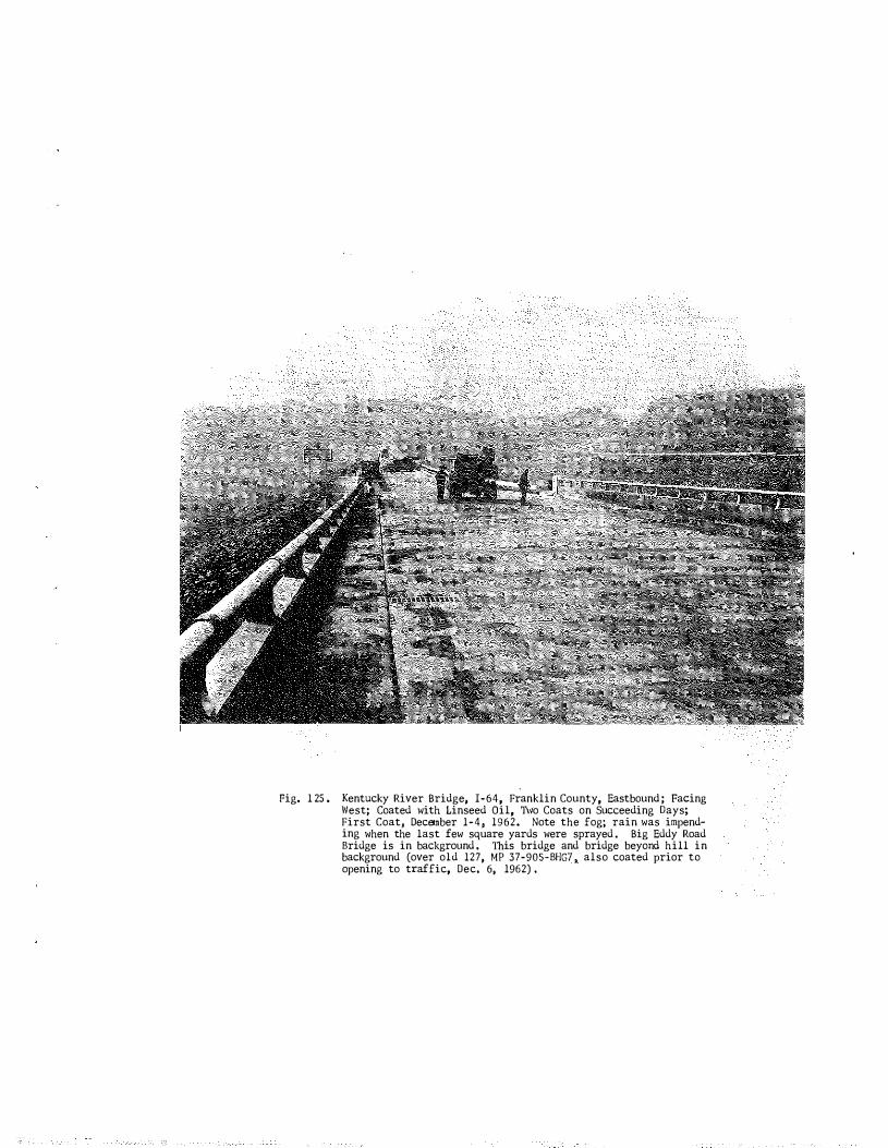
Fig. 1 25 . Kentucky River Bridge, I-64, Franklin County, Eastbound ; Facing West; Coated with Linseed Oil, n�o Coats on Succeeding Days; First Coat, December 1-4, 1962. Note the fog; rain was impend� ing when the last few square yards were sprayed . Big Eddy Road Bridge is in background . This bridge and bridge beyond hill in background (over old 127, MP 37-905-BHG? � also coated prior to opening to traffic, Dec. 6, 1962) .
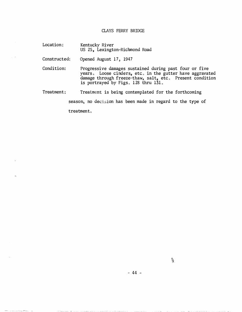
CLAYS FERRY BRIDGE
Location : Kentucky River US 25 , LexingtonoRichmond Road
Constructed: Opened August 1 7 , 1947
Condition:
Treatment :
Progressive damages sustained during past four or five years , Loose cinders, etc , in the gutter have aggravated damage through freezeothaw, salt, etc , Present condition is portrayed by Figs , 1 28 thru 131 ,
Treatment is being contemplated for the forthcoming
season, no decision has been made in regard to the type of
treatment,
�' ;>;<,
0 44 �
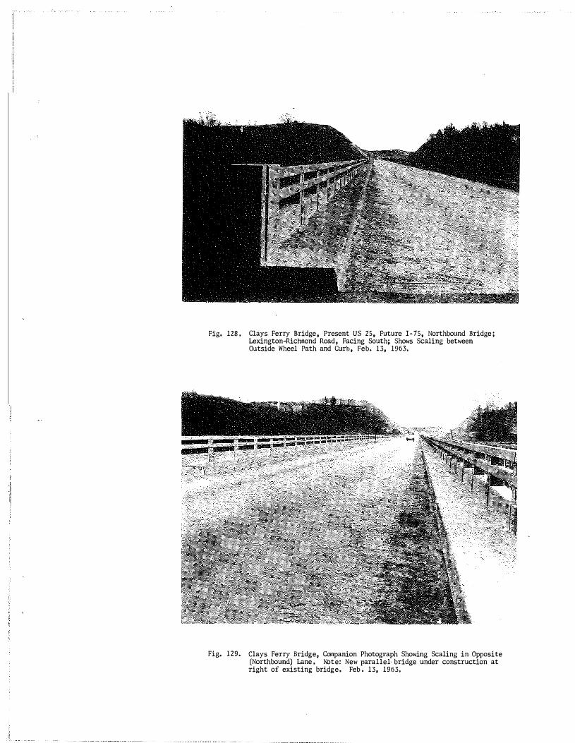
Fig. 128 .
Fig. 129.
Clays Ferry Bridge, Present US 25, Future l-75, Northbound Bridge ; Lexington-Richmond Road, Facing South; Shows Scaling between Outside Wheel Path and Curb, Feb. 13, 1963.
Clays Ferry Bridge, Companion Photograph Showing Scaling in Opposite (Northbound) Lane . Note: New parallel· bridge under construction at right of existing bridge. Feb , 13, 1963,

Fig. 130. Clays Ferry Bridge, US 25, Lexington-Richmond ROad, A close�up view showing scaling at expansion joint and gutter line. Debris, which appears in the background, has been swept away" in the foreground disclosing the persistence of aggravating moisture there.
Fig. 131. Clays Ferry Bridge. Close-up view of impending failure of deck, near south end of bridge.
HEATING BRIDGE DECKS
Heating bridge decks to prevent icing and to remove snow is an
alluring idea not only from the viewpoint of eliminating hazardous con
dition, but also from the viewpoint of eliminating damage to a bridge
which otherwise might arise from freeze-thaw and de-icing salts, Two
experimental installations of electrical heating elements in bridge decks
have been made during the past two to three years, Brief annotations to
these and to two other references to heating pavements follow in their
chronological order:
"Snow and Ice Removal by Heating Cables," Feature Article, Electrical Construction and Maintenance, Vol, 58, March, 1959, pp, 85-8 ,
Heating cables were installed at 18 toll plazas, Dec, 23, 1958, on the Northern Illinois Tollways; each lane for a distance of 84 ft,; each installation used 1,183 ft, of No, 19 AWG wire; cables were taped to mesh-mats, imbedded 2 in, in concrete; manually operated switches (no thermostats); 208-volt, 3-phase system,
Note: Home-type units for installation in driveways and sidewalks are manufactured by Electromode Division of Commercial Controls, Corp,, 570 Culver Rd,, Rochester, N,Y,9 Easy-Heat, Inc,, Lakeville9 Indiana, and Chromelox, Electric Heat, Edwin L, Wiegard Company, 7500 'Thomas Blvd, Pittsburgh 8, Pa,
"Sloping Driveway's Snow Melting System Assures Snowfree, Slipfree Pavem�nt!" John Rudberg, M,E,, Ellerbe & Co,;.,!,!,eat:!Eg Piping and Air Condi�10n1ng, Vol, 31, Oct, 1959, pp, 112�113,
Some 18,000 sq, ft, of driveway at the Central Office Building of the Minnesota Department of Highways, St, Paul -3/4 in, piping, 12 in, on centers, were buried 2-1/4 in, in concrete pavement; ethylene glycol (antifreeze) is cir· culated through the piping system from a steam-heated exchanger inside the building; the system is controlled manually,
- 45 -
� 46 �
'
Note: A somewhat similar system was installed earlier at the Greyhound Bus Terminal in New York City,
"Research Study, Ice Prevention on Bridge Decks. Interim Report," by M, D, Shelby, Re.search Engineer, and W, B, Ledbetter, Design Engineer, Texas Highway Department, January, 1962,
Ha1f�inch diameter metal tubing was placed between the upper and lower layers of reinforcing steel; No, 19 AWG (insulated with glass yarn, silicone rubber, and tinned, copper braid) was threaded through the conduit; bridges are 120 ft, long; City View Drive, on US 287, northwest of Wichita Falls [F 119(11), Ull9(12)]; power provided ranged from 5 to 20 watts per sq, ft,; imbedment ranged from 1 to 3 inches; 74 amps at 490 volts ( 119 KWH); installation completed Jan, 20, 1961; no final conclusions drawn,
"Experimental Roadway Heating Project, Passaic River Bridge Approach �
Routes US 1 & 9, Newark, New Jersey," by D, J, Henderson, Supervising Electrical Engineer, Bureau of Electrical Operations, New Jersey State Highway Department; presented at the 42nd Annual Meeting of the Highway Research Board, January, 1963,
Cites prior uses of electric heating cables: 1) the Mound in Edinburgh, Scotland, and 2) concrete deck of an overpass in Aberdeen, South Dakota (18 in, wide wheel tracks), Parallel U�loops 710 ft, long laid longitudinally on fill�section of bridge approach; 133 ft, continuous S� loops (1000 ft, cable) laid on first span of bridge; three� phase, 450 volts at 600 KVA used; cables were about 4 in, apart; cemented to pavement with asphalt joint�sealer; surfaced with leveling course and sand�asphalt; total coat of installation. including transformers and switches, $2,19 per sq, ft,. heating elements estimated to cost about $1,10 per sq, ft,; monthly charge for 600 KVA service, $400,00; estimated use. 125 hrs, per winter; cost of heating 67,7 hrs, $2, 958,00; designed for 35 to 40 watts per sq, ft,, to melt one inch of snow per hour,

SUMMARY
None of the major repair efforts thus far has proven to be inef
fective except the sand-asphalt treatment on the Clark Memorial Bridge.
Even in that instance, the sand-asphalt performed admirably as a wearing
surface -- it simply was not effective in abating the deterioration of the
underlying concrete, Of course, only four other major deck repairs have
been attempted, i,e, the Lake Cumberland Bridge (Ky. 90), the Danville
Bridge (US 150), the Owensboro Bridge (Ohio River), and the old Russell
Fork Bridge in Pike County, The Danville Bridge, as previously mentioned,
has been patched but remains unsealed, A need for some repair on the
Clays Ferry Bridge seems imminent, and perhaps other bridges are being
considered by the Division of Maintenance, Notwithstanding unforseen
calamitous performances, and relying somewhat upon performance records
elsewl1ere, the epoxy-seal seems to offer the best means presently available
to restore and further protect deteriorating decks, The particular epoxy
system remains a matter of choice and economy inasmuch as the so-called
flexibilized epoxies are available in the polysulfide formulations as
well as in the amine-type formulations and the epoxy-tar formulations.
The choice of patch material also remains optional between epoxy mortars
and latex-modified portland cement mortars, although Embeco, non-shrink
type mortars or gunite might be considered alternatively, The most
significant factors adversely affecting the performance of patches seems
to be shrinkage of the patch material and failure to prepare square-cut
margins around the patch area,
- 47 -

� 48 -
Preventive treatments such as linseed oil, styrene solutions,
etc, are nominal in cost and seem to offer some re-assurance against
premature scaling, The use of preventive treatments on new work, of
course. presumes that the concrete is susceptible to scaling -� an in
admissible presumption, according to some authorities, if the concrete
has been placed properly, Nevertheless, until confirming evidence can
be established to the effect that improvements in concreting practices
can wholly alleviate the problem of scaling, it seems advisable to
pursue a preventive treatment program,