Embed Size (px)
Citation preview
METRIC MIL-STD-188-125-2 3 March 1999
DEPARTMENT OF DEFENSEDEPARTMENT OF DEFENSEINTERFACE STANDARDINTERFACE STANDARD
HIGH-ALTITUDE ELECTROMAGNETIC PULSE (HEMP) PROTECTIONFOR GROUND-BASED C4I FACILITIES PERFORMING CRITICAL,
TIME-URGENT MISSIONS
PART 2TRANSPORTABLE SYSTEMS
AMSC N/A AREA TCSS
DISTRIBUTION STATEMENT A. Approved for public release; distribution is unlimited.
Downloaded from http://www.everyspec.com
MIL-STD-188-125-2
ii
HIGH-ALTITUDE ELECTROMAGNETIC PULSE (HEMP) PROTECTIONFOR GROUND-BASED C4I FACILITIES PERFORMING CRITICAL,TIME-URGENT MISSIONS, PART 2: TRANSPORTABLE SYSTEMS
F O R E W O R D
1. This military standard is approved for use by all Departments and Agencies of theDepartment of Defense (DoD).
2. Originally, Military Standard 188 (MIL-STD-188) covered technical standards for tacticaland long-haul communications, but later evolved through revisions (MIL-STD-188A, MIL-STD-188B) into a document applicable to tactical communications only (MIL-STD-188C).
3. The Defense Information Systems Agency (DISA) published DISA circulars (DISAC),promulgating standards and engineering criteria applicable to the long-haul Defense Communi-cation System and to the technical support of the National Military Command System.
4. As a result of a Joint Chiefs of Staff action, standards for all military communications arenow being published in a MIL-STD-188 series of documents. The MIL-STD-188 series issubdivided into a MIL-STD-188-100 series, covering common standards for tactical and long-haul communications; a MIL-STD-188-200 series, covering standards for tactical communi-cations only; and a MIL-STD-188-300 series, covering standards for long-haul communicationsonly. Emphasis is being placed on developing common standards for tactical and long-haulcommunications, published in the MIL-STD-188-100 series.
5. This two-part document contains technical requirements and design objectives for high-altitude electromagnetic pulse (HEMP) protection of ground-based systems and facilities that arenodes in HEMP-hardened networks for performing critical and time-urgent command, control,communications, computer, and intelligence (C4I) missions. Part 1 of the document addressesHEMP hardening for fixed facilities; this Part 2 addresses transportable systems. Therequirements are stringent, in order to avoid both damage and functional upsets that preventmission accomplishment within operationally prescribed timelines. The standards apply uniformlyto all systems and facilities in the end-to-end chain, since disruption of a single node may result innetwork failure.
6. Performance, acceptance test, and verification test requirements are contained in the body ofthe standard. HEMP-unique acceptance and verification test techniques are provided inAppendices A, B, C, and D.
7. Implementation of MIL-STD-188-125-1 is supported by MIL-HDBK-423, "High-AltitudeElectromagnetic Pulse (HEMP) Protection for Fixed and Transportable Ground-Based Facilities,
Downloaded from http://www.everyspec.com
MIL-STD-188-125-2
iii
Volume I: Fixed Facilities." The handbook also includes planning, management, logistics, anddata requirements for HEMP protection acquisition programs and hardness maintenance/ hardnesssurveillance requirements for operational systems and facilities. Some sections of MIL-HDBK-423, Volume I, are also applicable to MIL-STD-188-125-2. References to sections of MIL-HDBK-423 are made within this standard, where applicable.
8. Beneficial comments (recommendations, additions, deletions) and any pertinent data whichmay be of use in improving this document should be addressed to: Defense Threat ReductionAgency/TEL-NSSE, 6801 Telegraph Road, Alexandria, VA 22310-3398, by using theStandardization Document Improvement Proposal (DD Form 1426) appearing at the end of thisdocument or by letter.
Downloaded from http://www.everyspec.com
MIL-STD-188-125-2
CONTENTS
PARAGRAPH PAGE
iv
FOREWORD ......................................................................................... ii
1. SCOPE ................................................................................................... 11.1 Purpose.............................................................................................. 11.2 Scope................................................................................................. 11.3 Applications ....................................................................................... 11.4 Objectives .......................................................................................... 1
2. APPLICABLE DOCUMENTS.............................................................. 22.1 General .............................................................................................. 22.2 Government documents...................................................................... 22.2.1 Specifications, standards, and handbooks............................................ 22.2.2 Other Government documents, drawings, and publications ................. 32.3 Non-Government publications ............................................................ 32.4 Order of precedence ........................................................................... 4
3. DEFINITIONS ....................................................................................... 53.1 Acronyms used in this standard........................................................... 53.2 Sources for definitions........................................................................ 73.3 Definitions.......................................................................................... 83.3.1 Aperture point-of-entry (POE) ........................................................... 83.3.2 Conductive POE................................................................................. 83.3.3 Continuous wave (CW) immersion ..................................................... 83.3.4 Corrective maintenance ...................................................................... 83.3.5 Electromagnetic barrier ...................................................................... 83.3.6 Electromagnetic closure ..................................................................... 93.3.7 Electromagnetic stress ........................................................................ 93.3.8 HEMP acceptance test ....................................................................... 93.3.9 HEMP hardness ................................................................................. 93.3.10 HEMP hardness assurance.................................................................. 93.3.11 HEMP hardness configuration baseline ............................................... 93.3.12 HEMP hardness critical item (HCI) .................................................... 93.3.13 HEMP hardness critical process (HCP)............................................... 103.3.14 HEMP hardness maintenance (HM).................................................... 103.3.15 HEMP hardness maintenance and hardness surveillance (HM/HS) ...... 103.3.16 HEMP hardness surveillance (HS) ...................................................... 103.3.17 HEMP hardness surveillance/reverification testing .............................. 103.3.18 HEMP protection measures ................................................................ 10
Downloaded from http://www.everyspec.com
MIL-STD-188-125-2
CONTENTS
PARAGRAPH PAGE
v
3.3.19 Intrasite cable ..................................................................................... 103.3.20 Long-line cable................................................................................... 103.3.21 Long-line protection module (LLPM)................................................. 103.3.22 Low-risk HEMP hardening................................................................. 113.3.23 Main barrier electrical POE protective device ..................................... 113.3.24 Mission-critical equipment (MCE)...................................................... 113.3.25 Norton equivalent circuit or Norton source......................................... 113.3.26 Penetration entry area......................................................................... 113.3.27 Performance degradation.................................................................... 113.3.28 Point-of-entry (POE).......................................................................... 113.3.29 POE protective device or POE treatment............................................ 113.3.30 Preventive maintenance ...................................................................... 123.3.31 Primary special electrical POE protective device................................. 123.3.32 Protected volume ............................................................................... 123.3.33 Pulsed current injection (PCI)............................................................. 123.3.34 Residual internal stress ....................................................................... 123.3.35 Retrofit HEMP hardening................................................................... 123.3.36 Secondary special electrical POE protective device............................. 123.3.37 Shielded enclosure leak detection system (SELDS)............................. 123.3.38 Special protective measures................................................................ 123.3.39 Special protective volume................................................................... 133.3.40 Subsystem HEMP shield..................................................................... 133.3.41 Threat-level illumination..................................................................... 133.3.42 Verification testing ............................................................................. 133.3.43 Vulnerability threshold (of an equipment) ........................................... 133.3.44 Waveguide below cutoff (WBC)......................................................... 133.3.45 Waveguide-below-cutoff array............................................................ 13
4. GENERAL REQUIREMENTS............................................................. 144.1 General .............................................................................................. 144.1.1 HEMP protection overview................................................................ 144.1.2 Integration with related requirements.................................................. 144.2 Hardness program overview ............................................................... 144.3 HEMP hardening design..................................................................... 154.3.1 Subsystem HEMP shields ................................................................... 154.3.2 POEs.................................................................................................. 154.3.3 External cable plant ............................................................................ 154.3.4 Mission-critical equipment.................................................................. 15
Downloaded from http://www.everyspec.com
MIL-STD-188-125-2
CONTENTS
PARAGRAPH PAGE
vi
4.3.4.1 MCE within the electromagnetic barrier.............................................. 164.3.4.2 MCE outside the electromagnetic barrier ............................................ 164.3.5 HEMP-hardened electrical power ....................................................... 164.3.6 Special protective measures................................................................ 164.4 HEMP testing..................................................................................... 164.4.1 Quality assurance program ................................................................. 174.4.2 Acceptance testing ............................................................................. 174.4.3 Verification testing ............................................................................. 174.5 HM/HS .............................................................................................. 174.5.1 HM/HS program development............................................................ 174.5.2 HM/HS program implementation........................................................ 17
5. DETAILED REQUIREMENTS............................................................ 185.1 HEMP protection topology ................................................................ 185.1.1 Transportable system topology ........................................................... 185.1.2 Electromagnetic barrier topology........................................................ 185.1.3 Penetration entry area......................................................................... 195.1.4 External electrical cabling ................................................................... 205.1.4.1 Intrasite cabling .................................................................................. 205.1.4.2 Long-line cabling................................................................................ 225.2 Transportable system grounding ......................................................... 225.2.1 Equipotential ground plane................................................................. 225.2.2 Grounding to the subsystem HEMP shields......................................... 225.2.3 Long-line protection module grounding .............................................. 235.3 Subsystem HEMP shields ................................................................... 235.3.1 Shielding effectiveness........................................................................ 235.3.2 Shield configuration............................................................................ 235.3.3 Shield production quality assurance .................................................... 235.3.4 Shield acceptance testing .................................................................... 245.3.4.1 Subsystem shield modifications........................................................... 245.4 Architectural POEs............................................................................. 245.4.1 HEMP protection for architectural POEs............................................ 245.4.2 Personnel entryways and exits ............................................................ 245.4.2.1 Shielded doors.................................................................................... 245.4.2.2 Shielded vestibules ............................................................................. 245.4.3 Equipment accesses............................................................................ 245.4.4 Acceptance testing for architectural POE protective measures ............ 255.5 Mechanical POEs ............................................................................... 26
Downloaded from http://www.everyspec.com
MIL-STD-188-125-2
CONTENTS
PARAGRAPH PAGE
vii
5.5.1 HEMP protection for mechanical POEs.............................................. 265.5.2 Piping POEs....................................................................................... 265.5.3 Ventilation POEs................................................................................ 265.5.4 Acceptance testing for mechanical POE protective devices ................. 285.6 Structural POEs ................................................................................. 285.6.1 HEMP protection for structural POEs ................................................ 285.6.2 Acceptance testing for structural POE treatments ............................... 285.7 Electrical POEs and long-line protection modules............................... 295.7.1 Electrical POEs .................................................................................. 295.7.1.1 HEMP protection for electrical POEs ................................................. 295.7.1.2 Intrasite power line POE protective device requirements..................... 295.7.1.3 Intrasite control, signal, and data line POE protective
device requirements..................................................................... 385.7.1.4 Antenna line POE protective device requirements ............................... 395.7.1.4.1 Core conductor injection requirements for receive-only
antenna line POE protective devices ............................................ 395.7.1.4.2 Core conductor injection requirements for transmit
antenna line POE protective devices ............................................ 395.7.1.4.3 Shield injection requirements for antenna line POE
protective devices........................................................................ 405.7.1.5 Acceptance testing of electrical POE protective devices...................... 405.7.2 Long-line protection modules ............................................................. 405.7.2.1 General requirements for LLPMs........................................................ 415.7.2.2 Power line LLPM requirements .......................................................... 415.7.2.3 Control, signal, and data line LLPM requirements............................... 415.7.2.4 Acceptance testing of LLPMs............................................................. 465.8 Special protective measures................................................................ 465.8.1 MCE outside the subsystem electromagnetic barriers .......................... 465.8.1.1 RF communications antennas outside the subsystem
electromagnetic barriers .............................................................. 475.8.2 MCE that is inside a subsystem electromagnetic barrier and
fails verification testing................................................................ 475.8.3 Special protective volumes ................................................................. 475.8.3.1 Special protective volumes for piping POEs........................................ 475.8.3.1.1 Special waveguide requirements ......................................................... 475.8.3.1.2 Special protective barriers for piping POEs......................................... 495.8.3.2 Special protective volumes for electrical POEs ................................... 49
Downloaded from http://www.everyspec.com
MIL-STD-188-125-2
CONTENTS
PARAGRAPH PAGE
viii
5.8.3.2.1 Primary special electrical POE protectivedevice requirements..................................................................... 49
5.8.3.2.2 Secondary special electrical POE protectivedevice requirements..................................................................... 49
5.8.3.2.3 Special protective barriers for electrical POEs..................................... 495.8.3.2.4 MCE in special protective volumes..................................................... 505.8.4 Acceptance testing for special protective measures ............................. 505.8.4.1 Special protective measures for MCE ................................................. 505.8.4.2 Special protective barriers .................................................................. 505.9 Reliability and maintainability ............................................................. 505.10 Safety and human engineering............................................................. 505.11 Testability .......................................................................................... 515.12 Corrosion control ............................................................................... 515.13 Configuration management................................................................. 515.14 Verification testing ............................................................................. 515.14.1 CW immersion testing ........................................................................ 515.14.2 PCI verification testing ....................................................................... 525.14.3 Threat-level illumination testing.......................................................... 535.14.4 Verification testing of special protective measures .............................. 535.14.4.1 Verification testing of MCE hardened with special
protective measures..................................................................... 535.14.4.2 Verification testing of special protective barriers................................. 545.15 HM/HS program requirements ........................................................... 545.15.1 Hardness surveillance/reverification test procedures............................ 545.15.2 Maintenance and inspection procedures .............................................. 545.15.3 Supply support requirements .............................................................. 555.15.4 Training requirements......................................................................... 555.15.5 Technical data .................................................................................... 555.15.6 Delivery ............................................................................................. 555.15.7 Implementation................................................................................... 55
6. NOTES ................................................................................................... 566.1 Intended use....................................................................................... 566.2 Issues of DoDISS............................................................................... 566.3 Subject term (key word) listing........................................................... 56
Downloaded from http://www.everyspec.com
MIL-STD-188-125-2
CONTENTS
FIGURE PAGE
ix
1 Typical transportable system barrier topology..................................... 192 Penetration entry area placement ........................................................ 203 External cable descriptions ................................................................. 214 Minimum HEMP shielding effectiveness requirements (measured
in accordance with procedures of Appendix A) .......................... 235 Typical vestibule entryway.................................................................. 256 Typical waveguide-below-cutoff piping POE protective devices. ........ 277 Typical waveguide-below-cutoff array ventilation POE
protective device........................................................................ 288 Typical electrical POE protective device............................................. 309 Typical special protective volumes...................................................... 48
TABLE
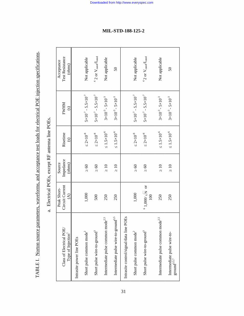
I Norton source parameters, waveforms, and acceptance test loads forelectrical POE injection specifications ........................................ 31
II Maximum allowable residual internal response norms forelectrical POE injection specifications ........................................ 35
III Norton source parameters, waveforms, and acceptance test loads forLLPM injection specifications .................................................... 42
IV Maximum allowable residual response norms for LLPMinjection specifications ............................................................... 44
V Verification test program options........................................................ 52
APPENDIX
A SHIELDING EFFECTIVENESS (SE) TEST PROCEDURESFOR TRANSPORTABLE GROUND-BASED SYSTEMS ... 57
B PULSED CURRENT INJECTION (PCI) TEST PROCEDURESFOR TRANSPORTABLE GROUND-BASED SYSTEMS ... 71
Downloaded from http://www.everyspec.com
MIL-STD-188-125-2
CONTENTS
APPENDIX PAGE
x
C CONTINUOUS WAVE (CW) IMMERSION TEST PROCEDURESFOR TRANSPORTABLE GROUND-BASED SYSTEMS ... 106
D THREAT-LEVEL ILLUMINATION TEST PROCEDURESFOR TRANSPORTABLE GROUND-BASED SYSTEMS ... 122
CONCLUDING MATERIAL....................................................................................... 137
Downloaded from http://www.everyspec.com
MIL-STD-188-125-2
1
1. SCOPE
1.1 Purpose. This standard establishes minimum requirements and design objectives forhigh-altitude electromagnetic pulse (HEMP) hardening of transportable1 ground-based systemsthat perform critical, time-urgent command, control, communications, computer, and intelligence(C4I) missions. Systems required to fully comply with the provisions of the standard will bedesignated by the Joint Chiefs of Staff, a Military Department Headquarters, or a MajorCommand.
1.2 Scope. This standard prescribes minimum performance requirements for low-riskprotection from mission-aborting damage or upset due to HEMP threat environments defined inMIL-STD-2169. The standard also addresses minimum testing requirements for demonstratingthat prescribed performance has been achieved and for verifying that the installed protectionmeasures provide the operationally required HEMP hardness for the completed system. If theprescribed testing results in any hardware damage or functional upsets, the operational authorityfor the system will make the determination whether the observed event is mission aborting.
1.3 Applications. This standard defines the design and testing criteria for specificallydesignated transportable ground-based systems in HEMP-hardened, critical, time-urgent C4Inetworks. Such systems include subscriber terminals and data processing centers, transmittingand receiving communications stations, and relay systems. The standard applies to both newsystems and modifications of existing systems. Although only local portions of systeminterconnects are addressed, it is assumed that survivable long-haul communications paths, fiber-optic links, or other hardened interconnects between systems will be provided as required formission accomplishment.
1.4 Objectives. Survivable C4I capabilities are essential to a credible military deterrent.This standard supports nuclear survivability objectives by providing a standardized, low-riskprotection approach for transportable ground-based systems in HEMP-hardened C4I networks.These uniform requirements ensure balanced HEMP hardening for all critical systems and facilitiesin the network.
1 This part of the standard addresses transportable systems only. A transportable ground-based C4I system, for purposes of thisstandard, consists of equipment in shelters that provide survivable C4I capabilities at a relocatable deployment site. HEMPhardening requirements for fixed ground-based facilities are contained in MIL-STD-188-125-1.
Downloaded from http://www.everyspec.com
MIL-STD-188-125-2
2
2. APPLICABLE DOCUMENTS
2.1 General. The documents listed in this section are specified in sections 3, 4, and 5 of thisstandard. This section does not include documents cited in other sections of this standard orrecommended for additional information or as examples. While every effort has been made toensure the completeness of this list, document users are cautioned that they must meet allspecified requirements documents cited in sections 3, 4, and 5 of this standard, whether or notthey are listed.
2.2 Government documents.
2.2.1 Specifications, standards, and handbooks. The following specifications, standards, andhandbooks form a part of this document to the extent specified herein. Unless otherwisespecified, the issues of these documents are those listed in the effective issue of the Department ofDefense (DoD) Index of Specifications and Standards (DoDISS) and supplement thereto (see6.2).
STANDARDS
FEDERAL
FED-STD-1037 – Telecommunications: Glossary of Telecommunication Terms
DEPARTMENT OF DEFENSE
MIL-STD-100 – Engineering Drawing PracticesMIL-STD-188-125-1 – High-Altitude Electromagnetic Pulse (HEMP)
Protection for Ground-Based C4I FacilitiesPerforming Critical, Time-Urgent Missions, Part 1: Fixed Facilities
MIL-STD-2169 – High-Altitude Electromagnetic Pulse (HEMP)Environment (U) (document is classified Secret)
HANDBOOKS
DEPARTMENT OF DEFENSE
MIL-HDBK-419 – Grounding, Bonding and Shielding for Electronic Equipment and Facilities
Downloaded from http://www.everyspec.com
MIL-STD-188-125-2
3
MIL-HDBK-423 – High-Altitude Electromagnetic Pulse (HEMP)Protection for Fixed and TransportableGround-Based Facilities, Volume I: Fixed Facilities
(Unless otherwise indicated, copies of the above specifications, standards, and handbooks areavailable from the Standardization Document Order Desk, 700 Robbins Avenue, Building 4D,Philadelphia, PA 19111-5094. Requests for MIL-STD-2169 should indicate that the document isclassified, and contractor requests require endorsement by the DoD contracting activity.)
2.2.2 Other Government documents, drawings, and publications. The following otherGovernment documents, drawings, and publications form a part of this standard to the extentspecified herein. Unless otherwise specified, the issues are those cited in the solicitation.
PUBLICATIONS
JOINT PUB 1-02 – Department of Defense Dictionary of Military and Associated Terms
FORMS
DD Form 2639 – Hardness Critical Label
DD Form 2640 – Hardness Critical Tag
(Copies of documents required by contractors in connection with specific acquisition functionsshould be obtained from the contracting activity or as directed by the contracting officer.)
2.3 Non-Government publications. The following document forms a part of this standard tothe extent specified herein. Unless otherwise specified, the issues of the documents which areDoD adopted are those listed in the issue of the DoDISS cited in the solicitation. The issues ofdocuments not listed in the DoDISS are the issues of the documents cited in the solicitation (see6.2).
ANSI C63.14 – American National Standard Dictionary for Technologies of Electromagnetic Compatibility (EMC), Electromagnetic Pulse (EMP), and Electrostatic Discharge (ESD)
Downloaded from http://www.everyspec.com
MIL-STD-188-125-2
4
(Applications for copies should be addressed to the Institute for Electrical and ElectronicsEngineers [IEEE], 445 Hoes Lane, Post Office Box 1331, Piscataway NJ 08855-1331).
2.4 Order of precedence. In the event of a conflict between the text of this document andthe references cited herein, the text of this document takes precedence. Nothing in this document,however, supersedes applicable laws and regulations unless a specific exemption has beenobtained.
Downloaded from http://www.everyspec.com
MIL-STD-188-125-2
5
3. DEFINITIONS
3.1 Acronyms used in this standard. The acronyms used in this standard are defined asfollows:
a. A – Ampere
b. ac – Alternating Current
c. C4I – Command, Control, Communications, Computer, and Intelligence
d. cm – Centimeter
e. CW – Continuous Wave
f. dB – Decibel
g. dBm – Power in dB referred to one milliwatt
h. dc – Direct Current
i. DoD – Department of Defense
j. DoDISS – Department of Defense Index of Specifications and Standards
k. DR – Dynamic Range
l. EMP – Electromagnetic Pulse
m. ESA – Electric Surge Arrester
n. F/O – Fiber Optics
o. ft – Foot
p FWHM – Full-Width at Half-Maximum Amplitude
q. GHz – Gigahertz
r. GPIB – General Purpose Interface Bus
Downloaded from http://www.everyspec.com
MIL-STD-188-125-2
6
s. HCI – Hardness Critical Item
t. HCP – Hardness Critical Process
u. HEMP – High-Altitude Electromagnetic Pulse
v. HM – Hardness Maintenance
w. HM/HS – Hardness Maintenance/Hardness Surveillance
x. HS – Hardness Surveillance
y. Hz – Hertz
z. IAW – In Accordance With
aa. IEEE – Institute of Electrical and Electronics Engineers
bb. in – Inch
cc. kA – Kiloampere
dd. kHz – Kilohertz
ee. LLPM – Long-Line Protection Module
ff. m – Meter
gg. mA – Millampere
hh. MCE – Mission-Critical Equipment
ii. MHz – Megahertz
jj. MR – Measurement Range
kk. ms – Millisecond
ll. ns – Nanosecond
mm. PCI – Pulsed Current Injection
Downloaded from http://www.everyspec.com
MIL-STD-188-125-2
7
nn. POE – Point-of-Entry
oo. RF – Radio Frequency
pp. s – Second
qq. SE – Shielding Effectiveness
rr. SEM – Shielding Effectiveness (Magnetic)
ss. SEPW – Shielding Effectiveness (Plane Wave)
tt. SER – Shielding Effectiveness (Resonant Range)
uu. SELDS – Shielded Enclosure Leak Detection System
vv. SNR – Signal-to-Noise Ratio
ww. TEMPEST – A term used to describe a methodology for controlling radiated andconducted emanations of classified information
xx. V – Volt
yy. WBC – Waveguide below cutoff
zz. µs – Microsecond
aaa. Ω – Ohm
3.2 Sources for definitions. Sources for definitions of terms used in this standard, in orderof decreasing priority, are as follows:
a. FED-STD-1037, “Telecommunications: Glossary of Telecommunication Terms,”
b. JOINT PUB 1-02, “Department of Defense Dictionary of Military and AssociatedTerms,”
Downloaded from http://www.everyspec.com
MIL-STD-188-125-2
8
c. MIL-STD-188-125-1, “High-Altitude Electromagnetic Pulse (HEMP) Protection forGround-Based C4I Facilities Performing Critical, Time-Urgent Missions, Part 1: FixedFacilities,”
d MIL-HDBK-423, “High-Altitude Electromagnetic Pulse (HEMP) Protection for Fixedand Transportable Ground-Based C4I Facilities, Volume I: Fixed Facilities,”
e. ANSI C63.14, “American National Standard Dictionary for Technologies ofElectromagnetic Compatibility (EMC), Electromagnetic Pulse (EMP), and ElectrostaticDischarge (ESD),”
f. MIL-HDBK-419, “Grounding, Bonding and Shielding for Electronic Equipment andFacilities,”
g. MIL-STD-100, “Engineering Drawing Practices.”
3.3 Definitions.
3.3.1 Aperture point-of-entry (POE). An intentional or inadvertent hole, crack, opening, orother discontinuity in the HEMP shield surface. Intentional aperture POEs are provided forpersonnel and equipment entry and egress and for fluid flow (ventilation and piped utilities)through the electromagnetic barrier.
3.3.2 Conductive POE. An electrical wire or cable or other conductive object, such as ametal rod, that passes through the electromagnetic barrier. Conducting POEs are also calledpenetrating conductors.
3.3.3 Continuous wave (CW) immersion. A test method for measuring the electromagneticresponses induced on an electromagnetic barrier and other items of interest (e.g., cables orconduits) illuminated by a CW electric or magnetic field.
3.3.4 Corrective maintenance. All unscheduled maintenance actions. HEMP correctivemaintenance action is undertaken when excessive degradation or failure of a hardness criticalitem is detected, to restore the HEMP protection to a satisfactory condition and level ofperformance. Corrective maintenance includes removal of the defective item, repair orreplacement, reassembly, and checkout of the completed work.
3.3.5 Electromagnetic barrier. The topologically closed surface created to prevent or limitHEMP fields and conducted transients from entering the enclosed space. The electromagneticbarrier consists of the HEMP shield and POE treatments, and it encloses the protected volumeand special protective volumes, if required.
Downloaded from http://www.everyspec.com
MIL-STD-188-125-2
9
3.3.6 Electromagnetic closure. A treatment to prevent excessive electromagnetic fieldleakage at an aperture POE. Examples of closure techniques at a seam between two metal platesinclude welding, brazing, or soldering and metal-to-metal contact under pressure applied with amechanical fastening.
3.3.7 Electromagnetic stress. A voltage, current, charge, or electromagnetic field that actson an item of equipment. If the electromagnetic stress exceeds the vulnerability threshold of theequipment, mission-aborting damage or upset may occur.
3.3.8 HEMP acceptance test. An acceptance test of a system, subsystem, or componentperformed to ensure that specified HEMP performance characteristics have been met. HEMPacceptance tests, conducted near the conclusion of a hardening production or installation contract,are tests for the purpose of demonstrating that at least minimum performance requirements of theHEMP protection measures have been achieved before the unit is accepted by the Governmentfrom the contractor.
3.3.9 HEMP hardness. A quantitative description of the resistance of a system orcomponent to temporary or permanent malfunction or degraded performance induced by HEMP.HEMP hardness is achieved through adhering to appropriate design specifications and is verifiedby one or more test and analysis techniques.
3.3.10 HEMP hardness assurance. Procedures and activities performed during theconstruction or production phase to confirm that the end product meets the HEMP hardnessdesign specifications. Hardness assurance includes those aspects of quality assurance that dealwith hardening component and subassembly testing, acceptance testing, and initial verificationtesting to confirm that design specifications have been met.
3.3.11 HEMP hardness configuration baseline. The functional and physical characteristicsof the HEMP protection measures achieved in the “as-built” system and documented in the systemdrawings and technical manuals.
3.3.12 HEMP hardness critical item (HCI). An item at any assembly level havingperformance requirements for the purpose of providing HEMP protection. Nuclear HCIs provideprotection from environments produced by a nuclear event or are specially designed to operateunder nuclear weapon (device)-derived stresses. HEMP HCIs are the elements of the HEMPprotection. A hardness critical assembly is a top-level definable unit of HEMP HCIs and othercomponents, such as mounting hardware and terminal posts, that may not be hardness critical.
Downloaded from http://www.everyspec.com
MIL-STD-188-125-2
10
3.3.13 HEMP hardness critical process (HCP). A process, specification, or procedure thatmust be followed exactly to ensure that the associated HCI attains its required performance.
3.3.14 HEMP hardness maintenance (HM). Preventive maintenance (e.g., adjustments orcleaning) and corrective maintenance (e.g., repairs or replacements) on the HEMP protectionmeasures or the HCIs and assemblies. These HM activities are intended to eliminate faults or topreserve specified HEMP protection performance levels.
3.3.15 HEMP hardness maintenance and hardness surveillance (HM/HS). The combinedpreventive maintenance, inspection, test, and repair activities accomplished on a HEMP-protectedoperational system to ensure that HEMP hardness is retained throughout the system life cycle.HM/HS, along with hardness assurance and hardness configuration management, constitute atotal hardness assurance, maintenance, and surveillance program.
3.3.16 HEMP hardness surveillance (HS). Inspections and tests of the HEMP protectionmeasures or the HCIs and assemblies. These HS activities are intended to observe and monitorthe condition and performance of the hardening elements and to detect faults.
3.3.17 HEMP hardness surveillance/reverification testing. Testing conducted at prescribedintervals during the operational phase of the system life cycle for evaluating whether the HEMPprotection measures continue to provide the required HEMP hardness. HS/reverification testrequirements are established in the technical manual. They typically require repetition of some orall of the test procedures from the original verification test program.
3.3.18 HEMP protection measures. The electromagnetic barrier and all special protectivemeasures installed for the purpose of hardening the mission-critical equipment against the HEMPenvironment.
3.3.19 Intrasite cable. An external system cable, outside the subsystem electromagneticbarriers, that meets the length and routing restrictions of this standard and is used to interconnectsubsystems or to connect a subsystem to equipment outside the barriers.
3.3.20 Long-line cable. An external cable, outside the subsystem electromagnetic barriers,used to connect the transportable system to equipment located beyond the deployment site.Subsystem and equipment interconnecting cables that do not meet the length and routingrestrictions of this standard are also designated as long-line cables.
3.3.21 Long-line protection module (LLPM). A HEMP protective device provided toisolate the intrasite cable plant and mission-critical subsystems and equipment from transientsinduced on long-line cables by the HEMP threat environment.
Downloaded from http://www.everyspec.com
MIL-STD-188-125-2
11
3.3.22 Low-risk HEMP hardening. A hardening technique that features a high-qualityelectromagnetic barrier with minimized and protected POEs. Virtually all mission-criticalcommunications-electronics and support equipment are placed in the protected volume enclosedby the barrier and operate in a relatively benign electromagnetic environment, isolated from theexternal HEMP stresses. The low-risk approach results in a well-defined HEMP protectionconfiguration with inherent testability.
3.3.23 Main barrier electrical POE protective device. A protective device installed on anelectrical conductor that penetrates from the system exterior, through the HEMP shield, and intothe protected volume. Main barrier protective devices must meet the performance requirementsof this standard.
3.3.24 Mission-critical equipment (MCE). All equipment required to directly support acritical mission, success or failure of which could affect the outcome of battle. In the context ofthis standard, MCE refers to all communications-electronics and support equipment that must beprotected in order to perform critical trans- and post-HEMP attack missions.
3.3.25 Norton equivalent circuit or Norton source. A circuit, consisting of a current sourcein parallel with an impedance, that has equivalent characteristics to those of the represented circuitover the operating range of interest.
3.3.26 Penetration entry area. That area of the electromagnetic barrier where longpenetrating conductors (such as an electrical power feeder) and piping POEs are concentrated.
3.3.27 Performance degradation. Changes in one or more performance characteristics of acomponent or assembly, such that it no longer operates within the required functional range.
3.3.28 Point-of-entry (POE). A location on the electromagnetic barrier where the shield ispenetrated and HEMP energy may enter the protected volume unless an adequate POE protectivedevice is provided. POEs are classified as aperture POEs or penetrating conductors according tothe type of penetration. They are also classified as architectural, mechanical, structural, orelectrical POEs according to the engineering discipline in which they are usually encountered.
3.3.29 POE protective device or POE treatment. The protective measure used to prevent orlimit HEMP energy from entering the protected volume at a POE. Common POE protectivedevices include waveguides below cutoff and closure plates for aperture POEs, and filters andelectric surge arresters on penetrating conductors. The three categories of electrical POEprotective devices installed on penetrating conductors are main barrier POE protective devices,primary special POE protective devices, and secondary special POE protective devices.
Downloaded from http://www.everyspec.com
MIL-STD-188-125-2
12
3.3.30 Preventive maintenance. Scheduled maintenance actions. These actions areperformed on a regular basis. Preventive maintenance includes scheduled adjustments, cleaning,and replacement of items with limited lifetimes.
3.3.31 Primary special electrical POE protective device. A protective device installed on anelectrical conductor that penetrates from the system exterior, through the HEMP shield, into aspecial protective volume. A primary special POE protective device is designed to provide themaximum attenuation possible without interfering with the normal operational electrical signalsthat are routed on the penetrating conductor.
3.3.32 Protected volume. The three-dimensional space enclosed by the electromagneticbarrier, but not including those spaces that are within special protective volumes.
3.3.33 Pulsed current injection (PCI). A test method for measuring performance of a POEprotective device on a penetrating conductor. A HEMP threat-relatable transient is injected onthe penetrating conductor at a point outside the electromagnetic barrier, and the residual internaltransient stress is measured inside the barrier.
3.3.34 Residual internal stress. The electromagnetic voltages, currents, charges, or fieldsthat originate from the HEMP environment and penetrate into the protected volume afterattenuation by elements of the electromagnetic barrier.
3.3.35 Retrofit HEMP hardening. An action taken to modify in-service HEMP protectiveequipment. Retrofit HEMP hardening is the installation or substantial upgrade of the HEMPprotection measures for an existing system or equipment.
3.3.36 Secondary special electrical POE protective device. A protective device installed onan electrical conductor that penetrates from a special protective volume into the main protectedvolume. It is used only when necessary to augment the attenuation provided by the primaryspecial POE protective device and the connected equipment. The total attenuation through theprimary special POE protective device, the connected equipment, and the secondary special POEprotective device must meet the performance requirements of this standard.
3.3.37 Shielded enclosure leak detection system (SELDS). Any of a class of commerciallyavailable instruments designed for checking shielding effectiveness in the magnetic field testregime. Most of these instruments operate at one or more discrete frequencies, often of the orderof 100 kHz.
3.3.38 Special protective measures. All HEMP hardening measures required in addition toimplementation of the electromagnetic barriers. Special protective measures are necessary for
Downloaded from http://www.everyspec.com
MIL-STD-188-125-2
13
MCE outside the barrier, for MCE that are within the protected volume and experience damageor upset during verification testing, and in cases requiring a special protective volume.
3.3.39 Special protective volume. A HEMP-protected space within a subsystemelectromagnetic barrier, where electromagnetic stresses due to HEMP may exceed the residualinternal stress limits for the protected volume. The special protective barrier may be a separateshield with protected penetrations; more commonly, shielded cables or conduits and equipmentcabinets and closed piping systems are used to provide the needed electromagnetic isolation fromthe protected volume.
3.3.40 Subsystem HEMP shield. The continuous conductive housing that substantiallyreduces the coupling of HEMP electric and magnetic fields into the subsystem protected volume.The subsystem HEMP shield is part of the electromagnetic barrier.
3.3.41 Threat-level illumination. Exposure of systems or equipment to simulated HEMPfields with characteristics similar to the environment defined in MIL-STD-2169. Threat-levelillumination tests are conducted as part of the system hardness verification program.
3.3.42 Verification testing. Tests conducted for demonstrating that the installed HEMPprotection measures provide the required HEMP hardness. These tests are performed after theproduction and acceptance testing are complete and after the equipment is installed andfunctioning, to determine if the operational system suffers mission-aborting damage or upset dueto simulated HEMP excitations. Verification is normally a Government-conducted test and is notpart of a system production contract.
3.3.43 Vulnerability threshold (of an equipment). The minimum stress level that causes theequipment to suffer definite degradation. In the context of this standard, the vulnerabilitythreshold is the minimum electromagnetic stress that causes mission-aborting damage or upset.
3.3.44 Waveguide below cutoff (WBC). A metallic waveguide whose primary purpose is toattenuate electromagnetic waves at frequencies below the cutoff frequency (rather thanpropagating waves at frequencies above cutoff). The cutoff frequency is determined by thetransverse dimensions and geometry of the waveguide and properties of the dielectric material inthe waveguide.
3.3.45 Waveguide-below-cutoff array. An assembly of parallel waveguides below cutoff,with adjacent cells usually sharing common cell walls. A waveguide-below-cutoff array is usedwhen the area of the shield aperture required to obtain adequate fluid flow is larger than thepermissible area of a single waveguide below cutoff.
Downloaded from http://www.everyspec.com
MIL-STD-188-125-2
14
4. GENERAL REQUIREMENTS
4.1 General.
4.1.1 HEMP protection overview. The need exists for uniform and effective hardening,hardness verification, and hardness maintenance/hardness surveillance of transportable ground-based C4I systems that require network interoperability during and after exposure to HEMPenvironments. In critical time-urgent applications where some momentary upsets, as well asdamage, may be mission-aborting, the hardening requirements include high-integrity shielding,POE protection, and special protective measures. Since normal operational experience may notindicate the condition of the HEMP protection measures, thorough verification testing andhardness maintenance/hardness surveillance after deployment are necessary.
4.1.2 Integration with related requirements. Elements of the HEMP protection can servemultiple purposes. For example, the electromagnetic barrier can also be used to meet emanationssecurity requirements. HEMP-hardening measures shall be integrated with those of otherelectromagnetic requirements, such as electromagnetic interference/electromagnetic compatibility,lightning protection, and TEMPEST, and with treatments for other hardening requirements. Theperformance requirements in this standard are for HEMP protection only; increases in therequired performance may be needed for protection from other electromagnetic environments, inaddition to HEMP.
4.2 Hardness program overview. Hardness programs2 for transportable ground-basedsystems being HEMP hardened in accordance with (IAW) requirements of this standard shallimplement DoD acquisition policy and procedures. Design and engineering, fabrication,installation, and testing activities shall be organized to accomplish the following objectives:
a. To provide a HEMP-protected system design based on verifiable performancespecifications,
b. To verify hardness levels through a cost-effective program of testing and analysis,
c. During the acquisition process, to develop a maintenance/surveillance program thatsupports the operational phase of life-cycle HEMP hardness,
2 HEMP planning, analysis, test procedures, and test reporting documentation, and requirements for hardness maintenance andhardness surveillance program development and execution are described in MIL-HDBK-423. While the handbook specificallyaddresses fixed facilities, much of the programmatic information is also applicable to transportable systems.
Downloaded from http://www.everyspec.com
MIL-STD-188-125-2
15
d. To establish the HEMP configuration baseline, consisting of documentation of thefunctional and physical characteristics of the HEMP protection measures, and baselineperformance data.
4.3 HEMP hardening design. System protection against the HEMP threat environmentspecified in MIL-STD-2169 shall be achieved by enclosing the MCE in electromagnetic barriersand with special protective measures, as required. If the transportable system is made up ofseparate transportable elements (herein referred to as subsystems), the MCE in each of thesubsystems shall be enclosed in an independent electromagnetic barrier. Each subsystemelectromagnetic barrier shall consist of a HEMP shield and protective devices for all POEs.Special protective measures shall be implemented in special cases where HEMP hardness cannotbe achieved with an electromagnetic barrier alone (see 4.3.6). Reliability, maintainability,configuration management, safety and human engineering, testability, corrosion control andprevention, and standard drawing practices shall be incorporated into the HEMP protectiondesign.
4.3.1 Subsystem HEMP shields. The subsystem HEMP shields shall be continuousconductive enclosures that meet or exceed shielding effectiveness requirements of this standard(see 5.3.1). The shields are normally constructed of metal, such as steel, copper, or aluminum.Other materials may be used if they can provide the required shielding effectiveness and are fullycompatible with the POE protective treatments and grounding requirements.
4.3.2 POEs. The number of subsystem shield POEs shall be limited to the minimumrequired for operational, life-safety, and habitability purposes. All POEs shall be HEMP protectedwith POE protective devices that satisfy performance requirements of this standard (see 5.4through 5.7).
4.3.3 External cable plant. The external cable plant shall consist of intrasite and long-linecables that are not enclosed within electromagnetic barriers and are, therefore, exposed to theunattenuated HEMP threat environment. Intrasite cables are those that comply with length androuting restrictions specified in this standard (see 5.1.4.1). All other external cables are long-linecables and shall connect to the MCE through long-line protection modules (see 5.1.4.2). Mission-critical external cables shall be HEMP protected using special protective measures, as required.
4.3.4 Mission-critical equipment. All equipment required to perform critical time-urgentmissions during and after HEMP attack shall be designated as mission-critical equipment. MCEmay include such items as communications-electronics equipment, data processing subsystems,
Downloaded from http://www.everyspec.com
MIL-STD-188-125-2
16
command/control equipment, local portions of hardened interconnects3, and critical supportsubsystems such as power generation/distribution and environmental control.
4.3.4.1 MCE within the electromagnetic barrier. All MCE that will operate satisfactorilyand compatibly within the subsystem shields shall be installed inside an electromagnetic barrierthat meets the performance requirements of this standard. No HEMP-unique performancecharacteristics are required in design or selection of mission-critical equipment that will be housedwithin a barrier.
4.3.4.2 MCE outside the electromagnetic barrier. All MCE that must be placed outside anelectromagnetic barrier, including mission-critical antenna subsystems and external mission-criticalcables, shall be provided with special protective measures (see 5.8.1) as required to ensurehardness in the HEMP threat environment.
4.3.5 HEMP-hardened electrical power. The system shall be provided with HEMP-hardened electrical power generation and distribution capability sufficient to perform trans- andpost-attack missions, without reliance upon commercial electrical power sources.
4.3.6 Special protective measures. Special protective measures shall be implemented incases where HEMP hardness cannot be achieved with an electromagnetic barrier alone.Additional shielding, transient suppression/attenuation devices, and equipment-level protectionshall be provided as required to achieve HEMP hardness. The three categories of cases requiringspecial protective measures are as follows:
a. MCE that must be located outside an electromagnetic barrier and, therefore, are notprotected by the barrier (see 5.8.1),
b. MCE that are enclosed within an electromagnetic barrier and experience mission-aborting damage or upset during verification testing, even though the barrier elements satisfy allperformance requirements (see 5.8.2),
c. Special protective volumes and barriers to provide supplementary isolation when POEprotective devices cannot satisfy barrier requirements without interfering with system operation(see 5.8.3).
4.4 HEMP testing. The HEMP testing program shall demonstrate that hardnessperformance requirements have been satisfied and that the required HEMP hardness has beenachieved. This program shall include quality assurance testing during system production and 3 Although they are not included within the scope of this document, HEMP-hardened interconnects and survivable long-haulcommunications circuits to other hardened systems in the network must be provided as required for mission accomplishment.
Downloaded from http://www.everyspec.com
MIL-STD-188-125-2
17
equipment installation, acceptance testing for the electromagnetic barriers and special protectivemeasures, and verification testing of the completed and operational system. All data acquiredduring the HEMP testing program shall be stored in a manner to facilitate test reporting andsubsequent use of data as an HM/HS database.
4.4.1 Quality assurance program. A quality assurance program shall be implemented duringsystem production and assembly to demonstrate that the HEMP protection materials andcomponents comply with performance requirements of this standard. The quality assurance testprocedures and results shall be documented and retained for use as baseline configuration andperformance data for the HM/HS program.
4.4.2 Acceptance testing. Acceptance of the HEMP protection measures shall be based onsuccessful demonstrations of compliance with hardness performance requirements of thisstandard. HEMP acceptance tests of the electromagnetic barriers and special protective measuresshall be conducted after all related fabrication work has been completed. Acceptance testprocedures and results shall be documented and retained for use as baseline configuration andperformance data.
4.4.3 Verification testing. After completion of the HEMP protection measures andinstallation/operational checks of the subsystem equipment, HEMP hardness of the system shall beverified through a program of tests and supporting analysis. The verification program shallprovide a definitive statement on the HEMP hardness of mission functions of the system undertest. All deficiencies identified by the verification testing shall be corrected, retested, and shownto provide the required hardness. Verification test procedures and results shall be documentedand retained for use as baseline configuration and performance data.
4.5 HM/HS.
4.5.1 HM/HS program development. Hardness maintenance and hardness surveillanceconsiderations shall be included in the system planning, design, and production phases to facilitatelife-cycle survivability and the development of an effective HM/HS program. The HM/HSprogram shall be designed to maintain the HEMP protection at a level of performance that meetsthe requirements in this standard.
4.5.2 HM/HS program implementation. During the verification phase, baseline data shall beobtained for the HM/HS program. The HM/HS program shall be fully implemented in theoperation and support phase of the system life cycle. Effectiveness of the HM/HS program formaintaining the HEMP protection subsystem performance at the required level shall beperiodically reviewed, and program revisions shall be made when required.
Downloaded from http://www.everyspec.com
MIL-STD-188-125-2
18
5. DETAILED REQUIREMENTS
5.1 HEMP protection topology.
5.1.1 Transportable system topology. A transportable system shall consist of one or moreelements (subsystems) that must be placed in separate volumes to be transportable and that mustbe interconnected to function together to perform the operational mission. Subsystems that arecritical for performing trans- and post-HEMP attack missions shall be HEMP protected. Typicalsubsystems may be as follows:
a. Mobile electric power subsystem,
b. Power distribution subsystem,
c. Communications equipment subsystem,
d. Automated data processing subsystem,
e. Command and control subsystem,
f. Other special purpose subsystems, as defined by mission requirements.
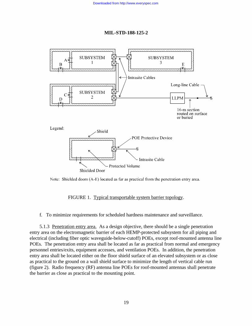
5.1.2 Electromagnetic barrier topology. An electromagnetic barrier, consisting of a HEMPshield and POE protective devices, shall be constructed for each mission-critical subsystem of thetransportable system. A typical barrier topology is shown on figure 1. The HEMP shields andPOE protective devices shall be configured to accomplish the following technical requirements:
a. To enclose all MCE, except equipment that will not function properly if placed within theprotected volume,
b. To comply with the shield and POE performance requirements specified in this standard,
c. To minimize the number of POEs,
d. To minimize requirements for special protective measures,
e. To facilitate HEMP acceptance and verification testing,
Downloaded from http://www.everyspec.com
MIL-STD-188-125-2
19
FIGURE 1. Typical transportable system barrier topology.
f. To minimize requirements for scheduled hardness maintenance and surveillance.
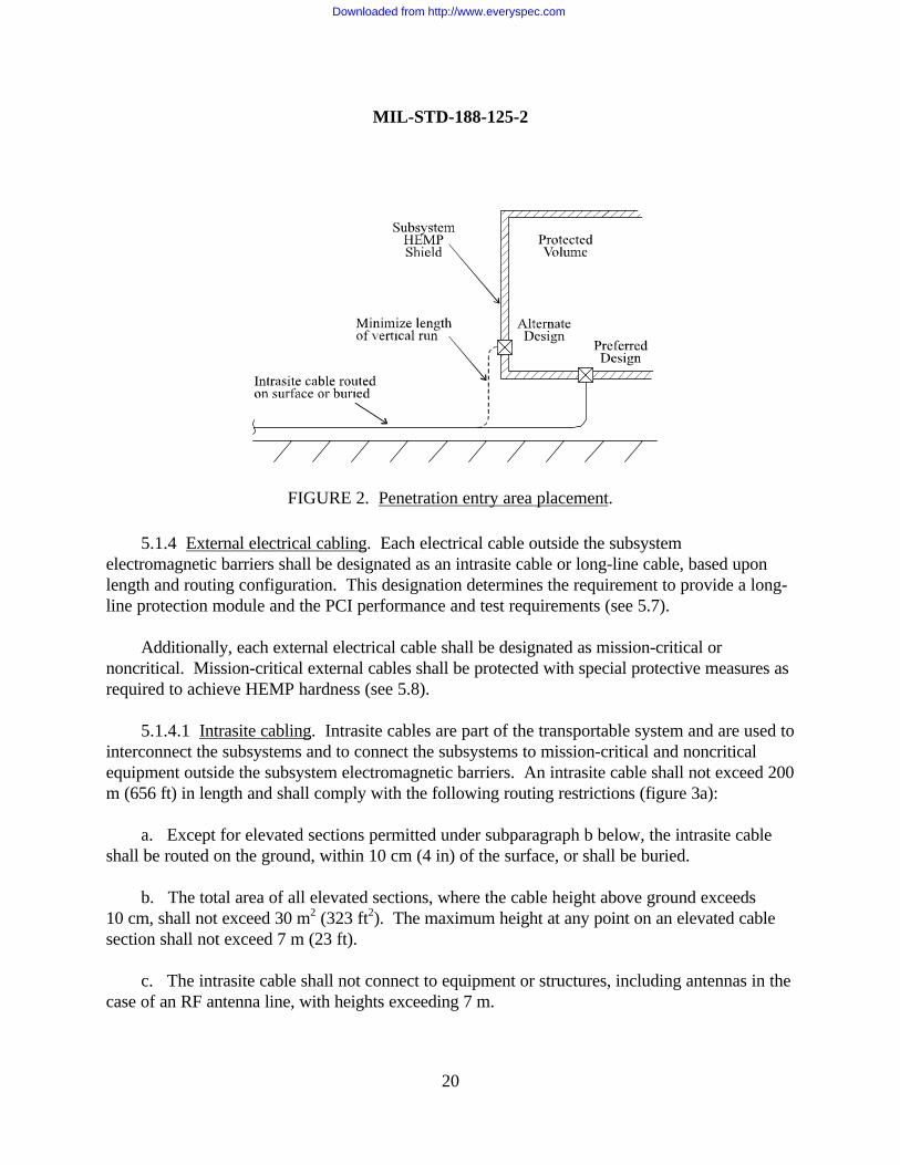
5.1.3 Penetration entry area. As a design objective, there should be a single penetrationentry area on the electromagnetic barrier of each HEMP-protected subsystem for all piping andelectrical (including fiber optic waveguide-below-cutoff) POEs, except roof-mounted antenna linePOEs. The penetration entry area shall be located as far as practical from normal and emergencypersonnel entries/exits, equipment accesses, and ventilation POEs. In addition, the penetrationentry area shall be located either on the floor shield surface of an elevated subsystem or as closeas practical to the ground on a wall shield surface to minimize the length of vertical cable run(figure 2). Radio frequency (RF) antenna line POEs for roof-mounted antennas shall penetratethe barrier as close as practical to the mounting point.
Downloaded from http://www.everyspec.com
MIL-STD-188-125-2
20
5.1.4 External electrical cabling. Each electrical cable outside the subsystemelectromagnetic barriers shall be designated as an intrasite cable or long-line cable, based uponlength and routing configuration. This designation determines the requirement to provide a long-line protection module and the PCI performance and test requirements (see 5.7).
Additionally, each external electrical cable shall be designated as mission-critical ornoncritical. Mission-critical external cables shall be protected with special protective measures asrequired to achieve HEMP hardness (see 5.8).
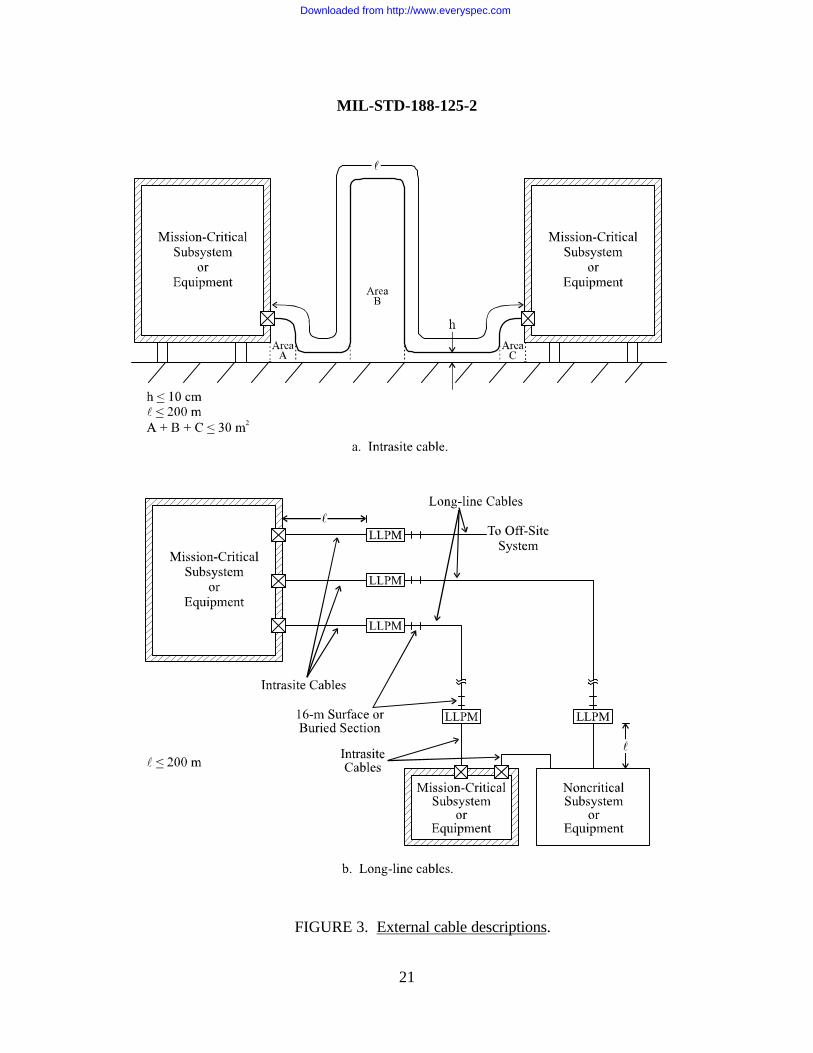
5.1.4.1 Intrasite cabling. Intrasite cables are part of the transportable system and are used tointerconnect the subsystems and to connect the subsystems to mission-critical and noncriticalequipment outside the subsystem electromagnetic barriers. An intrasite cable shall not exceed 200m (656 ft) in length and shall comply with the following routing restrictions (figure 3a):
a. Except for elevated sections permitted under subparagraph b below, the intrasite cableshall be routed on the ground, within 10 cm (4 in) of the surface, or shall be buried.
b. The total area of all elevated sections, where the cable height above ground exceeds10 cm, shall not exceed 30 m2 (323 ft2). The maximum height at any point on an elevated cablesection shall not exceed 7 m (23 ft).
c. The intrasite cable shall not connect to equipment or structures, including antennas in thecase of an RF antenna line, with heights exceeding 7 m.
FIGURE 2. Penetration entry area placement.
Downloaded from http://www.everyspec.com
MIL-STD-188-125-2
21
FIGURE 3. External cable descriptions.
Downloaded from http://www.everyspec.com
MIL-STD-188-125-2
22
The length and routing restrictions apply to a single intrasite cable, whether shielded orunshielded. In the case of an external cable that branches between the end points, the restrictionsapply to the sums of the lengths and areas on all branches.
5.1.4.2 Long-line cabling. Long-line cables include commercial power, telephone,communications, and other electrical conductors that extend beyond the transportable systemdeployment site. Segments of subsystem and equipment interconnecting cables that do notcomply with the length and routing restrictions for intrasite cables shall also be designated aslong-line cables (figure 3b). The number of long-line cables connected to the system shall beminimized. As a design objective, the system should be capable of performing the trans- and post-HEMP attack missions when disconnected from all long-line cables.
LLPMs shall be provided, except on long RF antenna lines, to isolate the intrasite cable plantand the mission-critical subsystems and equipment from transients that can be induced on thelong-lines by the HEMP threat environment (see 5.7.2). An LLPM may be connected to multiplelong-line cables or multiple intrasite cables, and several LLPMs may be combined into a singleassembly.
Commercial power lines, commercial telephone lines, and other long-line electricalconductors that extend beyond the deployment site shall be designed to be readily disconnectable.As a design objective, long-line segments of interconnecting cables should also be designed to bedisconnectable. The ability to disconnect a long-line shall not be used as a substitute for theLLPM requirement.
5.2 Transportable system grounding.
5.2.1 Equipotential ground plane. Each subsystem shield shall be grounded by theequipotential ground plane method IAW guidance in MIL-HDBK-419. The subsystem HEMPshields shall be employed as the equipotential ground planes.
5.2.2 Grounding to the subsystem HEMP shields. Grounds for equipment and structuresenclosed within protected volumes shall be electrically bonded to the inside surface of a shield bythe shortest practical path. Grounds for equipment and structures outside the electromagneticbarriers shall be electrically bonded to the outside surface of a shield or to the earth electrodesubsystem. Ground cables used to connect subsystem shields (equipotential ground planes) to theearth electrode subsystem shall be electrically bonded to the outside surface of a shield, and atleast one such ground cable shall be located at each penetration entry area. All groundingconnections to the subsystem HEMP shields shall be made in a manner that does not create POEs.
Downloaded from http://www.everyspec.com
MIL-STD-188-125-2
23
5.2.3 Long-line protection module grounding. Grounding shall be provided at each LLPM.The LLPM ground shall be sufficient for proper operation of the protection module.
5.3 Subsystem HEMP shields.
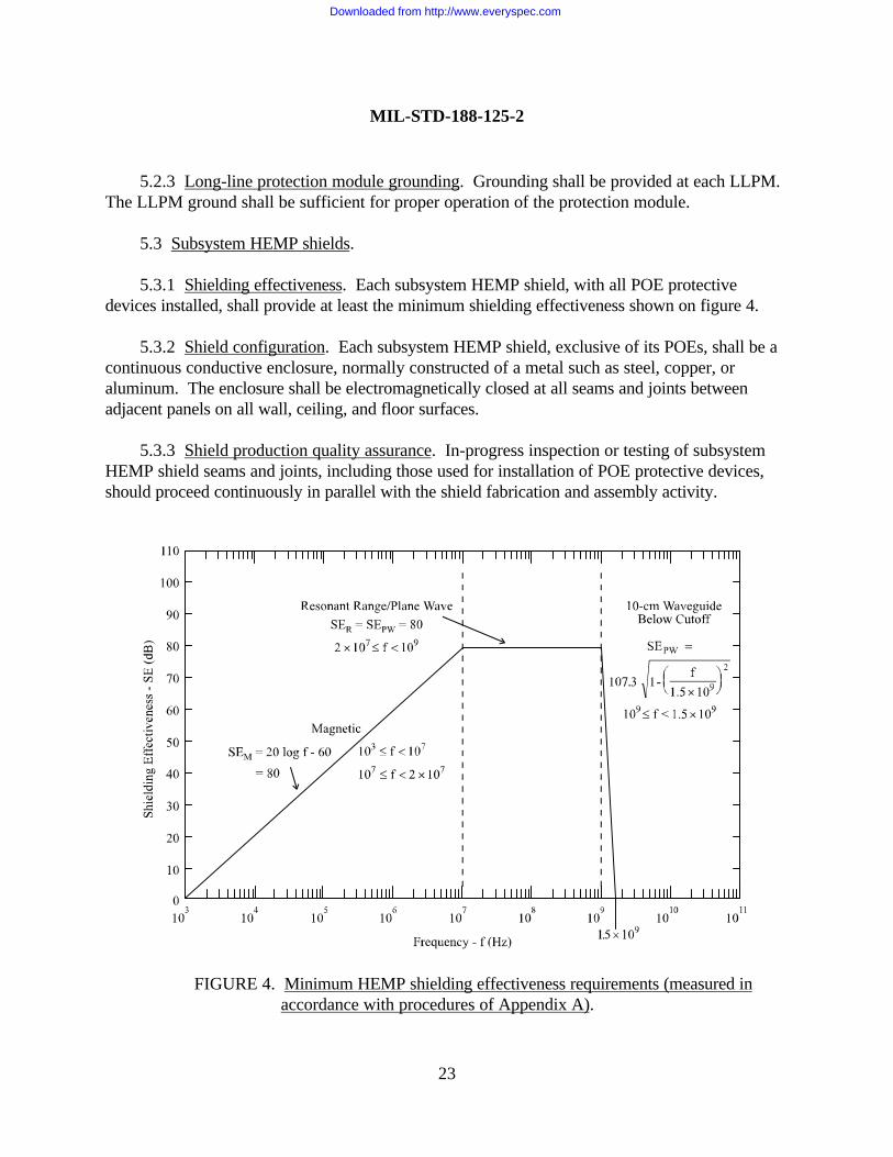
5.3.1 Shielding effectiveness. Each subsystem HEMP shield, with all POE protectivedevices installed, shall provide at least the minimum shielding effectiveness shown on figure 4.
5.3.2 Shield configuration. Each subsystem HEMP shield, exclusive of its POEs, shall be acontinuous conductive enclosure, normally constructed of a metal such as steel, copper, oraluminum. The enclosure shall be electromagnetically closed at all seams and joints betweenadjacent panels on all wall, ceiling, and floor surfaces.
5.3.3 Shield production quality assurance. In-progress inspection or testing of subsystemHEMP shield seams and joints, including those used for installation of POE protective devices,should proceed continuously in parallel with the shield fabrication and assembly activity.
FIGURE 4. Minimum HEMP shielding effectiveness requirements (measured in accordance with procedures of Appendix A).
Downloaded from http://www.everyspec.com
MIL-STD-188-125-2
24
5.3.4 Shield acceptance testing. After completion of each subsystem HEMP shield andinstallation of the POE protective devices, but before installation of MCE, the shield acceptancetest shall be conducted to determine if the shield performs IAW minimum requirements shown onfigure 4. The test shall be conducted using shielding effectiveness test procedures of Appendix A.All defects found during the acceptance testing shall be corrected, retested, and shown to providethe required performance.
5.3.4.1 Subsystem shield modifications. If POEs are added or the subsystem HEMP shieldis breached and repaired after acceptance testing, shield acceptance testing in the affected areashall be repeated.
5.4 Architectural POEs.
5.4.1 HEMP protection for architectural POEs. Architectural POEs include personnelentryways and exits and equipment access doors and panels through a subsystem HEMP shield.HEMP protection for all architectural POEs shall be provided with electromagnetic closuretechniques, such as shielded doors and welded or RF gasketed metal access covers.
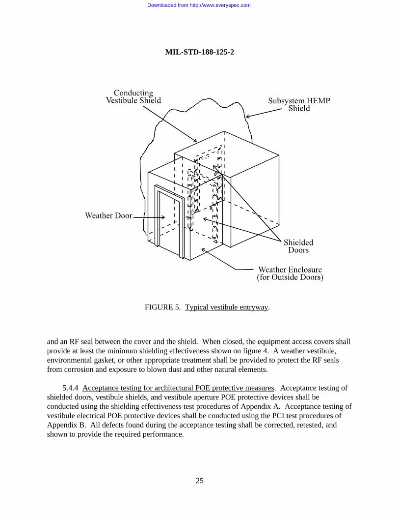
5.4.2 Personnel entryways and exits. HEMP protection for personnel entryways and exitsshall be provided with shielded doors or with two-door shielded vestibules (figure 5). Wiring inthe protected volumes (equipment side of a single door or inner vestibule door) shall be routed asfar as practical from the door seals.
5.4.2.1 Shielded doors. When installed and closed, shielded doors shall provide at least theminimum shielding effectiveness shown on figure 4. A weather enclosure, environmental gasket,or other appropriate treatment shall be provided on exterior doors to protect the RF seals fromcorrosion and exposure to blown dust and other natural elements.
5.4.2.2 Shielded vestibules. When a shielded vestibule is used to achieve more reliableperformance, the vestibule shield shall comply with the same requirements that apply to thesubsystem HEMP shields. All vestibule POE protective devices, either into the subsystemprotected volume or to the outside, shall comply with the same requirements that apply to otherPOE protective devices through the electromagnetic barrier (see 5.5. through 5.7). As designobjectives, vestibule shielded doors should be at 90 degrees to each other and they should beprovided with interlocks or alarms to ensure that at least one of the doors remains closed at alltimes except during emergency evacuations.
5.4.3 Equipment accesses. Separate equipment access POEs through the subsystem HEMPshields shall be provided only when movement of the equipment through a personnel entryway isnot practical. HEMP protection for equipment access POEs shall be provided with a metal cover
Downloaded from http://www.everyspec.com
MIL-STD-188-125-2
25
and an RF seal between the cover and the shield. When closed, the equipment access covers shallprovide at least the minimum shielding effectiveness shown on figure 4. A weather vestibule,environmental gasket, or other appropriate treatment shall be provided to protect the RF sealsfrom corrosion and exposure to blown dust and other natural elements.
5.4.4 Acceptance testing for architectural POE protective measures. Acceptance testing ofshielded doors, vestibule shields, and vestibule aperture POE protective devices shall beconducted using the shielding effectiveness test procedures of Appendix A. Acceptance testing ofvestibule electrical POE protective devices shall be conducted using the PCI test procedures ofAppendix B. All defects found during the acceptance testing shall be corrected, retested, andshown to provide the required performance.
FIGURE 5. Typical vestibule entryway.
Downloaded from http://www.everyspec.com
MIL-STD-188-125-2
26
5.5 Mechanical POEs.
5.5.1 HEMP protection for mechanical POEs. HEMP protection for mechanical POEs,including piping and ventilation penetrations through a subsystem HEMP shield, shall be providedwith waveguide-below-cutoff techniques. As design objectives, the number of piping POEsshould be constrained to no more than five per HEMP-protected subsystem and the number ofventilation POEs should be limited to no more than three per HEMP-protected subsystem.
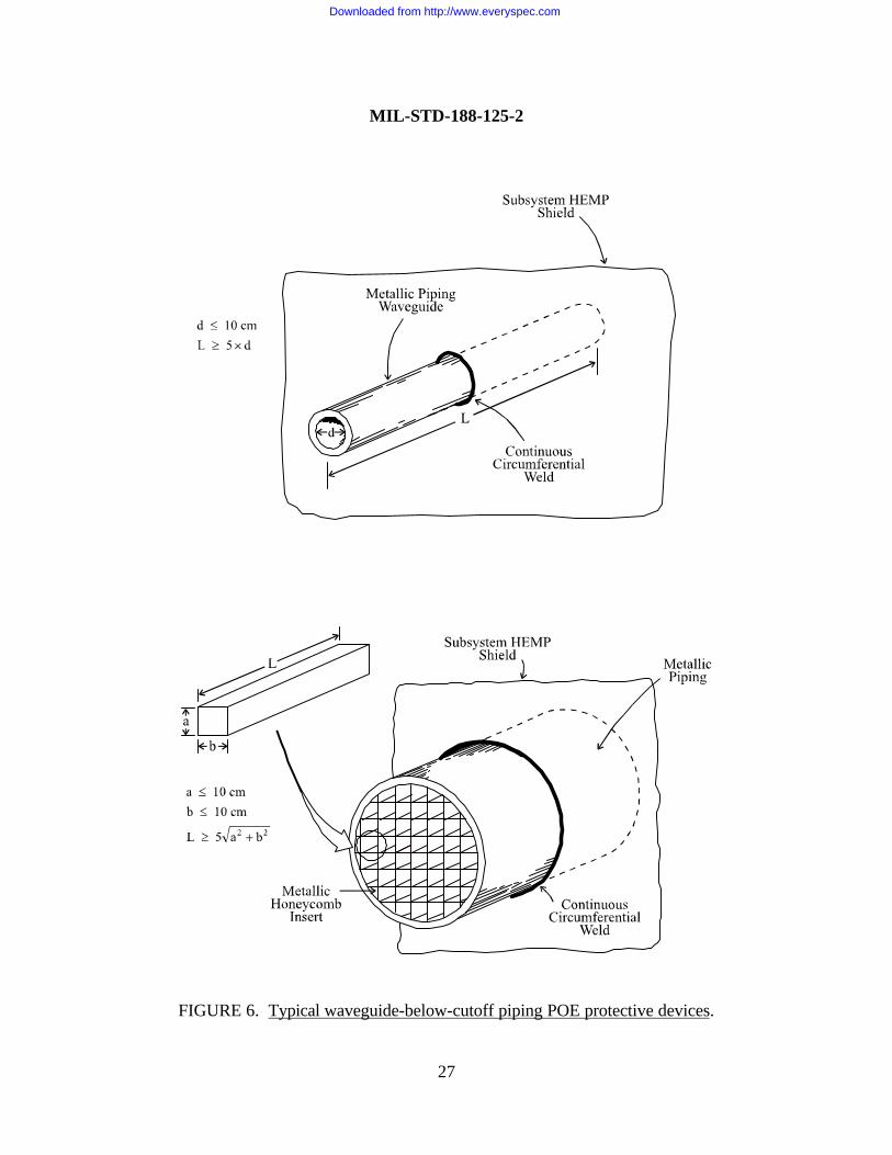
5.5.2 Piping POEs. Piping shall penetrate a subsystem HEMP shield as metallic pipesections that are configured as single waveguides below cutoff or WBC arrays (figure 6).Dielectric hoses or pipes shall be converted to metal piping before penetrating a subsystem HEMPshield. The presence of the protected piping POEs shall not degrade the shielding effectiveness ofthe subsystem HEMP shield below the minimum requirements shown onfigure 4.
The inside diameter of a single piping POE WBC and the transverse cell dimensions of eachof the cells in a piping POE WBC array shall be limited such that the cutoff frequency is at least1.5 GHz. The length of the waveguide section shall be sufficient to provide at least 80 dB ofattenuation at 1 GHz. No dielectric (glass, plastic, etc.) pipe lining shall be permitted in thewaveguide section. External and internal piping shall be connected at ends of the waveguidesection; no HEMP-unique requirements apply to these couplings. If a piping POE protectiondevice cannot be designed to satisfy these restrictions without interfering with the fluid flowrequirements, a special protective volume shall be established (see 5.8.3.1).
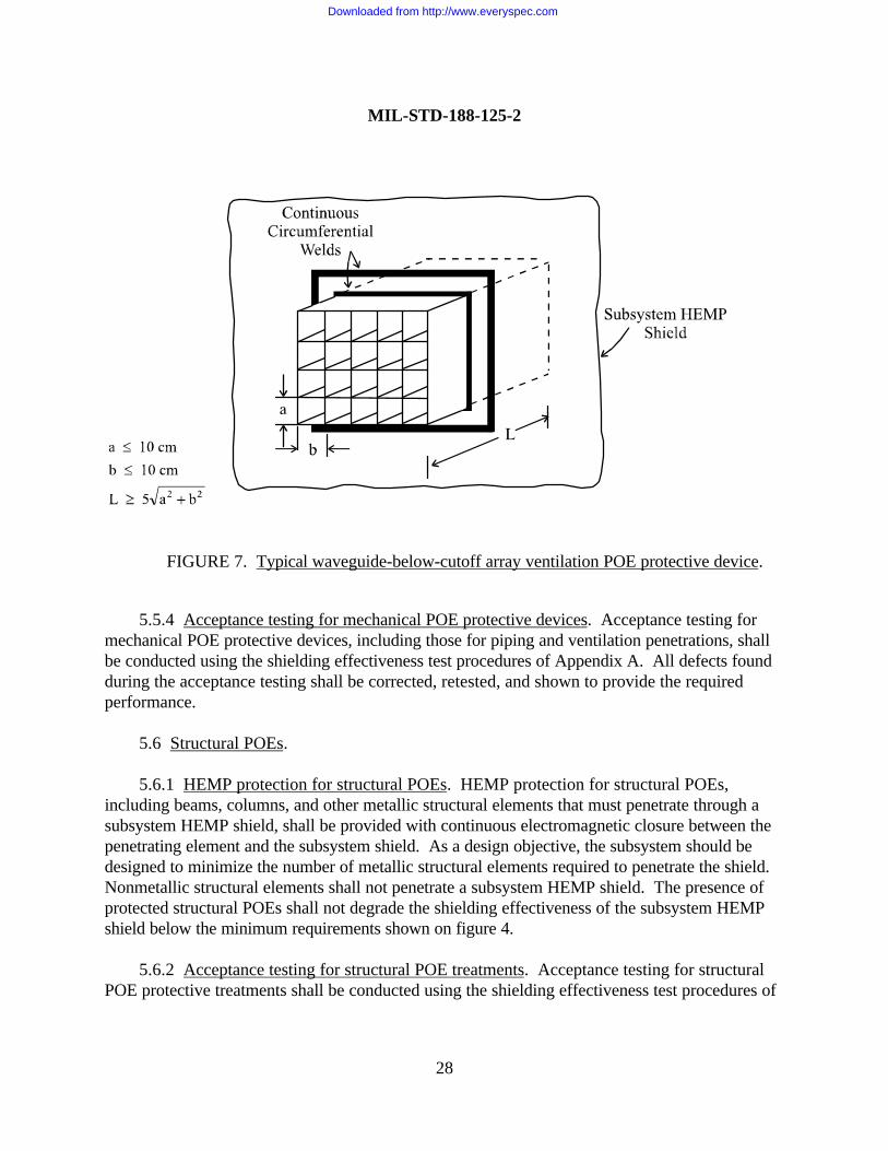
5.5.3 Ventilation POEs. Ventilation ducts shall penetrate a subsystem HEMP shield assections of metallic ducting that are configured as waveguide-below-cutoff arrays (figure 7). Thepresence of the protected ventilation POEs shall not degrade the shielding effectiveness of thesubsystem HEMP shield below the minimum requirements shown on figure 4.
The transverse cell dimensions of each of the cells in a ventilation POE WBC array shall belimited such that the cutoff frequency is at least 1.5 GHz. The length of the waveguide sectionshall be sufficient to provide at least 80 dB of attenuation at 1 GHz. No conductors shall bepermitted to penetrate through the waveguide cells.
Downloaded from http://www.everyspec.com
MIL-STD-188-125-2
27
FIGURE 6. Typical waveguide-below-cutoff piping POE protective devices.
Downloaded from http://www.everyspec.com
MIL-STD-188-125-2
28
5.5.4 Acceptance testing for mechanical POE protective devices. Acceptance testing formechanical POE protective devices, including those for piping and ventilation penetrations, shallbe conducted using the shielding effectiveness test procedures of Appendix A. All defects foundduring the acceptance testing shall be corrected, retested, and shown to provide the requiredperformance.
5.6 Structural POEs.
5.6.1 HEMP protection for structural POEs. HEMP protection for structural POEs,including beams, columns, and other metallic structural elements that must penetrate through asubsystem HEMP shield, shall be provided with continuous electromagnetic closure between thepenetrating element and the subsystem shield. As a design objective, the subsystem should bedesigned to minimize the number of metallic structural elements required to penetrate the shield.Nonmetallic structural elements shall not penetrate a subsystem HEMP shield. The presence ofprotected structural POEs shall not degrade the shielding effectiveness of the subsystem HEMPshield below the minimum requirements shown on figure 4.
5.6.2 Acceptance testing for structural POE treatments. Acceptance testing for structuralPOE protective treatments shall be conducted using the shielding effectiveness test procedures of
FIGURE 7. Typical waveguide-below-cutoff array ventilation POE protective device.
Downloaded from http://www.everyspec.com
MIL-STD-188-125-2
29
Appendix A. All defects found during the acceptance testing shall be corrected, retested, andshown to provide the required performance.
5.7 Electrical POEs and long-line protection modules.
5.7.1 Electrical POEs.
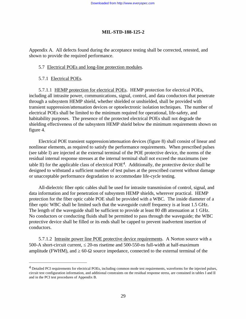
5.7.1.1 HEMP protection for electrical POEs. HEMP protection for electrical POEs,including all intrasite power, communications, signal, control, and data conductors that penetratethrough a subsystem HEMP shield, whether shielded or unshielded, shall be provided withtransient suppression/attenuation devices or optoelectronic isolation techniques. The number ofelectrical POEs shall be limited to the minimum required for operational, life-safety, andhabitability purposes. The presence of the protected electrical POEs shall not degrade theshielding effectiveness of the subsystem HEMP shield below the minimum requirements shown onfigure 4.
Electrical POE transient suppression/attenuation devices (figure 8) shall consist of linear andnonlinear elements, as required to satisfy the performance requirements. When prescribed pulses(see table I) are injected at the external terminal of the POE protective device, the norms of theresidual internal response stresses at the internal terminal shall not exceed the maximums (seetable II) for the applicable class of electrical POE4. Additionally, the protective device shall bedesigned to withstand a sufficient number of test pulses at the prescribed current without damageor unacceptable performance degradation to accommodate life-cycle testing.
All-dielectric fiber optic cables shall be used for intrasite transmission of control, signal, anddata information and for penetration of subsystem HEMP shields, wherever practical. HEMPprotection for the fiber optic cable POE shall be provided with a WBC. The inside diameter of afiber optic WBC shall be limited such that the waveguide cutoff frequency is at least 1.5 GHz.The length of the waveguide shall be sufficient to provide at least 80 dB attenuation at 1 GHz.No conductors or conducting fluids shall be permitted to pass through the waveguide; the WBCprotective device shall be filled or its ends shall be capped to prevent inadvertent insertion ofconductors.
5.7.1.2 Intrasite power line POE protective device requirements. A Norton source with a500-A short-circuit current, ≤ 20-ns risetime and 500-550-ns full-width at half-maximumamplitude (FWHM), and ≥ 60-Ω source impedance, connected to the external terminal of the
4 Detailed PCI requirements for electrical POEs, including common mode test requirements, waveforms for the injected pulses,circuit test configuration information, and additional constraints on the residual response stress, are contained in tables I and IIand in the PCI test procedures of Appendix B.
Downloaded from http://www.everyspec.com
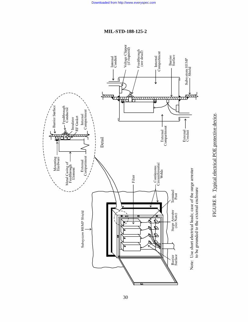
FIG
UR
E 8.
Typ
ical
ele
ctric
al P
OE
prot
ectiv
e de
vice
.
MIL-STD-188-125-2
30
Downloaded from http://www.everyspec.com
TAB
LE I.
Nor
ton
sour
ce p
aram
eter
s, w
avef
orm
s, a
nd a
ccep
tanc
e te
st lo
ads
for e
lect
rical
PO
E in
ject
ion
spec
ifica
tions
.
a. E
lect
rical
PO
Es, e
xcep
t RF
ante
nna
line
POEs
.
Cla
ss o
f Ele
ctric
al P
OE/
Type
of I
njec
tion1
Peak
Sho
rt-C
ircui
t Cur
rent
(A
)
Sour
ceIm
peda
nce
(ohm
s)R
iset
ime
(s)
FWH
M(s
)
Acc
epta
nce
Test
Res
ista
nce
(ohm
s)
Intra
site
pow
er li
ne P
OEs
Sh
ort p
ulse
com
mon
mod
e21,
000
≥ 60
≤ 2×
10-8
5×10
-7 -
5.5×
10-7
Not
app
licab
le
Sh
ort p
ulse
wire
-to-g
roun
d350
0≥
60≤
2×10
-85×
10-7
- 5.
5×10
-74 2
or V
rate
d/Ira
ted
In
term
edia
te p
ulse
com
mon
mod
e2,5
250
≥ 10
≤ 1.
5×10
-63×
10-3
- 5×1
0-3N
ot a
pplic
able
In
term
edia
te p
ulse
wire
-to-g
roun
d3,5
250
≥ 10
≤ 1.
5×10
-63×
10-3
- 5×1
0-350
Intra
site
con
trol/s
igna
l/dat
a lin
e PO
Es
Sh
ort p
ulse
com
mon
mod
e21,
000
≥ 60
≤ 2×
10-8
5×10
-7 -
5.5×
10-7
Not
app
licab
le
Sh
ort p
ulse
wire
-to-g
roun
d36 1
,000
/N
or
100
≥ 60
≤ 2×
10-8
5×10
-7 -
5.5×
10-7
4 2
or V
rate
d/Ira
ted
In
term
edia
te p
ulse
com
mon
mod
e2,5
250
≥ 10
≤ 1.
5×10
-63×
10-3
- 5×1
0-3N
ot a
pplic
able
In
term
edia
te p
ulse
wire
-to-
gr
ound
3,5,
725
0≥
10≤
1.5×
10-6
3×10
-3 - 5
×10-3
50
MIL-STD-188-125-2
31
Downloaded from http://www.everyspec.com
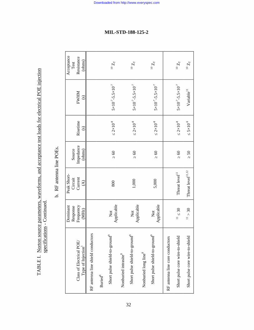
TAB
LE I.
Nor
ton
sour
ce p
aram
eter
s, w
avef
orm
s, a
nd a
ccep
tanc
e te
st lo
ads
for e
lect
rical
PO
E in
ject
ion
spe
cific
atio
ns -
Con
tinue
d.
b. R
F an
tenn
a lin
e PO
Es.
Cla
ss o
f Ele
ctric
al P
OE/
Type
of I
njec
tion1
Dom
inan
tR
espo
nse
Freq
uenc
y(M
Hz)
Peak
Sho
rt-C
ircui
tC
urre
nt (A
)
Sour
ceIm
peda
nce
(ohm
s)R
iset
ime
(s)
FWH
M(s
)
Acc
epta
nce
Test
Res
ista
nce
(ohm
s)
RF
ante
nna
line
shie
ld c
ondu
ctor
s
B
urie
d8
Shor
t pul
se s
hiel
d-to
-gro
und9
N
onbu
ried
intra
site
8
Shor
t pul
se s
hiel
d-to
-gro
und9
N
onbu
ried
long
line
8
Shor
t pul
se s
hiel
d-to
-gro
und9
Not
App
licab
le
Not
App
licab
le
Not
App
licab
le
800
1,00
0
5,00
0
≥ 60
≥ 60
≥ 60
≤ 2×
10-8
≤ 2×
10-8
≤ 2×
10-8
5×10
-7-5
.5×1
0-7
5×10
-7-5
.5×1
0-7
5×10
-7-5
.5×1
0-7
10 Z
T
10 Z
T
10 Z
T
RF
ante
nna
line
core
con
duct
ors
Sh
ort p
ulse
cor
e w
ire-to
-shi
eld
11 ≤
30
Thre
at le
vel11
≥ 60
≤ 2×
10-8
5×10
-7-5
.5×1
0-710
ZT
Sh
ort p
ulse
cor
e w
ire-to
-shi
eld
11 >
30
Thre
at le
vel11
,12
≥ 50
≤ 5×
10-9
Var
iabl
e1110
ZT
32
MIL-STD-188-125-2
Downloaded from http://www.everyspec.com
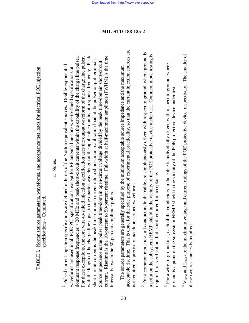
TAB
LE I.
Nor
ton
sour
ce p
aram
eter
s, w
avef
orm
s, a
nd a
ccep
tanc
e te
st lo
ads
for e
lect
rical
PO
E in
ject
ion
spe
cific
atio
ns -
Con
tinue
d.
c. N
otes
.
1 Pul
sed
curr
ent i
njec
tion
spec
ifica
tions
are
def
ined
in te
rms
of th
e N
orto
n eq
uiva
lent
sou
rces
. D
oubl
e-ex
pone
ntia
lw
avef
orm
s ar
e us
ed in
all
POE
PCI s
peci
ficat
ions
, exc
ept f
or R
F an
tenn
a lin
e co
re w
ire-to
-shi
eld
spec
ifica
tions
at
dom
inan
t res
pons
e fr
eque
ncie
s >
30 M
Hz
and
peak
sho
rt-ci
rcui
t cur
rent
s w
ithin
the
capa
bilit
y of
the
char
ge li
ne p
ulse
r.Fo
r the
se e
xcep
tions
, the
cor
e w
ire-to
-shi
eld
inje
ctio
n sp
ecifi
catio
n us
es th
e ou
tput
wav
efor
m o
f the
cha
rge
line
puls
er,
with
the
leng
th o
f the
cha
rge
line
equa
l to
the
quar
ter-
wav
elen
gth
at th
e ap
plic
able
dom
inan
t res
pons
e fr
eque
ncy.
Pea
ksh
ort-c
ircui
t cur
rent
is th
e pe
ak ti
me-
dom
ain
curr
ent i
nto
a sh
ort-c
ircui
t cal
ibra
tion
load
at t
he p
ulse
r out
put t
erm
inal
s.So
urce
impe
danc
e is
the
puls
er p
eak
time-
dom
ain
open
-circ
uit v
olta
ge d
ivid
ed b
y th
e pe
ak ti
me-
dom
ain
shor
t-circ
uit
curr
ent.
Ris
etim
e is
the
10-p
erce
nt to
90-
perc
ent r
iset
ime.
Ful
l-wid
th a
t hal
f-m
axim
um a
mpl
itude
(FW
HM
) is
the
time
inte
rval
bet
wee
n th
e 50
-per
cent
am
plitu
de p
oint
s.
The
sour
ce p
aram
eter
s ar
e ge
nera
lly s
peci
fied
by th
e m
inim
um a
ccep
tabl
e so
urce
impe
danc
e an
d th
e m
axim
umac
cept
able
rise
time.
Thi
s is
don
e fo
r the
sol
e pu
rpos
e of
exp
erim
enta
l pra
ctic
ality
, so
that
the
curr
ent i
njec
tion
sour
ces
are
not r
equi
red
to p
reci
sely
mat
ch p
resc
ribed
wav
efor
ms.
2 For
a c
omm
on m
ode
test
, all
cond
ucto
rs in
the
cabl
e ar
e si
mul
tane
ousl
y dr
iven
with
resp
ect t
o gr
ound
, whe
re g
roun
d is
a po
int o
n th
e su
bsys
tem
HEM
P sh
ield
in th
e vi
cini
ty o
f the
PO
E pr
otec
tive
devi
ce u
nder
test
. C
omm
on m
ode
test
ing
isre
quire
d fo
r ver
ifica
tion,
but
is n
ot re
quire
d fo
r acc
epta
nce.
3 For
a w
ire-to
-gro
und
test
, eac
h of
the
cond
ucto
rs in
the
cabl
e is
indi
vidu
ally
driv
en w
ith re
spec
t to
grou
nd, w
here
grou
nd is
a p
oint
on
the
subs
yste
m H
EMP
shie
ld in
the
vici
nity
of t
he P
OE
prot
ectiv
e de
vice
und
er te
st.
4 Vra
ted a
nd I r
ated
are
the
max
imum
vol
tage
and
cur
rent
ratin
gs o
f the
PO
E pr
otec
tive
devi
ce, r
espe
ctiv
ely.
The
sm
alle
r of
thes
e tw
o re
sist
ance
s is
requ
ired.
33
MIL-STD-188-125-2
Downloaded from http://www.everyspec.com
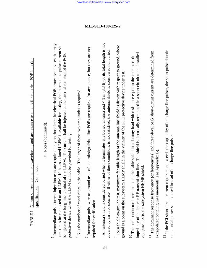
TAB
LE I.
Nor
ton
sour
ce p
aram
eter
s, w
avef
orm
s, a
nd a
ccep
tanc
e te
st lo
ads
for e
lect
rical
PO
E in
ject
ion
spec
ifica
tions
- C
ontin
ued.
c. N
otes
(con
tinue
d).
5 Inte
rmed
iate
pul
se c
urre
nt in
ject
ion
test
s ar
e re
quire
d on
ly o
n th
ose
intra
site
ele
ctric
al P
OE
prot
ectiv
e de
vice
s th
at m
ayso
met
imes
be
conn
ecte
d to
an
LLPM
. If
the
asso
ciat
ed L
LPM
is a
vaila
ble
for t
estin
g, th
e in
term
edia
te p
ulse
cur
rent
sha
llbe
inje
cted
at t
he lo
ng-li
ne te
rmin
al o
f the
LLP
M.
The
curr
ent s
hall
be in
ject
ed a
t the
ext
erna
l ter
min
al o
f the
PO
Epr
otec
tive
devi
ce w
hen
the
LLPM
can
not b
e pr
ovid
ed fo
r tes
ting.
6 N is
the
num
ber o
f con
duct
ors
in th
e ca
ble.
The
larg
er o
f the
se tw
o am
plitu
des
is re
quire
d.
7 Inte
rmed
iate
pul
se w
ire-to
-gro
und
test
s of
con
trol/s
igna
l/dat
a lin
e PO
Es a
re re
quire
d fo
r acc
epta
nce,
but
they
are
not
requ
ired
for v
erifi
catio
n.
8 An
ante
nna
shie
ld is
con
side
red
burie
d w
hen
it te
rmin
ates
at a
bur
ied
ante
nna
and
< 1
m (3
.3 ft
) of i
ts to
tal l
engt
h is
not
cove
red
by e
arth
or c
oncr
ete.
If e
ither
of t
hese
con
ditio
ns is
not
sat
isfie
d, th
e an
tenn
a sh
ield
is c
onsi
dere
d no
nbur
ied.
9 For
a s
hiel
d-to
-gro
und
test
, max
imum
feas
ible
leng
th o
f the
ant
enna
line
shi
eld
is d
riven
with
resp
ect t
o gr
ound
, whe
regr
ound
is a
poi
nt o
n th
e su
bsys
tem
HEM
P sh
ield
in th
e vi
cini
ty o
f the
PO
E pr
otec
tive
devi
ce u
nder
test
.
10 T
he c
ore
cond
ucto
r is
term
inat
ed to
the
cabl
e sh
ield
in a
dum
my
load
with
resi
stan
ce e
qual
to th
e ch
arac
teris
ticim
peda
nce
of th
e in
terio
r RF
trans
mis
sion
line
. Th
e sh
ield
is e
lect
rical
ly te
rmin
ated
in a
sho
rt ci
rcui
t to
the
inst
alle
deq
uipm
ent o
r to
the
subs
yste
m H
EMP
shie
ld.
11 T
he d
omin
ant r
espo
nse
freq
uenc
y (o
r fre
quen
cies
) and
thre
at-le
vel p
eak
shor
t-circ
uit c
urre
nt a
re d
eter
min
ed fr
omex
trapo
late
d co
uplin
g m
easu
rem
ents
(see
App
endi
x B
).
12 If
the
PCI s
hort-
circ
uit c
urre
nt re
quire
men
t exc
eeds
the
capa
bilit
y of
the
char
ge li
ne p
ulse
r, th
e sh
ort p
ulse
dou
ble-
expo
nent
ial p
ulse
r sha
ll be
use
d in
stea
d of
the
char
ge li
ne p
ulse
r.
MIL-STD-188-125-2
34
Downloaded from http://www.everyspec.com
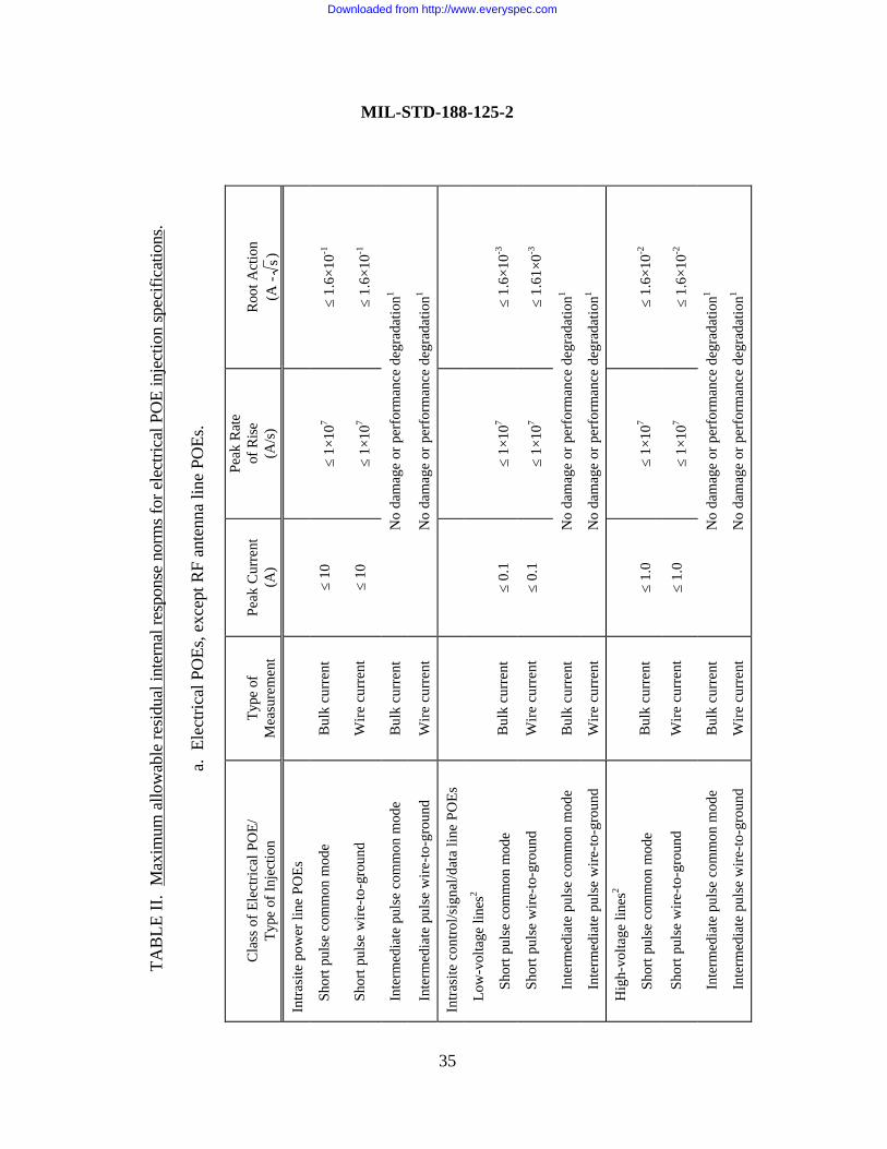
TAB
LE II
. M
axim
um a
llow
able
resi
dual
inte
rnal
resp
onse
nor
ms
for e
lect
rical
PO
E in
ject
ion
spec
ifica
tions
.
a. E
lect
rical
PO
Es, e
xcep
t RF
ante
nna
line
POEs
.
Cla
ss o
f Ele
ctric
al P
OE/
Type
of I
njec
tion
Type
of
Mea
sure
men
tPe
ak C
urre
nt(A
)
Peak
Rat
eof
Ris
e(A
/s)
Roo
t Act
ion
(A -
s)
Intra
site
pow
er li
ne P
OEs
Sh
ort p
ulse
com
mon
mod
eB
ulk
curr
ent
≤ 10
≤ 1×
107
≤ 1.
6×10
-1
Sh
ort p
ulse
wire
-to-g
roun
dW
ire c
urre
nt≤
10≤
1×10
7≤
1.6×
10-1
In
term
edia
te p
ulse
com
mon
mod
eB
ulk
curr
ent
No
dam
age
or p
erfo
rman
ce d
egra
datio
n1
In
term
edia
te p
ulse
wire
-to-g
roun
dW
ire c
urre
ntN
o da
mag
e or
per
form
ance
deg
rada
tion1
Intra
site
con
trol/s
igna
l/dat
a lin
e PO
Es
Lo
w-v
olta
ge li
nes2
Shor
t pul
se c
omm
on m
ode
Bul
k cu
rren
t≤
0.1
≤ 1×
107
≤ 1.
6×10
-3
Shor
t pul
se w
ire-to
-gro
und
Wire
cur
rent
≤ 0.
1≤
1×10
7≤
1.61
×0-3
Inte
rmed
iate
pul
se c
omm
on m
ode
Bul
k cu
rren
tN
o da
mag
e or
per
form
ance
deg
rada
tion1
Inte
rmed
iate
pul
se w
ire-to
-gro
und
Wire
cur
rent
No
dam
age
or p
erfo
rman
ce d
egra
datio
n1
H
igh-
volta
ge li
nes2
Shor
t pul
se c
omm
on m
ode
Bul
k cu
rren
t≤
1.0
≤ 1×
107
≤ 1.
6×10
-2
Shor
t pul
se w
ire-to
-gro
und
Wire
cur
rent
≤ 1.
0≤
1×10
7≤
1.6×
10-2
Inte
rmed
iate
pul
se c
omm
on m
ode
Bul
k cu
rren
tN
o da
mag
e or
per
form
ance
deg
rada
tion1
Inte
rmed
iate
pul
se w
ire-to
-gro
und
Wire
cur
rent
No
dam
age
or p
erfo
rman
ce d
egra
datio
n1
MIL-STD-188-125-2
35
Downloaded from http://www.everyspec.com
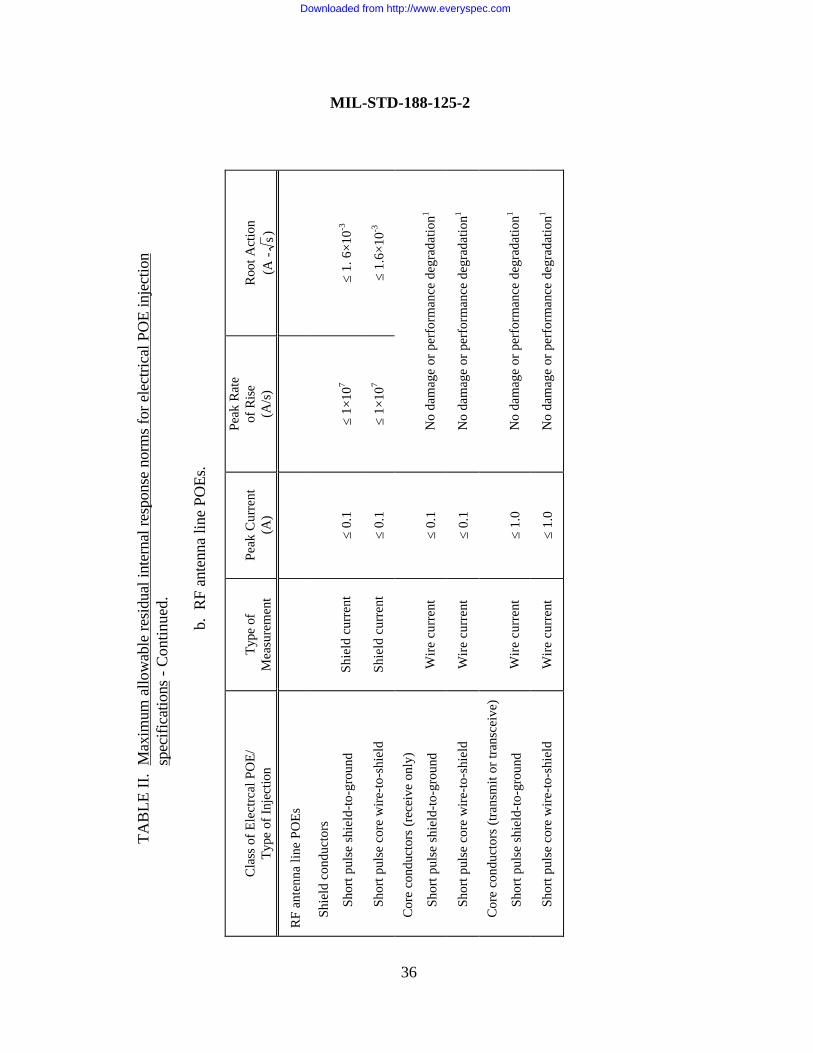
TAB
LE II
. M
axim
um a
llow
able
resi
dual
inte
rnal
resp
onse
nor
ms
for e
lect
rical
PO
E in
ject
ion
spec
ifica
tions
- C
ontin
ued.
b. R
F an
tenn
a lin
e PO
Es.
Cla
ss o
f Ele
ctrc
al P
OE/
Type
of I
njec
tion
Type
of
Mea
sure
men
tPe
ak C
urre
nt(A
)
Peak
Rat
eof
Ris
e(A
/s)
Roo
t Act
ion
(A -
s)
RF
ante
nna
line
POEs
Sh
ield
con
duct
ors
Shor
t pul
se s
hiel
d-to
-gro
und
Shie
ld c
urre
nt≤
0.1
≤ 1×
107
≤ 1.
6×1
0-3
Shor
t pul
se c
ore
wire
-to-s
hiel
dSh
ield
cur
rent
≤ 0.
1≤
1×10
7≤
1.6×
10-3
C
ore
cond
ucto
rs (r
ecei
ve o
nly)
Shor
t pul
se s
hiel
d-to
-gro
und
Wire
cur
rent
≤ 0.
1N
o da
mag
e or
per
form
ance
deg
rada
tion1
Shor
t pul
se c
ore
wire
-to-s
hiel
dW
ire c
urre
nt≤
0.1
No
dam
age
or p
erfo
rman
ce d
egra
datio
n1
C
ore
cond
ucto
rs (t
rans
mit
or tr
ansc
eive
)
Shor
t pul
se s
hiel
d-to
-gro
und
Wire
cur
rent
≤ 1.
0N
o da
mag
e or
per
form
ance
deg
rada
tion1
Shor
t pul
se c
ore
wire
-to-s
hiel
dW
ire c
urre
nt≤
1.0
No
dam
age
or p
erfo
rman
ce d
egra
datio
n1
MIL-STD-188-125-2
36
Downloaded from http://www.everyspec.com
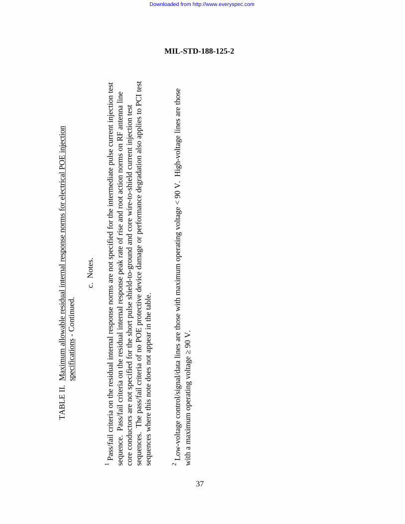
TAB
LE II
. M
axim
um a
llow
able
resi
dual
inte
rnal
resp
onse
nor
ms
for e
lect
rical
PO
E in
ject
ion
spec
ifica
tions
- C
ontin
ued.
c. N
otes
.
1 Pas
s/fa
il cr
iteria
on
the
resi
dual
inte
rnal
resp
onse
nor
ms
are
not s
peci
fied
for t
he in
term
edia
te p
ulse
cur
rent
inje
ctio
n te
stse
quen
ce.
Pass
/fail
crite
ria o
n th
e re
sidu
al in
tern
al re
spon
se p
eak
rate
of r
ise
and
root
act
ion
norm
s on
RF
ante
nna
line
core
con
duct
ors
are
not s
peci
fied
for t
he s
hort
puls
e sh
ield
-to-g
roun
d an
d co
re w
ire-to
-shi
eld
curr
ent i
njec
tion
test
sequ
ence
s. T
he p
ass/
fail
crite
ria o
f no
POE
prot
ectiv
e de
vice
dam
age
or p
erfo
rman
ce d
egra
datio
n al
so a
pplie
s to
PC
I tes
tse
quen
ces
whe
re th
is n
ote
does
not
app
ear i
n th
e ta
ble.
2 Low
-vol
tage
con
trol/s
igna
l/dat
a lin
es a
re th
ose
with
max
imum
ope
ratin
g vo
ltage
< 9
0 V
. H
igh-
volta
ge li
nes
are
thos
ew
ith a
max
imum
ope
ratin
g vo
ltage
≥ 9
0 V
.
MIL-STD-188-125-2
37
Downloaded from http://www.everyspec.com
MIL-STD-188-125-2
38
POE protective device on a penetrating power line conductor, shall produce a residual internalresponse stress no greater than 10 A and shall not cause device damage or performancedegradation4.
A Norton source with a 250-A short-circuit current, ≤ 1.5-µs risetime and 3-5-ms FWHM,and ≥ 10-Ω source impedance, connected to a penetrating power line conductor that maysometimes interface to an LLPM, shall not cause device damage or performance degradation4. Ifthe associated LLPM is available for testing, the intermediate pulse current shall be injected at thelong-line terminal of the LLPM. Only the cable to the POE protective device under test shall beconnected at the LLPM intrasite terminals during the injection, even if the LLPM normallyconnects to more than one subsystem or equipment. The current shall be injected at the externalterminal of the POE protective device under test, if the LLPM cannot be provided for testing.
If a POE protective device cannot be designed to satisfy the residual internal stress limits orfunctional requirements without interfering with operational signals that it is required to pass, aspecial protective volume shall be established (see 5.8.3.2).
5.7.1.3 Intrasite control, signal, and data line POE protective device requirements. ANorton source with a 1,000/ N or 100-A short-circuit current (where N is the number ofconductors in the cable, and the larger amplitude is chosen), ≤ 20-ns risetime and 500-550-nsFWHM, and ≥ 60-Ω source impedance, connected to the external terminal of the POE protectivedevice on a penetrating low-voltage control/signal/data line conductor, shall produce a residualinternal response stress no greater than 0.1 A and shall not cause device damage or performancedegradation4. A Norton source with a 1,000/ N or 100-A short-circuit current (where N is thenumber of conductors in the cable, and the larger amplitude is chosen), ≤ 20-ns risetime and 500-550-ns FWHM, and ≥ 60-Ω source impedance, connected to the external terminal of the POEprotective device on a penetrating high-voltage control/signal/data line conductor, shall produce aresidual internal response stress no greater than 1.0 A and shall not cause device damage orperformance degradation4. Low-voltage control/signal/data lines are those with maximumoperating voltage < 90 V; high-voltage lines are those with a maximum operating voltage≥ 90 V.
A Norton source with a 250-A short-circuit current, ≤ 1.5-µs risetime and 3-5-ms FWHM,and ≥ 10-Ω source impedance, connected to a penetrating control/signal/data line conductor thatmay sometimes interface to an LLPM, shall not cause device damage or performancedegradation4. If the associated LLPM is available for testing, the intermediate pulse current shallbe injected at the long-line terminal of the LLPM. Only the cable to the POE protective deviceunder test shall be connected at the LLPM intrasite terminals during the injection, even if theLLPM normally connects to more than one subsystem or equipment. The current shall be injected
Downloaded from http://www.everyspec.com
MIL-STD-188-125-2
39
at the external terminal of the POE protective device under test, if the LLPM cannot be providedfor testing.
If a POE protective device cannot be designed to satisfy the residual internal stress limits orfunctional requirements without interfering with operational signals that it is required to pass, aspecial protective volume shall be established (see 5.8.3.2).
5.7.1.4 Antenna line POE protective device requirements.
5.7.1.4.1 Core conductor injection requirements for receive-only antenna line POEprotective devices. A pulse of the prescribed waveform and amplitude, occurring on the signal-carrying core conductor at the antenna terminals of a receive-only antenna subsystem, shallproduce residual internal response stresses no greater than 0.1 A on the core conductor and shieldand shall not cause POE protective device damage or performance degradation4. An antennaprotective device may be used in conjunction with the POE protective device to achieve therequired transient suppression/attenuation. The waveform and amplitude of the pulses to beapplied shall be determined by threat extrapolation of coupling measurements. Couplingmeasurements shall be acquired under electromagnetic field excitation provided by CWimmersion, threat-level illumination, or another threat-relatable method. Coupling and PCI testdetails are provided in Appendix B.
If the antenna subsystem HEMP protection cannot be designed to satisfy the residual internalstress limits or functional requirements without interfering with operational signals that it isrequired to pass, a special protective volume shall be established (see 5.8.3.2).
5.7.1.4.2 Core conductor injection requirements for transmit antenna line POE protectivedevices. A pulse of the prescribed waveform and amplitude, occurring on the signal-carrying coreconductor at the antenna terminals of a transmit or transceive antenna subsystem, shall produceresidual internal response stresses no greater than 1.0 A on the core conductor and no greaterthan 0.1 A on the shield and shall not cause POE protective device damage or performancedegradation4. An antenna protective device may be used in conjunction with the POE protectivedevice to achieve the required transient suppression/attenuation. The waveform and amplitude ofthe pulses to be applied shall be determined by threat extrapolation of coupling measurements.Coupling measurements shall be acquired under electromagnetic field excitation provided by CWimmersion, threat-level illumination, or another threat-relatable method. Coupling and PCI testdetails are provided in Appendix B.
If the antenna subsystem HEMP protection cannot be designed to satisfy the residual internalstress limits or functional requirements without interfering with operational signals that it isrequired to pass, a special protective volume shall be established (see 5.8.3.2).
Downloaded from http://www.everyspec.com

MIL-STD-188-125-2
40
5.7.1.4.3 Shield injection requirements for antenna line POE protective devices. A Nortonsource with a 800-A short-circuit current, ≤ 20-ns risetime and 500-550-ns FWHM, and ≥ 60-Ωsource impedance, connected to the shield of a buried antenna line at a point outside theelectromagnetic barrier, shall produce residual internal response stresses no greater than peakcurrents in table IIb on the core conductor and shield and shall not cause device damage orperformance degradation4. A Norton source with a 1,000-A short-circuit current, ≤ 20-nsrisetime and 500-550-ns FWHM, and ≥ 60-Ω source impedance, connected to the shield of anonburied intrasite antenna line (see 5.1.4.1) at a point outside the electromagnetic barrier, shallproduce residual internal response stresses no greater than peak currents in table IIb on the coreconductor and shield and shall not cause device damage or performance degradation4. A Nortonsource with a 5,000-A short-circuit current, ≤ 20-ns risetime and 500-550-ns FWHM, and ≥60-Ω source impedance, connected to the shield of a nonburied long antenna line (see 5.1.4.2) ata point outside the electromagnetic barrier, shall produce residual internal response stresses nogreater than peak currents in table IIb on the core conductor and shield and shall not cause devicedamage or performance degradation4. An antenna line is considered buried when it terminates ata buried antenna and < 1 m (3.3 ft) of its total length is not covered by earth or concrete. If eitherof these conditions is not satisfied, the antenna line is considered nonburied.
5.7.1.5 Acceptance testing of electrical POE protective devices. Acceptance testing ofelectrical POE protective devices shall be conducted using the PCI test procedures of AppendixB. Acceptance testing of fiber optic POE waveguides below cutoff shall be conducted usingshielding effectiveness test procedures of Appendix A. All defects found during the acceptancetesting shall be corrected, retested, and shown to provide the required performance.
5.7.2 Long-line protection modules. LLPMs shall be provided, except on long RF antennalines, to isolate the intrasite cable plant and the mission-critical subsystems and equipment fromtransients that can be induced on the long-lines by the HEMP threat environment. LLPMs arerequired under all of the following conditions:
a. Where a commercial electrical power cable, a commercial telephone cable, or anotherlong-line power, control, signal, or data electrical cable that extends beyond the transportablesystem deployment site interfaces to the intrasite cable plant, whether the associated intrasitecables connect to mission-critical or noncritical elements of the system.
b. Where a long-line segment of an interconnecting power, control, signal, or data cable(see 5.1.4.2) interfaces to the intrasite cable plant, when the associated intrasite cables connect toone or more mission-critical elements of the system.
c. Where a long-line segment of an interconnecting power, control, signal, or data cableinterfaces to the intrasite cable plant, when the associated intrasite cables connect to a noncritical
Downloaded from http://www.everyspec.com
MIL-STD-188-125-2
41
system element that is then interconnected to a mission-critical subsystem or equipment throughany intrasite cable path.
LLPMs are not required on RF antenna lines.
The section of a long-line immediately before the connection at an LLPM shall be routed onthe ground or shall be buried for a length of at least 16 m (52.5 ft).
5.7.2.1 General requirements for LLPMs. HEMP protection provided by LLPMs shallconsist of linear and nonlinear transient suppression/attenuation devices or dielectric isolationtechniques, as required to satisfy the performance requirements. When prescribed pulses (seetable III) are injected at the long-line terminal of an LLPM, the norms of the residual responsestresses at the intrasite cable terminal shall not exceed the maximums (see table IV) for theapplicable class of LLPM5. Additionally, the LLPM shall be designed to withstand a sufficientnumber of test pulses at the prescribed current without damage or unacceptable performancedegradation to accommodate life-cycle testing.
5.7.2.2 Power line LLPM requirements. A Norton source with a 2,500-A short-circuitcurrent, ≤ 20-ns risetime and 500-550-ns FWHM, and ≥ 60-Ω source impedance, connected tothe long-line terminal of a power line LLPM, shall produce a residual response stress at theintrasite cable terminal no greater than 250 A and shall not cause unacceptable LLPM damage orperformance degradation5.
A Norton source with a 250-A short-circuit current, ≤ 1.5-µs risetime and 3-5-ms FWHM,and ≥ 10-Ω source impedance, connected to the long-line terminal of a power line LLPM, shallnot cause unacceptable LLPM damage or performance degradation5.
A Norton source with a 1,000-A short-circuit current, ≤ 0.2-s risetime and 20-25-s FWHM,and ≥ 5-Ω source impedance, connected to the long-line terminal of a power line LLPM, shallproduce a residual response stress at the intrasite cable terminal no greater than 10 A and shall notcause unacceptable LLPM damage or performance degradation5.
5.7.2.3 Control, signal, and data line LLPM requirements. A Norton source with a 5,000/N or 500-A short-circuit current (where N is the number of conductors in the cable, and the
larger amplitude is chosen), ≤ 20-ns risetime and 500-550-ns FWHM, and ≥ 60-Ω sourceimpedance, connected to the long-line terminal of a control/signal/data line LLPM, shall producea residual response stress at the intrasite cable terminal no greater than 500/ N or 50 A 5 Detailed PCI requirements for LLPMs, including common mode test requirements, waveforms for the injected pulses, circuittest configuration information, and additional constraints on the residual response stress, are contained in tables III and IV andin the PCI test procedures of Appendix B.
Downloaded from http://www.everyspec.com
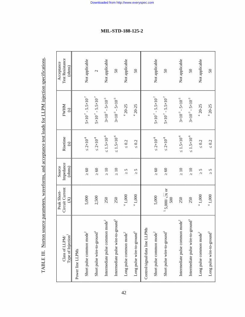
TAB
LE II
I. N
orto
n so
urce
par
amet
ers,
wav
efor
ms,
and
acc
epta
nce
test
load
s fo
r LLP
M in
ject
ion
spec
ifica
tions
.
Cla
ss o
f LLP
M/
Type
of I
njec
tion1
Peak
Sho
rt-C
ircui
t Cur
rent
(A)
Sour
ceIm
peda
nce
(ohm
s)R
iset
ime
(s)
FWH
M(s
)
Acc
epta
nce
Test
Res
ista
nce
(ohm
s)
Pow
er li
ne L
LPM
s
Sh
ort p
ulse
com
mon
mod
e25,
000
≥ 60
≤ 2×
10-8
5×10
-7 -
5.5×
10-7
Not
app
licab
le
Sh
ort p
ulse
wire
-to-g
roun
d32,
500
≥ 60
≤ 2×
10-8
5×10
-7 -
5.5×
10-7
2
In
term
edia
te p
ulse
com
mon
mod
e225
0≥
10≤
1.5×
10-6
3×10
-3 -
5×10
-3N
ot a
pplic
able
In
term
edia
te p
ulse
wire
-to-g
roun
d325
0≥
10≤
1.5×
10-6
3×10
-3 -
5×10
-350
Lo
ng p
ulse
com
mon
mod
e24 1
,000
≥ 5
≤ 0.
24 2
0-25
Not
app
licab
le
Lo
ng p
ulse
wire
-to-g
roun
d34 1
,000
≥ 5
≤ 0.
24 2
0-25
50
Con
trol/s
igna
l/dat
a lin
e LL
PMs
Sh
ort p
ulse
com
mon
mod
e25,
000
≥ 60
≤ 2×
10-8
5×10
-7 -
5.5×
10-7
Not
app
licab
le
Sh
ort p
ulse
wire
-to-g
roun
d35 5
,000
/N
or50
0≥
60≤
2×10
-85×
10-7
- 5.
5×10
-750
In
term
edia
te p
ulse
com
mon
mod
e225
0≥
10≤
1.5×
10-6
3×10
-3 -
5×10
-3N
ot a
pplic
able
In
term
edia
te p
ulse
wire
-to-g
roun
d325
0≥
10≤
1.5×
10-6
3×10
-3 -
5×10
-350
Lo
ng p
ulse
com
mon
mod
e24 1
,000
≥ 5
≤ 0.
24
20-2
5N
ot a
pplic
able
Lo
ng p
ulse
wire
-to-g
roun
d34 1
,000
≥ 5
≤ 0.
24 2
0-25
50
42
MIL-STD-188-125-2
Downloaded from http://www.everyspec.com
TAB
LE II
I. N
orto
n so
urce
par
amet
ers,
wav
efor
ms,
and
acc
epta
nce
test
load
s fo
r LLP
M in
ject
ion
s
peci
ficat
ions
- C
ontin
ued.
Not
es.
1 Pul
sed
curr
ent i
njec
tion
spec
ifica
tions
are
def
ined
in te
rms
of th
e N
orto
n eq
uiva
lent
sou
rces
. D
oubl
e-ex
pone
ntia
lw
avef
orm
s ar
e us
ed in
all
LLPM
PC
I spe
cific
atio
ns.
Peak
sho
rt-ci
rcui
t cur
rent
is th
e pe
ak ti
me-
dom
ain
curr
ent i
nto
ash
ort-c
ircui
t cal
ibra
tion
load
at t
he p
ulse
r out
put t
erm
inal
s. S
ourc
e im
peda
nce
is th
e pu
lser
pea
k tim
e-do
mai
n op
en-
circ
uit v
olta
ge d
ivid
ed b
y th
e pe
ak ti
me-
dom
ain
shor
t-circ
uit c
urre
nt.
Ris
etim
e is
the
10-p
erce
nt to
90-
perc
ent r
iset
ime.
Full-
wid
th a
t hal
f-m
axim
um a
mpl
itude
(FW
HM
) is
the
time
inte
rval
bet
wee
n th
e 50
-per
cent
am
plitu
de p
oint
s.
The
sour
ce p
aram
eter
s ar
e ge
nera
lly s
peci
fied
by th
e m
inim
um a
ccep
tabl
e so
urce
impe
danc
e an
d th
e m
axim
umac
cept
able
rise
time.
Thi
s is
don
e fo
r the
sol
e pu
rpos
e of
exp
erim
enta
l pra
ctic
ality
, so
that
the
curr
ent i
njec
tion
sour
ces
are
not r
equi
red
to p
reci
sely
mat
ch p
resc
ribed
wav
efor
ms.
2 For
a c
omm
on m
ode
test
, all
cond
ucto
rs in
the
cabl
e ar
e si
mul
tane
ousl
y dr
iven
with
resp
ect t
o th
e LL
PM g
roun
dco
nnec
tion
poin
t. C
omm
on m
ode
test
ing
is re
quire
d fo
r ver
ifica
tion,
but
is n
ot re
quire
d fo
r acc
epta
nce.
3 Fo
r a w
ire-to
-gro
und
test
, eac
h of
the
cond
ucto
rs in
the
cabl
e is
indi
vidu
ally
driv
en w
ith re
spec
t to
the
LLPM
gro
und
conn
ectio
n po
int.
4 The
long
pul
se p
eak
shor
t-circ
uit c
urre
nt (1
,000
A) a
nd F
WH
M (2
0-25
s) a
re d
esig
n ob
ject
ives
. A
ny d
oubl
e-ex
pone
ntia
l wav
efor
m w
ith a
pea
k am
plitu
de ≥
200
A, r
iset
ime
≤ 0.
2 s,
and
pea
k cu
rren
t × F
WH
M p
rodu
ct ≥
2×1
04 A-s
satis
fies
the
min
imum
requ
irem
ent.
5 N is
the
num
ber o
f con
duct
ors
in th
e ca
ble.
The
larg
er o
f the
se tw
o am
plitu
des
is re
quire
d.
MIL-STD-188-125-2
43
Downloaded from http://www.everyspec.com
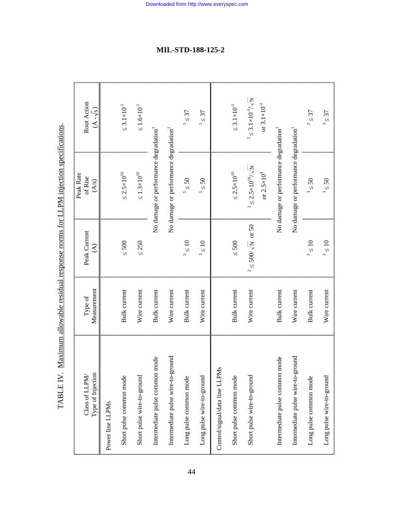
TAB
LE IV
. M
axim
um a
llow
able
resi
dual
resp
onse
nor
ms
for L
LPM
inje
ctio
n sp
ecifi
catio
ns.
Cla
ss o
f LLP
M/
Type
of I
njec
tion
Type
of
Mea
sure
men
tPe
ak C
urre
nt(A
)
Peak
Rat
eof
Ris
e(A
/s)
Roo
t Act
ion
(A -
s)
Pow
er li
ne L
LPM
s
Sh
ort p
ulse
com
mon
mod
eB
ulk
curr
ent
≤ 50
0≤
2.5×
1010
≤ 3.
1×10
-1
Sh
ort p
ulse
wire
-to-g
roun
dW
ire c
urre
nt≤
250
≤ 1.
3×10
10≤
1.6×
10-1
In
term
edia
te p
ulse
com
mon
mod
eB
ulk
curr
ent
No
dam
age
or p
erfo
rman
ce d
egra
datio
n1
In
term
edia
te p
ulse
wire
-to-g
roun
dW
ire c
urre
ntN
o da
mag
e or
per
form
ance
deg
rada
tion1
Lo
ng p
ulse
com
mon
mod
eB
ulk
curr
ent
3 ≤ 1
03 ≤
50
3 ≤ 3
7
Lo
ng p
ulse
wire
-to-g
roun
dW
ire c
urre
nt3
≤ 10
3 ≤ 5
03 ≤
37
Con
trol/s
igna
l/dat
a lin
e LL
PMs
Sh
ort p
ulse
com
mon
mod
eB
ulk
curr
ent
≤ 50
0≤
2.5×
1010
≤ 3.
1×10
-1
Sh
ort p
ulse
wire
-to-g
roun
dW
ire c
urre
nt2 ≤
500
/N
or 5
02
≤ 2.
5×10
10/
N
or 2
.5×1
09
2 ≤
3.1×
10-1
/N
or 3
.1×1
0-2
In
term
edia
te p
ulse
com
mon
mod
eB
ulk
curr
ent
No
dam
age
or p
erfo
rman
ce d
egra
datio
n1
In
term
edia
te p
ulse
wire
-to-g
roun
dW
ire c
urre
ntN
o da
mag
e or
per
form
ance
deg
rada
tion1
Lo
ng p
ulse
com
mon
mod
eB
ulk
curr
ent
3 ≤ 1
03
≤ 50
3 ≤ 3
7
Lo
ng p
ulse
wire
-to-g
roun
dW
ire c
urre
nt3 ≤
10
3 ≤
503 ≤
37
MIL-STD-188-125-2
44
Downloaded from http://www.everyspec.com
TAB
LE IV
. M
axim
um a
llow
able
resi
dual
resp
onse
nor
ms
for L
LPM
inje
ctio
n sp
ecifi
catio
ns -
Con
tinue
d.
Not
es.
1 Pas
s/fa
il cr
iteria
on
the
resi
dual
resp
onse
nor
ms
are
not s
peci
fied
for t
he in
term
edia
te p
ulse
cur
rent
inje
ctio
n te
stse
quen
ce.
The
pass
/fail
crite
ria o
f no
POE
prot
ectiv
e de
vice
dam
age
or p
erfo
rman
ce d
egra
datio
n al
so a
pplie
s to
PC
I tes
tse
quen
ces
whe
re th
is n
ote
does
not
app
ear i
n th
e ta
ble.
2 N is
the
num
ber o
f con
duct
ors
in th
e ca
ble.
The
larg
er o
f the
se tw
o am
plitu
des
is th
e m
axim
um a
llow
able
nor
m li
mit.
3 Th
e m
axim
um a
llow
able
nor
m li
mits
list
ed fo
r the
long
pul
se te
st s
eque
nce
assu
me
the
use
of a
1,0
00-A
driv
e pu
lse,
with
riset
ime
≤ 0.
2 s
and
FWH
M ≥
20
s. W
hen
othe
r allo
wed
driv
e pu
lses
are
use
d, th
e LL
PM is
requ
ired
to a
ttenu
ate
the
peak
cur
rent
, pea
k ra
te o
f ris
e, a
nd ro
ot a
ctio
n no
rms
by a
fact
or o
f at l
east
100
.
MIL-STD-188-125-2
45
Downloaded from http://www.everyspec.com
MIL-STD-188-125-2
46
(whichever is larger) and shall not cause unacceptable LLPM damage or performancedegradation5.
A Norton source with a 250-A short-circuit current, ≤ 1.5-µs risetime and 3-5-ms FWHM,and ≥ 10-Ω source impedance, connected to the long-line terminal of a control/signal/data lineLLPM, shall not cause unacceptable LLPM damage or performance degradation5.
A Norton source with a 1,000-A short-circuit current, ≤ 0.2-s risetime and 20-25-s FWHM,and ≥ 5-Ω source impedance, connected to the long-line terminal of a control/signal/data lineLLPM, shall produce a residual response stress at the intrasite terminal no greater than 10 A andshall not cause unacceptable LLPM damage or performance degradation5.
5.7.2.4 Acceptance testing of LLPMs. Acceptance testing of power line LLPMs andcontrol/signal/data line LLPMs shall be conducted using the PCI test procedures of Appendix B.All defects found during the acceptance testing shall be corrected, retested, and shown to providethe required performance.
5.8 Special protective measures. In special cases where HEMP hardness cannot be achievedwith the electromagnetic barrier alone (see 4.3.6), special protective measures shall beimplemented. Special protective measures shall not be used as a substitute for an electromagneticbarrier that satisfies the performance requirements of this standard.
5.8.1 MCE outside the subsystem electromagnetic barriers. Special protective measuresshall be implemented to HEMP harden MCE that are placed outside the subsystemelectromagnetic barriers IAW provisions of this standard (see 5.1.2). Special protective measuresfor MCE outside the subsystem electromagnetic barriers may include:
a. Cable, conduit, and local volume shielding,
b. Linear and nonlinear transient suppression/attenuation devices,
c. Equipment-level hardening measures (reduced coupling cross-section, dielectric means ofsignal and power transport, use of inherently robust components),
d. Remoting sensitive circuits to locations within a protected volume,
e. Automatic recycling features or operator intervention schemes, when the mission timelinepermits,
f. Other hardening measures appropriate for the particular equipment to be protected.
Downloaded from http://www.everyspec.com
MIL-STD-188-125-2
47
Performance requirements for the special protective measures shall ensure that the upper-bound,HEMP-induced peak time-domain current stresses at the equipment level are less than thevulnerability thresholds of the equipment6.
5.8.1.1 RF communications antennas outside the subsystem electromagnetic barriers.Mission-critical RF antennas and any associated antenna-mounted electronics, tuning circuits, andantenna cables located outside the subsystem electromagnetic barriers shall be HEMP hardened asMCE outside the subsystem electromagnetic barriers. Performance requirements for the specialprotective measures shall ensure that the upper-bound, HEMP-induced peak time-domain currentstresses at the equipment level are less than the vulnerability thresholds of the equipment6.
5.8.2. MCE that is inside a subsystem electromagnetic barrier and fails verification testing.Special protective measures shall be implemented to HEMP harden MCE that are placed insidethe subsystem electromagnetic barrier, but experience mission-aborting damage or upset duringverification testing. Special protective measures for MCE inside a subsystem electromagneticbarrier may include cable, conduit, and local volume shielding; transient suppression/attenuationdevices; equipment-level hardening measures; remoting sensitive circuits; automatic recyclingfeatures; operator intervention schemes; and other hardening measures appropriate for theparticular equipment to be protected. Performance requirements for the special protectivemeasures shall ensure that the upper-bound, HEMP-induced peak time-domain current stresses atthe equipment level are less than the vulnerability thresholds of the equipment6.
5.8.3 Special protective volumes.
5.8.3.1 Special protective volumes for piping POEs. When a piping POE WBC must belarger than the dimension corresponding to a cutoff frequency of at least 1.5 GHz to provideadequate fluid flow and a waveguide-below-cutoff array insert cannot be used, a specialprotective volume shall be established inside the main subsystem electromagnetic barrier (figure9a). The piping POE shall be protected with a special waveguide.
5.8.3.1.1 Special waveguide requirements. A WBC having a cutoff frequency less than1.5 GHz shall be of the minimum inside transverse dimension consistent with its functionalrequirements. The length of the special waveguide section shall be at least five times its maximuminside transverse dimension. All joints and couplings in the special waveguide section shall beelectromagnetically closed. No dielectric linings shall be permitted in the special waveguidesection. 6 See MIL-HDBK-423 for methods of determining the upper-bound HEMP-induced stresses and vulnerability thresholds.
Downloaded from http://www.everyspec.com
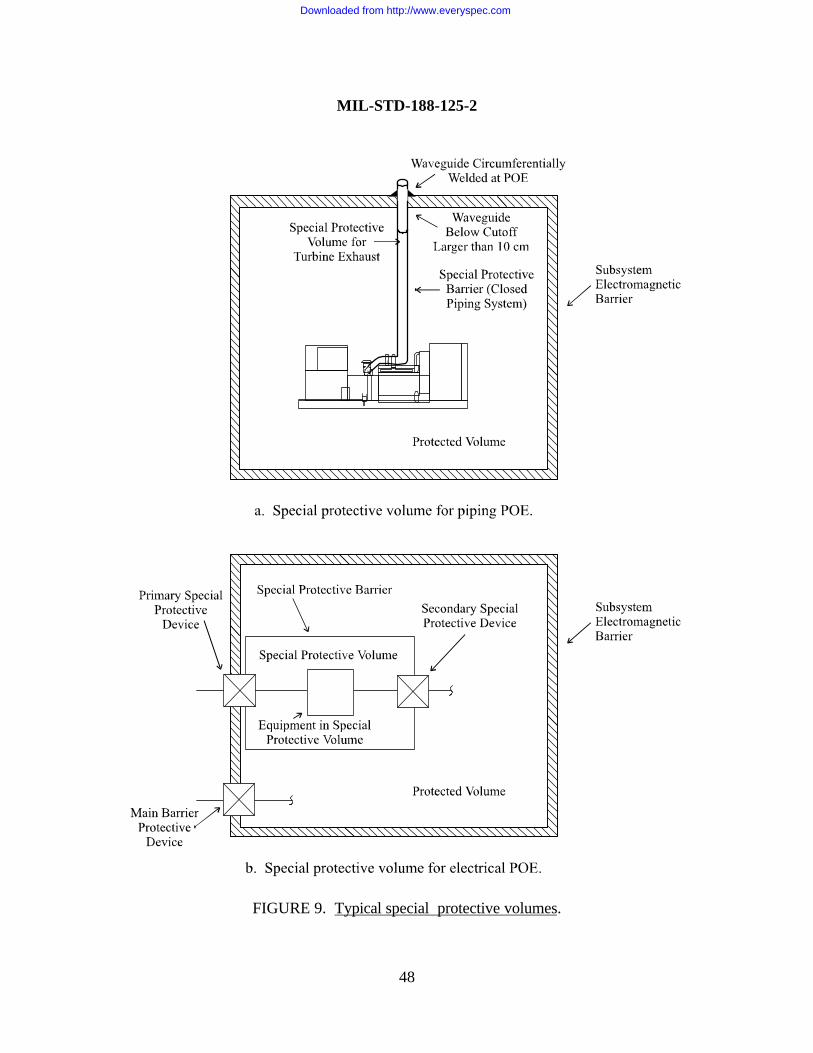
MIL-STD-188-125-2
48
FIGURE 9. Typical special protective volumes.
Downloaded from http://www.everyspec.com
MIL-STD-188-125-2
49
5.8.3.1.2 Special protective barriers for piping POEs. The special protective barrier shallcompletely enclose the piping that is protected at its POE with a waveguide below cutoff having acutoff frequency less than 1.5 GHz. The special protective barrier may be a separate shield withprotected penetrations, or it may be implemented using the metal walls of the closed pipingsystem itself. Performance requirements for the special protective barrier shall ensure that thetotal shielding effectiveness, measured through the main subsystem electromagnetic barrier andspecial protective barrier, satisfies at least the minimum requirements shown on figure 4.
5.8.3.2 Special protective volumes for electrical POEs. When an electrical POE protectivedevice cannot be designed to achieve the transient suppression/attenuation requirementsprescribed for the applicable class of electrical POE (see 5.7.1) without interfering withoperational signals it is required to pass, a special protective volume shall be established inside themain subsystem electromagnetic barrier (figure 9b). The electrical POE shall be protected with aprimary special electrical POE protective device.
5.8.3.2.1 Primary special electrical POE protective device requirements. A primary specialelectrical POE protective device shall be substituted for a main barrier protective device thatcannot achieve the prescribed transient suppression/attenuation performance (see 5.7.1) withoutinterfering with the operational signals it is required to pass. The primary special protectivedevice shall be designed to provide the maximum transient suppression/attenuation consistent withits functional requirements. A Norton source with pulse parameters prescribed for the applicableclass of electrical POE (see table I), connected to the penetrating conductor at the primary specialprotective device external terminal, shall produce a residual internal transient stress no greaterthan the design value for the associated special protective volume and shall not cause devicedamage or performance degradation4.
5.8.3.2.2 Secondary special electrical POE protective device requirements. When thecombination of the primary special electrical POE protective device and the directly connectedequipment cannot achieve the transient suppression/attenuation requirements for the applicableclass of electrical POE (see 5.7.1), a secondary special electrical POE protective device shall beprovided (figure 9b). Performance requirements for the secondary special protective device shallensure that the total transient suppression/attenuation through the primary special protectivedevice, the connected equipment, and the secondary special protective device satisfies at least theminimum requirements prescribed for the applicable class of electrical POE without devicedamage or performance degradation4.
5.8.3.2.3 Special protective barriers for electrical POEs. The special protective barrier shallcompletely enclose the wiring and equipment directly connected to the primary special electricalPOE protective device. The special protective barrier may be a separate shield with protected
Downloaded from http://www.everyspec.com
MIL-STD-188-125-2
50
penetrations, or it may be implemented using cable and conduit shields and equipment cabinets.Performance requirements for the special protective barrier shall ensure that the total shieldingeffectiveness, measured through the main subsystem electromagnetic barrier and specialprotective barrier, satisfies at least the minimum requirements shown on figure 4.
5.8.3.2.4 MCE in special protective volumes. Special protective measures shall beimplemented as necessary to HEMP harden MCE in a special protective volume to the HEMP-induced electromagnetic stresses that are allowable in that volume. Special protective measuresfor MCE in a special protective volume may include cable, conduit, and local volume shielding;transient suppression/attenuation devices; equipment-level hardening measures; remoting sensitivecircuits; automatic recycling features; operator intervention schemes; and other hardeningmeasures appropriate for the particular equipment to be protected. Performance requirements forthe special protective measures shall ensure that the upper-bound, HEMP-induced peak time-domain current stresses at the equipment level are less than the vulnerability thresholds of theequipment6.
5.8.4 Acceptance testing for special protective measures.
5.8.4.1 Special protective measures for MCE. Acceptance testing is not required forequipment-level special protective measures installed on MCE IAW 5.8.1, 5.8.2, and 5.8.3.2.4.HEMP hardness provided by these special protective measures shall be demonstrated during theverification test program.
5.8.4.2 Special protective barriers. Acceptance testing for all special protective barriersshall be conducted using shielding effectiveness test procedures of Appendix A. Additionally,acceptance testing for all primary and secondary special electrical POE protective devices shall beconducted using the PCI test procedures of Appendix B. All defects found during the acceptancetesting shall be corrected, retested, and shown to provide the required performance.
5.9 Reliability and maintainability. The HEMP protection shall be designed, fabricated, andassembled to be rugged, reliable, and maintainable. Reliability and maintainability tasks andrequirements shall be included in the system acquisition specifications to ensure that reliability isconsidered in component selections and assembly processes; to minimize the frequency,complexity, and costs of design-dictated maintenance; and to provide adequate provisioning withspare HCIs and maintenance tools and supplies.
5.10 Safety and human engineering. Safety and human engineering criteria, principles, andpractices shall be applied in the design, selection, and placement of the HEMP protectiveelements. Entryways shall be designed to accommodate the required traffic flow, and shieldeddoors shall operate simply with forces within human engineering limits. Inspection covers shall bedesigned for safety and ease of removal and proper reinstallation. Electrical POE protective
Downloaded from http://www.everyspec.com
MIL-STD-188-125-2
51
devices shall include fail-safe features, such as safety covers and capacitor discharge provisions,for protection of personnel during installation, operation, maintenance, and repairs.
5.11 Testability. The HEMP protection shall be designed, fabricated, and assembled toaccommodate quality assurance, acceptance, and verification testing and HM/HS. The subsystemHEMP shields shall be accessible for visual inspection at all POEs. Access for periodic shieldingeffectiveness measurements shall be provided. Electrical POE protective devices shall be installedwith accessible PCI drive points and measurement points.
5.12 Corrosion control. Corrosion protection measures shall be implemented in the design,
fabrication, and assembly of the HEMP protection. The subsystem HEMP shields and POEprotective devices shall be fabricated using inherently corrosion-resistant materials or shall becoated or metallurgically processed to resist corrosion. Joints between dissimilar metals shall beavoided and, where required, shall be provided with corrosion prevention treatments. Pocketswhere water or condensation can collect shall be avoided. Corrosion protection shall be providedfor conduits, cables, and connectors in the external cable plant. Cathodic protection shall beprovided, where required by environmental conditions at deployment sites.
5.13 Configuration management. A hardness configuration management program shall beimplemented during design, fabrication, and assembly of the HEMP protection. Hardness criticalitems and hardness critical processes shall be identified in the system drawings IAW MIL-STD-100, and installed HCIs shall be distinctively marked with Hardness Critical Labels, DD Forms2639, or Hardness Critical Tags, DD Forms 2640, as appropriate. System design, fabrication, andassembly changes shall be assessed for potential HEMP hardness impacts prior to approval. Theaffected portions of the HEMP protection shall be retested when major configuration changesoccur after acceptance testing.
5.14 Verification testing. After the HEMP protection has been accepted, the MCE has beeninstalled, and the system is operational, a verification test program shall be conducted. As aminimum, the verification testing shall include all of the procedures listed under Option A orunder Option B in table V. A combination of options, where some system elements areverification tested with the Option A procedures and the remaining elements are tested usingOption B procedures, is also permitted. All of the deficiencies identified by the verification testprogram shall be corrected and retested until the required hardness has been achieved.
5.14.1 CW immersion testing. CW immersion testing, when conducted as part of theverification test program, shall be performed IAW procedures of Appendix C. At frequencieswhere the measurement range exceeds the attenuation requirements shown on figure 4, ratios ofthe illuminating field strength to the residual internal field strength shall be greater than or equal tothe minimum shielding effectiveness requirement. Residual internal field strength shall be less thanor equal to the instrumentation noise or operating signal level at frequencies where the
Downloaded from http://www.everyspec.com
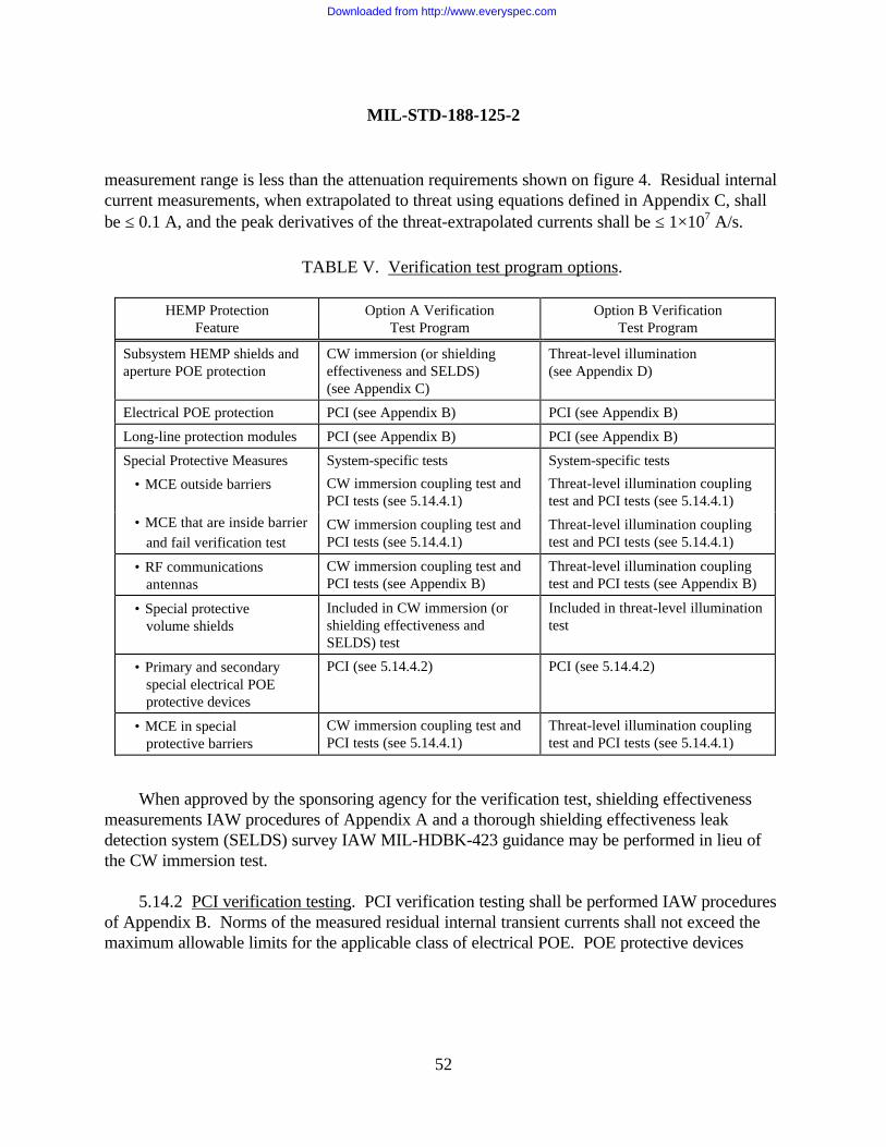
MIL-STD-188-125-2
52
measurement range is less than the attenuation requirements shown on figure 4. Residual internalcurrent measurements, when extrapolated to threat using equations defined in Appendix C, shallbe ≤ 0.1 A, and the peak derivatives of the threat-extrapolated currents shall be ≤ 1×10⁷ A/s.
When approved by the sponsoring agency for the verification test, shielding effectivenessmeasurements IAW procedures of Appendix A and a thorough shielding effectiveness leakdetection system (SELDS) survey IAW MIL-HDBK-423 guidance may be performed in lieu ofthe CW immersion test.
5.14.2 PCI verification testing. PCI verification testing shall be performed IAW proceduresof Appendix B. Norms of the measured residual internal transient currents shall not exceed themaximum allowable limits for the applicable class of electrical POE. POE protective devices
TABLE V. Verification test program options.
HEMP ProtectionFeature
Option A VerificationTest Program
Option B VerificationTest Program
Subsystem HEMP shields andaperture POE protection
CW immersion (or shieldingeffectiveness and SELDS)(see Appendix C)
Threat-level illumination(see Appendix D)
Electrical POE protection PCI (see Appendix B) PCI (see Appendix B)
Long-line protection modules PCI (see Appendix B) PCI (see Appendix B)
Special Protective Measures
• MCE outside barriers
System-specific tests
CW immersion coupling test andPCI tests (see 5.14.4.1)
System-specific tests
Threat-level illumination couplingtest and PCI tests (see 5.14.4.1)
• MCE that are inside barrier and fail verification test
CW immersion coupling test andPCI tests (see 5.14.4.1)
Threat-level illumination couplingtest and PCI tests (see 5.14.4.1)
• RF communications antennas
CW immersion coupling test andPCI tests (see Appendix B)
Threat-level illumination couplingtest and PCI tests (see Appendix B)
• Special protective volume shields
Included in CW immersion (orshielding effectiveness andSELDS) test
Included in threat-level illuminationtest
• Primary and secondary special electrical POE protective devices
PCI (see 5.14.4.2) PCI (see 5.14.4.2)
• MCE in special protective barriers
CW immersion coupling test andPCI tests (see 5.14.4.1)
Threat-level illumination couplingtest and PCI tests (see 5.14.4.1)
Downloaded from http://www.everyspec.com
MIL-STD-188-125-2
53
shall not be damaged or experience unacceptable performance degradation from the simulatedHEMP excitations. No mission-aborting damage or upsets of the MCE shall occur7.
5.14.3 Threat-level illumination testing. Threat-level illumination testing, when conductedas part of the verification test program, shall be performed IAW procedures of Appendix D. Theratio of the peak time-domain simulator incident field strength to the peak time-domain residualinternal field strength shall be ≥ 80 dB at each internal field measurement location. Peakamplitudes of the measured residual internal transient currents shall be ≤ 0.1 A, and the peakderivative of the measured transient currents shall be ≤ 1×10⁷ A/s. No mission-aborting damageor upsets of the MCE shall occur7.
5.14.4 Verification testing of special protective measures. System-specific procedures forverification testing of special protective measures shall be developed, based upon the testapproaches in paragraphs 5.14.4.1 and 5.1.14.2. The verification testing shall demonstrate thatHEMP-induced electromagnetic stresses resulting from system exposure to the threatenvironment of MIL-STD-2169 will not cause mission-aborting damage or upsets of the MCE7.
5.14.4.1 Verification testing of MCE hardened with special protective measures.Verification testing of MCE hardened with special protective measures shall generally includecoupling measurements and pulsed current injection testing. The system excitation for thecoupling measurements shall be provided using CW immersion, threat-level illumination, subthreattransient field illumination, CW or pulsed current injection, or other threat-relatable methods.MCE cable currents shall be measured and extrapolated to the upper-bound HEMP-inducedresponses for the MIL-STD-2169 threat environment. The extrapolation shall include a factor of10 to account for uncontrollable coupling parameters, such as departure from planarity andground conductivity, and other uncertainties. The upper-bound HEMP-induced currents shallthen be used as the drive levels for the pulsed current injection testing.
Long lines that connect to the MCE via LLPMs shall be tested with injected pulses of theamplitudes and waveforms prescribed in Appendix B for the applicable classes of LLPMs.Intrasite conductors that connect to the MCE and are directly exposed to the HEMP environmentshall be tested with injected pulses of the amplitudes and waveforms prescribed for PCI testing ofthe applicable classes of electrical POE protective devices.
Cables that connect or are internal to the MCE and are not directly exposed to the HEMPenvironment shall be tested with injected pulses having characteristics that comply with one of thefollowing requirements:
7 The determination whether observed damage or upsets are mission-aborting is the responsibility of the operational authorityfor the system.
Downloaded from http://www.everyspec.com
MIL-STD-188-125-2
54
a. Amplitudes equal to the upper-bound, HEMP-induced peak time-domain currentstresses, and waveforms similar to those of the applicable threat-extrapolated currents,
b. Amplitudes and waveforms prescribed for PCI testing of the applicable classes ofelectrical POE protection devices.
These verification test excitations shall not cause mission-aborting damage or upsets of theMCE7.
5.14.4.2 Verification testing of special protective barriers. Verification testing of specialprotective barriers shall include tests on the special protective barrier shield and penetrationprotective devices. During the system CW immersion test (see 5.14.1) or system threat-levelillumination test (see 5.14.3), measurements for verifying the performance of special protectiveshields and aperture penetration protection treatments shall be acquired, analyzed, and shown toprovide at least the required shielding effectiveness.
Verification testing of primary and secondary special electrical POE protective devices shallbe performed IAW procedures of Appendix B. In addition to the measurements in the specialprotective volume and functional observations required by 5.14.4.1, residual internal transientstresses shall be measured on conductors that penetrate from the special protective volume intothe protected volume. Norms of the responses at test points within the protected volume shall notexceed the applicable maximum allowable limits, and the test excitations shall not cause mission-aborting damage or upsets of the MCE7.
5.15 HM/HS program requirements. Logistics support analysis for the HEMP protectionmeasures shall be performed during the system acquisition phase. The logistics support analysisshall define the HM/HS requirements, supply support requirements, training requirements, andtechnical data requirements for the HEMP protection.
5.15.1 Hardness surveillance/reverification test procedures. Detailed hardness surveillance/reverification test procedures for the HEMP protection shall be provided. The HS tasks shall beperformed on a periodic basis, as specified in the HM/HS program. The reverification test resultsshall be correlatable to the verification test results and shall have the same pass/fail criteria. Theprocedures shall identify the tests to be conducted, frequency of testing, test equipmentrequirements, safety precautions, and other relevant information.
5.15.2 Maintenance and inspection procedures. Detailed procedures for preventivemaintenance and inspection and for repair and replacement of HEMP hardness critical assembliesor items shall be provided. Preventive maintenance and inspection procedures shall be designed,where practical, to be implemented at the organizational level and shall define the tasks to beperformed; frequency of performance; pass/fail criteria, where applicable; safety precautions, and
Downloaded from http://www.everyspec.com
MIL-STD-188-125-2
55
other relevant information. Repair and replacement procedures shall identify the tasks to beperformed; hardness requirements, including pass/fail criteria and post-repair test requirements;safety precautions; and other relevant information.
5.15.3 Supply support requirements. A parts list of the installed HEMP hardness criticalassemblies and items and lists of recommended organizational HEMP protection spare parts,repair parts, supplies, special tools, and special test equipment shall be provided. The lists shallidentify the nomenclature or description of each item; the manufacturer and manufacturer’s partnumber; the federal stock number, when assigned; the required quantity; and other relevantinformation. All spare hardness critical assemblies and items shall be marked using HardnessCritical Labels, DD Forms 2639, or Hardness Critical Tags, DD Forms 2640, as appropriate.
5.15.4 Training requirements. HEMP training requirements for operators and maintenancepersonnel assigned to the hardened system shall be defined. As a minimum, the training programshall include organizational HEMP awareness training for all system personnel and classroom andon-the-job training for HM/HS personnel. Training materials shall be provided for all training tobe administered at the organizational level.
5.15.5 Technical data. A HEMP protection technical manual shall be provided. As aminimum, the technical manual shall include the following:
a. Description and principles of operation of the HEMP protection,
b. HCI maintenance and inspection procedures, repair and replacement procedures, andhardness surveillance/reverification test procedures,
c. Supply support requirements,
d. Training requirements.
5.15.6 Delivery. The HEMP protection technical manual shall be delivered with the system.Recommended organizational HEMP spare parts, repair parts, supplies, special tools, special testequipment, and training materials shall also be delivered with the system.
5.15.7 Implementation. Preventive maintenance, inspections, and hardness surveillance/reverification testing shall be performed IAW the technical manual. Corrective maintenance shallbe performed if the performance of the HEMP protection degrades below the minimumrequirements of this standard. Hardness surveillance/reverification testing shall be performed atintervals not exceeding seven years.
Downloaded from http://www.everyspec.com
MIL-STD-188-125-2
56
6.0 NOTES
(This section contains information of a general or explanatory nature that may be helpful, but isnot required.)
6.1 Intended use. This standard contains minimum requirements and design objectives forlow-risk HEMP protection of transportable ground-based systems that perform critical, time-urgent C4I missions. The purpose is to standardize design, fabrication, assembly, and testing ofthe HEMP protection for these systems and to thereby ensure the quality and durability of thehardening.
Low-risk HEMP protection is military unique because it is required only for critical C4Iassets that support time-urgent attack warning and retaliatory military missions. While othermilitary and commercial systems may require HEMP protection, there are no commercialrequirements for low-risk hardening.
6.2 Issue of DoDISS. When this standard is used in acquisition, the applicable issue of theDoDISS must be cited in the solicitation (see 2.2.1 and 2.3).
6.3 Subject term (key word) listing.
Continuous wave immersionElectromagnetic barrierElectric surge arresterHardeningHardness verificationHigh-altitude electromagnetic pulseLow-risk HEMP protectionMission-critical equipmentNuclear survivabilityPoint-of-entryPOE protective devicePulsed current injectionShielding effectivenessSpecial protective measuresSubsystem HEMP shieldSurvivability/vulnerabilityTransient suppression/attenuation deviceWaveguide below cutoff
Downloaded from http://www.everyspec.com
MIL-STD-188-125-2
APPENDIX A
57
SHIELDING EFFECTIVENESS (SE) TEST PROCEDURESFOR TRANSPORTABLE GROUND-BASED SYSTEMS
A.1 GENERAL
A.1.1 Scope. This Appendix is a mandatory part of this standard. The informationcontained herein is intended for compliance. This Appendix establishes procedures for measuringthe shielding effectiveness of the electromagnetic barriers required for low-risk high-altitudeelectromagnetic pulse (HEMP) protection of transportable ground-based systems with critical,time-urgent missions. The procedures are applicable for testing other HEMP-hardened systems,when specified by the procurement documentation.
A.1.2 Applications. These procedures shall be used for shielding effectiveness acceptancetesting of the subsystem shields and aperture point-of-entry (POE) protective treatments. Theprocedures shall also be performed for acceptance of repairs or installations of new POEprotective devices after subsystem shield acceptance, except that only areas affected by the repairsor installations are required to be tested. Shielding effectiveness measurements may also beconducted as part of the verification test program.
A.2 REFERENCED DOCUMENTS
A.2.1 Government documents. The following Government documents form a part of thisAppendix to the extent specified:
DI-NUOR-80928 – Nuclear Survivability Test Plan
DI-NUOR-80929A – Nuclear Survivability Test Report
DNA-EMP-1 – Electromagnetic Pulse (EMP) Security ClassificationGuide (U) (document is classified S-RD)
(Copies of documents required by contractors in connection with specific acquisition functionsshould be obtained from the contracting activity or as directed by the contracting officer.)
A.2.2 Non-Government publications. The following publications form a part of thisAppendix to the extent specified:
IEEE-Std-299 – Standard for Measuring the Effectiveness ofElectromagnetic Shielding Enclosures
Downloaded from http://www.everyspec.com
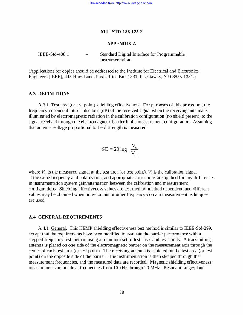
MIL-STD-188-125-2
APPENDIX A
58
IEEE-Std-488.1 – Standard Digital Interface for ProgrammableInstrumentation
(Applications for copies should be addressed to the Institute for Electrical and ElectronicsEngineers [IEEE], 445 Hoes Lane, Post Office Box 1331, Piscataway, NJ 08855-1331.)
A.3 DEFINITIONS
A.3.1 Test area (or test point) shielding effectiveness. For purposes of this procedure, thefrequency-dependent ratio in decibels (dB) of the received signal when the receiving antenna isilluminated by electromagnetic radiation in the calibration configuration (no shield present) to thesignal received through the electromagnetic barrier in the measurement configuration. Assumingthat antenna voltage proportional to field strength is measured:
SE 20 logVV
c
m
=
where Vm is the measured signal at the test area (or test point), Vc is the calibration signalat the same frequency and polarization, and appropriate corrections are applied for any differencesin instrumentation system gain/attenuation between the calibration and measurementconfigurations. Shielding effectiveness values are test method-method dependent, and differentvalues may be obtained when time-domain or other frequency-domain measurement techniquesare used.
A.4 GENERAL REQUIREMENTS
A.4.1 General. This HEMP shielding effectiveness test method is similar to IEEE-Std-299,except that the requirements have been modified to evaluate the barrier performance with astepped-frequency test method using a minimum set of test areas and test points. A transmittingantenna is placed on one side of the electromagnetic barrier on the measurement axis through thecenter of each test area (or test point). The receiving antenna is centered on the test area (or testpoint) on the opposite side of the barrier. The instrumentation is then stepped through themeasurement frequencies, and the measured data are recorded. Magnetic shielding effectivenessmeasurements are made at frequencies from 10 kHz through 20 MHz. Resonant range/plane
Downloaded from http://www.everyspec.com
MIL-STD-188-125-2
APPENDIX A
59
wave shielding effectiveness is measured from 20 MHz through 1 GHz. Selections of test areasand test points, test frequencies, and polarizations of the antennas are defined in this Appendix.
A.4.2 Purpose. These procedures define shielding effectiveness, as used in this standard.The purpose of the measurements is to obtain shielding effectiveness data for demonstratingcompliance with subsystem HEMP shield and aperture POE treatment performance requirements.
A.4.3 Subsystem HEMP protection test configuration. The shielding effectivenessacceptance test shall be conducted after fabrication and assembly of each subsystem HEMP shield,when the following prerequisite conditions are met. The HEMP shield assembly shall becomplete. All POEs and their POE protective devices that are required as part of the shieldassembly work shall be installed and in a normal operating condition. External wiring toconductive POE protective devices shall be disconnected. The test shall be performed beforeinstallation of the interior cabling, interior equipment, and interior finish work. A visual shieldinspection shall be performed before starting the measurements to ensure that these configurationrequirements have been met.
When shielding effectiveness measurements are performed as part of the verification testprogram, the subsystem under test shall be provided with electrical power and equipment in theprotected volume shall be turned “on.” The subsystem HEMP protection shall be intact.
A.4.4 Analysis requirements. No pretest or post-test analyses are required for theseprocedures.
A.4.5 Test equipment requirements. Antennas and other test equipment requirements forthese shielding effectiveness measurements are identified in table A-I. A typical instrumentationsystem is illustrated in figure A-1.
A.4.6 Operational impact analysis and risk. The electromagnetic barrier must remain intactduring conduct of the shielding effectiveness measurement sequence. Use of electrically noisyequipment must be restricted, so that adequate signal-to-noise ratio (SNR) and measurementrange of the test equipment are maintained. Manufacturing activity in the area or unusualoperations, such as modifications or maintenance, may therefore be affected. Radiated signallevels are low and present no hazard to equipment, but frequency adjustments may be required toavoid interference with nearby systems. Normal electrical safety precautions apply. As required,radio frequency radiation protection shall be provided for test personnel.
Downloaded from http://www.everyspec.com
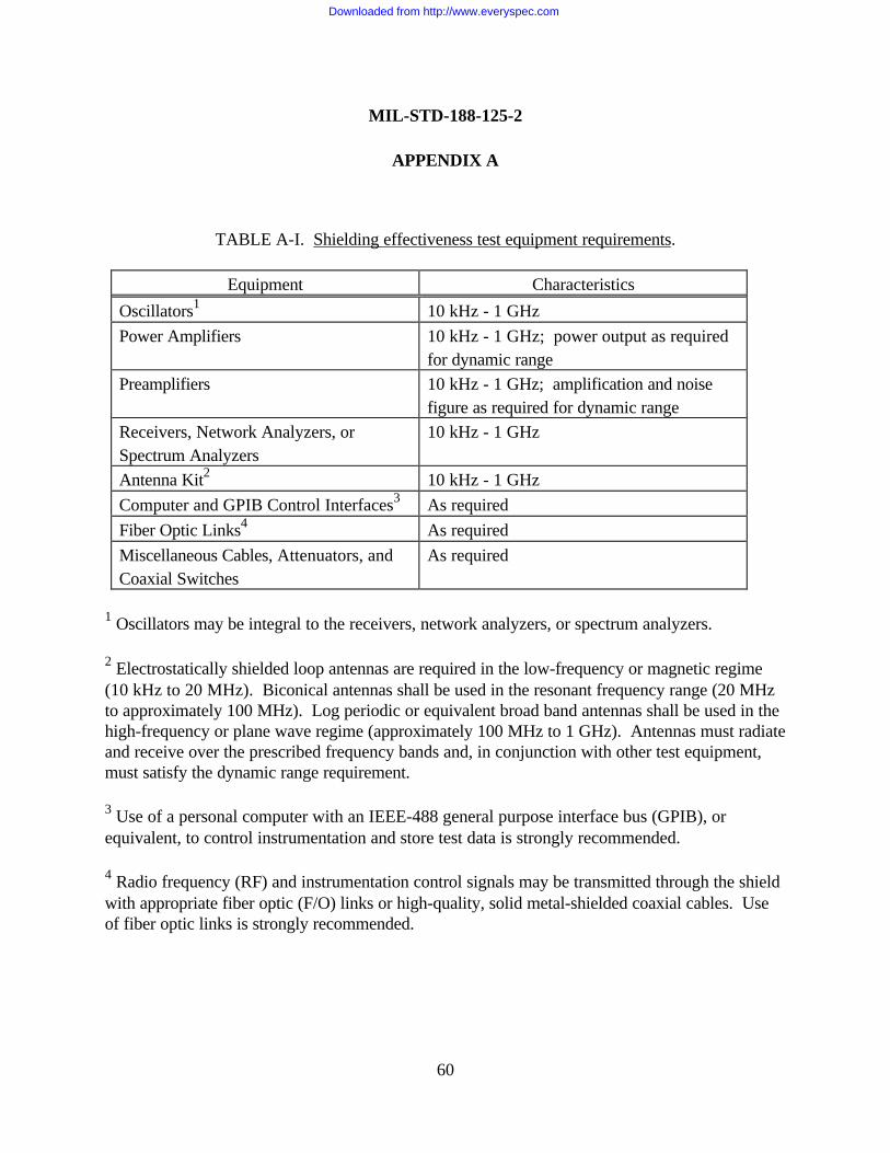
MIL-STD-188-125-2
APPENDIX A
60
TABLE A-I. Shielding effectiveness test equipment requirements.
Equipment CharacteristicsOscillators1 10 kHz - 1 GHzPower Amplifiers 10 kHz - 1 GHz; power output as required
for dynamic rangePreamplifiers 10 kHz - 1 GHz; amplification and noise
figure as required for dynamic rangeReceivers, Network Analyzers, orSpectrum Analyzers
10 kHz - 1 GHz
Antenna Kit2 10 kHz - 1 GHzComputer and GPIB Control Interfaces3 As requiredFiber Optic Links4 As requiredMiscellaneous Cables, Attenuators, andCoaxial Switches
As required
1 Oscillators may be integral to the receivers, network analyzers, or spectrum analyzers.
2 Electrostatically shielded loop antennas are required in the low-frequency or magnetic regime(10 kHz to 20 MHz). Biconical antennas shall be used in the resonant frequency range (20 MHzto approximately 100 MHz). Log periodic or equivalent broad band antennas shall be used in thehigh-frequency or plane wave regime (approximately 100 MHz to 1 GHz). Antennas must radiateand receive over the prescribed frequency bands and, in conjunction with other test equipment,must satisfy the dynamic range requirement.
3 Use of a personal computer with an IEEE-488 general purpose interface bus (GPIB), orequivalent, to control instrumentation and store test data is strongly recommended.
4 Radio frequency (RF) and instrumentation control signals may be transmitted through the shieldwith appropriate fiber optic (F/O) links or high-quality, solid metal-shielded coaxial cables. Useof fiber optic links is strongly recommended.
Downloaded from http://www.everyspec.com
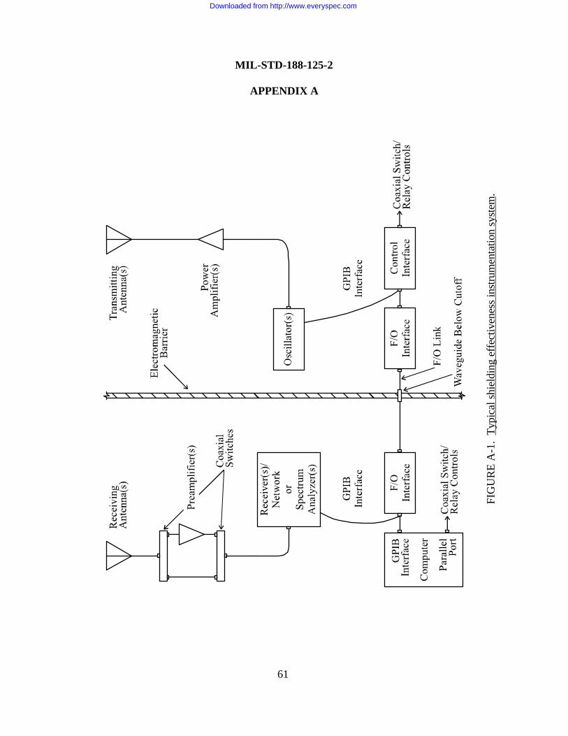
FIG
UR
E A
-1.
Typi
cal s
hiel
ding
eff
ectiv
enes
s in
stru
men
tatio
n sy
stem
.
MIL-STD-188-125-2
APPENDIX A
61
Downloaded from http://www.everyspec.com
MIL-STD-188-125-2
APPENDIX A
62
A.4.7 Test plan and procedures. A shielding effectiveness test plan and detailed testprocedures shall be prepared. These may be combined in a single document, or two separatedocuments may be used. As a minimum, the documentation shall contain the followinginformation:
a. Statement of test objectives.
b. System identification and description.
c. Test area identification. The entire surface of the electromagnetic barrier (including thefloor shield when both sides are accessible) shall be divided into numbered plane areas no greaterthan 2.5 m x 2.5 m (8.2 ft x 8.2 ft), as illustrated in figure A-2. Whenever practical, test areasshall be centered on the principal seams of the shield. The shielding effectiveness measurementaxis, which is the imaginary line between the transmitting antenna and receiving antenna locations,for each test area shall be normal to the shield surface and shall pass through the geometric centerof the area. A list of POEs by test area shall be provided.
d. Test point identification. Numbered test points shall be established at all architectural,mechanical, and electrical POEs. The measurement axes for test points shall be normal to theshield surface at the geometric centers of shielded doors, equipment access panels, and ventilationwaveguide-below-cutoff arrays and at the centerlines of penetrating pipes or conduits for pipingand electrical POEs.
e. Identification of test frequencies.
f. Test equipment identification by manufacturer, model and serial numbers, and detailedcalibration procedures.
g. Detailed measurement procedures.
h. Procedures for marking, repairing, and retesting defects.
i. Any deviations from the requirements of this Appendix.
j. Data management (including data quality control procedures, data acceptability criteria,annotation and preservation of data records, and pass/fail criteria).
k. Safety, including electromagnetic radiation and electrical shock hazards.
Downloaded from http://www.everyspec.com
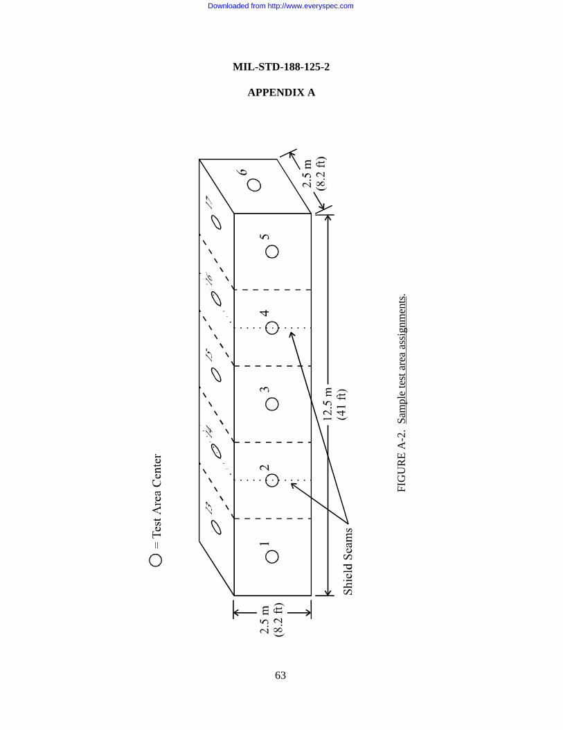
FIG
UR
E A
-2.
Sam
ple
test
are
a as
sign
men
ts.
MIL-STD-188-125-2
APPENDIX A
63
Downloaded from http://www.everyspec.com
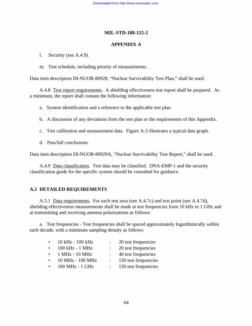
MIL-STD-188-125-2
APPENDIX A
64
l. Security (see A.4.9).
m. Test schedule, including priority of measurements.
Data item description DI-NUOR-80928, “Nuclear Survivability Test Plan,” shall be used.
A.4.8 Test report requirements. A shielding effectiveness test report shall be prepared. Asa minimum, the report shall contain the following information:
a. System identification and a reference to the applicable test plan.
b. A discussion of any deviations from the test plan or the requirements of this Appendix.
c. Test calibration and measurement data. Figure A-3 illustrates a typical data graph.
d. Pass/fail conclusions.
Data item description DI-NUOR-80929A, “Nuclear Survivability Test Report,” shall be used.
A.4.9 Data classification. Test data may be classified. DNA-EMP-1 and the securityclassification guide for the specific system should be consulted for guidance.
A.5 DETAILED REQUIREMENTS
A.5.1 Data requirements. For each test area (see A.4.7c) and test point (see A.4.7d),shielding effectiveness measurements shall be made at test frequencies from 10 kHz to 1 GHz andat transmitting and receiving antenna polarizations as follows:
a. Test frequencies - Test frequencies shall be spaced approximately logarithmically withineach decade, with a minimum sampling density as follows:
• 10 kHz - 100 kHz : 20 test frequencies• 100 kHz - 1 MHz : 20 test frequencies• 1 MHz - 10 MHz : 40 test frequencies• 10 MHz - 100 MHz : 150 test frequencies• 100 MHz - 1 GHz : 150 test frequencies
Downloaded from http://www.everyspec.com
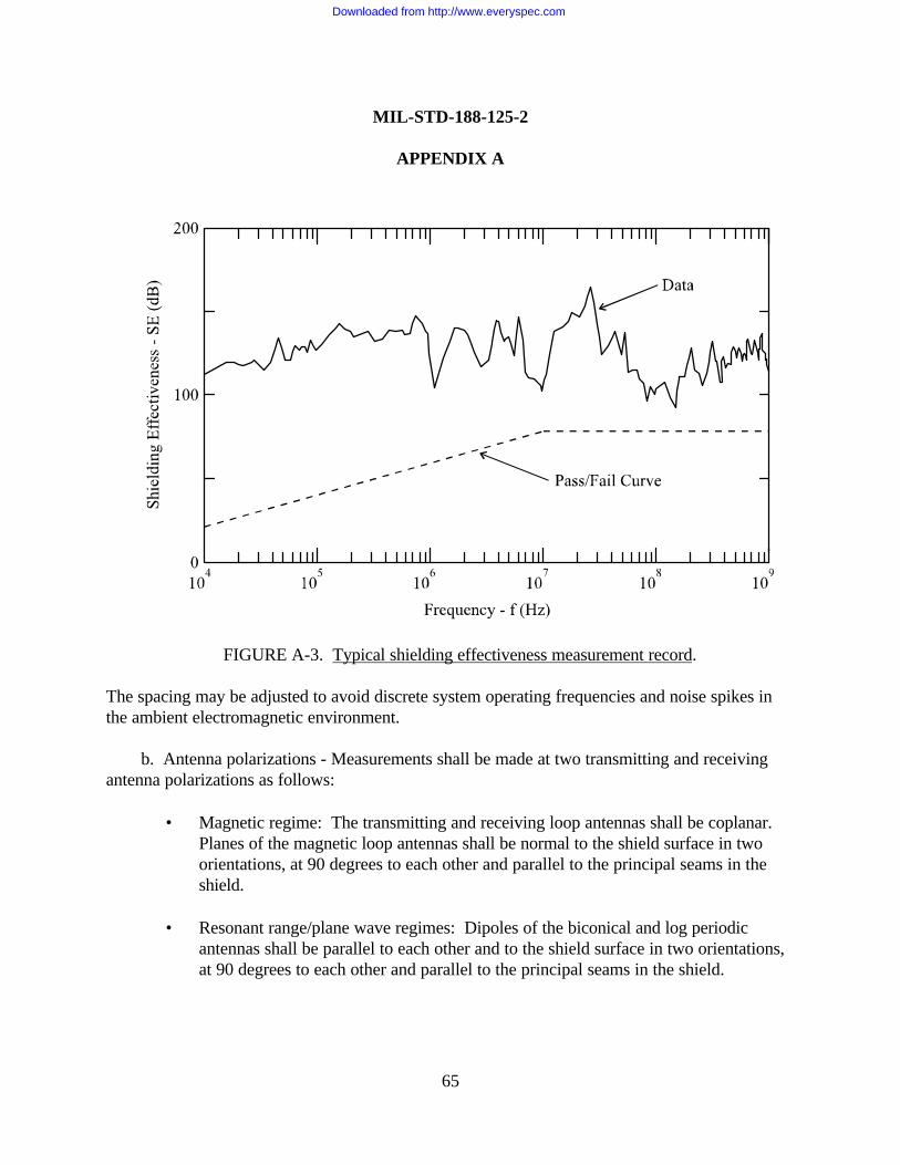
MIL-STD-188-125-2
APPENDIX A
65
The spacing may be adjusted to avoid discrete system operating frequencies and noise spikes inthe ambient electromagnetic environment.
b. Antenna polarizations - Measurements shall be made at two transmitting and receivingantenna polarizations as follows:
• Magnetic regime: The transmitting and receiving loop antennas shall be coplanar.Planes of the magnetic loop antennas shall be normal to the shield surface in twoorientations, at 90 degrees to each other and parallel to the principal seams in theshield.
• Resonant range/plane wave regimes: Dipoles of the biconical and log periodicantennas shall be parallel to each other and to the shield surface in two orientations,at 90 degrees to each other and parallel to the principal seams in the shield.
FIGURE A-3. Typical shielding effectiveness measurement record.
Downloaded from http://www.everyspec.com
MIL-STD-188-125-2
APPENDIX A
66
A.5.2 Calibration procedure. Calibrations at all test frequencies and at both antennapolarizations shall be performed as shown on figure A-4. The transmitting and receiving loopantennas shall be coplanar in the magnetic test regime, and the distance between antennas,measured between the centers of the loops, shall be 2.5 ± 0.05 m (8.2 ft ± 2 in). In theresonant/plane wave test regimes, dipoles of the transmitting and receiving biconical and logperiodic antennas shall be parallel to each other and the distance between antennas, measuredbetween the feedpoint connections to the antenna elements, shall be 2.5 ± 0.05 m.
During the calibration sequence, no equipment or other electromagnetic reflectors (exceptground) shall be closer to the antennas than three times the antenna separation. The antennasshall be at least 1.5 m (4.9 ft) above ground.
The instrumentation system shall be stepped through the test frequencies, and the receivedsignal strength at each test frequency and polarization shall be recorded as the calibration signal(Vc) for that configuration. Frequency stepping may be interrupted as necessary to performantenna and test equipment changes.
Instrumentation noise data shall also be acquired with the antennas in the calibrationconfigurations. The instrumentation system shall be stepped through the test frequencies, with thepower amplifiers deenergized The received signal strength at each test frequency and polarizationshall be recorded as the instrumentation noise signal (Vn) for that configuration. Frequencystepping may be interrupted as necessary to perform antenna and test equipment changes. Theinstrumentation dynamic range (DR) at each test frequency and polarization is defined as follows:
=
n
c
VV
log20DR
where corrections are applied for any differences in instrumentation system gain/attenuationbetween the calibration and instrumentation noise measurement configurations.
Test equipment shall be chosen to provide a dynamic range at least 20 dB in excess of theminimum shielding effectiveness requirement at every test frequency and antenna polarization.
A.5.3 Measurement procedure. Shielding effectiveness measurements for each testarea and test point and at all test frequencies and both required antenna polarizations shall be
Downloaded from http://www.everyspec.com
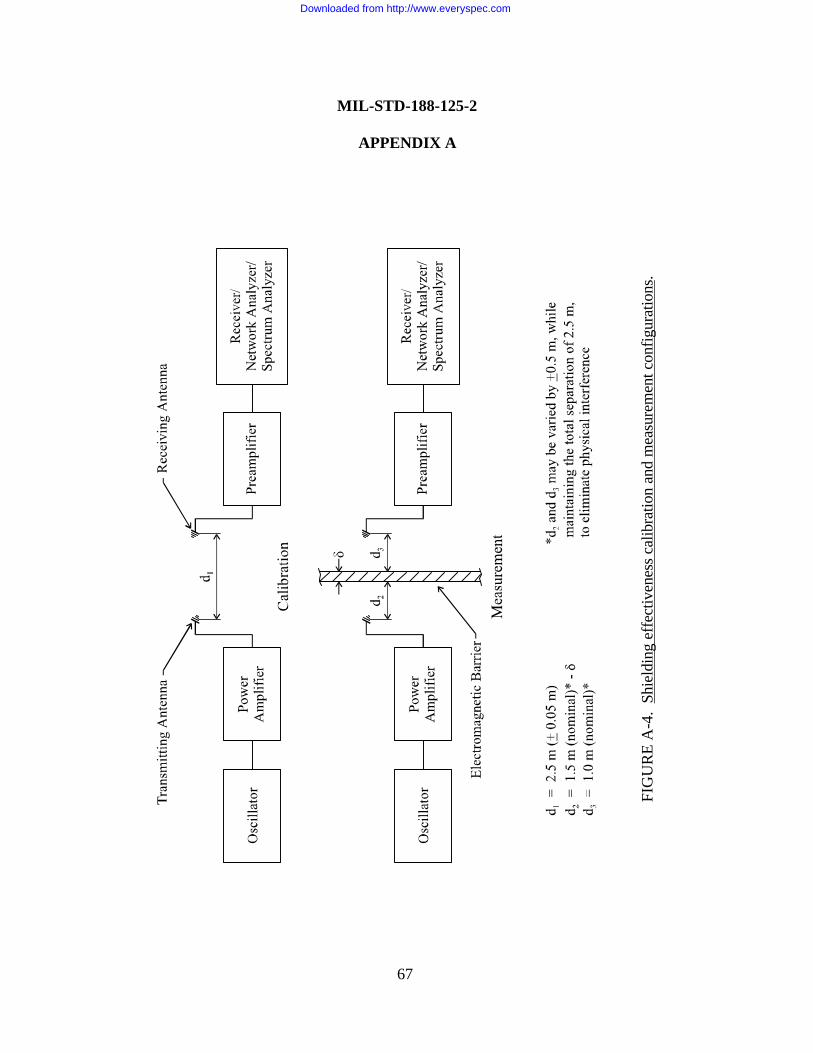
FIG
UR
E A
-4.
Shie
ldin
g ef
fect
iven
ess
calib
ratio
n an
d m
easu
rem
ent c
onfig
urat
ions
.
MIL-STD-188-125-2
APPENDIX A
67
Downloaded from http://www.everyspec.com
MIL-STD-188-125-2
APPENDIX A
68
performed as shown on figure A-4. Identical equipment, antennas, cables, and equipment settings(except gain/attenuator settings) shall be used in the calibration and measurement sequences.
The transmitting antenna should normally be placed outside the electromagnetic barrier,along the measurement axis centered on the test area (or test point). The receiving antenna shallbe on the opposite side of the barrier and shall be centered on the test area (or test point). Theloops of the transmitting and receiving loop antennas shall be coplanar in the magnetic testregime. Dipoles of the transmitting and receiving biconical and log periodic antennas shall beparallel to each other and parallel to the shield surface for the resonant range/plane wavemeasurements. The nominal distance from the transmitting antenna reference point (center of aloop antenna and feedpoint of a biconical or log periodic antenna) to the shield surface is 1.5 m(4.9 ft), less the thickness δ of the shield. The nominal distance from the receiving antennareference point to the shield surface is 1 m (3.3 ft), and at least 0.3-m (1-ft) clearance between theshield and the closest active point on the antenna shall be maintained. The transmitting andreceiving antenna distances from the shield may be varied by ± 0.5 m (1.6 ft), while maintainingthe total separation of 2.5 m, to eliminate physical interference. The measurement axis may alsobe displaced from the center of the test area (or test point) to eliminate physical interference ormaintain the receiving antenna clearance from the shield. These variations and displacements shallbe noted in the test report.
The instrumentation system shall be stepped through the test frequencies, and the receivedsignal strength at each test frequency and polarization shall be recorded as the measured signal(Vm) for that test area (or test point) and configuration. Frequency stepping may be interrupted asnecessary to perform antenna and test equipment changes.
A.5.4 System ambient noise measurement procedure. System ambient noise measurementsare not required, but are recommended at selected test areas (or test points) for characterizing theoperating electromagnetic environment within the subsystem protected volume and forinvestigating below-specification readings. Ambient noise measurements at a test area (or testpoint) are made with the receiving antennas at the same locations and in the same orientations asthose specified for shielding effectiveness measurements (see A.5.3). The instrumentation systemshall be stepped through the test frequencies, with the power amplifiers deenergized. Thereceived signal strength at each test frequency and polarization shall be recorded as the ambientnoise signal (Va) for that test area (or test point) and configuration. Frequency stepping may beinterrupted as necessary to perform antenna and test equipment changes. The systemmeasurement range (MR) at each test frequency and polarization is defined as follows:
Downloaded from http://www.everyspec.com
MIL-STD-188-125-2
APPENDIX A
69
MR 20 logVV
c
a
=
where corrections are applied for any differences in instrumentation system gain/attenuationbetween the calibration and ambient noise measurement configurations.
When system ambient noise limits the measurement range significantly below the requireddynamic range, the noise source should be eliminated if practical. Interference from narrow bandambient noise spikes can also be eliminated by adjusting the test frequency selection.
A.5.5 Pass/fail criteria8. The shielding effectiveness pass/fail criteria are shown as a functionof frequency on figure A-5. The subsystem HEMP shield and aperture POE protective treatmentsshall be considered satisfactory when both of the following criteria are met:
a. There is no series of measurements where the measured shielding effectiveness values arebelow the minimum requirements curve (figure A-5) at three consecutive frequencies.
b. No more than 10 percent of the measured shielding effectiveness values in anydecade (10 kHz - 100 kHz, 100 kHz - 1 MHz, 1 MHz - 10 MHz, 10 MHz - 100 MHz, and100 MHz - 1 GHz) are below the minimum requirements curve (figure A-5).
When making the pass/fail determination, below-specification shielding effectiveness valuescan be disregarded if it can be demonstrated that the reading is due to an ambient noise sourcethat cannot practically be eliminated.
A.5.6 Test failures. Any failure to satisfy the shielding effectiveness pass/fail criteria shall beconsidered a potential HEMP vulnerability. The cause of the potential vulnerability shall beinvestigated and corrected, if possible. After correction of the deficiency, the applicable portionof the shielding effectiveness test procedure shall be repeated.
8 For a test area (or test point) shielding effectiveness measurement taken inside a special protective volume, the pass/failcriteria are as specified for that special protective volume. Measurements in the adjacent protected volume are also required, todemonstrate that the total attenuation through the main barrier and special protective barrier satisfies the minimum requirementshown on figure A-5.
Downloaded from http://www.everyspec.com
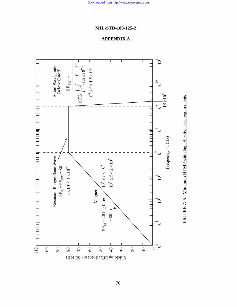
FIG
UR
E A
-5.
Min
imum
HEM
P sh
ield
ing
effe
ctiv
enes
s re
quire
men
ts.
MIL-STD-188-125-2
APPENDIX A
70
Downloaded from http://www.everyspec.com
MIL-STD-188-125-2
APPENDIX B
71
PULSED CURRENT INJECTION (PCI) TEST PROCEDURESFOR TRANSPORTABLE GROUND-BASED SYSTEMS
B.1 GENERAL
B.1.1 Scope. This Appendix is a mandatory part of this standard. The informationcontained herein is intended for compliance. This Appendix establishes pulsed current injectiontest procedures for electrical point-of-entry (POE) protective devices and long-line protectionmodules (LLPMs) required for low-risk high-altitude electromagnetic pulse (HEMP) protectionof transportable ground-based systems with critical, time-urgent missions. The procedures areapplicable for testing other HEMP-hardened systems, when specified by the procurementdocumentation.
B.1.2 Applications. These procedures shall be used for PCI acceptance testing afterinstallation of subsystem electrical POE protective treatments and LLPMs. The procedures shallalso be performed for PCI verification testing of electrical POE protective devices and LLPMsafter the system is completed and operational.
B.2 REFERENCED DOCUMENTS
B.2.1 Government documents. The following Government documents form a part of thisAppendix to the extent specified:
MIL-STD-2169 – High-Altitude Electromagnetic Pulse (HEMP)Environment (U) (document is classified Secret)
MIL-HDBK-423 – High-Altitude Electromagnetic Pulse (HEMP)Protection for Fixed and Transportable Ground-BasedFacilities, Volume I: Fixed Facilities
DI-NUOR-80928 – Nuclear Survivability Test Plan
DI-NUOR-80929A – Nuclear Survivability Test Report
DNA-EMP-1 – Electromagnetic Pulse (EMP) Security ClassificationGuide (U) (document is classified S-RD)
(Copies of documents required by contractors in connection with specific acquisition functionsshould be obtained from the contracting activity or as directed by the contracting officer.)
Downloaded from http://www.everyspec.com
MIL-STD-188-125-2
APPENDIX B
72
B.2.2 Non-Government publications. The following publication forms a part of thisAppendix to the extent specified:
IEEE-Std-488.1 – Standard Digital Interface for ProgrammableInstrumentation
(Applications for copies should be addressed to the Institute for Electrical and ElectronicsEngineers [IEEE], 445 Hoes Lane, Post Office Box 1331, Piscataway, NJ 08855-1331.)
B.3 DEFINITIONS
B.3.1 Norms. Scalar quantities that characterize the features of a complicated waveform.Norms used as pass/fail criteria for PCI test residual stresses are peak current, peak rate of rise,and root action. These quantities apply to the short pulse tests and long pulse tests only.
B.3.2 Peak current norm. The maximum absolute value of the amplitude of a currentwaveform I(t), expressed in units of amperes and measured from time t = 0 to t = 5 x 10⁻³ secondsfor the short pulse and from t = 0 to t = 100 seconds for the long pulse, where t = 0 at the start ofthe PCI drive.
B.3.3 Peak rate of rise norm. The maximum absolute value of the first derivative withrespect to time, dI/dt, of a current waveform, expressed in units of amperes per second andmeasured from time t = 0 to t = 5 x 10⁻³ seconds for the short pulse and from t = 0 to t = 100seconds for the long pulse, where t = 0 at the start of the PCI drive.
B.3.4 Root action norm. The root action norm of a current waveform I(t), in units ofamperes - seconds , is defined by the equation:
( )Root Action = do
Ι 2 t tτ
∫
where t = 0 at the start of the PCI drive pulse. τ equals 5x10⁻³ seconds for the short pulse and 100seconds for the long pulse.
Downloaded from http://www.everyspec.com
MIL-STD-188-125-2
APPENDIX B
73
B.4 GENERAL REQUIREMENTS
B.4.1 General. PCI acceptance testing is performed to demonstrate that electrical POEprotective devices and LLPMs, as installed, perform in accordance with the transientsuppression/attenuation requirements of this standard. PCI verification testing confirms thetransient suppression/attenuation performance in operational circuit configurations anddemonstrates that the mission-critical equipment (MCE) do not experience mission-abortingdamage or upsets as the result of the residual transient stresses.
This test method, for POE protective devices, couples threat-relatable transients topenetrating conductors at injection points outside the electromagnetic barrier. Injections arerequired in both common mode (all penetrating conductors of a cable simultaneously driven withrespect to ground) and individual wire-to-ground configurations. For purposes of this procedure,ground is a point on the subsystem HEMP shield in the vicinity of the POE protective deviceunder test. Residual internal transient stresses are measured and, during a verification test,operation of the MCE is monitored to determine if mission-aborting damage or upsets occur.
The required PCI tests are performed on each penetrating power line, control/signal/datacable and conductor, and radio frequency (RF) antenna cable core conductor and shield.Simultaneous injection of all subsystem electrical POE protective devices, if practical, is desirablefor verification testing. The PCI tests are also conducted on long-lines into each LLPM todemonstrate that the LLPM adequately isolates the intrasite cable plant from the reasonable worstcase long-line transients.
B.4.2 Purpose.
B.4.2.1 Purposes of PCI acceptance testing. The purposes of PCI testing, as an acceptancetest procedure, are as follows:
a. To measure the performance of as-installed conductive POE protective devices andLLPMs.
b. To demonstrate through post-test inspection, performance checks, and response dataanalysis that the protective devices will not be damaged or unacceptably degraded by threat-relatable transients.
c. To identify defective POE protective devices or LLPMs and faulty installation practices,so that repairs or replacements can be made.
Downloaded from http://www.everyspec.com
MIL-STD-188-125-2
APPENDIX B
74
B.4.2.2 Purposes of PCI verification testing. The purposes of PCI testing, as part of averification test program, are as follows:
a. To measure the performance of as-installed conductive POE protective devices andLLPMs.
b. To demonstrate through post-test inspection, performance checks, and response dataanalysis that the protective devices will not be damaged or unacceptably degraded by threat-relatable transients.
c. To identify defective POE protective devices or LLPMs and faulty installation practices,so that repairs or replacements can be made.
d. To characterize the residual transient stresses.
e. To demonstrate that the residual transient stresses will not cause mission-abortingdamage or upsets of the MCE in its various operating states.
f. To provide data for HEMP hardness assessment of the transportable system and baselinedata for the harness maintenance/hardness surveillance program.
B.4.3 Subsystem HEMP protection test configuration.
B.4.3.1 Acceptance test configuration. PCI testing for acceptance is performed after thePOE protective devices have been installed in the subsystems and after the LLPMs have beencompleted. The electromagnetic barrier is not required to be complete, but it must be recognizedthat an incomplete barrier may result in degradations of POE protective device performance andthe instrumentation system signal-to-noise ratio (SNR). Equipment that, in subsystem operation,will electrically connect to the POE protective device or LLPM under test are not required to beinstalled or powered.
B.4.3.2 Verification test configuration. When PCI verification testing is conducted, thesubsystem under test shall be in a normal operating configuration and shall be performing actualor simulated mission functions. The subsystem HEMP protection shall be intact. Equipment thatelectrically connects to the POE protective device or LLPM under test shall be powered andoperating, except as otherwise specified in this procedure.
B.4.4 Pretest analysis requirements. No pretest analyses are required for PCI acceptancetesting. Pretest analysis for PCI verification testing shall be performed to determine operatingstates in which the MCE will be tested. An equipment should be tested in multiple states when
Downloaded from http://www.everyspec.com
MIL-STD-188-125-2
APPENDIX B
75
the transition between states produces significantly different propagation paths for the residualtransient, significant changes in the equipment vulnerability threshold, or significant changes in thefunction being performed. A mission-critical transceiver should be tested in the transmitting andreceiving states, for example, and a digital interface should be tested in both the low and highsignal states.
B.4.5 Test equipment requirements. Test equipment required for PCI testing are identifiedin tables B-I and B-II. Table B-I lists the equipment required for testing electrical POE protectivedevices. The equipment required for testing LLPMs are listed in table B-II. Current injectionpulse generators are defined by their Norton equivalent circuits. Therefore, pulse generatorrequirements are stated in terms of the short-circuit current amplitude and waveform parametersand the source impedance. Short-circuit current is defined as current driven through a short-circuit calibration load connected to the generator output terminals. Source impedance is definedas the pulse generator peak open-circuit voltage divided by the peak short-circuit current.
B.4.6 Operational impact analysis and risk.
B.4.6.1 Acceptance testing impact When PCI testing is performed as an acceptance testprocedure, the electromagnetic barrier must remain reasonably intact, such that POE protectivedevice performance and instrumentation SNR ratio are not excessively degraded. The use ofelectrically noisy equipment must be restricted in order to achieve the required measurementsensitivity. Manufacturing activity in the area or unusual operations, such as modifications ormaintenance, may therefore be affected.
B.4.6.2 Verification testing impact. During PCI verification testing, the electromagneticbarrier must remain intact and use of electrically noisy equipment, which is not part of theoperational equipment suite, must be restricted in order to achieve the required measurementsensitivity. Manufacturing activity in the area or unusual operations, such as modifications ormaintenance, may therefore be affected. Mission operations can continue normally, except asfollows:
a. The circuit and POE protective device or LLPM under test may be unavailable fornormal use. It may be necessary to disconnect unprotected equipment outside the barrier, and thecircuit may be periodically deenergized.
b. A special sequence of activities may be required so that the circuits and system can betested in their various operating states.
Downloaded from http://www.everyspec.com
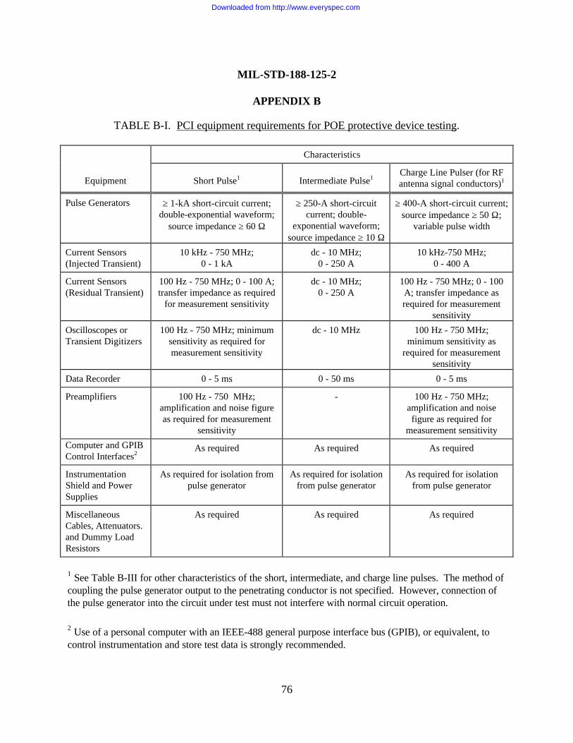
MIL-STD-188-125-2
APPENDIX B
76
TABLE B-I. PCI equipment requirements for POE protective device testing.
Characteristics
Equipment Short Pulse1 Intermediate Pulse1Charge Line Pulser (for RFantenna signal conductors)1
Pulse Generators ≥ 1-kA short-circuit current;double-exponential waveform;
source impedance ≥ 60 Ω
≥ 250-A short-circuitcurrent; double-
exponential waveform;source impedance ≥ 10 Ω
≥ 400-A short-circuit current;source impedance ≥ 50 Ω;
variable pulse width
Current Sensors(Injected Transient)
10 kHz - 750 MHz;0 - 1 kA
dc - 10 MHz;0 - 250 A
10 kHz-750 MHz;0 - 400 A
Current Sensors(Residual Transient)
100 Hz - 750 MHz; 0 - 100 A;transfer impedance as required
for measurement sensitivity
dc - 10 MHz;0 - 250 A
100 Hz - 750 MHz; 0 - 100A; transfer impedance asrequired for measurement
sensitivity
Oscilloscopes orTransient Digitizers
100 Hz - 750 MHz; minimumsensitivity as required formeasurement sensitivity
dc - 10 MHz 100 Hz - 750 MHz;minimum sensitivity as
required for measurementsensitivity
Data Recorder 0 - 5 ms 0 - 50 ms 0 - 5 ms
Preamplifiers 100 Hz - 750 MHz;amplification and noise figureas required for measurement
sensitivity
- 100 Hz - 750 MHz;amplification and noisefigure as required for
measurement sensitivity
Computer and GPIBControl Interfaces2
As required As required As required
InstrumentationShield and PowerSupplies
As required for isolation frompulse generator
As required for isolationfrom pulse generator
As required for isolationfrom pulse generator
MiscellaneousCables, Attenuators.and Dummy LoadResistors
As required As required As required
1 See Table B-III for other characteristics of the short, intermediate, and charge line pulses. The method ofcoupling the pulse generator output to the penetrating conductor is not specified. However, connection ofthe pulse generator into the circuit under test must not interfere with normal circuit operation.
2 Use of a personal computer with an IEEE-488 general purpose interface bus (GPIB), or equivalent, tocontrol instrumentation and store test data is strongly recommended.
Downloaded from http://www.everyspec.com
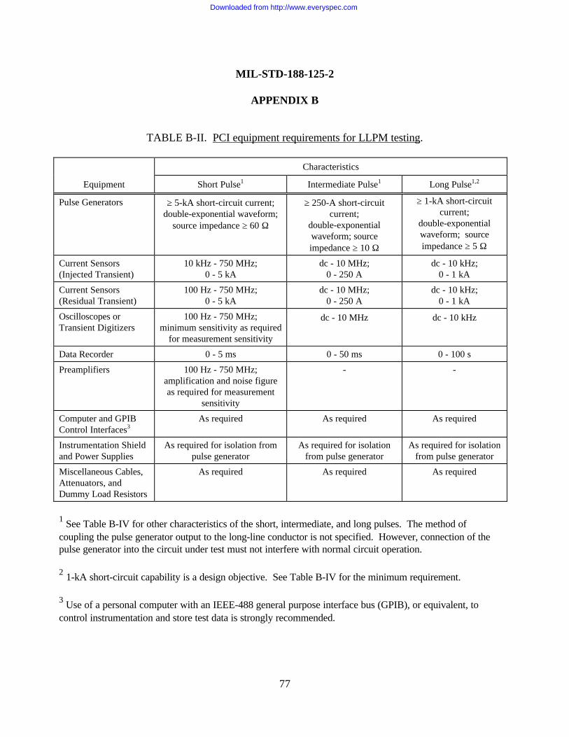
MIL-STD-188-125-2
APPENDIX B
77
TABLE B-II. PCI equipment requirements for LLPM testing.
Characteristics
Equipment Short Pulse1 Intermediate Pulse1 Long Pulse1,2
Pulse Generators ≥ 5-kA short-circuit current;double-exponential waveform;
source impedance ≥ 60 Ω
≥ 250-A short-circuitcurrent;
double-exponentialwaveform; sourceimpedance ≥ 10 Ω
≥ 1-kA short-circuitcurrent;
double-exponentialwaveform; sourceimpedance ≥ 5 Ω
Current Sensors(Injected Transient)
10 kHz - 750 MHz;0 - 5 kA
dc - 10 MHz;0 - 250 A
dc - 10 kHz;0 - 1 kA
Current Sensors(Residual Transient)
100 Hz - 750 MHz;0 - 5 kA
dc - 10 MHz;0 - 250 A
dc - 10 kHz;0 - 1 kA
Oscilloscopes orTransient Digitizers
100 Hz - 750 MHz;minimum sensitivity as required
for measurement sensitivity
dc - 10 MHz dc - 10 kHz
Data Recorder 0 - 5 ms 0 - 50 ms 0 - 100 s
Preamplifiers 100 Hz - 750 MHz;amplification and noise figureas required for measurement
sensitivity
- -
Computer and GPIBControl Interfaces3
As required As required As required
Instrumentation Shieldand Power Supplies
As required for isolation frompulse generator
As required for isolationfrom pulse generator
As required for isolationfrom pulse generator
Miscellaneous Cables,Attenuators, andDummy Load Resistors
As required As required As required
1 See Table B-IV for other characteristics of the short, intermediate, and long pulses. The method ofcoupling the pulse generator output to the long-line conductor is not specified. However, connection of thepulse generator into the circuit under test must not interfere with normal circuit operation.
2 1-kA short-circuit capability is a design objective. See Table B-IV for the minimum requirement.
3 Use of a personal computer with an IEEE-488 general purpose interface bus (GPIB), or equivalent, tocontrol instrumentation and store test data is strongly recommended.
Downloaded from http://www.everyspec.com
MIL-STD-188-125-2
APPENDIX B
78
B.4.6.3 Risk. PCI testing requires application of high voltages and large currents. Becauseof the high injection levels, the risk of damage to POE protective devices or other equipmentcannot be completely eliminated. However, the procedures are designed to minimize this risk.Special high-voltage electrical safety precautions are required. As required, radio frequencyradiation protection shall be provided for test personnel.
B.4.7 Test plan and procedures.
B.4.7.1 Acceptance test plan and procedures. A comprehensive, system-specific test planand detailed test procedures for PCI acceptance testing shall be prepared. These may becombined in a single document, or two separate documents may be used. As a minimum, thedocumentation shall contain the following information:
a. A statement of test objectives.
b. System, subsystem, and LLPM identification and descriptions (including drawings of thesubsystems showing the locations of all POEs, circuit diagrams of LLPMs that interface to thesubsystems under test, and a description of the HEMP protection measures).
c. Identification of the circuits and protective devices to be tested (including circuitfunctions and manufacturers’ data sheets and specifications for the protective devices).
d. HEMP simulation and data acquisition equipment descriptions (including manufacturer,model and serial numbers, characteristics, and detailed calibration procedures).
e. Identification of POE protective device injection points, injection levels and waveforms(see table B-III), and measurement points.
f. Identification of LLPM injection points, injection levels and waveforms (see table B-IV),and measurement points.
g. Detailed test procedures.
h. Any deviations from the requirements of this Appendix.
i. Data management (including data quality control procedures, data acceptability criteria,annotation and preservation of data records, and pass/fail criteria).
j. Safety, including electromagnetic radiation and electrical shock hazards.
Downloaded from http://www.everyspec.com
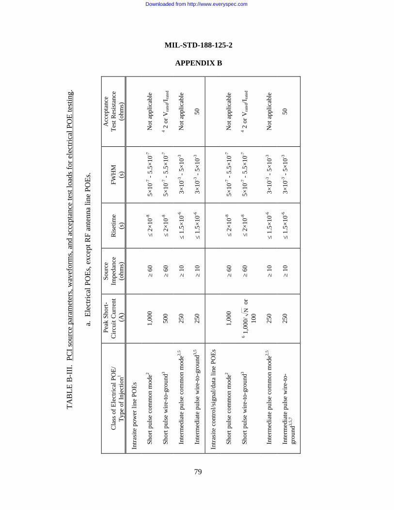
TAB
LE B
-III
. PC
I sou
rce
para
met
ers,
wav
efor
ms,
and
acc
epta
nce
test
load
s fo
r ele
ctric
al P
OE
test
ing.
a. E
lect
rical
PO
Es, e
xcep
t RF
ante
nna
line
POEs
.
Cla
ss o
f Ele
ctric
al P
OE/
Type
of I
njec
tion1
Peak
Sho
rt-C
ircui
t Cur
rent
(A
)
Sour
ceIm
peda
nce
(ohm
s)R
iset
ime
(s)
FWH
M(s
)
Acc
epta
nce
Test
Res
ista
nce
(ohm
s)
Intra
site
pow
er li
ne P
OEs
Sh
ort p
ulse
com
mon
mod
e21,
000
≥ 60
≤ 2×
10-8
5×10
-7 -
5.5×
10-7
Not
app
licab
le
Sh
ort p
ulse
wire
-to-g
roun
d350
0≥
60≤
2×10
-85×
10-7
- 5.
5×10
-74 2
or V
rate
d/Ira
ted
In
term
edia
te p
ulse
com
mon
mod
e2,5
250
≥ 10
≤ 1.
5×10
-63×
10-3
- 5×
10-3
Not
app
licab
le
In
term
edia
te p
ulse
wire
-to-g
roun
d3,5
250
≥ 10
≤ 1.
5×10
-63×
10-3
- 5×
10-3
50
Intra
site
con
trol/s
igna
l/dat
a lin
e PO
Es
Sh
ort p
ulse
com
mon
mod
e21,
000
≥ 60
≤ 2×
10-8
5×10
-7 -
5.5×
10-7
Not
app
licab
le
Sh
ort p
ulse
wire
-to-g
roun
d36 1
,000
/N
or
100
≥ 60
≤ 2×
10-8
5×10
-7 -
5.5×
10-7
4 2 o
r Vra
ted/I
rate
d
In
term
edia
te p
ulse
com
mon
mod
e2,5
250
≥ 10
≤ 1.
5×10
-63×
10-3
- 5×
10-3
Not
app
licab
le
In
term
edia
te p
ulse
wire
-to-
gr
ound
3,5,
725
0≥
10≤
1.5×
10-6
3×10
-3 -
5×10
-350
MIL-STD-188-125-2
APPENDIX B
79
Downloaded from http://www.everyspec.com
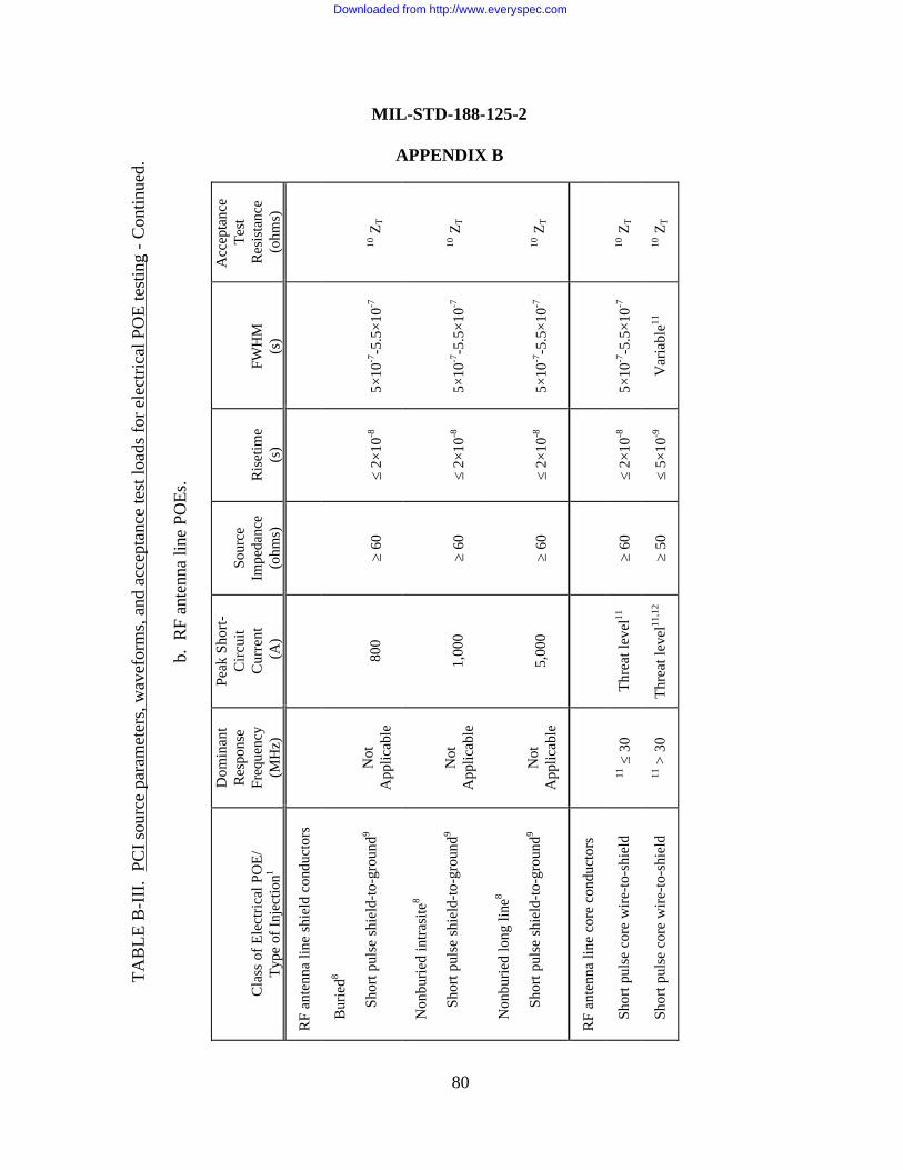
TAB
LE B
-III
. PC
I sou
rce
para
met
ers,
wav
efor
ms,
and
acc
epta
nce
test
load
s fo
r ele
ctric
al P
OE
test
ing
- Con
tinue
d.
b. R
F an
tenn
a lin
e PO
Es.
Cla
ss o
f Ele
ctric
al P
OE/
Type
of I
njec
tion1
Dom
inan
tR
espo
nse
Freq
uenc
y(M
Hz)
Peak
Sho
rt-C
ircui
tC
urre
nt (A
)
Sour
ceIm
peda
nce
(ohm
s)R
iset
ime
(s)
FWH
M(s
)
Acc
epta
nce
Test
Res
ista
nce
(ohm
s)
RF
ante
nna
line
shie
ld c
ondu
ctor
s
B
urie
d8
Shor
t pul
se s
hiel
d-to
-gro
und9
Not
App
licab
le80
0≥
60≤
2×10
-85×
10-7
-5.5
×10-7
10 Z
T
N
onbu
ried
intra
site
8
Shor
t pul
se s
hiel
d-to
-gro
und9
Not
App
licab
le1,
000
≥ 60
≤ 2×
10-8
5×10
-7-5
.5×1
0-710
ZT
N
onbu
ried
long
line
8
Shor
t pul
se s
hiel
d-to
-gro
und9
Not
App
licab
le5,
000
≥ 60
≤ 2×
10-8
5×10
-7-5
.5×1
0-710
ZT
RF
ante
nna
line
core
con
duct
ors
Sh
ort p
ulse
cor
e w
ire-to
-shi
eld
11 ≤
30
Thre
at le
vel11
≥ 60
≤ 2×
10-8
5×10
-7-5
.5×1
0-710
ZT
Sh
ort p
ulse
cor
e w
ire-to
-shi
eld
11 >
30
Thre
at le
vel11
,12
≥ 50
≤ 5×
10-9
Var
iabl
e1110
ZT
MIL-STD-188-125-2
APPENDIX B
80
Downloaded from http://www.everyspec.com
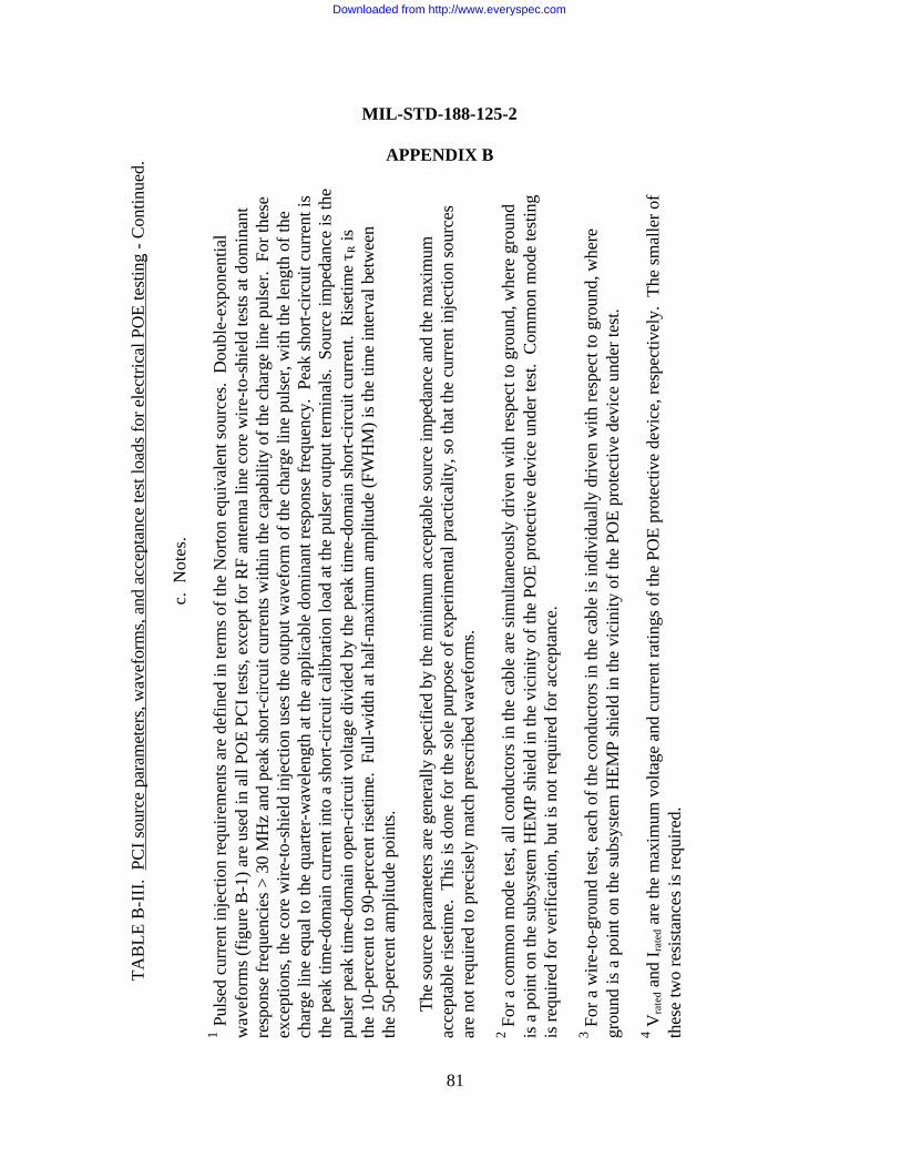
TAB
LE B
-III
. PC
I sou
rce
para
met
ers,
wav
efor
ms,
and
acc
epta
nce
test
load
s fo
r ele
ctric
al P
OE
test
ing
- Con
tinue
d.
c. N
otes
.
1 Pul
sed
curr
ent i
njec
tion
requ
irem
ents
are
def
ined
in te
rms
of th
e N
orto
n eq
uiva
lent
sou
rces
. D
oubl
e-ex
pone
ntia
lw
avef
orm
s (f
igur
e B
-1) a
re u
sed
in a
ll PO
E PC
I tes
ts, e
xcep
t for
RF
ante
nna
line
core
wire
-to-s
hiel
d te
sts
at d
omin
ant
resp
onse
freq
uenc
ies
> 30
MH
z an
d pe
ak s
hort-
circ
uit c
urre
nts
with
in th
e ca
pabi
lity
of th
e ch
arge
line
pul
ser.
For
thes
eex
cept
ions
, the
cor
e w
ire-to
-shi
eld
inje
ctio
n us
es th
e ou
tput
wav
efor
m o
f the
cha
rge
line
puls
er, w
ith th
e le
ngth
of t
hech
arge
line
equ
al to
the
quar
ter-
wav
elen
gth
at th
e ap
plic
able
dom
inan
t res
pons
e fr
eque
ncy.
Pea
k sh
ort-c
ircui
t cur
rent
isth
e pe
ak ti
me-
dom
ain
curr
ent i
nto
a sh
ort-c
ircui
t cal
ibra
tion
load
at t
he p
ulse
r out
put t
erm
inal
s. S
ourc
e im
peda
nce
is th
epu
lser
pea
k tim
e-do
mai
n op
en-c
ircui
t vol
tage
div
ided
by
the
peak
tim
e-do
mai
n sh
ort-c
ircui
t cur
rent
. R
iset
ime
τ R is
the
10-p
erce
nt to
90-
perc
ent r
iset
ime.
Ful
l-wid
th a
t hal
f-m
axim
um a
mpl
itude
(FW
HM
) is
the
time
inte
rval
bet
wee
nth
e 50
-per
cent
am
plitu
de p
oint
s.
The
sour
ce p
aram
eter
s ar
e ge
nera
lly s
peci
fied
by th
e m
inim
um a
ccep
tabl
e so
urce
impe
danc
e an
d th
e m
axim
umac
cept
able
rise
time.
Thi
s is
don
e fo
r the
sol
e pu
rpos
e of
exp
erim
enta
l pra
ctic
ality
, so
that
the
curr
ent i
njec
tion
sour
ces
are
not r
equi
red
to p
reci
sely
mat
ch p
resc
ribed
wav
efor
ms.
2 For
a c
omm
on m
ode
test
, all
cond
ucto
rs in
the
cabl
e ar
e si
mul
tane
ousl
y dr
iven
with
resp
ect t
o gr
ound
, whe
re g
roun
dis
a p
oint
on
the
subs
yste
m H
EMP
shie
ld in
the
vici
nity
of t
he P
OE
prot
ectiv
e de
vice
und
er te
st.
Com
mon
mod
e te
stin
gis
requ
ired
for v
erifi
catio
n, b
ut is
not
requ
ired
for a
ccep
tanc
e.
3 For
a w
ire-to
-gro
und
test
, eac
h of
the
cond
ucto
rs in
the
cabl
e is
indi
vidu
ally
driv
en w
ith re
spec
t to
grou
nd, w
here
grou
nd is
a p
oint
on
the
subs
yste
m H
EMP
shie
ld in
the
vici
nity
of t
he P
OE
prot
ectiv
e de
vice
und
er te
st.
4 Vra
ted a
nd I r
ated
are
the
max
imum
vol
tage
and
cur
rent
ratin
gs o
f the
PO
E pr
otec
tive
devi
ce, r
espe
ctiv
ely.
The
sm
alle
r of
thes
e tw
o re
sist
ance
s is
requ
ired.
MIL-STD-188-125-2
APPENDIX B
81
Downloaded from http://www.everyspec.com
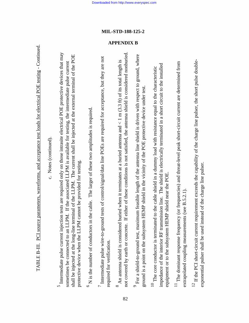
TAB
LE B
-III
. PC
I sou
rce
para
met
ers,
wav
efor
ms,
and
acc
epta
nce
test
load
s fo
r ele
ctric
al P
OE
test
ing
- Con
tinue
d.
c. N
otes
(con
tinue
d).
5 Inte
rmed
iate
pul
se c
urre
nt in
ject
ion
test
s ar
e re
quire
d on
ly o
n th
ose
intra
site
ele
ctric
al P
OE
prot
ectiv
e de
vice
s th
at m
ayso
met
imes
be
conn
ecte
d to
an
LLPM
. If
the
asso
ciat
ed L
LPM
is a
vaila
ble
for t
estin
g, th
e in
term
edia
te p
ulse
cur
rent
shal
l be
inje
cted
at t
he lo
ng-li
ne te
rmin
al o
f the
LLP
M.
The
curr
ent s
hall
be in
ject
ed a
t the
ext
erna
l ter
min
al o
f the
PO
Epr
otec
tive
devi
ce w
hen
the
LLPM
can
not b
e pr
ovid
ed fo
r tes
ting.
6 N is
the
num
ber o
f con
duct
ors
in th
e ca
ble.
The
larg
er o
f the
se tw
o am
plitu
des
is re
quire
d.
7 Inte
rmed
iate
pul
se w
ire-to
-gro
und
test
s of
con
trol/s
igna
l/dat
a lin
e PO
Es a
re re
quire
d fo
r acc
epta
nce,
but
they
are
not
requ
ired
for v
erifi
catio
n.
8 An
ante
nna
shie
ld is
con
side
red
burie
d w
hen
it te
rmin
ates
at a
bur
ied
ante
nna
and
< 1
m (3
.3 ft
) of i
ts to
tal l
engt
h is
not c
over
ed b
y ea
rth o
r con
cret
e. I
f eith
er o
f the
se c
ondi
tions
is n
ot s
atis
fied,
the
ante
nna
shie
ld is
con
side
red
nonb
urie
d.
9 For
a s
hiel
d-to
-gro
und
test
, max
imum
feas
ible
leng
th o
f the
ant
enna
line
shi
eld
is d
riven
with
resp
ect t
o gr
ound
, whe
regr
ound
is a
poi
nt o
n th
e su
bsys
tem
HEM
P sh
ield
in th
e vi
cini
ty o
f the
PO
E pr
otec
tive
devi
ce u
nder
test
.
10 T
he c
ore
cond
ucto
r is
term
inat
ed to
the
cabl
e sh
ield
in a
dum
my
load
with
resi
stan
ce e
qual
to th
e ch
arac
teris
ticim
peda
nce
of th
e in
terio
r RF
trans
mis
sion
line
. Th
e sh
ield
is e
lect
rical
ly te
rmin
ated
in a
sho
rt ci
rcui
t to
the
inst
alle
deq
uipm
ent o
r to
the
subs
yste
m H
EMP
shie
ld n
ear t
he P
OE.
11 T
he d
omin
ant r
espo
nse
freq
uenc
y (o
r fre
quen
cies
) and
thre
at-le
vel p
eak
shor
t-circ
uit c
urre
nt a
re d
eter
min
ed fr
omex
trapo
late
d co
uplin
g m
easu
rem
ents
(see
B.5
.2.1
).
12 If
the
PCI s
hort-
circ
uit c
urre
nt re
quire
men
t exc
eeds
the
capa
bilit
y of
the
char
ge li
ne p
ulse
r, th
e sh
ort p
ulse
dou
ble-
expo
nent
ial p
ulse
r sha
ll be
use
d in
stea
d of
the
char
ge li
ne p
ulse
r.
MIL-STD-188-125-2
APPENDIX B
82
Downloaded from http://www.everyspec.com
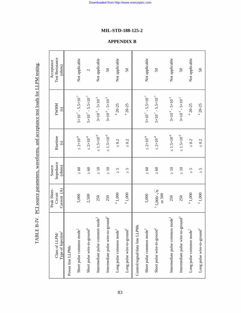
TAB
LE B
-IV
. PC
I sou
rce
para
met
ers,
wav
efor
ms,
and
acc
epta
nce
test
load
s fo
r LLP
M te
stin
g.
Cla
ss o
f LLP
M/
Type
of I
njec
tion1
Peak
Sho
rt-C
ircui
tC
urre
nt (
A)
Sour
ceIm
peda
nce
(ohm
s)R
iset
ime
(s)
FWH
M(s
)
Acc
epta
nce
Test
Res
ista
nce
(ohm
s)
Pow
er li
ne L
LPM
s
Sh
ort p
ulse
com
mon
mod
e25,
000
≥ 60
≤ 2×
10-8
5×10
-7 -
5.5×
10-7
Not
app
licab
le
Sh
ort p
ulse
wire
-to-g
roun
d32,
500
≥ 60
≤ 2×
10-8
5×10
-7 -
5.5×
10-7
2
In
term
edia
te p
ulse
com
mon
mod
e225
0≥
10≤
1.5×
10-6
3×10
-3 -
5×10
-3N
ot a
pplic
able
In
term
edia
te p
ulse
wire
-to-g
roun
d325
0≥
10≤
1.5×
10-6
3×10
-3 -
5×10
-350
Lo
ng p
ulse
com
mon
mod
e24 1
,000
≥ 5
≤ 0.
24 2
0-25
Not
app
licab
le
Lo
ng p
ulse
wire
-to-g
roun
d34 1
,000
≥ 5
≤ 0.
24 2
0-25
50
Con
trol/s
igna
l/dat
a lin
e LL
PMs
Sh
ort p
ulse
com
mon
mod
e25,
000
≥ 60
≤ 2×
10-8
5×10
-7 -
5.5×
10-7
Not
app
licab
le
Sh
ort p
ulse
wire
-to-g
roun
d35 5
,000
/N
or 5
00≥
60≤
2×10
-85×
10-7
- 5.
5×10
-750
In
term
edia
te p
ulse
com
mon
mod
e225
0≥
10≤
1.5×
10-6
3×10
-3 -
5×10
-3N
ot a
pplic
able
In
term
edia
te p
ulse
wire
-to-g
roun
d325
0≥
10≤
1.5×
10-6
3×10
-3 -
5×10
-350
Lo
ng p
ulse
com
mon
mod
e24 1
,000
≥ 5
≤ 0.
24 2
0-25
Not
app
licab
le
Lo
ng p
ulse
wire
-to-g
roun
d34 1
,000
≥ 5
≤ 0.
24 2
0-25
50
83
MIL-STD-188-125-2
APPENDIX B
Downloaded from http://www.everyspec.com
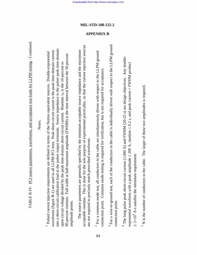
TAB
LE B
-IV
. PC
I sou
rce
para
met
ers,
wav
efor
ms,
and
acc
epta
nce
test
load
s fo
r LLP
M te
stin
g - C
ontin
ued.
Not
es.
1 Pul
sed
curr
ent i
njec
tion
requ
irem
ents
are
def
ined
in te
rms
of th
e N
orto
n eq
uiva
lent
sou
rces
. D
oubl
e-ex
pone
ntia
lw
avef
orm
s (f
igur
e B
-1) a
re u
sed
in a
ll LL
PM P
CI t
ests
. Pe
ak s
hort-
circ
uit c
urre
nt is
the
peak
tim
e-do
mai
n cu
rren
tin
to a
sho
rt-ci
rcui
t cal
ibra
tion
load
at t
he p
ulse
r out
put t
erm
inal
s. S
ourc
e im
peda
nce
is th
e pu
lser
pea
k tim
e-do
mai
nop
en-c
ircui
t vol
tage
div
ided
by
the
peak
tim
e-do
mai
n sh
ort-c
ircui
t cur
rent
. R
iset
ime
τ R is
the
10-p
erce
nt to
90-p
erce
nt ri
setim
e. F
ull-w
idth
at h
alf-
max
imum
am
plitu
de (F
WH
M) i
s th
e tim
e in
terv
al b
etw
een
the
50-p
erce
ntam
plitu
de p
oint
s.
The
sour
ce p
aram
eter
s ar
e ge
nera
lly s
peci
fied
by th
e m
inim
um a
ccep
tabl
e so
urce
impe
danc
e an
d th
e m
axim
umac
cept
able
rise
time.
Thi
s is
don
e fo
r the
sol
e pu
rpos
e of
exp
erim
enta
l pra
ctic
ality
, so
that
the
curr
ent i
njec
tion
sour
ces
are
not r
equi
red
to p
reci
sely
mat
ch p
resc
ribed
wav
efor
ms.
2 For
a c
omm
on m
ode
test
, all
cond
ucto
rs in
the
cabl
e ar
e si
mul
tane
ousl
y dr
iven
with
resp
ect t
o th
e LL
PM g
roun
dco
nnec
tion
poin
t. C
omm
on m
ode
test
ing
is re
quire
d fo
r ver
ifica
tion,
but
is n
ot re
quire
d fo
r acc
epta
nce.
3 Fo
r a w
ire-to
-gro
und
test
, eac
h of
the
cond
ucto
rs in
the
cabl
e is
indi
vidu
ally
driv
en w
ith re
spec
t to
the
LLPM
gro
und
conn
ectio
n po
int.
4 The
long
pul
se p
eak
shor
t-circ
uit c
urre
nt (1
,000
A) a
nd F
WH
M (2
0-25
s) a
re d
esig
n ob
ject
ives
. A
ny d
oubl
e-ex
pone
ntia
l wav
efor
m w
ith a
pea
k am
plitu
de ≥
200
A, r
iset
ime
≤ 0.
2 s,
and
pea
k cu
rren
t × F
WH
M p
rodu
ct≥
2×10
4 A-s
sat
isfie
s th
e m
inim
um re
quire
men
t.
5 N is
the
num
ber o
f con
duct
ors
in th
e ca
ble.
The
larg
er o
f the
se tw
o am
plitu
des
is re
quire
d.
MIL-STD-188-125-2
APPENDIX B
84
Downloaded from http://www.everyspec.com
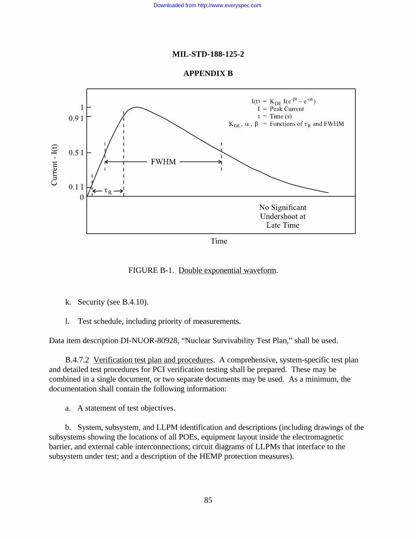
MIL-STD-188-125-2
APPENDIX B
85
k. Security (see B.4.10).
l. Test schedule, including priority of measurements.
Data item description DI-NUOR-80928, “Nuclear Survivability Test Plan,” shall be used.
B.4.7.2 Verification test plan and procedures. A comprehensive, system-specific test planand detailed test procedures for PCI verification testing shall be prepared. These may becombined in a single document, or two separate documents may be used. As a minimum, thedocumentation shall contain the following information:
a. A statement of test objectives.
b. System, subsystem, and LLPM identification and descriptions (including drawings of thesubsystems showing the locations of all POEs, equipment layout inside the electromagneticbarrier, and external cable interconnections; circuit diagrams of LLPMs that interface to thesubsystem under test; and a description of the HEMP protection measures).
FIGURE B-1. Double exponential waveform.
Downloaded from http://www.everyspec.com
MIL-STD-188-125-2
APPENDIX B
86
c. Identification of the circuits and protective devices to be tested (including circuitfunctions and manufacturers’ data sheets and specifications for the protective devices).
d. HEMP simulation and data acquisition equipment descriptions (including manufacturer,model and serial numbers, characteristics, and detailed calibration procedures).
e. Identification of POE protective device injection points, injection levels and waveforms(see table B-III), and measurement points.
f. Identification of LLPM injection points, injection levels and waveforms (see table B-IV),and measurement points.
g. Detailed test procedures.
h. Any deviations from the requirements of this Appendix.
i. Data management (including data quality control procedures, data acceptability criteria,annotation and preservation of data records, and pass/fail criteria).
j. Safety, including electromagnetic radiation and electrical shock hazards.
k. Security (see B.4.10).
l. Test schedule, including priority of measurements.
Data item description DI-NUOR-80928, “Nuclear Survivability Test Plan,” shall be used.
B.4.8 Test report requirements.
B.4.8.1 Acceptance test report. A PCI acceptance test report shall be prepared. As aminimum, the report shall contain the following information:
a. System identification and a reference to the applicable test plan. b. A discussion of any deviations from the test plan or the requirements of this Appendix.
c. Copies of the measured results, along with sensor calibrations and instrumentationsettings required to convert the data to engineering units. If the data are collected and processedwith an automated data acquisition system and a complete set of data will be delivered inelectronic format, samples of the processed data may be provided in the report.
Downloaded from http://www.everyspec.com
MIL-STD-188-125-2
APPENDIX B
87
d. A summary table of the norms of the measured residual internal transient stresses, withcomparisons to the maximum allowable residual response characteristics (see tables B-V andB-VI).
e. Pass/fail conclusions.
Data item description DI-NUOR-80929A, “Nuclear Survivability Test Report,” shall be used.
B.4.8.2 Verification test report. A PCI verification test report shall be prepared. As aminimum, the report shall contain the following information:
a. System identification and a reference to the applicable test plan.
b. A discussion of any deviations from the test plan or the requirements of this Appendix.
c. Copies of the measured results, along with sensor calibrations and instrumentationsettings required to convert the data to engineering units. If the data are collected and processedwith an automated data acquisition system and a complete set of data will be delivered inelectronic format, samples of the processed data may be provided in the report.
d. A summary table of the norms of the measured residual internal transient stresses, withcomparisons to the maximum allowable residual response characteristics (see tables B-V andB-VI).
e. Test chronology (including a sequence of events; identification of failures, upsets, orinterference observed and the conditions under which they occurred; findings from investigationinto the causes of test failures, if any; and corrective actions and retest results).
f. Test conclusions including a definitive statement of the HEMP hardness of the systemand subsystem mission functions, based on the results of the complete battery of verification testsand the supporting analysis.
Data item description DI-NUOR-80929A, “Nuclear Survivability Test Report,” shall be used.
Downloaded from http://www.everyspec.com
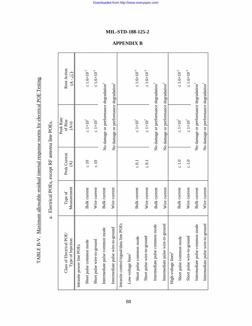
TAB
LE B
-V.
Max
imum
allo
wab
le re
sidu
al in
tern
al re
spon
se n
orm
s fo
r ele
ctric
al P
OE
Test
ing.
a. E
lect
rical
PO
Es, e
xcep
t RF
ante
nna
line
POEs
.
Cla
ss o
f Ele
ctric
al P
OE/
Type
of I
njec
tion
Type
of
Mea
sure
men
tPe
ak C
urre
nt(A
)
Peak
Rat
e o
f Ris
e(A
/s)
Roo
t Act
ion
(A -
s)In
trasi
te p
ower
line
PO
Es
Sh
ort p
ulse
com
mon
mod
eB
ulk
curr
ent
≤ 10
≤ 1×
107
≤ 1.
6×10
-1
Sh
ort p
ulse
wire
-to-g
roun
dW
ire c
urre
nt≤
10≤
1×10
7≤
1.6×
10-1
In
term
edia
te p
ulse
com
mon
mod
eB
ulk
curr
ent
No
dam
age
or p
erfo
rman
ce d
egra
datio
n1
In
term
edia
te p
ulse
wire
-to-g
roun
dW
ire c
urre
ntN
o da
mag
e or
per
form
ance
deg
rada
tion1
Intra
site
con
trol/s
igna
l/dat
a lin
e PO
Es
Lo
w-v
olta
ge li
nes2
Shor
t pul
se c
omm
on m
ode
Bul
k cu
rren
t≤
0.1
≤ 1×
107
≤ 1.
6×10
-3
Shor
t pul
se w
ire-to
-gro
und
Wire
cur
rent
≤ 0.
1≤
1×10
7≤
1.6×
10-3
Inte
rmed
iate
pul
se c
omm
on m
ode
Bul
k cu
rren
tN
o da
mag
e or
per
form
ance
deg
rada
tion1
Inte
rmed
iate
pul
se w
ire-to
-gro
und
Wire
cur
rent
No
dam
age
or p
erfo
rman
ce d
egra
datio
n1
H
igh-
volta
ge li
nes2
Shor
t pul
se c
omm
on m
ode
Bul
k cu
rren
t≤
1.0
≤ 1×
107
≤ 1.
6×10
-2
Shor
t pul
se w
ire-to
-gro
und
Wire
cur
rent
≤ 1.
0≤
1×10
7≤
1.6×
10-2
Inte
rmed
iate
pul
se c
omm
on m
ode
Bul
k cu
rren
tN
o da
mag
e or
per
form
ance
deg
rada
tion1
Inte
rmed
iate
pul
se w
ire-to
-gro
und
Wire
cur
rent
No
dam
age
or p
erfo
rman
ce d
egra
datio
n1
MIL-STD-188-125-2
APPENDIX B
88
Downloaded from http://www.everyspec.com
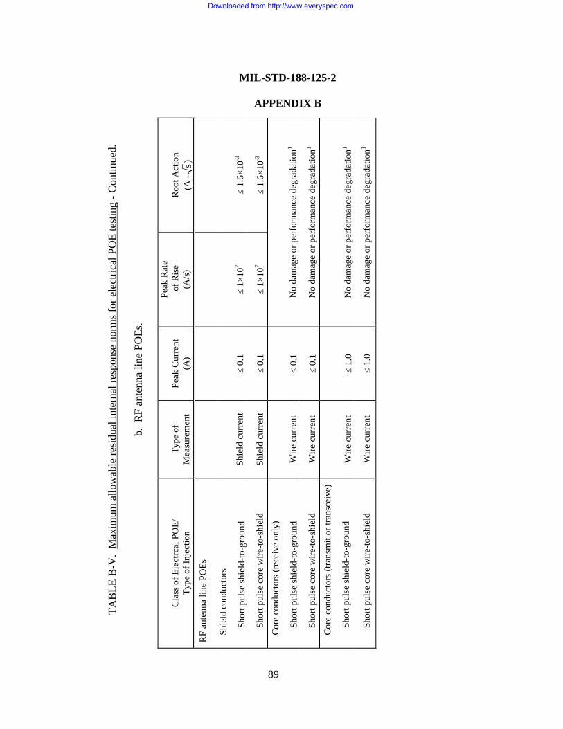
TAB
LE B
-V.
Max
imum
allo
wab
le re
sidu
al in
tern
al re
spon
se n
orm
s fo
r ele
ctric
al P
OE
test
ing
- Con
tinue
d.
b. R
F an
tenn
a lin
e PO
Es.
Cla
ss o
f Ele
ctrc
al P
OE/
Type
of I
njec
tion
Type
of
Mea
sure
men
tPe
ak C
urre
nt(A
)
Peak
Rat
e o
f Ris
e(A
/s)
Roo
t Act
ion
(A -
s)R
F an
tenn
a lin
e PO
Es
Sh
ield
con
duct
ors
Shor
t pul
se s
hiel
d-to
-gro
und
Shie
ld c
urre
nt≤
0.1
≤ 1×
107
≤ 1.
6×10
-3
Shor
t pul
se c
ore
wire
-to-s
hiel
dSh
ield
cur
rent
≤ 0.
1≤
1×10
7≤
1.6×
10-3
C
ore
cond
ucto
rs (r
ecei
ve o
nly)
Shor
t pul
se s
hiel
d-to
-gro
und
Wire
cur
rent
≤ 0.
1N
o da
mag
e or
per
form
ance
deg
rada
tion1
Shor
t pul
se c
ore
wire
-to-s
hiel
dW
ire c
urre
nt≤
0.1
No
dam
age
or p
erfo
rman
ce d
egra
datio
n1
C
ore
cond
ucto
rs (t
rans
mit
or tr
ansc
eive
)
Shor
t pul
se s
hiel
d-to
-gro
und
Wire
cur
rent
≤ 1.
0N
o da
mag
e or
per
form
ance
deg
rada
tion1
Shor
t pul
se c
ore
wire
-to-s
hiel
dW
ire c
urre
nt≤
1.0
No
dam
age
or p
erfo
rman
ce d
egra
datio
n1
89
MIL-STD-188-125-2
APPENDIX B
Downloaded from http://www.everyspec.com
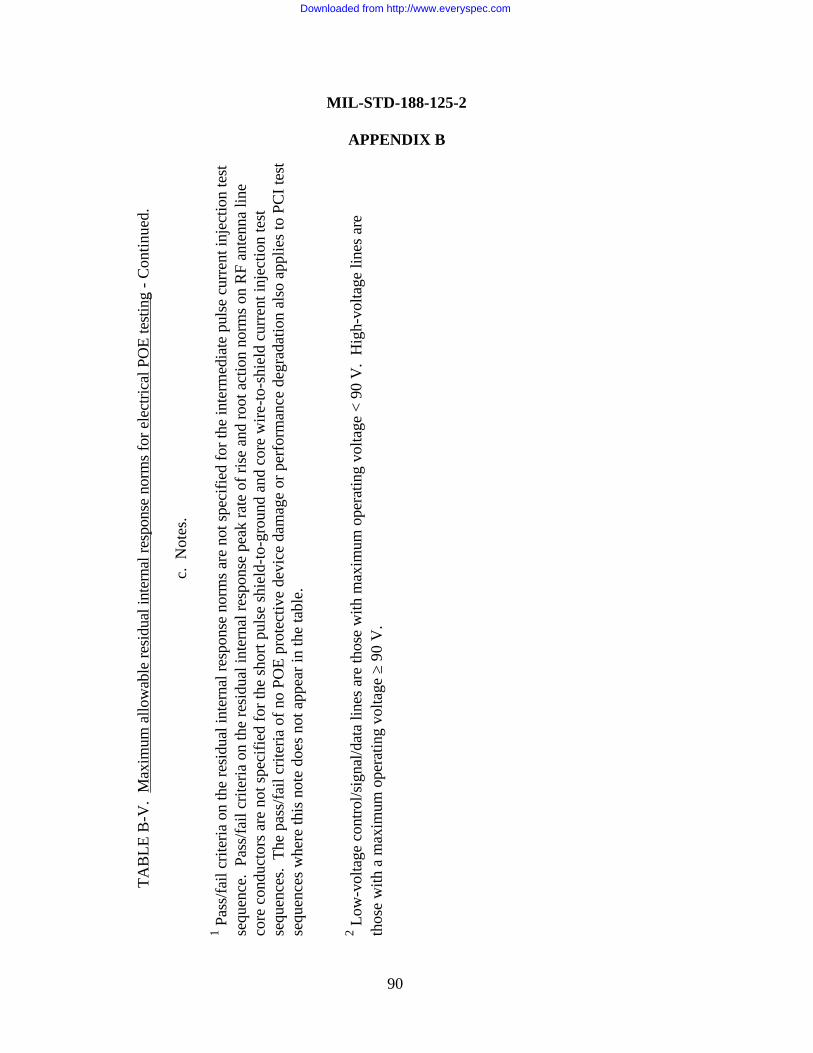
TAB
LE B
-V.
Max
imum
allo
wab
le re
sidu
al in
tern
al re
spon
se n
orm
s fo
r ele
ctric
al P
OE
test
ing
- Con
tinue
d.
c. N
otes
.
1 Pas
s/fa
il cr
iteria
on
the
resi
dual
inte
rnal
resp
onse
nor
ms
are
not s
peci
fied
for t
he in
term
edia
te p
ulse
cur
rent
inje
ctio
n te
stse
quen
ce.
Pass
/fail
crite
ria o
n th
e re
sidu
al in
tern
al re
spon
se p
eak
rate
of r
ise
and
root
act
ion
norm
s on
RF
ante
nna
line
core
con
duct
ors
are
not s
peci
fied
for t
he s
hort
puls
e sh
ield
-to-g
roun
d an
d co
re w
ire-to
-shi
eld
curr
ent i
njec
tion
test
sequ
ence
s. T
he p
ass/
fail
crite
ria o
f no
POE
prot
ectiv
e de
vice
dam
age
or p
erfo
rman
ce d
egra
datio
n al
so a
pplie
s to
PC
I tes
tse
quen
ces
whe
re th
is n
ote
does
not
app
ear i
n th
e ta
ble.
2 Low
-vol
tage
con
trol/s
igna
l/dat
a lin
es a
re th
ose
with
max
imum
ope
ratin
g vo
ltage
< 9
0 V
. H
igh-
volta
ge li
nes
are
thos
e w
ith a
max
imum
ope
ratin
g vo
ltage
≥ 9
0 V
.
MIL-STD-188-125-2
APPENDIX B
90
Downloaded from http://www.everyspec.com
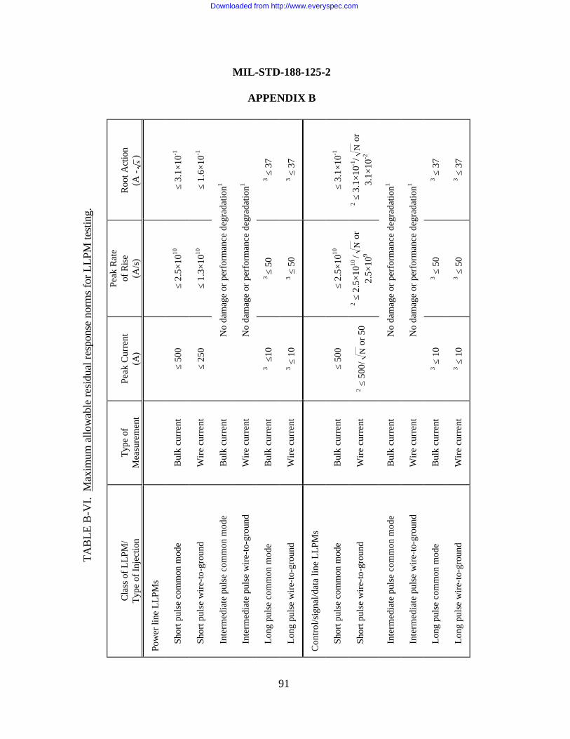
TAB
LE B
-VI.
Max
imum
allo
wab
le re
sidu
al re
spon
se n
orm
s fo
r LLP
M te
stin
g.
Cla
ss o
f LLP
M/
Type
of I
njec
tion
Type
of
Mea
sure
men
tPe
ak C
urre
nt(A
)
Peak
Rat
eof
Ris
e(A
/s)
Roo
t Act
ion
(A -
s)
Pow
er li
ne L
LPM
s
Sh
ort p
ulse
com
mon
mod
eB
ulk
curr
ent
≤ 50
0≤
2.5×
1010
≤ 3.
1×10
-1
Sh
ort p
ulse
wire
-to-g
roun
dW
ire c
urre
nt≤
250
≤ 1.
3×10
10≤
1.6×
10-1
In
term
edia
te p
ulse
com
mon
mod
eB
ulk
curr
ent
No
dam
age
or p
erfo
rman
ce d
egra
datio
n1
In
term
edia
te p
ulse
wire
-to-g
roun
dW
ire c
urre
ntN
o da
mag
e or
per
form
ance
deg
rada
tion1
Lo
ng p
ulse
com
mon
mod
eB
ulk
curr
ent
3 ≤10
3 ≤
503 ≤
37
Lo
ng p
ulse
wire
-to-g
roun
dW
ire c
urre
nt3 ≤
10
3 ≤ 5
03 ≤
37
Con
trol/s
igna
l/dat
a lin
e LL
PMs
Sh
ort p
ulse
com
mon
mod
eB
ulk
curr
ent
≤ 50
0≤
2.5×
1010
≤ 3.
1×10
-1
Sh
ort p
ulse
wire
-to-g
roun
dW
ire c
urre
nt2 ≤
500
/N
or 5
02 ≤
2.5
×1010
/N
or2.
5×10
9
2 ≤ 3
.1×1
0-1/
Nor
3.1×
10-2
In
term
edia
te p
ulse
com
mon
mod
eB
ulk
curr
ent
No
dam
age
or p
erfo
rman
ce d
egra
datio
n1
In
term
edia
te p
ulse
wire
-to-g
roun
dW
ire c
urre
ntN
o da
mag
e or
per
form
ance
deg
rada
tion1
Lo
ng p
ulse
com
mon
mod
eB
ulk
curr
ent
3 ≤ 1
03 ≤
50
3 ≤ 3
7
Lo
ng p
ulse
wire
-to-g
roun
dW
ire c
urre
nt3 ≤
10
3 ≤ 5
03 ≤
37
MIL-STD-188-125-2
APPENDIX B
91
Downloaded from http://www.everyspec.com
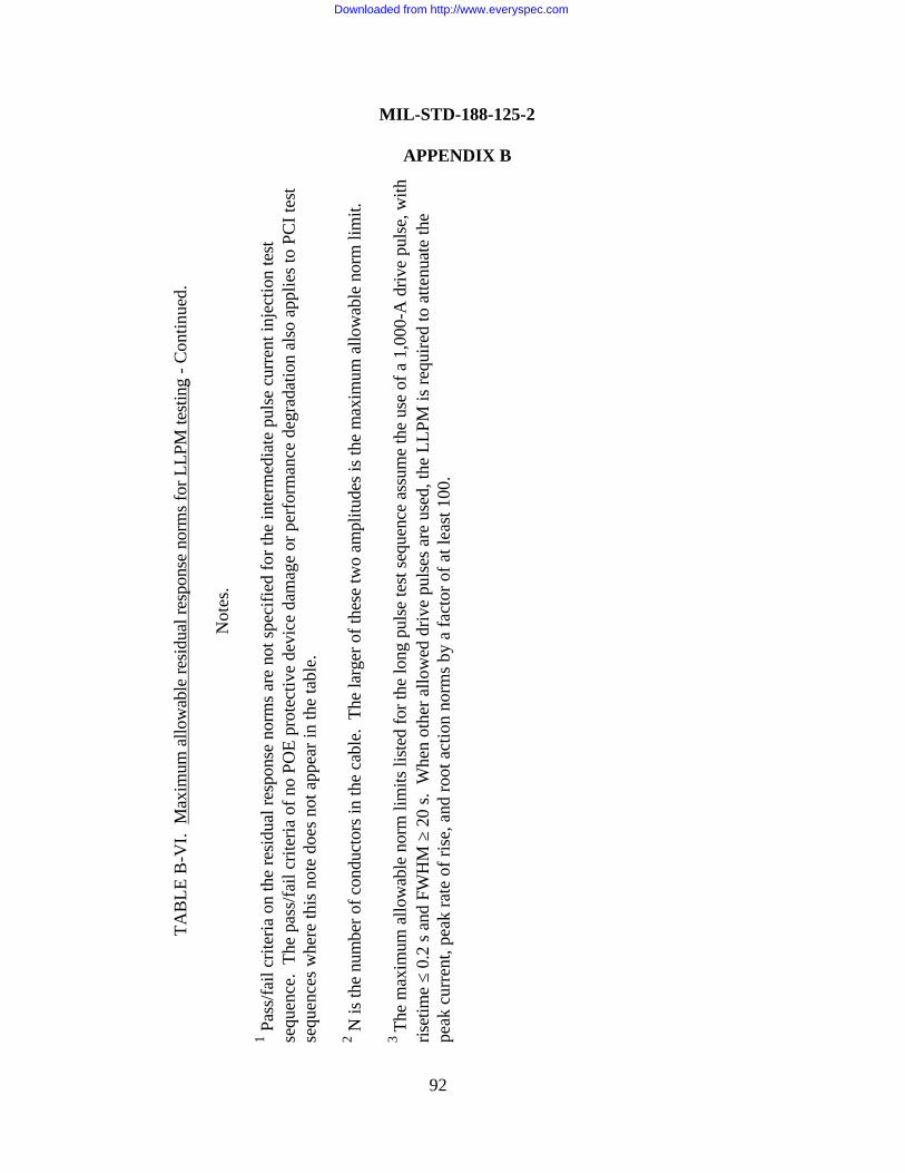
TAB
LE B
-VI.
Max
imum
allo
wab
le re
sidu
al re
spon
se n
orm
s fo
r LLP
M te
stin
g - C
ontin
ued.
Not
es.
1 Pas
s/fa
il cr
iteria
on
the
resi
dual
resp
onse
nor
ms
are
not s
peci
fied
for t
he in
term
edia
te p
ulse
cur
rent
inje
ctio
n te
stse
quen
ce.
The
pass
/fail
crite
ria o
f no
POE
prot
ectiv
e de
vice
dam
age
or p
erfo
rman
ce d
egra
datio
n al
so a
pplie
s to
PC
I tes
tse
quen
ces
whe
re th
is n
ote
does
not
app
ear i
n th
e ta
ble.
2 N is
the
num
ber o
f con
duct
ors
in th
e ca
ble.
The
larg
er o
f the
se tw
o am
plitu
des
is th
e m
axim
um a
llow
able
nor
m li
mit.
3 Th
e m
axim
um a
llow
able
nor
m li
mits
list
ed fo
r the
long
pul
se te
st s
eque
nce
assu
me
the
use
of a
1,0
00-A
driv
e pu
lse,
with
riset
ime
≤ 0.
2 s
and
FWH
M ≥
20
s. W
hen
othe
r allo
wed
driv
e pu
lses
are
use
d, th
e LL
PM is
requ
ired
to a
ttenu
ate
the
peak
cur
rent
, pea
k ra
te o
f ris
e, a
nd ro
ot a
ctio
n no
rms
by a
fact
or o
f at l
east
100
.
MIL-STD-188-125-2
APPENDIX B
92
Downloaded from http://www.everyspec.com
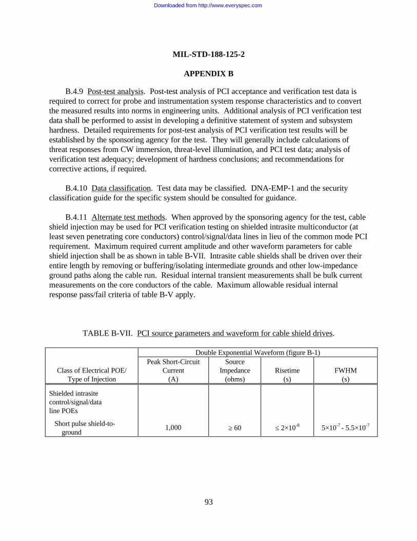
MIL-STD-188-125-2
APPENDIX B
93
B.4.9 Post-test analysis. Post-test analysis of PCI acceptance and verification test data isrequired to correct for probe and instrumentation system response characteristics and to convertthe measured results into norms in engineering units. Additional analysis of PCI verification testdata shall be performed to assist in developing a definitive statement of system and subsystemhardness. Detailed requirements for post-test analysis of PCI verification test results will beestablished by the sponsoring agency for the test. They will generally include calculations ofthreat responses from CW immersion, threat-level illumination, and PCI test data; analysis ofverification test adequacy; development of hardness conclusions; and recommendations forcorrective actions, if required.
B.4.10 Data classification. Test data may be classified. DNA-EMP-1 and the securityclassification guide for the specific system should be consulted for guidance.
B.4.11 Alternate test methods. When approved by the sponsoring agency for the test, cableshield injection may be used for PCI verification testing on shielded intrasite multiconductor (atleast seven penetrating core conductors) control/signal/data lines in lieu of the common mode PCIrequirement. Maximum required current amplitude and other waveform parameters for cableshield injection shall be as shown in table B-VII. Intrasite cable shields shall be driven over theirentire length by removing or buffering/isolating intermediate grounds and other low-impedanceground paths along the cable run. Residual internal transient measurements shall be bulk currentmeasurements on the core conductors of the cable. Maximum allowable residual internalresponse pass/fail criteria of table B-V apply.
TABLE B-VII. PCI source parameters and waveform for cable shield drives.
Double Exponential Waveform (figure B-1)
Class of Electrical POE/Type of Injection
Peak Short-CircuitCurrent
(A)
SourceImpedance
(ohms)Risetime
(s)FWHM
(s)
Shielded intrasitecontrol/signal/dataline POEs
Short pulse shield-to- ground
1,000 ≥ 60 ≤ 2×10⁻⁸ 5×10⁻⁷ - 5.5×10⁻⁷
Downloaded from http://www.everyspec.com
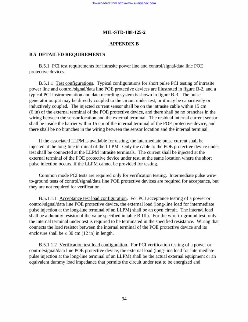
MIL-STD-188-125-2
APPENDIX B
94
B.5 DETAILED REQUIREMENTS
B.5.1 PCI test requirements for intrasite power line and control/signal/data line POEprotective devices.
B.5.1.1 Test configurations. Typical configurations for short pulse PCI testing of intrasitepower line and control/signal/data line POE protective devices are illustrated in figure B-2, and atypical PCI instrumentation and data recording system is shown in figure B-3. The pulsegenerator output may be directly coupled to the circuit under test, or it may be capacitively orinductively coupled. The injected current sensor shall be on the intrasite cable within 15 cm(6 in) of the external terminal of the POE protective device, and there shall be no branches in thewiring between the sensor location and the external terminal. The residual internal current sensorshall be inside the barrier within 15 cm of the internal terminal of the POE protective device, andthere shall be no branches in the wiring between the sensor location and the internal terminal.
If the associated LLPM is available for testing, the intermediate pulse current shall beinjected at the long-line terminal of the LLPM. Only the cable to the POE protective device undertest shall be connected at the LLPM intrasite terminals. The current shall be injected at theexternal terminal of the POE protective device under test, at the same location where the shortpulse injection occurs, if the LLPM cannot be provided for testing.
Common mode PCI tests are required only for verification testing. Intermediate pulse wire-to-ground tests of control/signal/data line POE protective devices are required for acceptance, butthey are not required for verification.
B.5.1.1.1 Acceptance test load configuration. For PCI acceptance testing of a power orcontrol/signal/data line POE protective device, the external load (long-line load for intermediatepulse injection at the long-line terminal of an LLPM) shall be an open circuit. The internal loadshall be a dummy resistor of the value specified in table B-IIIa. For the wire-to-ground test, onlythe internal terminal under test is required to be terminated in the specified resistance. Wiring thatconnects the load resistor between the internal terminal of the POE protective device and itsenclosure shall be ≤ 30 cm (12 in) in length.
B.5.1.1.2 Verification test load configuration. For PCI verification testing of a power orcontrol/signal/data line POE protective device, the external load (long-line load for intermediatepulse injection at the long-line terminal of an LLPM) shall be the actual external equipment or anequivalent dummy load impedance that permits the circuit under test to be energized and
Downloaded from http://www.everyspec.com
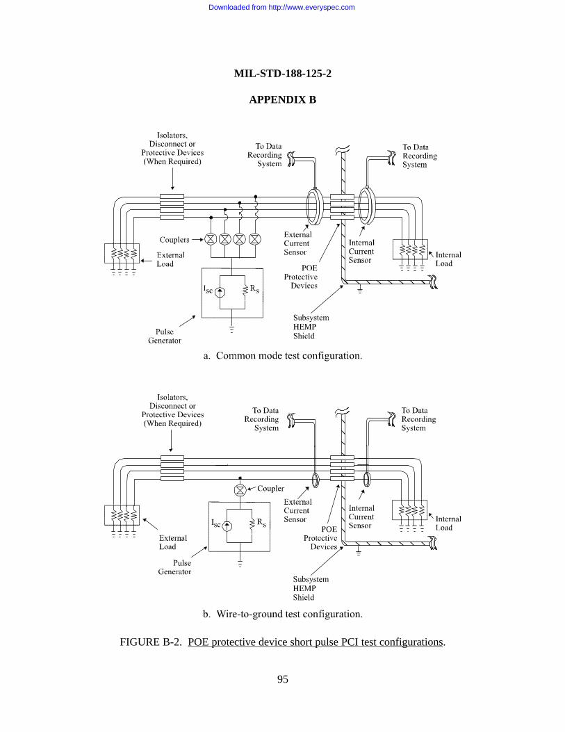
MIL-STD-188-125-2
APPENDIX B
95
FIGURE B-2. POE protective device short pulse PCI test configurations.
Downloaded from http://www.everyspec.com
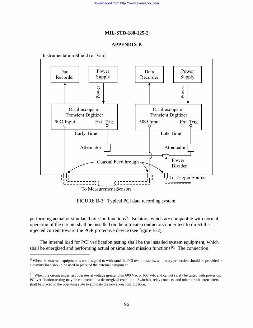
MIL-STD-188-125-2
APPENDIX B
96
FIGURE B-3. Typical PCI data recording system.
performing actual or simulated mission functions9. Isolators, which are compatible with normaloperation of the circuit, shall be installed on the intrasite conductors under test to direct theinjected current toward the POE protective device (see figure B-2).
The internal load for PCI verification testing shall be the installed system equipment, whichshall be energized and performing actual or simulated mission functions10. The connection 9 When the external equipment is not designed to withstand the PCI test transients, temporary protection should be provided ora dummy load should be used in place of the external equipment.
10 When the circuit under test operates at voltage greater than 600 Vac or 600 Vdc and cannot safely be tested with power on,PCI verification testing may be conducted in a deenergized condition. Switches, relay contacts, and other circuit interruptersshall be placed in the operating state to simulate the power-on configuration.
Downloaded from http://www.everyspec.com
MIL-STD-188-125-2
APPENDIX B
97
between the internal terminal of the POE protective device and the load equipment shall be madeusing the installed system cabling.
B.5.1.2 Pulse generator requirements. Maximum short-circuit current amplitude, waveform,and source impedance requirements of the double-exponential short pulse and intermediate pulsegenerators required for PCI acceptance and verification testing of intrasite power line andcontrol/signal/data line POE protective devices shall be as shown in table B-IIIa and figure B-1.
B.5.1.3 Test sequence. To minimize the possibility of POE protective device or equipmentdamage, a series of pulses at increasing amplitudes shall be applied as follows:
a. Pulse at the lowest available output from the pulse generator. This level shall be ≤ 10percent of the applicable maximum amplitude in table B-IIIa or less than the amplitude thatactivates any nonlinear components in the POE protective device, whichever is greater.
b. Perform a series of pulses, increasing the amplitude by a factor of approximately two ateach step. When testing multiple circuits with identical POE protective devices, this series ofintermediate pulses may be abbreviated after the first two samples.
c. Pulse at the maximum required amplitude for the circuit under test. Peak current shouldnot exceed 110 percent of the maximum level listed in table B-IIIa.
This sequence shall be used for both PCI acceptance and PCI verification testing.
CAUTION: Electrical POE protective devices have limited pulse lives. The number of testpulses delivered to each device, peak currents, and pulse widths should be recorded for inclusionin maintenance records. If the total number of previous pulses on a device exceed 90 percent ofthe rated life, it should be replaced before starting the test.
B.5.2 PCI test requirements for RF antenna line POE protective devices. The HEMPprotection for an RF antenna installation and the POE protective device at the antenna linepenetration through a subsystem electromagnetic barrier shall be tested in accordance with thegeneral procedure for special protective measures. The test sequence shall include couplingmeasurements on the antenna installation; PCI testing at the antenna terminals; PCI testing on theantenna line shield; and PCI testing of the protected MCE, when required.
Downloaded from http://www.everyspec.com
MIL-STD-188-125-2
APPENDIX B
98
B.5.2.1 Coupling measurements. Coupling measurements shall be made on the completeantenna installation (figure B-4) that includes the antenna; antenna protective device, if provided;antenna-mounted electronics and tuning circuits outside the electromagnetic barrier, if provided;the external RF transmission line; and the electrical POE protective device (or primary andsecondary electrical POE protective devices, if the protected interior equipment is within a specialprotective barrier). The antenna line core conductor shall be terminated inside theelectromagnetic barrier into a dummy resistor, with resistance equal to the interior transmissionline characteristic impedance, for acceptance testing. The core conductor shall be terminated intothe installed system equipment, which shall be energized and performing actual or simulatedmission functions, for verification testing. The shield conductor shall be connected to the installedequipment or to the HEMP shield for both test sequences. If the complete antenna installation isnot available at the time of system acceptance from the contractor, acceptance testing shall bedeferred until the complete installation becomes available.
Excitation for the coupling measurements may be supplied by CW immersion, threat-levelillumination, subthreat transient field illumination, or another threat-relatable method. To theextent practical, the locations and polarizations of the transmitting antennas shall be chosen tomaximize the antenna response. Measurements of the current coupled to the signal-carrying coreconductor shall be made at the antenna terminals and on the protected side of the barrier POEprotective device (or primary and secondary special POE protective devices). Couplingmeasurements on antenna installations with tuning circuits outside the electromagnetic barriershall be made at the lowest operating frequency, a midband operating frequency, and the highestoperating frequency.
Coupling measurements shall be extrapolated to the upper-bound HEMP-induced responsesfor the MIL-STD-2169 threat environment, assuming linear behavior of the antenna installationand its HEMP protection measures. The extrapolation shall include a factor of 10 to account foruncontrollable coupling parameters, such as incident field departure from planarity and groundconductivity, and other uncertainties present in the coupling test (see MIL-HDBK-423), unless asmaller correction factor can be justified in the analysis. The peak time-domain amplitude of theantenna upper-bound response and dominant response frequency (or frequencies), indicated by asignificant peak in the current response spectrum per unit incident field versus frequency curve,shall be determined. The threat-extrapolated peak amplitude of the residual internal responsecurrent shall also be determined.
It is not necessary to repeat the coupling measurements during the verification test programif the configuration of the antenna installation and equipment in its vicinity has not changedbetween acceptance and verification testing. PCI verification injection levels shall be determinedfrom the extrapolated acceptance coupling measurements, when new coupling measurements arenot required.
Downloaded from http://www.everyspec.com
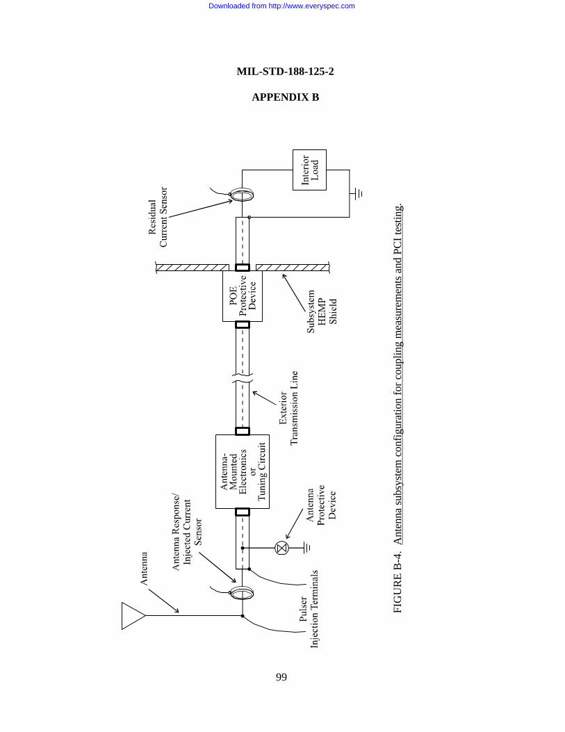
FIG
UR
E B
-4.
Ant
enna
sub
syst
em c
onfig
urat
ion
for c
oupl
ing
mea
sure
men
ts a
nd P
CI t
estin
g.
99
MIL-STD-188-125-2
APPENDIX B
Downloaded from http://www.everyspec.com
MIL-STD-188-125-2
APPENDIX B
100
B.5.2.2 Antenna terminal PCI test. PCI testing on an RF antenna line core conductor shallbe performed on the complete antenna installation, using injections at the antenna terminals. Anantenna with tuning circuits outside the electromagnetic barrier shall be PCI tested at the lowestoperating frequency, the midband operating frequency at which coupling measurements wereacquired, and the highest operating frequency. An antenna subsystem with multiple dominantresponse frequencies shall be tested at all such frequencies.
Maximum short-circuit current amplitude, waveform, and source impedance requirements ofthe pulse generators required for PCI acceptance and verification testing of RF antennainstallation and antenna line POE protective devices shall be as shown in table B-IIIb. Thedouble-exponential short pulse generator shall be used for testing at dominant responsefrequencies ≤ 30 MHz. The charge line pulser, with the length of the charge line adjusted to thequarter-wavelength of the applicable frequency, shall be used for testing at dominant responsefrequencies > 30 MHz. If the required injection level at a dominant response frequency > 30MHz exceeds the capability of the charge line pulser, the double-exponential short pulse generatorshall be employed. The highest required current injection level shall be that supplied at the pulsercharge voltage that produces two times the upper-bound antenna terminal response into a short-circuit calibration load.
Injections shall be sequentially performed at approximately 10 percent, 25 percent, 50percent, and 100 percent of the highest required level. Injected current and residual internalcurrent waveforms shall be recorded, and peak levels shall be graphed versus pulser chargevoltage. Additional pulses shall the be applied at pulser charge voltages where the responses arenonlinear functions of the voltage. These additional shots ensure that the largest pulser-producedpeak residual current, which may not occur at the highest injection level, is recorded.
B.5.2.3 Antenna line shield PCI test. Maximum short-circuit current amplitude, waveform,and source impedance requirements of the double-exponential short pulse generator required forPCI acceptance and verification testing of RF antenna line shields shall be as shown in table B-IIIb. For PCI acceptance testing, the interior load on the core conductor shall be a dummyresistor with resistance equal to the characteristic impedance of the interior transmission line. Theshield shall be connected to the installed equipment or the subsystem HEMP shield. Forverification testing, the core conductor and shield shall terminated normally into the installedequipment.
The maximum feasible length of the exterior antenna line shield shall be driven by removingor buffering/isolating intermediate grounds and other low-impedance ground paths along the run.The test sequence shall be the same as that prescribed for testing other electrical POE protectivedevices (see B.5.1.3).
Downloaded from http://www.everyspec.com
MIL-STD-188-125-2
APPENDIX B
101
B.5.2.4 Internal equipment test. If the norms of the residual internal transient currentmeasured in the antenna terminal PCI test exceed the applicable maximum allowable limits (seetable B-Vb), a special protective volume shall be established to enclose the wiring and equipmentdirectly connected to the POE protective device. Verification testing of the special protectivebarrier and the MCE in the special protective volume is then required.
B.5.3 PCI test requirements for LLPMs.
B.5.3.1 Test configurations. LLPM PCI test configurations are similar those previouslyshown in figure B-2. Again, the pulse generator output may be directly coupled to the circuitunder test, or it may be capacitively or inductively coupled. The injected current sensor shall beon the long-line side within 15 cm (6 in) of its connection point at the LLPM, and there shall beno branches in the wiring between the sensor location and the long-line LLPM connection point.The residual current sensor shall be on the intrasite line side within 15 cm of its connection pointat the LLPM, and there shall be no branches in the wiring between the sensor location and theintrasite cable LLPM connection point.
B.5.3.1.1 Acceptance test load configuration. For PCI acceptance testing of an LLPM, theload on the long-line side shall be an open circuit and the load on the intrasite cable side shall be adummy resistor of the value specified in table B-IV. For the wire-to-ground test, only theintrasite cable connection point under test is required to be terminated in the specified resistance.Wiring that connects the load resistor between the intrasite cable connection point and the LLPMground connection shall have the minimum practical length.
B.5.3.1.2 Verification test load configuration. For PCI verification of an LLPM, the long-line load shall be the equipment to which the line normally connects or an equivalent dummy loadimpedance that permits the circuit under test to be energized and operational9,10. Isolators, whichare compatible with normal operation of the circuit, shall be installed on the long-line wires undertest to direct the injected current toward the LLPM. The intrasite line shall be connected to theLLPM and to the system element (or elements) to which it normally interfaces with the systemcables that are used during normal system deployments. All mission-critical subsystems andequipment connected to the LLPM under test shall be energized and performing actual orsimulated mission functions.
B.5.3.2 Pulse generator requirements. Maximum short-circuit current amplitude, waveform,and source impedance requirements of the short pulse, intermediate pulse, and long pulsegenerators required for PCI acceptance and verification testing of LLPMs shall be as shown intable B-IV and figure B-1. Common mode PCI tests are required only for verification testing.
Downloaded from http://www.everyspec.com
MIL-STD-188-125-2
APPENDIX B
102
B.5.3.3 Test sequence. To minimize the possibility of LLPM or system damage, a series ofpulses at increasing amplitudes shall be applied. The first pulse shall be at the lowest availableoutput from the pulse generator. This level shall be ≤ 10 percent of the applicable maximumamplitude in table B-IV or less than the amplitude that activates any nonlinear components in theLLPM, whichever is greater. A series of pulses, increasing the amplitude by a factor ofapproximately two at each step, shall then be performed. Finally, a pulse at the maximumrequired amplitude for the LLPM under test shall be injected. Peak current should not exceed110 percent of the maximum level listed in table B-IV. This sequence shall be used for both PCIacceptance and PCI verification testing.
B.5.4 Measurements and functional observations.
B.5.4.1 Data requirements. At each step in the testing sequence, both for acceptance andverification testing, the injected pulse amplitude and waveform and the residual responseamplitude and waveform shall be recorded11. The residual response waveforms for short pulsetests shall be recorded for 5 ms after the start of the PCI drive pulse, with recording instrumentsweep speeds that allow resolution of the early-, intermediate-, and late-time responses. Theresidual response waveforms for intermediate pulse tests shall be recorded for 50 ms after thestart of the PCI drive pulse. The residual response waveforms for long pulse tests shall berecorded for approximately 100 seconds after the start of the PCI drive pulse.
B.5.4.2 Verification test functional observations. Operation of the system MCE shall bemonitored during and immediately after each PCI verification test pulse for indications of damageor upset. A detailed description of each abnormal occurrence, along with information concerningthe test and operational conditions under which the occurrence was observed, shall be included inthe test chronology. A determination whether the observed abnormal occurrence is mission-aborting will be made by the operational authority for the system.
B.5.4.3 Measurement procedures. PCI test procedures for acceptance and verificationtesting shall be as follows:
a. Set up the pulse generator sources and data acquisition system in the desiredconfiguration, and perform calibrations.
11 When a POE protective device under test leads into a special protective volume inside a subsystem electromagnetic barrier,amplitudes and waveforms shall also be recorded on all electrical POEs through the special protective barrier into the protectedvolume. The measurements shall be made in the protected volume. Pass/fail criteria for these data are the same as thepass/fail criteria for other internal response measurements.
Downloaded from http://www.everyspec.com
MIL-STD-188-125-2
APPENDIX B
103
b. Deenergize the POE protective device or LLPM circuit to be tested for acceptancetesting and when required by safety considerations. Install sensors and pulse generatorconnections. Reenergize the circuit after sensor installation is complete (verification testing only).
c. Perform a noise check of the instrumentation and data recording system to ensure that asatisfactory signal-to-noise ratio exists.
d. Establish the required system, subsystem, equipment state, and test configurations.
e. Inject a current pulse into the circuit under test, as required by the test sequence (seeB.5.1.3, B.5.2.2, B.5.2.3, or B.5.3.3), and record the injected pulse waveform.
f. Record the response waveforms at the measurement points. Record the results from thefunctional monitoring of the MCE (verification testing only).
g. Compare the measured results and functional observations (verification testing only) tothe pass/fail criteria (see B.5.5). If the results are not satisfactory, halt the test and investigate thecause of the failure. Take appropriate corrective actions (repair or replace the POE protectivedevice or LLPM, establish a special protective volume, harden the MCE with special protectivemeasures, etc.). Repeat the PCI test procedure after the corrective actions have been completed.
h. Repeat steps e through g at increasing drive levels until the maximum required transienthas been injected. [Additional injections may be required for antenna terminal PCI testing on anRF antenna line at charge voltages where one or more of the measured responses are nonlinearfunctions of the voltage (see B.5.2.2) ].
i. Establish the next system, subsystem, or equipment state to be tested, and repeat steps dthrough h (verification testing only).
j. Deenergize the circuit under test, when required, and remove the sensors and pulsegenerator connections.
k. Inspect the POE protective device or LLPM under test. Disconnect the electric surgearrestor (ESA), if installed, from the circuit. Measure the voltage at 1 mA dc current of a metaloxide varistor or the dc breakdown voltage of a spark gap. Compare the measured results to thedevice specifications. If the results are not satisfactory, take appropriate corrective actions.Repeat the PCI test procedure after the corrective actions have been completed.
Downloaded from http://www.everyspec.com

MIL-STD-188-125-2
APPENDIX B
104
l. Reconnect the ESA, if installed, and restore the circuit to its operational configuration.
m. Proceed to the next POE protective device or LLPM circuit to be tested, and repeatsteps b through l.
B.5.5 Pass/fail criteria.
B.5.5.1 Residual response pass/fail criteria. The POE protective device under test shall beconsidered satisfactory when both of the following criteria are met:
a. Norms of the measured residual responses do not exceed the maximum allowable limitsof table B-V for a POE protective device12 or table B-VI for an LLPM. If residual responsesmeasured in a PCI verification test cannot be discriminated from the circuit operating and noisesignal, the test shall be repeated in a power-off condition, and the pass/fail determination forresidual response norms shall then be made using the resulting power-off data.
b. Post-test physical inspection of the POE protective device or LLPM; measurements onthe ESA, if installed; and response data analysis indicate that the device has not be damaged orunacceptably degraded by the test pulses.
These residual response pass/fail criteria apply for both PCI acceptance and PCI verificationtesting.
B.5.5.2 Verification test functional pass/fail criteria. Hardening of the MCE within theelectromagnetic barrier of the subsystem under test shall be considered satisfactory when both ofthe following criteria are met:
a. No mission-aborting damage or upsets, as determined by the operational authority for thesystem, occurred during PCI verification testing of all electrical POE protective devices onpenetrating conductors through the electromagnetic barrier of that subsystem.
b. No mission-aborting damage or upsets, as determined by the operational authority for thesystem, occurred during PCI verification testing of all LLPMs that can interface to thatsubsystem.
12 For PCI testing of a primary special electrical POE protective device, on a conductor that penetrates from the subsystemexterior into a special protective volume, the residual response norm pass/fail criteria are as specified for that protectivevolume. Measurements on conductors that penetrate from the special protective volume into the adjacent protected volume arealso required, to demonstrate that the total transient suppression/attenuation through the primary special POE protective device,the connected equipment, and the secondary special POE protective device satisfy the requirements of table B-V.
Downloaded from http://www.everyspec.com
MIL-STD-188-125-2
APPENDIX B
105
B.5.6 Test failures. Any failure to satisfy the PCI pass/fail criteria shall be considered apotential HEMP vulnerability. The cause of the potential vulnerability shall be investigated andcorrected, if possible. After correction of the deficiency, the applicable portion of the PCI testprocedure shall be repeated.
Downloaded from http://www.everyspec.com
MIL-STD-188-125-2
APPENDIX C
106
CONTINUOUS WAVE (CW) IMMERSION TEST PROCEDURESFOR TRANSPORTABLE GROUND-BASED SYSTEMS
C.1 GENERAL
C.1.1 Scope. This Appendix is a mandatory part of this standard. The informationcontained herein is intended for compliance. This Appendix establishes procedures for CWimmersion testing of the subsystem electromagnetic barriers required for low-risk high-altitudeelectromagnetic pulse (HEMP) protection of transportable ground-based systems with critical,time-urgent missions. The procedures are applicable for testing other HEMP-hardened systems,when specified by the procurement documentation.
C.1.2 Applications. These procedures shall be used for CW immersion verification testingof the subsystem shields and aperture point-of-entry (POE) protective treatments after the systemis completed and operational.
C.2 REFERENCED DOCUMENTS
C.2.1 Government documents. The following Government documents form a part of thisAppendix to the extent specified:
MIL-STD-2169 – High-Altitude Electromagnetic Pulse (HEMP)Environment (U) (document is classified Secret)
MIL-HDBK-423 – High-Altitude Electromagnetic Pulse (HEMP)Protection for Fixed and TransportableGround-Based Facilities, Volume I: Fixed Facilities
DI-NUOR-80928 – Nuclear Survivability Test Plan
DI-NUOR-80929A – Nuclear Survivability Test Report
DNA-EMP-1 – Electromagnetic Pulse (EMP) Security ClassificationGuide (U) (document is classified S-RD)
(Copies of documents required by contractors in connection with specific acquisition functionsshould be obtained from the contracting activity or as directed by the contracting officer.)
Downloaded from http://www.everyspec.com
MIL-STD-188-125-2
APPENDIX C
107
C.2.2 Non-Government publications. The following publication forms a part of thisAppendix to the extent specified:
IEEE-Std-488.1 – Standard Digital Interface for ProgrammableInstrumentation
(Applications for copies should be addressed to the Institute for Electrical and ElectronicsEngineers [IEEE], 445 Hoes Lane, Post Office Box 1331, Piscataway, NJ 08855-1331.)
C.3 DEFINITIONS
C.3.1 Illuminating field (from a CW antenna). The total electromagnetic field, includingground effects, at a point with respect to the transmitting antenna, that would be measured at thatpoint if the system or subsystems under test were not present. Thus, the illuminating field doesnot include reflections from the system or subsystems under test.
C.3.2 Principal component of the illuminating field (from a CW antenna). A magnetic orelectric field component of the illuminating field that is maximized by the antenna geometry andground effects. For example, azimuthal magnetic field and vertical electric field are principalcomponents of the illuminating field from a vertical monopole antenna over a ground plane.
C.3.3 Reference field measurement (in a CW immersion test). A measured field in a CWimmersion test used for monitoring the output from the transmitting antenna and determining theilluminating field. The reference sensor must be placed at a location with respect to thetransmitting antenna and system or subsystems under test at which reflections from the test articleare negligible at all frequencies of interest, such that the reference measurement has a knownrelationship to the illuminating field.
To minimize errors in the subsequent data analysis, the reference sensor should measure afield component that is relatively smooth and flat over the entire frequency range. Examples ofsuch components are the horizontal component of the radial magnetic field parallel to and near theground for a horizontally polarized transmitting antenna and the horizontal component of theazimuthal magnetic field or vertical electric field near ground for a vertically polarizedtransmitting antenna.
The reference field must be recorded for two types of measurements:
a. Field mapping: Measurement of the illuminating field relative to the reference field in afield mapping area that is free of electromagnetic reflectors, except ground. The location of the
Downloaded from http://www.everyspec.com
MIL-STD-188-125-2
APPENDIX C
108
illuminating field sensor with respect to the transmitting antenna and reference sensor mustreplicate the test article location that will exist during the CW immersion test.
b. System response: Measurements of the residual internal response fields and currents inthe system or subsystems under test, relative to the reference field, when the units under test areilluminated during CW immersion.
C.4 GENERAL REQUIREMENTS
C.4.1 General. The CW immersion test is an element of a verification test program,performed as soon as practical after the HEMP-protected system and subsystems are completed.Testing with both vertically and horizontally polarized transmitting antennas is required. For eachpolarization, the system is exposed in at least two different orientations with respect to theilluminating field polarization and propagation vector directions.
The test can be conducted on the complete system, provided that all of the subsystems canbe simultaneously excited with illuminating fields of sufficient strength (see C.5.5.6) to produce anadquate instrumentation measurement range. When the volume illuminated at the required fieldstrength is not large enough to contain the complete system, CW immersion testing can beconducted on one subsystem at a time or on any subset of subsystems.
The test method involves illumination of the exterior surfaces of the electromagnetic barriersof the subsystems under test with radiated CW fields. Field and current responses at measurementpoints in the subsystem protected volumes are recorded. The responses are analyzed usingequations and pass/fail criteria provided in this Appendix to determine the hardness status of theshields and protected aperture POEs. Because coupling to the exposed external cable plant isgenerally not efficient, CW immersion has limited effectiveness for evaluating conductive POEtreatments. Therefore, protection provided for the conductive POEs must also be evaluated withpulsed current injection (PCI) testing (see Appendix B).
C.4.2 Purpose. The purposes of CW immersion verification testing are as follows:
a. To measure attenuation of electromagnetic fields in the HEMP portion of the spectrumby linear elements of the as-built electromagnetic barrier.
b. To identify HEMP shield and aperture POE protective device defects, faulty fabricationor assembly practices, and inadvertent POEs, so that repairs can be made.
Downloaded from http://www.everyspec.com
MIL-STD-188-125-2
APPENDIX C
109
c. To characterize the residual internal field and conducted electromagnetic stresses, withinlimitations of the linearity and planarity assumptions, through post-test analysis.
d. To provide data for HEMP hardness assessment of the transportable system and baselinedata for the hardness maintenance/hardness surveillance program.
C.4.3 System/Subsystem HEMP protection test configuration. During conduct of the CWimmersion verification test, the system or subsystems under test shall be provided with electricalpower and equipment in the protected volumes shall be turned “on.” The HEMP protection shallbe intact.
C.4.4 Pretest analysis requirements. Pretest analysis shall be performed to select subsystemlocations and exposure orientations with respect to both vertically and horizontally polarizedtransmitting antennas, reference field sensor locations, and measurement points. Spacing betweenthe subsystems under test and the transmitting antenna shall be chosen, based on the fieldmapping, to obtain the required illuminating field strength. Exposure orientations shall be chosento directly illuminate barrier surfaces where the principal points-of-entry are located and to obtainefficient coupling to all of the system elements under test. At least two orientations of eachsubsystem under test shall be selected, based on the analysis, for each transmitting antennapolarization. The reference field sensor locations shall be chosen to monitor the transmittingantenna output and to minimize reflections from the units under test. Measurement points shall bechosen to provide representative mappings of field responses within the protected volumes of thesubsystems under test and current responses within the internal cable plants.
C.4.5 Test equipment requirements. Antennas and other test equipment requirements forCW immersion testing are identified in table C-I.
C.4.6 Operational impact analysis and risk. During CW immersion verification testing, theelectromagnetic barrier must remain intact and use of electrically noisy equipment, which is notpart of the operational equipment suite, must be restricted in order to achieve the requiredmeasurement sensitivity. Construction activity in the area or unusual operations, such asmodifications or maintenance, may therefore be affected. Radiated signal levels are low andpresent no hazards to equipment. Frequency clearance may be required, and it may be necessaryto suppress transmissions in specified frequency bands to avoid self-interference or interferencewith nearby systems or facilities. Normal safety precautions apply. As required, radio frequencyradiation protection shall be provided for test personnel.
Downloaded from http://www.everyspec.com
MIL-STD-188-125-2
APPENDIX C
110
TABLE C-I. Shielding effectiveness test equipment requirements.
Equipment Characteristics
Network Analyzers or Equivalent 100 kHz - 1 GHz; minimum sensitivity asrequired for measurement sensitivity
Power Amplifiers1 100 kHz - 1 GHz; power output as required fordynamic range
Antennas2 100 kHz - 1 GHz
Sensors 100 kHz - 1 GHz; free-field, surface currentdensity, and current
Preamplifiers3 100 kHz - 1 GHz; amplification and noise figureas required for measurement sensitivity
Data Recorder Multichannel
Computer and GPIB Control Interfaces4 As required
Fiber Optic Links5 100 kHz - 1 GHz; up to 100 m in length
Instrumentation Shield (or Van) andPower Supplies
As required
Miscellaneous Cables, Attenuators, andCoaxial Switches
As required
1 Several linear power amplifiers are typically required. A 150-watt (or greater) amplifier may be requiredin the 100-kHz - 200-MHz frequency range, for example, and a 10-watt amplifier may be adequate atfrequencies above 200 MHz.
2 Several transmitting antennas may be required to cover the broad frequency range and both polarizations.Examples are vertical monopoles and horizontal dipoles for frequencies up to approximately 100 MHz andvarious log periodic antennas for frequencies above approximately 100 MHz.
3 Typically, low-noise amplifiers with gains ≥ 30 dB.
4 Use of a personal computer with an IEEE-488 general purpose interface bus (GPIB), or equivalent, tocontrol instrumentation and store test data is strongly recommended.
5 Radio frequency (RF) and instrumentation control signals may be transmitted through the shield withappropriate fiber optic (F/O) links or high-quality solid metal-shielded coaxial cables. Use of fiber opticlinks is strongly recommended.
Downloaded from http://www.everyspec.com
MIL-STD-188-125-2
APPENDIX C
111
C.4.7 Test plan and procedures. A comprehensive, system-specific test pan and detailed testprocedures for CW immersion testing shall be prepared. These may be combined in a singledocument, or two separate documents may be used. As a minimum, the document shall containthe following information:
a. A statement of test objectives.
b. System, subsystem, and long-line protection module (LLPM) identification anddescriptions (including drawings of the subsystems showing the locations of all POEs, equipmentlayout inside the electromagnetic barriers, external cable interconnections; circuit diagrams ofLLPMs that interface to the system or subsystems under test; and a description of the HEMPprotection measures).
c. Locations and orientations of the subsystems under test with respect to the transmittingantenna positions and reference sensor locations, and expected measurement sensitivity of theillumination and instrumentation system.
d. CW illumination and data acquisition equipment descriptions (including manufacturer,model and serial numbers, characteristics, and detailed calibration procedures).
e. Detailed test procedures (including system, subsystem, and circuit configurationrequirements; test configuration diagrams; step-by-step procedures; and measurement pointlocations).
f. Any deviations from the requirements of this Appendix.
g. Data management (including data quality control procedures, data acceptability criteria,annotation and preservation of data records, and pass/fail criteria).
h. Safety, including electromagnetic radiation and electrical shock hazards.
i. Security (see C.4.10).
j. Schedule, including priority of measurements.
Data item description DI-NUOR-80928, “Nuclear Survivability Test Plan,” shall be used.
C.4.8 Test report requirements. A CW immersion test report shall be prepared. As aminimum, the test report shall contain the following information:
Downloaded from http://www.everyspec.com
MIL-STD-188-125-2
APPENDIX C
112
a. System identification and a reference to the applicable test plan.
b. A discussion of any deviations from the test plan or the requirements of this Appendix.
c. Copies of the measured test results, along with sensor calibrations and instrumentationsettings required to convert the data to engineering units. If the data are collected and processedwith an automated data acquisition system and a complete data set will be delivered in electronicformat, samples of the processed data may be provided in the report.
d. Summary tables of the measured internal fields and attenuations and threat-extrapolatedmeasured internal currents, with comparisons to the pass/fail criteria.
e. Test chronology (including sequence of events; findings from investigation into thecauses of test failures, if any; and corrective actions and retest results).
f. Test conclusions, including a definitive statement of the HEMP hardness of the systemand subsystem mission functions, based on the results of the complete battery of verification testsand the supporting analysis.
Data item description DI-NUOR-80929A, “Nuclear Survivability Test Report,” shall be used.
C.4.9 Post-test analysis. Post-test analysis of CW immersion test data is required to correctfor sensor and instrumentation system response characteristics and to convert the measuredresults into engineering units. Additional analysis of CW immersion test data shall be performedto assist in developing a definitive statement of system and subsystem hardness. Detailedrequirements for the post-test analysis will be established by the sponsoring agency for the test.They will generally include calculations of threat responses from PCI, CW immersion, and threat-level illumination test data; analysis of verification test adequacy; development of hardnessconclusions; and recommendations for corrective actions, if required.
C.4.10 Data classification. Test data may be classified. DNA-EMP-1 and the securityclassification guide for the specific system should be consulted for guidance.
C.4.11 Alternate test methods. Other types of illumination, such as wide band noise orrepetitive pulsed field radiation, can be substituted for CW illumination, if equivalent frequencycoverage and measurement range can be achieved. The test plan and detailed test proceduresshall define the illumination approach, source strength, transmitting antenna positions, andpredicted shield current density distributions. Adequate data acquisition system sensitivity forverifying the HEMP protection effectiveness and for making pass/fail determinations shall bedemonstrated.
Downloaded from http://www.everyspec.com
MIL-STD-188-125-2
APPENDIX C
113
When CW immersion of a system is not practical for technical or operational reasons, thetest may be performed using CW current injection on the outer surfaces of the subsystemelectromagnetic barriers. A system-specific CW shield current injection test plan and detailed testprocedures shall define the shield excitation technique, source strength, injection points, andpredicted shield current density distributions. Adequate data acquisition system sensitivity forverifying the HEMP protection effectiveness and for making pass/fail determinations shall bedemonstrated.
When approved by the sponsoring agency, a program of shielding effectivenessmeasurements (see Appendix A) and a thorough shielding effectiveness leak detection system(SELDS) survey in accordance with MIL-HDBK-423 guidance may be used for verificationtesting in lieu of the CW immersion test.
C.5 DETAILED REQUIREMENTS.
C.5.1 Test configuration. A typical CW immersion test configuration for a single elementof a HEMP-protected transportable system is illustrated in figure C-1. Two or more subsystems,up to the complete system, can be tested simultaneously, if the illuminating field strength at eachof the elements under test and instrumentation system sensitivity are sufficient to provide theneeded measurement range. CW immersion testing shall be performed with both verticallypolarized and horizontally polarized illuminating fields. At least two orientations shall be tested ateach polarization.
During CW immersion testing, the subsystem or subsystems under test shall be provided withelectrical power and equipment in the protected volumes shall be turned “on.” External cablesthat connect to the test articles shall be laid out to approximately simulate a deploymentconfiguration. There are no specific requirements for termination of the external cables.
Swept or stepped CW excitation, generated by the network analyzer source, is propagated tothe transmitting antenna location via a hardwired or fiber optic link. The signal is amplified andradiated from the antenna (a vertical monopole, horizontal dipole, log periodic antenna, or otherappropriate radiator) to illuminate the subsystem. The reference sensor, which is located in aclear area where the measured field has a known relationship to the total field illuminating thesubsystem, monitors the transmitting antenna output. Free-field and current sensors monitor theresponses at measurement points inside (and outside, if desired) the subsystem electromagneticbarrier. Preamplifiers and fiber optic links are used, as required, in the measurement channels.Reference and measurement point responses are observed on the network analyzer and recorded.
Downloaded from http://www.everyspec.com
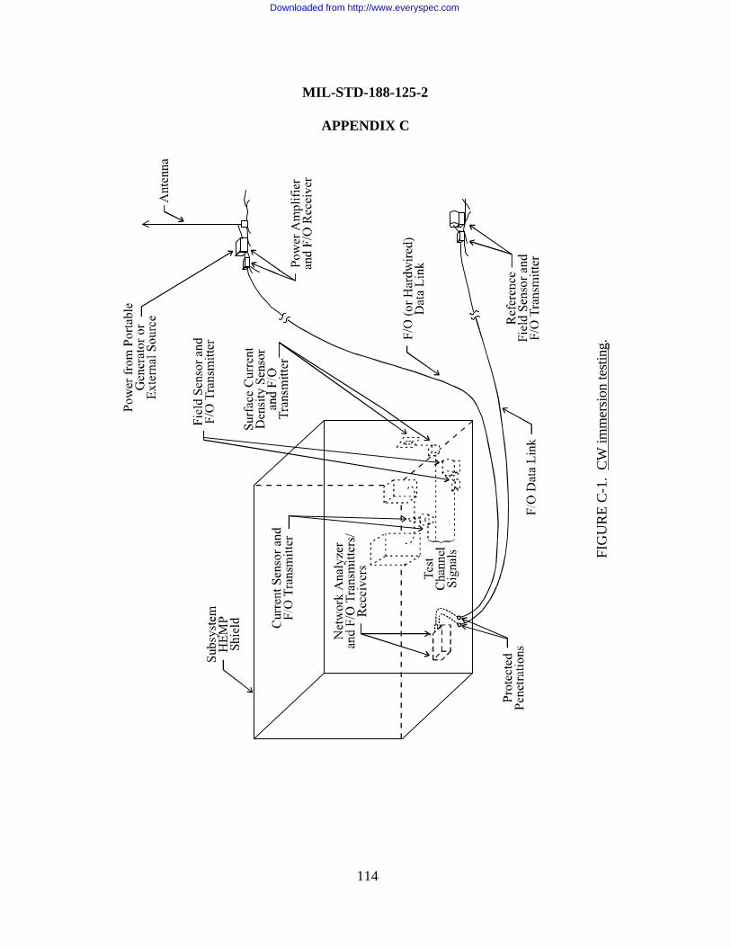
FIG
UR
E C
-1.
CW
imm
ersi
on te
stin
g.
MIL-STD-188-125-2
APPENDIX C
114
Downloaded from http://www.everyspec.com
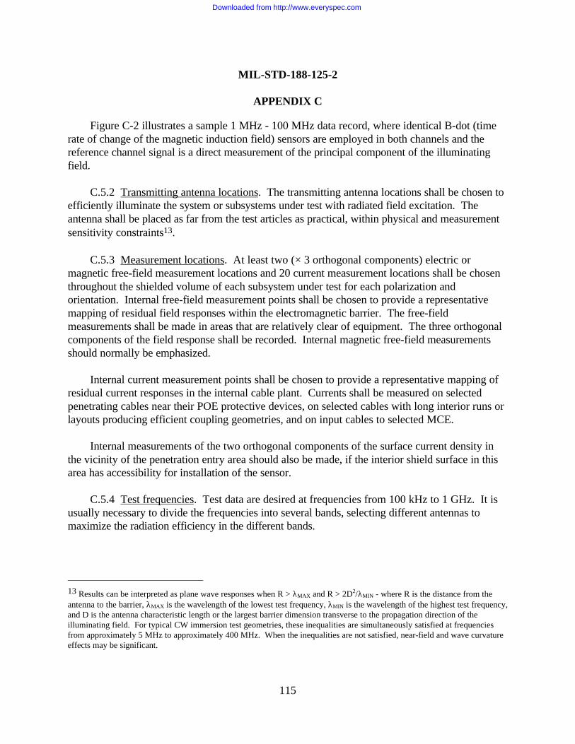
MIL-STD-188-125-2
APPENDIX C
115
Figure C-2 illustrates a sample 1 MHz - 100 MHz data record, where identical B-dot (timerate of change of the magnetic induction field) sensors are employed in both channels and thereference channel signal is a direct measurement of the principal component of the illuminatingfield.
C.5.2 Transmitting antenna locations. The transmitting antenna locations shall be chosen toefficiently illuminate the system or subsystems under test with radiated field excitation. Theantenna shall be placed as far from the test articles as practical, within physical and measurementsensitivity constraints13.
C.5.3 Measurement locations. At least two (× 3 orthogonal components) electric ormagnetic free-field measurement locations and 20 current measurement locations shall be chosenthroughout the shielded volume of each subsystem under test for each polarization andorientation. Internal free-field measurement points shall be chosen to provide a representativemapping of residual field responses within the electromagnetic barrier. The free-fieldmeasurements shall be made in areas that are relatively clear of equipment. The three orthogonalcomponents of the field response shall be recorded. Internal magnetic free-field measurementsshould normally be emphasized.
Internal current measurement points shall be chosen to provide a representative mapping ofresidual current responses in the internal cable plant. Currents shall be measured on selectedpenetrating cables near their POE protective devices, on selected cables with long interior runs orlayouts producing efficient coupling geometries, and on input cables to selected MCE.
Internal measurements of the two orthogonal components of the surface current density inthe vicinity of the penetration entry area should also be made, if the interior shield surface in thisarea has accessibility for installation of the sensor.
C.5.4 Test frequencies. Test data are desired at frequencies from 100 kHz to 1 GHz. It isusually necessary to divide the frequencies into several bands, selecting different antennas tomaximize the radiation efficiency in the different bands.
13 Results can be interpreted as plane wave responses when R > λMAX and R > 2D2/λMIN - where R is the distance from theantenna to the barrier, λMAX is the wavelength of the lowest test frequency, λMIN is the wavelength of the highest test frequency,and D is the antenna characteristic length or the largest barrier dimension transverse to the propagation direction of theilluminating field. For typical CW immersion test geometries, these inequalities are simultaneously satisfied at frequenciesfrom approximately 5 MHz to approximately 400 MHz. When the inequalities are not satisfied, near-field and wave curvatureeffects may be significant.
Downloaded from http://www.everyspec.com
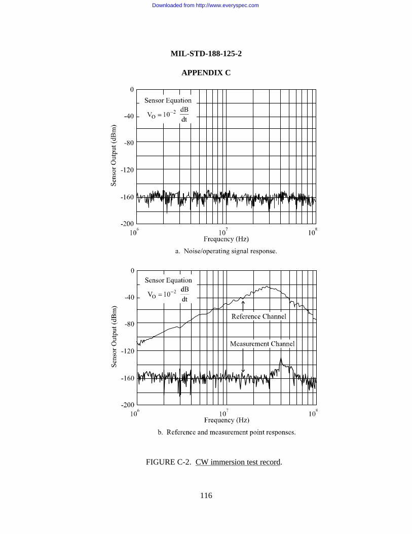
MIL-STD-188-125-2
APPENDIX C
116
FIGURE C-2. CW immersion test record.
Downloaded from http://www.everyspec.com
MIL-STD-188-125-2
APPENDIX C
117
C.5.5 Measurement procedures. CW immersion test procedures shall be as follows:
a. Set up the data acquisition equipment in the desired configuration, and performcalibrations. Minimum sensitivity of the data acquisition system should be - 147 dBm or lower.
b. Set up the transmitting antenna, choose a reference sensor location, and map theilluminating field. The principal component of the illuminating field14 should be at least 1 V/mfrom 1 MHz to 50 MHz and at least 0.1 V/m from 50 MHz to 100 MHz at each subsystem undertest. As a design objective, the principal component of the illuminating field should be at least 0.1V/m from 100 kHz to 1 MHz and at least 0.01 V/m from 100 MHz to 1 GHz at each subsystemunder test.
c. Perform a check of each data acquisition channel to verify link noise immunity.Disconnect the sensor, and terminate the sensor cable in its characteristic impedance. Energizethe radiating source, and record the received signal as a function of frequency.
d. Move the system or subsystems under test into the test area, and configure the unitsunder test in the first orientation. Connect and lay out the external cables. Energize the system orsubsystems, and turn the equipment “on.”
e. Place the measurement sensors, and use preamplifiers as required to obtain the desiredmeasurement sensitivity.
f. Select appropriate narrow band filter and long sweep settings on the network analyzer.With the source and data acquisition equipment operating normally, except that the poweramplifier is turned off, record the noise and operating signal response as a function of frequency.Evaluate the adequacy of the measurement range, and make changes as needed.
g. Turn the power amplifier on and record the reference and measurement point responsesas a function of frequency, using the same filter and sweep time settings as those employed for thenoise and operating signal measurements.
h. Perform data quality control. Annotate and preserve the data records.
14 The illuminating field strength is expressed as Eilluminating or c × Billuminating , where Eilluminating is the electric field
strength, Billuminating is the magnetic induction field strength, and c is the speed of light.
Downloaded from http://www.everyspec.com
MIL-STD-188-125-2
APPENDIX C
118
i. Continue to the next measurement location, and repeat steps e through h.
j. When the measurements in that orientation are completed, reconfigure the units undertest in the next orientation and repeat steps d through i.
k. When the measurements for one transmitting antenna polarization are completed,continue to the next transmitting antenna polarization and repeat steps b through j.
C.5.6 Pass/fail criteria15.
C.5.6.1 Residual internal field measurements. In frequency bands where the measurementrange is less than the required attenuation, internal CW immersion residual field responses shall beconsidered satisfactory when there are no measurement point responses observable above thenoise and operating signal level.
In the frequency band where the measurement range exceeds the required attenuation(expected to be at least 5 MHz to 1 GHz), internal residual field responses shall be consideredsatisfactory when the measurement point responses are below the principal component of theilluminating field by at least the required attenuation. This success criterion is expressed by theequations in the following three paragraphs.
C.5.6.1.1 For residual internal magnetic induction field measurements.
( ) ( )ω×ω≤ω ngilluminatiinternalB BA )(
where
f = frequency (Hz)ω = angular frequency (s-1)
= 2 π f
Binternal (ω) = measured component of the magnetic induction field at ameasurement point inside the electromagnetic barrier (Wb/m2/Hz)
15 These pass/fail criteria apply to all measurements made in the protected volume. Responses measured in a specialprotective volume must not exceed the design values for that special protective volume.
Downloaded from http://www.everyspec.com

MIL-STD-188-125-2
APPENDIX C
119
A (ω) = minimum attenuation as a function of frequency f
= 10
f
3
105 Hz ≤ f ≤ 107 Hz
= 10-4 107 Hz < f ≤ 109 Hz
Billuminating (ω) = principal component of the illuminating magnetic induction fieldat the subsystem under test (Wb/m2/Hz)
C.5.6.1.2 For residual internal electric field measurements.
( ) ( )ω×ω≤ω EA )( E ngilluminatiinternal
where
Einternal (ω) = measured component of the electric field at a measurement pointinside the electromagnetic barrier (V/m/Hz)
Eilluminating (ω) = principal component of the illuminating electric field at thesubsystem under test (V/m/Hz)
C.5.6.1.3 For internal surface current density measurements.
( )ω×µ
ω≤ω ngilluminatiinternal
Bo
)(A )(J S
where
JSinternal (ω) = measured surface current density at a measurement point
inside the electromagnetic barrier (A/m/Hz)
µo = permeability of free space= 4π × 10-7 H/m
Downloaded from http://www.everyspec.com
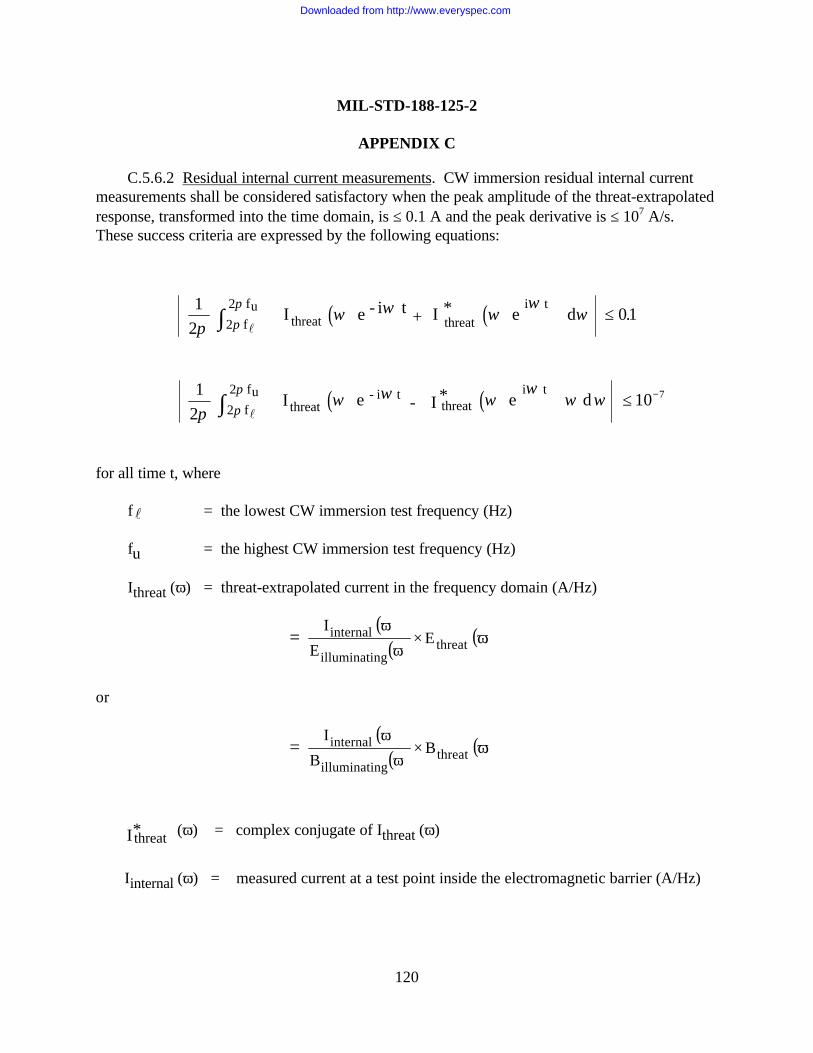
MIL-STD-188-125-2
APPENDIX C
120
C.5.6.2 Residual internal current measurements. CW immersion residual internal currentmeasurements shall be considered satisfactory when the peak amplitude of the threat-extrapolatedresponse, transformed into the time domain, is ≤ 0.1 A and the peak derivative is ≤ 107 A/s.These success criteria are expressed by the following equations:
( ) ( ) e - i t + I * e
d
2 f2 fu
threat threati t1
201
πω ω ω
ωω
π
π
l∫
≤Ι .
( ) ( ) e - *I e
d
2 f2 fu
threat- i t
threat i t1
210 7
πω ω ω
ωω ω
π
π
l∫
≤ −Ι
for all time t, where
fl = the lowest CW immersion test frequency (Hz)
fu = the highest CW immersion test frequency (Hz)
Ithreat (ω) = threat-extrapolated current in the frequency domain (A/Hz)
( )( ) ( )ω×ω
ωΙ= threat
ngilluminati
internal E E
or
( )( ) ( )ω×ω
ωΙ= threat
ngilluminati
internal B B
I*threat (ω) = complex conjugate of Ithreat (ω)
Iinternal (ω) = measured current at a test point inside the electromagnetic barrier (A/Hz)
Downloaded from http://www.everyspec.com
MIL-STD-188-125-2
APPENDIX C
121
Ethreat (ω) = early-time HEMP threat electric field in the frequency domain (V/m/Hz)(see MIL-STD-2169)
Bthreat (ω) = early-time HEMP threat magnetic induction field in the frequency domain(Wb/m2/Hz) (see MIL-STD-2169)
C.5.7 Test failures. Any failure to satisfy the CW immersion pass/fail criteria shall beconsidered a potential HEMP vulnerability. The cause of the potential vulnerability shall beinvestigated and corrected, if possible. After correction of the deficiency, the applicable portionof the CW immersion test procedure shall be repeated.
Downloaded from http://www.everyspec.com
MIL-STD-188-125-2
APPENDIX D
122
THREAT-LEVEL ILLUMINATION TEST PROCEDURESFOR TRANSPORTABLE GROUND-BASED SYSTEMS
D.1 GENERAL
D.1.1 Scope. This Appendix is a mandatory part of this standard. The informationcontained herein is intended for compliance. This Appendix establishes procedures for threat-level illumination testing of the low-risk high-altitude electromagnetic pulse (HEMP) protectionfor transportable ground-based systems with critical, time-urgent missions. The procedures areapplicable for testing other HEMP-hardened systems, when specified by the procurementdocumentation.
D.1.2 Applications. These procedures shall be used for threat-level illumination verificationtesting of the system HEMP protection measures after the system is completed and operational.
D.2 REFERENCED DOCUMENTS
D.2.1 Government documents. The following Government documents form a part of thisAppendix to the extent specified:
MIL-STD-2169 – High-Altitude Electromagnetic Pulse (HEMP)Environment (U) (document is classified Secret)
DI-NUOR-80928 – Nuclear Survivability Test Plan
DI-NUOR-80929A – Nuclear Survivability Test Report
DNA-EMP-1 – Electromagnetic Pulse (EMP) Security ClassificationGuide (U) (document is classified S-RD)
(Copies of documents required by contractors in connection with specific acquisition functionsshould be obtained from the contracting activity or as directed by the contracting officer.)
D.2.2 Non-Government publications. The following publication forms a part of thisAppendix to the extent specified:
IEEE-Std-488.1 – Standard Digital Interface for ProgrammableInstrumentation
Downloaded from http://www.everyspec.com
MIL-STD-188-125-2
APPENDIX D
123
(Applications for copies should be addressed to the Institute for Electrical and ElectronicsEngineers [IEEE], 445 Hoes Lane, Post Office Box 1331, Piscataway, NJ 08855-1331.)
D.3 DEFINITIONS
D.3.1 Threat-level illumination. Illumination of a system or subsystems with a simulatedHEMP environment that approximates significant features of the threat environment specified inMIL-STD-2169.
D.3.2 Field mapping (of a simulator). Measurement of the magnetic and electric fieldcomponents of the simulated HEMP environment, relative to the reference field measurement, atregularly spaced positions throughout the region illuminated by the simulator. Field mapping isperformed when no test article is present. Since it is generally not possible to eliminate groundreflections from a free-field radiating simulator or reflections from the termination of a boundedwave simulator, the field mapping measures the illuminating field from the simulator.
D.3.3 Incident field (from a simulator). The electromagnetic field radiated by the simulator,not including ground reflections, reflections from the termination of a bounded wave simulator, orreflections from a system or subsystems under test. Since it is generally not possible to measurethe incident field from a simulator, it must be computed from measurements of the illuminatingfield.
D.3.4 Illuminating field (from a simulator). The total electromagnetic field from a HEMPsimulator, including ground reflections and reflections from the termination of a bounded wavesimulator, that would be measured during field mapping, as a function of location within theilluminated region, when the system or subsystems under test are not present. Thus, theilluminating field does not include reflections from the system or subsystems under test.
D.3.5 Reference field measurement (in a simulator). A measured field in a threat-levelillumination test used for monitoring the simulator output and determining the incident andilluminating fields. The reference sensor must be placed at a location at which reflections from thesystem or subsystems under test are negligible, such that the reference measurement has a knownrelationship to the illuminating field.
D.3.6 Working volume (of a simulator). The volume within the region illuminated by thesimulator where the incident field satisfies threat-level amplitude, uniformity, and other criteriaspecified in this test procedure (see D.5.1).
Downloaded from http://www.everyspec.com
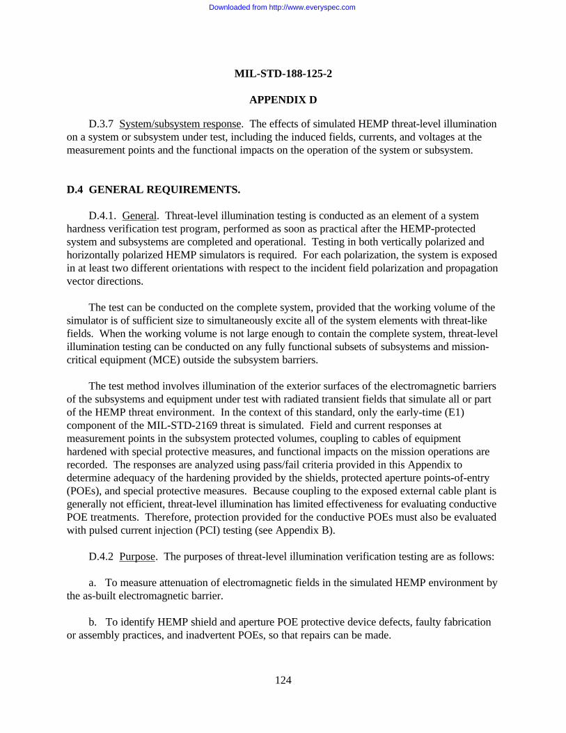
MIL-STD-188-125-2
APPENDIX D
124
D.3.7 System/subsystem response. The effects of simulated HEMP threat-level illuminationon a system or subsystem under test, including the induced fields, currents, and voltages at themeasurement points and the functional impacts on the operation of the system or subsystem.
D.4 GENERAL REQUIREMENTS.
D.4.1. General. Threat-level illumination testing is conducted as an element of a systemhardness verification test program, performed as soon as practical after the HEMP-protectedsystem and subsystems are completed and operational. Testing in both vertically polarized andhorizontally polarized HEMP simulators is required. For each polarization, the system is exposedin at least two different orientations with respect to the incident field polarization and propagationvector directions.
The test can be conducted on the complete system, provided that the working volume of thesimulator is of sufficient size to simultaneously excite all of the system elements with threat-likefields. When the working volume is not large enough to contain the complete system, threat-levelillumination testing can be conducted on any fully functional subsets of subsystems and mission-critical equipment (MCE) outside the subsystem barriers.
The test method involves illumination of the exterior surfaces of the electromagnetic barriersof the subsystems and equipment under test with radiated transient fields that simulate all or partof the HEMP threat environment. In the context of this standard, only the early-time (E1)component of the MIL-STD-2169 threat is simulated. Field and current responses atmeasurement points in the subsystem protected volumes, coupling to cables of equipmenthardened with special protective measures, and functional impacts on the mission operations arerecorded. The responses are analyzed using pass/fail criteria provided in this Appendix todetermine adequacy of the hardening provided by the shields, protected aperture points-of-entry(POEs), and special protective measures. Because coupling to the exposed external cable plant isgenerally not efficient, threat-level illumination has limited effectiveness for evaluating conductivePOE treatments. Therefore, protection provided for the conductive POEs must also be evaluatedwith pulsed current injection (PCI) testing (see Appendix B).
D.4.2 Purpose. The purposes of threat-level illumination verification testing are as follows:
a. To measure attenuation of electromagnetic fields in the simulated HEMP environment bythe as-built electromagnetic barrier.
b. To identify HEMP shield and aperture POE protective device defects, faulty fabricationor assembly practices, and inadvertent POEs, so that repairs can be made.
Downloaded from http://www.everyspec.com
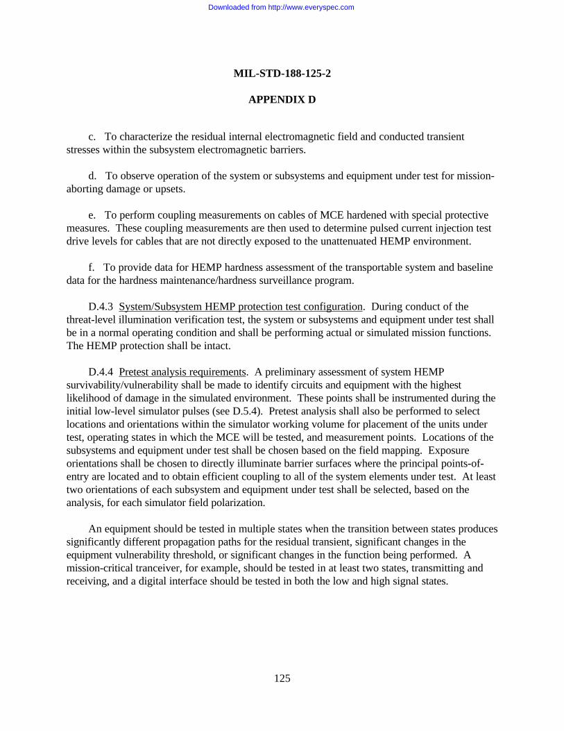
MIL-STD-188-125-2
APPENDIX D
125
c. To characterize the residual internal electromagnetic field and conducted transientstresses within the subsystem electromagnetic barriers.
d. To observe operation of the system or subsystems and equipment under test for mission-aborting damage or upsets.
e. To perform coupling measurements on cables of MCE hardened with special protectivemeasures. These coupling measurements are then used to determine pulsed current injection testdrive levels for cables that are not directly exposed to the unattenuated HEMP environment.
f. To provide data for HEMP hardness assessment of the transportable system and baselinedata for the hardness maintenance/hardness surveillance program.
D.4.3 System/Subsystem HEMP protection test configuration. During conduct of thethreat-level illumination verification test, the system or subsystems and equipment under test shallbe in a normal operating condition and shall be performing actual or simulated mission functions.The HEMP protection shall be intact.
D.4.4 Pretest analysis requirements. A preliminary assessment of system HEMPsurvivability/vulnerability shall be made to identify circuits and equipment with the highestlikelihood of damage in the simulated environment. These points shall be instrumented during theinitial low-level simulator pulses (see D.5.4). Pretest analysis shall also be performed to selectlocations and orientations within the simulator working volume for placement of the units undertest, operating states in which the MCE will be tested, and measurement points. Locations of thesubsystems and equipment under test shall be chosen based on the field mapping. Exposureorientations shall be chosen to directly illuminate barrier surfaces where the principal points-of-entry are located and to obtain efficient coupling to all of the system elements under test. At leasttwo orientations of each subsystem and equipment under test shall be selected, based on theanalysis, for each simulator field polarization.
An equipment should be tested in multiple states when the transition between states producessignificantly different propagation paths for the residual transient, significant changes in theequipment vulnerability threshold, or significant changes in the function being performed. Amission-critical tranceiver, for example, should be tested in at least two states, transmitting andreceiving, and a digital interface should be tested in both the low and high signal states.
Downloaded from http://www.everyspec.com
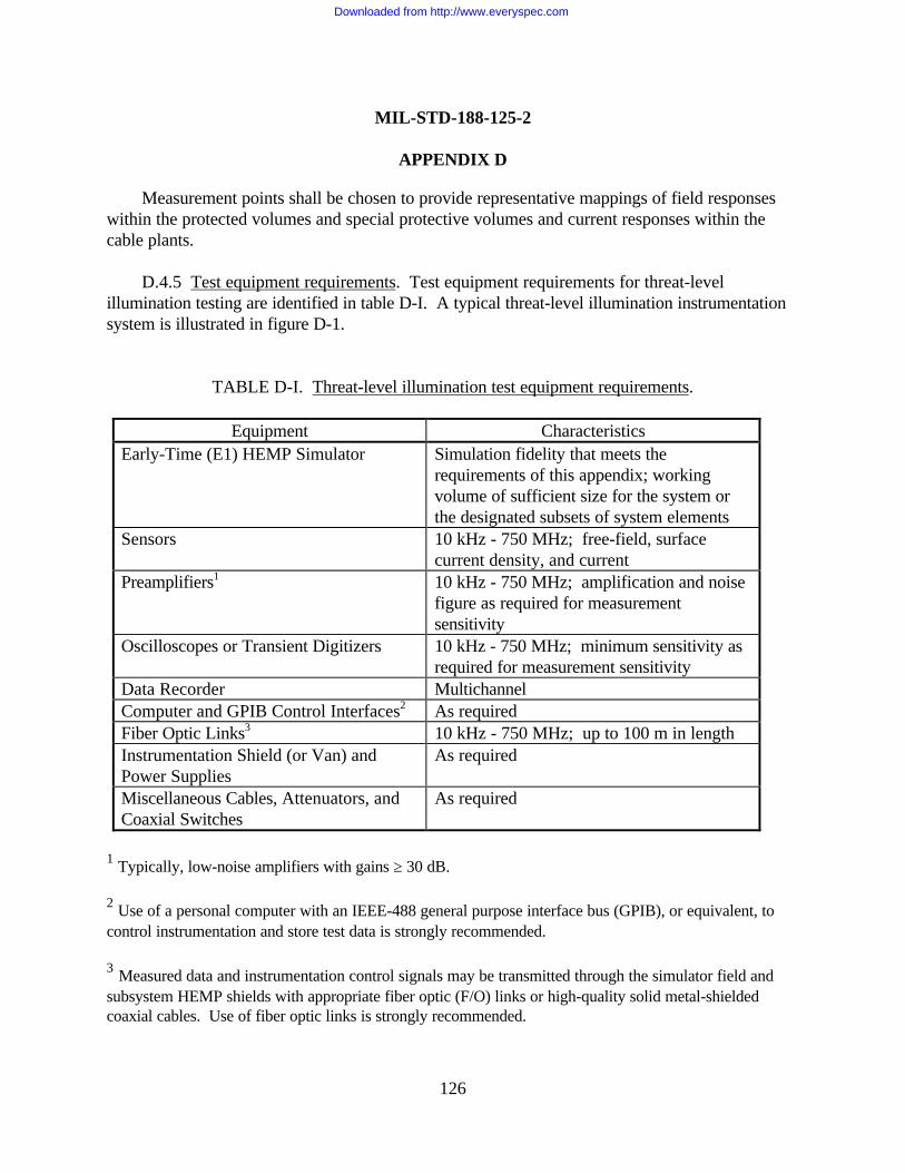
MIL-STD-188-125-2
APPENDIX D
126
Measurement points shall be chosen to provide representative mappings of field responseswithin the protected volumes and special protective volumes and current responses within thecable plants.
D.4.5 Test equipment requirements. Test equipment requirements for threat-levelillumination testing are identified in table D-I. A typical threat-level illumination instrumentationsystem is illustrated in figure D-1.
TABLE D-I. Threat-level illumination test equipment requirements.
Equipment CharacteristicsEarly-Time (E1) HEMP Simulator Simulation fidelity that meets the
requirements of this appendix; workingvolume of sufficient size for the system orthe designated subsets of system elements
Sensors 10 kHz - 750 MHz; free-field, surfacecurrent density, and current
Preamplifiers1 10 kHz - 750 MHz; amplification and noisefigure as required for measurementsensitivity
Oscilloscopes or Transient Digitizers 10 kHz - 750 MHz; minimum sensitivity asrequired for measurement sensitivity
Data Recorder MultichannelComputer and GPIB Control Interfaces2 As requiredFiber Optic Links3 10 kHz - 750 MHz; up to 100 m in lengthInstrumentation Shield (or Van) andPower Supplies
As required
Miscellaneous Cables, Attenuators, andCoaxial Switches
As required
1 Typically, low-noise amplifiers with gains ≥ 30 dB.
2 Use of a personal computer with an IEEE-488 general purpose interface bus (GPIB), or equivalent, tocontrol instrumentation and store test data is strongly recommended.
3 Measured data and instrumentation control signals may be transmitted through the simulator field andsubsystem HEMP shields with appropriate fiber optic (F/O) links or high-quality solid metal-shieldedcoaxial cables. Use of fiber optic links is strongly recommended.
Downloaded from http://www.everyspec.com
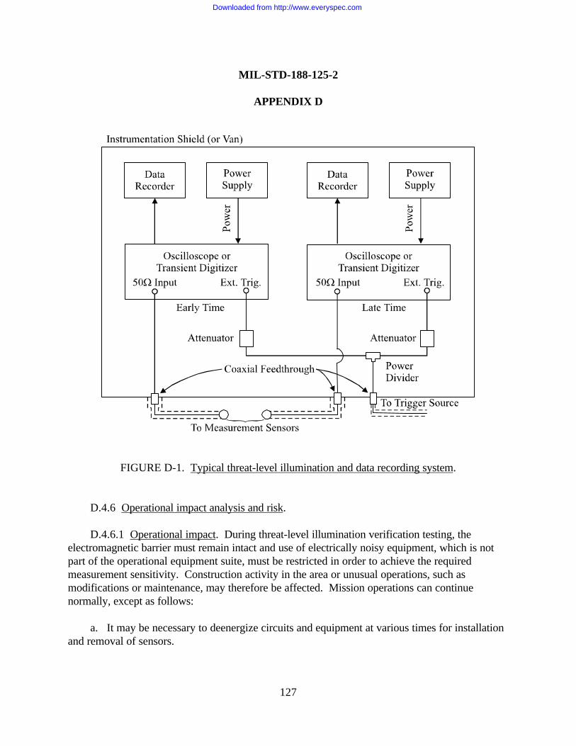
MIL-STD-188-125-2
APPENDIX D
127
FIGURE D-1. Typical threat-level illumination and data recording system.
D.4.6 Operational impact analysis and risk.
D.4.6.1 Operational impact. During threat-level illumination verification testing, theelectromagnetic barrier must remain intact and use of electrically noisy equipment, which is notpart of the operational equipment suite, must be restricted in order to achieve the requiredmeasurement sensitivity. Construction activity in the area or unusual operations, such asmodifications or maintenance, may therefore be affected. Mission operations can continuenormally, except as follows:
a. It may be necessary to deenergize circuits and equipment at various times for installationand removal of sensors.
Downloaded from http://www.everyspec.com
MIL-STD-188-125-2
APPENDIX D
128
b. A special sequence of activities may be required, so that the system or subsystems andequipment can be tested in their various operating states (transmitting, receiving, etc.).
D.4.6.2 Risk. Simulator operation involves the use of high voltages and large currents.Relatively high-voltage and high-current responses may also be induced on external cables andinto interior circuits. Special high-voltage safety precautions apply. Because of the high voltagesand currents, the risk of system or equipment damage cannot be completely eliminated. However,the procedures are designed to minimize this risk.
Radio frequency radiation protection shall be provided for test personnel. A determinationshall be made, as part of the hazards analysis, whether operators can be present within thesubsystem electromagnetic barriers during simulator pulsing. If operators cannot be present,other provisions for monitoring the system or subsystem functionality shall be developed.
D.4.7 Test plan and procedures. A comprehensive, system-specific test plan and detailedtest procedures for system threat-level illumination testing shall be prepared. These may becombined in a single document, or two separate documents may be used. As a minimum, thedocument shall contain the following information:
a. A statement of test objectives.
b. System, subsystem, and LLPM identification and descriptions (including drawings of thesubsystems showing the locations of all POEs, equipment layouts inside the subsystemelectromagnetic barriers, layout of MCE outside the barriers, diagrams of LLPMs, external cableinterconnections, and a description of the HEMP protection measures).
c. Diagrams of the placement of subsystems and equipment under test in the simulatorworking volume and placement of other system elements, which are required to achievefunctionality, with respect to the simulator working volume. Diagrams of the interconnectingcable layouts. The reference sensor location shall also be indicated.
d. Simulator and data acquisition equipment descriptions (including manufacturer, modeland serial numbers, characteristics, and detailed calibration procedures).
e. Detailed test procedures (including system, subsystem, and circuit configurationrequirements; equipment operating states; test configuration diagrams; functional monitoringprovisions; step-by-step procedures; and measurement point locations).
f. Any deviations from the requirements of this Appendix.
Downloaded from http://www.everyspec.com
MIL-STD-188-125-2
APPENDIX D
129
g. Data management (including data quality control procedures, data acceptability criteria,annotation and preservation of data records, and pass/fail criteria).
h. Safety, including electromagnetic radiation and electrical shock hazards.
i. Security (see D.4.10).
j. Schedule, including priority of measurements.
Data item description DI-NUOR-80928, “Nuclear Survivability Test Plan,” shall be used.
D.4.8 Test report requirements. A threat-level illumination test report shall be prepared. Asa minimum, the test report shall contain the following information:
a. System identification and a reference to the applicable test plan.
b. A discussion of any deviations from the test plan or the requirements of this Appendix.
c. Copies of the measured test results, along with sensor calibrations and instrumentationsettings required to convert the data to engineering units. If the data are collected and processedwith an automated data acquisition system and a complete data set will be delivered in electronicformat, samples of the processed data may be provided in the report.
d. Summary tables of the measured internal fields and attenuations and the measuredresidual currents, with comparisons to the pass/fail criteria.
e. Test chronology (including sequence of events; identification of any damage, upsets, orinterference observed and the test and operational conditions under which they occurred; findingsfrom investigation into the causes of test failures, if any; and corrective actions and retest results).
f. Test conclusions, including a definitive statement of the HEMP hardness of the systemand subsystem mission functions, based upon the results of the complete battery of verificationtests and the supporting analysis.
Data item description DI-NUOR-80929A, “Nuclear Survivability Test Report,” shall be used.
D.4.9 Post-test analysis. Post-test analysis of threat-level illumination test data is requiredto correct for sensor and instrumentation system response characteristics and to convert themeasured results into engineering units. Additional analysis of threat-level illumination test datashall be performed to assist in developing a definitive statement of system and subsystem
Downloaded from http://www.everyspec.com
MIL-STD-188-125-2
APPENDIX D
130
hardness. Detailed requirements for the post-test analysis will be established by the sponsoringagency for the test. They will generally include calculations of threat responses from PCI,continuous wave (CW) immersion, and threat-level illumination test data; analysis of verificationtest adequacy; development of hardness conclusions; and recommendations for corrective actions,if required.
D.4.10 Data classification. Test data may be classified. DNA-EMP-1 and the securityclassification guide for the specific system should be consulted for guidance.
D.5 DETAILED REQUIREMENTS.
D.5.1 Incident field requirements in the simulator working volume. The absolute value ofthe peak time-domain electric field amplitude of the simulated incident field shall be greater thanor equal to the peak time-domain amplitude of the early-time (E1) electric field component of theMIL-STD-2169 HEMP threat environment at all points within the working volume, and it shallvary by no more than a factor of two.
As a design objective, the absolute value of the peak time-derivative of the electric fieldamplitude of the simulated incident field should be greater than or equal to the peak time-derivative of the MIL-STD-2169 E1 threat environment at all points within the working volume.As a minimum, the absolute value of the peak time-derivative of the simulated incident electricfield shall be greater than or equal to 50 percent of the peak time-derivative of the MIL-STD-2169 E1 threat environment at all points within the working volume.
The full-width at half-maximum amplitude (FWHM) of the simulated incident electric fieldshall be greater than or equal to the FWHM of the E1 electric field component of the MIL-STD-2169 HEMP threat environment at all points within the working volume.
D.5.2 Test configuration. A typical threat-level illumination test configuration for a singleelement of a HEMP-protected transportable system is illustrated in figure D-2. Two or moresubsystems or items of equipment hardened with special protective measures, up to the completesystem, can be tested simultaneously, if they can fit within the working volume in an
Downloaded from http://www.everyspec.com
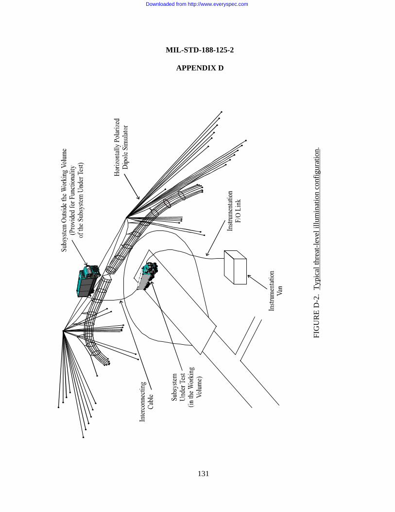
FIG
UR
E D
-2.
Typi
cal t
hrea
t-lev
el il
lum
inat
ion
conf
igur
atio
n.
MIL-STD-188-125-2
APPENDIX D
131
Downloaded from http://www.everyspec.com
MIL-STD-188-125-2
APPENDIX D
132
arrangement representative of the deployment configuration. The units under test shall beoperating and performing actual or simulated mission functions. Other system elements must bepresent, although not necessarily within the working volume, as needed to achieve missionfunctionality of the units under test. Threat-level illumination testing shall be performed in bothvertically polarized and horizontally polarized simulators. At least two orientations shall be testedat each polarization.
The simulated HEMP environment is radiated from the simulator antenna to illuminate thesubsystem under test. The reference sensor, which is located in an area where the measured fieldhas a known relationship to the illuminating and incident fields, monitors the simulator output.Free-field, surface current density, and current sensors monitor the responses at measurementpoints inside (and outside, if desired) the subsystem electromagnetic barrier. Preamplifiers andfiber optic links are used, as required, in the measurement channels. Reference and measurementpoint responses and functional impacts on the operation of the MCE are observed and recorded.
D.5.3 Measurement locations. At least two (× 3 orthogonal components) electric ormagnetic free-field measurement locations and at least 20 current measurement locations shall bechosen inside the shielded volume of each subsystem under test for each polarization andorientation. Internal free-field measurements shall be chosen to provide a representative mappingof residual field responses within the electromagnetic barrier. The free-field measurements shallbe made in areas that are relatively free of equipment. The three orthogonal components of thefield response shall be recorded.
Current measurements within a subsystem electromagnetic barrier shall be chosen to providea representative mapping of residual current responses in the internal cable plant. Currents shallbe measured on selected penetrating cables near their POE protective devices, on selected cableswith long interior runs or layouts producing efficient coupling geometries, and on input cables toselected MCE.
Measurements of the two orthogonal components of the surface current density in thevicinity of the penetration entry area should also be made within the subsystem barrier, if theinterior shield surface in this area has accessibility for installation of the sensor.
Current measurements on MCE hardened with special protective measures shall be made ona sufficient number of power and control/signal/data cables and wires, which are not directlyexposed to the unattenuated HEMP environment, to characterize the conducted electromagneticstresses at the equipment level.
Downloaded from http://www.everyspec.com
MIL-STD-188-125-2
APPENDIX D
133
D.5.4 Test Sequence. To minimize the possibility of system damage from the high-leveltransient electromagnetic fields of the HEMP simulator, the following low-level exposuresequence shall be followed when the transportable system or any subset of the system is firstplaced in the simulator working volume:
a. After the system or subsystems and equipment are set up and operating, instrumentcircuits and equipment identified in the pretest analysis as having the highest likelihood of damagein the simulated HEMP environment.
b. Pulse at the lowest available output from the HEMP simulator, and check the system fordamage or functional indications of probable damage with an increase in the output level. If it isjudged to be safe to proceed, continue pulsing at the same low-level output until responses havebeen measured in all of the identified locations.
c. Linearly extrapolate the low-level responses to threat-level. Select the measurementpoints to be monitored as the simulator output level is increased, based upon an estimate of theratio between the threat-extrapolated responses and the vulnerability thresholds of the associatedequipment.
d. Perform a series of pulses, increasing the simulator output level by no more than 50percent at each step. Based upon the selected measurements, a judgment shall be made whether itis safe to proceed to the next level. Continue this process until threat-level has been reached.
D.5.5 Measurement procedures. Threat-level illumination test procedures shall be asfollows:
a. Set up the data acquisition equipment in the desired configuration, and performinstrument calibrations. Minimum sensitivity of the data acquisition system should be adequatefor measuring transient fields of the order of 0.1 V/m and transient currents of the order of1.0 mA or lower.
b. Set up the simulator. Perform a check of each data acquisition channel to verify linknoise immunity. Disconnect the sensor, and terminate the sensor cable in its characteristicimpedance. Pulse the simulator at threat-level, and record the received signal. Eliminate thecauses of excessive noise responses.
Downloaded from http://www.everyspec.com
MIL-STD-188-125-2
APPENDIX D
134
c. Map the simulator illuminating fields16. Determine the peak amplitude, peak derivative,and FWHM of the incident field pulse, and verify that they satisfy minimum working volumerequirements (see D.5.1) at locations where the system elements under test will be placed.
d. Move the system, subsystems, or equipment under test into the simulator workingvolume and set up in the first orientation. Set up the supporting system elements as required formission functionality of the test articles. Connect and energize the units, and begin performingactual or simulated mission functions.
e. Place measurement sensors for monitoring circuits and equipment identified in the pretestanalysis as having the highest likelihood of damage in the simulated HEMP environment. Usepreamplifiers as required to obtain the desired measurement sensitivity.
f. Perform the low-level exposure sequence (see D.5.4), to minimize the possibility that thesystem, subsystems, or equipment will be damaged by threat-level simulator pulses.
g. Place sensors at the measurement points. Establish the required system/subsystem,equipment state, and test configurations.
h. Pulse the simulator at threat level, and record the reference and measurement pointresponses. Perform data quality control, and annotate and preserve the data records. Record anydamage or upsets of the MCE, along with the test and operational conditions that existed at thetime the abnormal occurrence was observed, for inclusion in the test chronology.
i. Compare the measured results and functional observations to the pass/fail criteria (seeD.5.6). If the results are not satisfactory, halt the test and investigate the cause of the failure.Additional simulator shots at any output level may be made as part of this investigation. Takeappropriate corrective actions. Repeat steps g and h after the corrective actions have beencompleted.
j. When all required measurements in that state have been taken, continue to the next stateto be tested and repeat steps g through i.
k. When the measurements in that orientation are completed, reconfigure the units undertest in the next orientation and repeat steps e through j. When approved by the sponsoringagency for the test, the low-level exposure sequence can be abbreviated after the first orientation. 16 The illuminating field strength is expressed as Eilluminating or c × Billuminating , where Eilluminating is the electric
field strength, Billuminating is the magnetic induction field strength, and c is the speed of light.
Downloaded from http://www.everyspec.com
MIL-STD-188-125-2
APPENDIX D
135
l. When the subset of subsystems and equipment has been tested in all required states andorientations, remove the units under test from the simulator working volume. Move the nextsubset into the working volume and repeat steps d through j.
m. Proceed to the second, oppositely polarized simulator. Repeat steps a through l of thesemeasurement procedures.
D.5.6 Pass/fail criteria.
D.5.6.1 Residual internal magnetic induction field measurements17. Measurements of theresidual internal magnetic induction field shall be considered satisfactory when the peak absolutevalue of the amplitude of the response at each magnetic field measurement point within theprotected volume of a hardened subsystem under test is below the peak amplitude of the MIL-STD-2169 E1 magnetic induction field by at least 80 dB.
D.5.6.2 Residual internal electric field measurements17. Measurements of the residualinternal electric field shall be considered satisfactory when the peak absolute value of theamplitude of the response at each electric field measurement point within the protected volume ofa hardened subsystem under test is below the peak amplitude of the MIL-STD-2169 E1 electricfield by at least 80 dB.
D.5.6.3 Residual internal current measurements17. Measurements of the residual internaltransient current shall be considered satisfactory when the peak absolute value of the amplitude ofthe response at each current measurement point within the protected volume of a hardenedsubsystem under test is ≤ 0.1 A and the peak absolute value of its derivative is ≤ 1×10⁷ A/s.
D.5.6.4 Functional pass/fail criteria. Hardening of the MCE within the protected volume ofa hardened subsystem under test shall be considered satisfactory when no mission-abortingdamage or upsets, as determined by the operational authority for the system, occur during threat-level illumination verification testing.
HEMP protection of MCE hardened with special protective measures shall be consideredsatisfactory when no mission-aborting damage or upsets, as determined by the operationalauthority for the system, occur during threat-level illumination verification testing and no mission-aborting damage or upsets occur during the associated PCI testing required by this standard. 17 These pass/fail criteria apply to all measurements made in the protected volume. Responses measured in a specialprotective volume must not exceed the design values for that special protective volume.
Downloaded from http://www.everyspec.com
MIL-STD-188-125-2
APPENDIX D
136
D.5.7 Test failures. Any failure to satisfy the threat-level illumination pass/fail criteria shallbe considered a potential HEMP vulnerability. The cause of the potential vulnerability shall beinvestigated and corrected, if possible. After correction of the deficiency, the applicable portionof the threat-level illumination test procedure shall be repeated.
Downloaded from http://www.everyspec.com
MIL-STD-188-125-2
Custodians: Preparing Activity:Army - CR DSWA - DSNavy - ECAir Force - 90DISA - DC1NSA - NS
(Project TCSS-0037-001)
Review Activities:OASD - SEArmy - AC, PTNavy - CG, MC, NC, OM, TDAir Force - 02, 13, 17, 19, 21, 29, 33, 93DIA - DIDISA - DC4DLA - DHDMA - MPJSC - JSUSSPACECOM - US
Civil Agencies Coordinating Activities:TRANSPORTATION - OST
137
Downloaded from http://www.everyspec.com
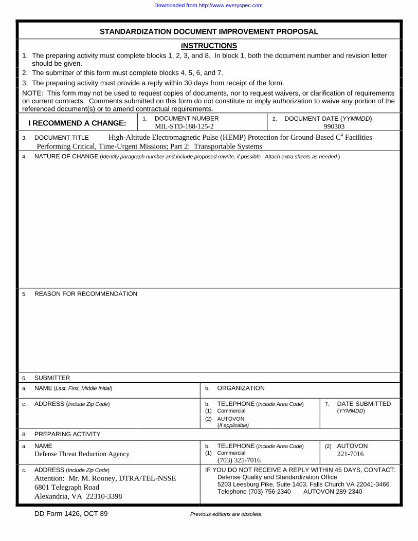
STANDARDIZATION DOCUMENT IMPROVEMENT PROPOSAL
INSTRUCTIONS1. The preparing activity must complete blocks 1, 2, 3, and 8. In block 1, both the document number and revision letter
should be given.2. The submitter of this form must complete blocks 4, 5, 6, and 7.
3. The preparing activity must provide a reply within 30 days from receipt of the form.
NOTE: This form may not be used to request copies of documents, nor to request waivers, or clarification of requirementson current contracts. Comments submitted on this form do not constitute or imply authorization to waive any portion of thereferenced document(s) or to amend contractual requirements.
I RECOMMEND A CHANGE:1. DOCUMENT NUMBER
MIL-STD-188-125-22. DOCUMENT DATE (YYMMDD)
990303
3. DOCUMENT TITLE High-Altitude Electromagnetic Pulse (HEMP) Protection for Ground-Based C4 FacilitiesPerforming Critical, Time-Urgent Missions; Part 2: Transportable Systems
4. NATURE OF CHANGE (Identify paragraph number and include proposed rewrite, if possible. Attach extra sheets as needed.)
5. REASON FOR RECOMMENDATION
6. SUBMITTER
a. NAME (Last, First, Middle Initial) b. ORGANIZATION
c. ADDRESS (Include Zip Code) b. TELEPHONE (Include Area Code)(1) Commercial
7. DATE SUBMITTED(YYMMDD)
(2) AUTOVON(If applicable)
8. PREPARING ACTIVITY
a. NAME Defense Threat Reduction Agency
b. TELEPHONE (Include Area Code)(1) Commercial
(703) 325-7016
(2) AUTOVON221-7016
c. ADDRESS (Include Zip Code)
Attention: Mr. M. Rooney, DTRA/TEL-NSSE6801 Telegraph RoadAlexandria, VA 22310-3398
IF YOU DO NOT RECEIVE A REPLY WITHIN 45 DAYS, CONTACT:Defense Quality and Standardization Office5203 Leesburg Pike, Suite 1403, Falls Church VA 22041-3466Telephone (703) 756-2340 AUTOVON 289-2340
DD Form 1426, OCT 89 Previous editions are obsolete.
Downloaded from http://www.everyspec.com