Embed Size (px)
Citation preview
� !
Department of Computer Science Visual Impaired Helper
!A Mini-thesis
By Kurt Sebastian Jacobs
!Supervisor: Mehrdad Ghaziasgar
Date: 11 November 2013
Page � of �1 40
Abstract
Studies conducted in June 2012 indicate that 285 Million people are visually impaired.Approximately 90% of the worlds visually impaired are situated in third world countries.It is estimated that 19 million children under the age of 15 are visually impaired and approximately 1.4 million are blind for life. Information is provided courtesy of the World Health Organisation
Those that are visually impaired and perhaps even blind would also like to live life to the fullest but are currently restricted by walking sticks and guide dogs. The problem with guide dogs is that they need to be trained, this, however, takes time and requires a lot to be invested in these dogs. One can thus expect that such dogs cost a good sum of money and they are not always readily available. This affects the visually impaired person for cost because they will have to feed the dog and look after them just for Page � of �2 40
said person to be able to move around and navigate.This project aims to solve this problem through a technological approach, A video sensor (Kinect Sensor) will be used to detect objects in the real world as input and calculate the possible route(s) the user can possibly take to not collide with any object within the range of the video
sensors field of vision. The information obtained by way of the sensor is then relayed to an Arduino Micro Controller which in turn controls the vibration sensors on the headband unit. The headband unit contains little pockets in which each vibration sensor is stored, these will vibrate accordingly and only vibrate when the user can move in that direction. Both the Kinect Sensor and Arduino Micro Controller are connected through a notebook computer.
Page � of �3 40
Table of Contents Chapter 1
1. Introduction 7
1.1 Kinect SDK 7
1.2 OpenCV 7
1.3 EMGU CV 8
1.4 Current Research 8
Chapter 2
2. User Requirements 9
2.1 Users View of The Problem 9
2.2 Description of The Problem 9
2.3 Expectation From The Solution 10
2.4 Not To Be Expected From The Solution 10
Chapter 3
3. Requirements Analysis 11
3.1 Designers View, Breakdown of the problem 11
3.2 Complete Analysis of the problem 12
3.2.1 Detecting Objects In Real Time 12
3.2.2 Obtaining The Closest Distance 12
3.2.3 How Does Arduino Get Its Data? 12
3.2.4 Controlling the headband 13
3.2.5 Calculating Estimated Real World Size 13
Chapter 4
4. User Interface Specification 14
Chapter 5
Page � of �4 40
5. Project Design and Development 15
5.1 High Level Design for Computer Vision 15
5.1.1 A Description of the Concepts 15
5.1.1.1 OpenCV 15
5.1.1.2 Contour Detection 15
5.1.1.3 Minimum Bounding Area Rectangle 16
5.1.1.4 Kinect API 16
5.1.2 Collision Detection – Binary Decision Diagram - Relationships Between Objects 16
5.2 Low Level Design for Computer Vision 18
5.2.1 Capture Frames using an event handler model 18
5.2.2 Convert Kinect Frame to OpenCV image data structure 19
5.2.3 Detect contours/blobs! ! ! ! ! ! ! ! 19!5.2.4 Draw minimum area bounding box 20
5.2.5 Collision detection and path finding algorithms 20
5.2.6 Closest Distance Calculation 21
5.3 High Level Design for Engineering 22
5.3.1 A Description of the Concepts 22
5.3.1.1 Arduino SDK 22
5.3.2 Relationships Between Objects 22
5.4 Low Level Design for Engineering 23
5.4.1 Start Serial Input 24
5.4.2 Read Each Char 24
5.4.3 Vibrate Motors 25
Chapter 6
6. Testing, Analysis & Results 26
Page � of �5 40
6.1 Experiment 1 - Distance Accuracy 256.2 Experiment 2 - BLOB Detection and Collision Detection 286.3 Experiment 3 - Testing The System For Getting Closest Distance For Objects of Different Sizes & Shapes 306.4 Experiment 4 - Width of Objects Apart 326.5 Experiment 5 - Frame Rate Impact 34Chapter 7 7. Limitations & Caveats 36
Chapter 8
8. Code Documentation 37
Page � of �6 40
1. Introduction
1.1 KinectSDK
The KinectSDK is a Software Development Kit that allows a computer running Windows to interface with the Kinect Sensor, It supports three languages, Microsofts very own VB.NET and C# and also C ++. I have chosen to use the C# version of the SDK.1.2 OpenCV (Open Computer Vision) Library
OpenCV is an open source computer vision library which was originally developed by the Intel Corporation. OpenCV was originally developed in C and currently its primary interface is C++ however since then a number of other language implementations have been and added. OpenCV is completely cross-platform so it works on all the platforms, Mac OS, Linux and Windows. OpenCV contains a myriad of functions within the library, somewhere around the region of 500 functions.
Page � of �7 40
1.3 EMGU CV
EmguCV is a .NET Wrapper for the OpenCV Library and allows for the use of OpenCV functions in .NET languages such as C# and VB.NET.1.4 Current Research
There have been quite a few projects that have attempted to simplify and better the way the visually impaired navigate, amongst others there is the Eye Stick by Yanko Design which has a camera mounted into the walking stick and vibrates at the handle if the user is about to collide with an object. Another implementation is the attachment of a robot to a walking stick which essentially functions in a similar fashion to the Eye Stick.!
Page � of �8 40
2. User Requirements
This section will describe the requirements that relate to the user and the problems they face. This phase, in which I elicit the user requirements is crucial to the success and correctness of the solution.2.1 Users View of The Problem
The user requires a cost effective solution that allows him or her to navigate there way around objects in the real world. The system should allow the user to navigate without colliding into objects by using an active video stream from the Kinect Sensor. This information should then be used to provide feedback.2.2 Description of the problem
The objective here is to remove the need for a guide dog or generic walking stick and replace it by use of technology. Guide dogs are not a cost effective way of navigating for the visually impaired.!Page � of �9 40
2.3 Expectations from the solution
The user will be able to navigate in any direction in which the video sensor has field of vision and can detect BLOBs. The focus of this is to allow the user with a means of navigating by themselves.This is purely for research and could be used for future implementations.2.4 Not to be expected from the solution
There are a number of caveats that the solution, at present, will not attempt to solve. A few of these examples are that the system will not detect stairs and/or a case like a swimming pool. No GPS system will currently be incorporated. The system will not be the most comfortable to wear, consider it a pre-alpha version of what it is intended to be.!
Page � of �10 40
3. Requirements Analysis
3.1 Designers View, Breakdown of the problem
Users require a cost effective way to navigate around without the use of guide dogs because they are costly, take time to train and are not always readily available for adoption. The input into the system can possibly be a prerecorded video stream (captured through the Kinect i.e Depth and RGB frames) or a live stream from the Kinect Sensor. The Notebook of PC captures the stream from the Kinect Sensor and then objects will be detected on a per-frame basis and send the processed information to the Arduino Micro Controller. The Arduino Micro Controller then uses this processed information from the Kinect Sensor to decide which motor(s) to vibrate.!!!!
Page � of �11 40
3.2 Complete Analysis of the problem
3.2.1 Detecting Objects In Real Time
A Kinect Sensor captures the frames and sends them to the PC, an algorithm is then used to check each for BLOBs. Once the BLOBs are detected they are categorised into segments. Once categorised the closest distance is obtained and converted to an intensity (ranging between 0 - 255) based on depth. This data is stored as a comma separated string.3.2.2 Obtaining The Closest Distance The closest distance is obtained by accessing the depth pixels array that is stored when the Kinect’s IR depth sensor reads the Infrared data from the Kinect IR emitter.3.2.3 How Does Arduino Get Its Data?
The Arduino board is programmed in C and the instructions are then flashed to the board via USB, in the program instructions will be added that allows Arduino to listen on a Page � of �12 40
serial communications port. All data will be transferred via serial communications.3.2.4 Controlling the headband
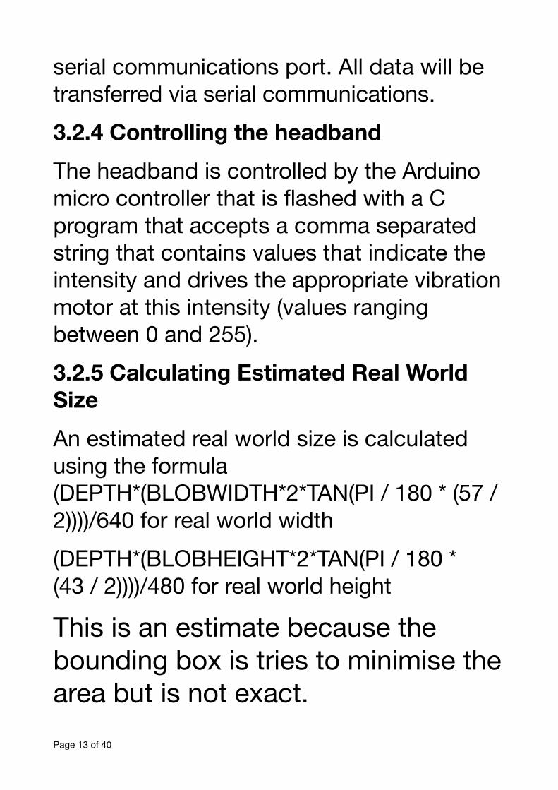
The headband is controlled by the Arduino micro controller that is flashed with a C program that accepts a comma separated string that contains values that indicate the intensity and drives the appropriate vibration motor at this intensity (values ranging between 0 and 255).3.2.5 Calculating Estimated Real World Size An estimated real world size is calculated using the formula (DEPTH*(BLOBWIDTH*2*TAN(PI / 180 * (57 / 2))))/640 for real world width(DEPTH*(BLOBHEIGHT*2*TAN(PI / 180 * (43 / 2))))/480 for real world height
This is an estimate because the bounding box is tries to minimise the area but is not exact.Page � of �13 40
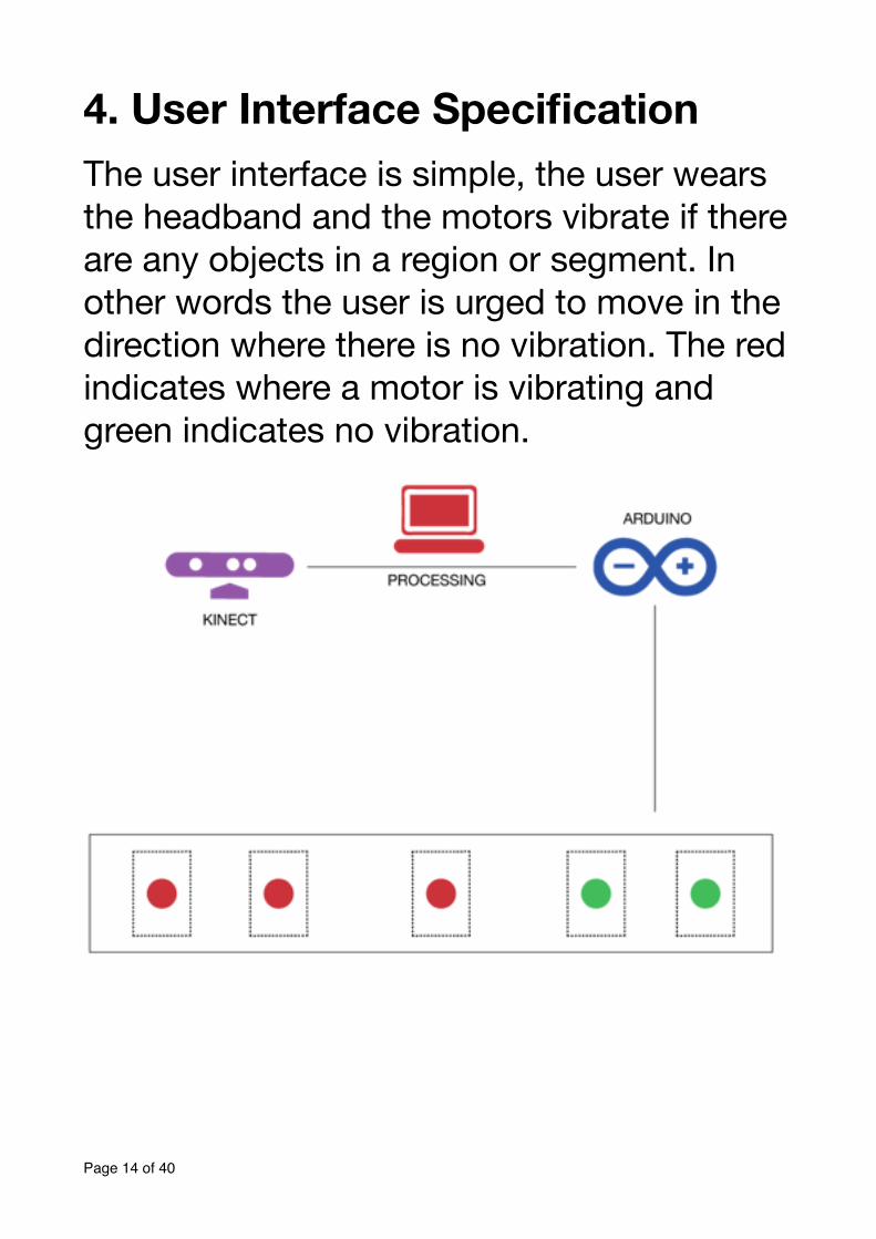
4. User Interface Specification The user interface is simple, the user wears the headband and the motors vibrate if there are any objects in a region or segment. In other words the user is urged to move in the direction where there is no vibration. The red indicates where a motor is vibrating and green indicates no vibration.
!!
Page � of �14 40
5. Project Design and Development
In this chapter I will discuss the high level design for both the engineering and computer vision components. There is no visual user interface element in this project besides interfaces for debugging purposes.5.1 High Level Design for Computer Vision
The computer vision component is implemented in C# using the C# version of the Kinect API and EMGUCV C# wrapper for integration of the OpenCV library. We have a look at a high level abstraction of the system in this section.5.1.1 A Description of the Concepts
5.1.1.1 OpenCV - OpenCV is a library of programming functions mainly aimed at real time computer vision and is focused mainly on real-time image processing.5.1.1.2 Contour Detection - The edge pixels are assembled into contours. The largest contour is detected and is the only Page � of �15 40
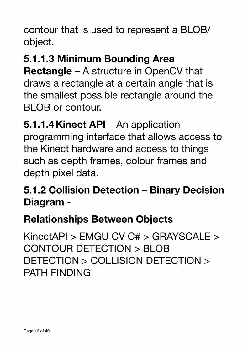
contour that is used to represent a BLOB/ object.5.1.1.3 Minimum Bounding Area Rectangle – A structure in OpenCV that draws a rectangle at a certain angle that is the smallest possible rectangle around the BLOB or contour.5.1.1.4 Kinect API – An application programming interface that allows access to the Kinect hardware and access to things such as depth frames, colour frames and depth pixel data.5.1.2 Collision Detection – Binary Decision Diagram -
Relationships Between Objects
KinectAPI > EMGU CV C# > GRAYSCALE > CONTOUR DETECTION > BLOB DETECTION > COLLISION DETECTION > PATH FINDING
Page � of �16 40
1. Kinect captures frames2. Convert image to grayscale OpenCV image
3. Collision detection, typically refers to the computational problem of detecting the intersection of two or more objects. can be considered as a compressed representation of sets or relations.4. Detect contours/blobs in frame Draw minimum area bounding box detect collisions in image segments.Page � of �17 40
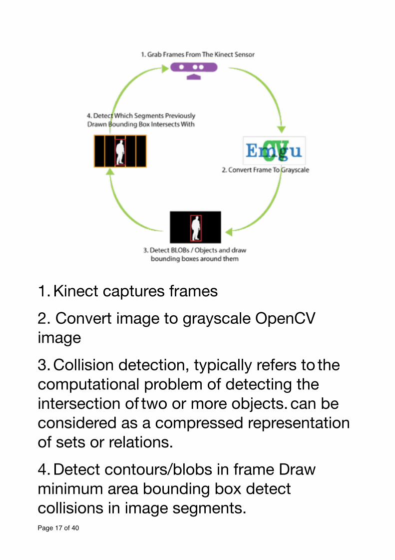
5.2 Low Level Design for Computer Vision
!5.2.1 Capture Frames using an event handler model this.sensor.AllFramesReady += this.sensor_AllFramesReady; Using the above code frames will be grabbed when they are available from the Kinect sensor i.e. the Kinect notifies the system when a new frame is available.Page � of �18 40
5.2.2 Convert Kinect Frame to OpenCV image data structure
Image<Bgr, Byte> openCVImg = new Image<Bgr,byte>(depthBmp.ToBitmap());Image<Gray, byte> gray_image =
openCVImg.Convert<Gray, byte>();Before we are able to make use of the OpenCV library and its many functions it is necessary to have a helper class that hosts functions that convert between Kinect API and OpenCV structures. Using an ImageHelper.cs class that hosts these functions I was able to convert between a Kinect depth image to a grayscale OpenCV image structure.5.2.3 Detect contours/blobs
Contour<System.Drawing.Point> contours =
gray_image.FindContours(Emgu.CV.CvEnum.CHAIN_APPROX_METHOD.CV_CHAIN_APPROX_SIMPLE,Emgu.CV.CvEnum.RETR_TYPE.CV_RETR_EXTERNAL,stor);
Page � of �19 40
We need to detect the outermost contours only and use that as out BLOB or object. A few modes exist for contour detection such as CV_RETR_LIST and CV_RETR_CCOMP but we are only interested in setting the mode to CV_RETR_EXTERNAL because we would only like the outermost contour.5.2.4 Draw minimum area bounding box
MCvBox2D box = contours.GetMinAreaRect();openCVImg.Draw(box, new
Bgr(System.Drawing.Color.Red),2);We draw a minimum bounding box around the contour detected above and this is necessary so that we can calculate the real world size in height and width as well as do the collision detection. 5.2.5 Collision detection and path finding algorithms
A collision detection function accepts a bounding box and the closest distance.
Page � of �20 40
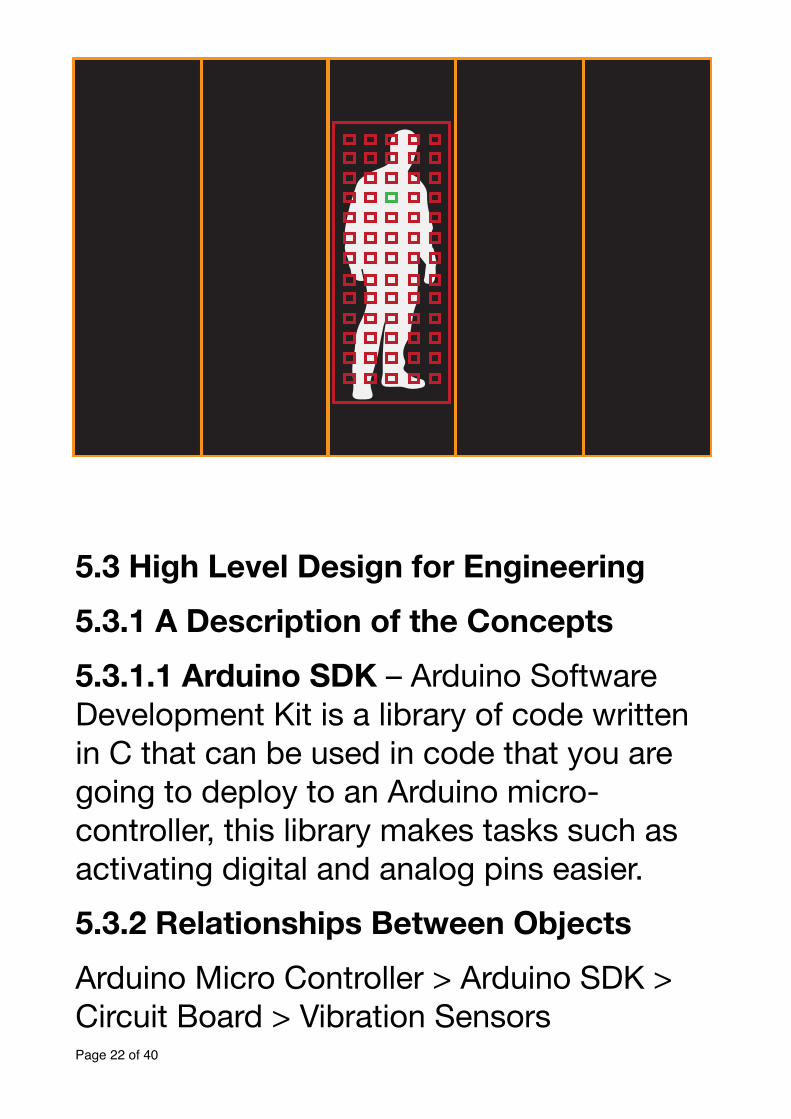
System.Drawing.Rectangle.IntersectsWith(System.Drawing.Rectangle)Check If bounding box intersects with a segment.Return the array for each case where a bounding box intersects with a segment.5.2.6 Closest Distance Calculation We get the closest distance for the BLOB from the Kinect DepthPixel data structure that stores the DepthPixels from the IR sensor. Using the formula (X + Y * 640) we can obtain the position of the depth value.The way in which the closest distance is calculated is a set of sample points are are drawn in a BLOB bounding box and of those sample points the minimum distance is selected as the closest distance. This is shown in the figure below. The closest distance is then mapped to an intensity of vibration force between 0 and 255.!!!Page � of �21 40
!!5.3 High Level Design for Engineering 5.3.1 A Description of the Concepts
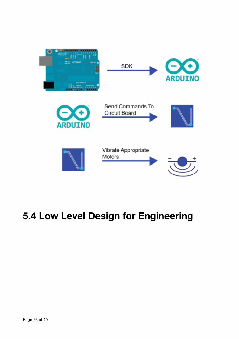
5.3.1.1 Arduino SDK – Arduino Software Development Kit is a library of code written in C that can be used in code that you are going to deploy to an Arduino micro-controller, this library makes tasks such as activating digital and analog pins easier.5.3.2 Relationships Between Objects
Arduino Micro Controller > Arduino SDK > Circuit Board > Vibration Sensors
Page � of �22 40
5.4 Low Level Design for Engineering
Page � of �23 40
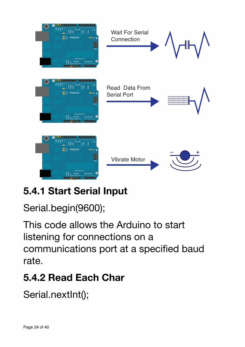
5.4.1 Start Serial Input Serial.begin(9600);This code allows the Arduino to start listening for connections on a communications port at a specified baud rate.5.4.2 Read Each Char
Serial.nextInt();
Page � of �24 40
Wait For Serial Connection
Read Data From Serial Port
Vibrate Motor
This code allows for us to read each intensity from the string that is sent via serial communications.5.4.3 Vibrate Motors
AnalogWrite (VibratorNumber, IntensityOfVibrator);This sends an instruction to vibrate the specified vibration motor at a certain intensity.
Page � of �25 40
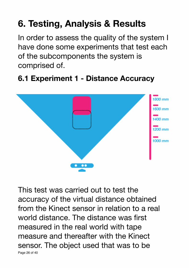
6. Testing, Analysis & Results In order to assess the quality of the system I have done some experiments that test each of the subcomponents the system is comprised of.6.1 Experiment 1 - Distance Accuracy
!This test was carried out to test the accuracy of the virtual distance obtained from the Kinect sensor in relation to a real world distance. The distance was first measured in the real world with tape measure and thereafter with the Kinect sensor. The object used that was to be Page � of �26 40
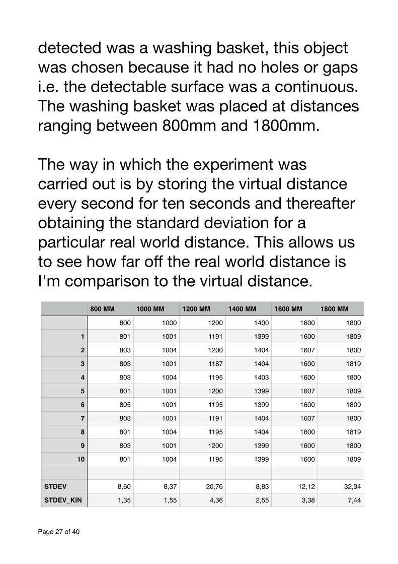
detected was a washing basket, this object was chosen because it had no holes or gaps i.e. the detectable surface was a continuous. The washing basket was placed at distances ranging between 800mm and 1800mm. !The way in which the experiment was carried out is by storing the virtual distance every second for ten seconds and thereafter obtaining the standard deviation for a particular real world distance. This allows us to see how far off the real world distance is I'm comparison to the virtual distance.
Page � of �27 40
800 MM 1000 MM 1200 MM 1400 MM 1600 MM 1800 MM
800 1000 1200 1400 1600 1800
1 801 1001 1191 1399 1600 1809
2 803 1004 1200 1404 1607 1800
3 803 1001 1187 1404 1600 1819
4 803 1004 1195 1403 1600 1800
5 801 1001 1200 1399 1607 1809
6 805 1001 1195 1399 1600 1809
7 803 1001 1191 1404 1607 1800
8 801 1004 1195 1404 1600 1819
9 803 1001 1200 1399 1600 1800
10 801 1004 1195 1399 1600 1809
STDEV 8,60 8,37 20,76 8,83 12,12 32,34
STDEV_KIN 1,35 1,55 4,36 2,55 3,38 7,44
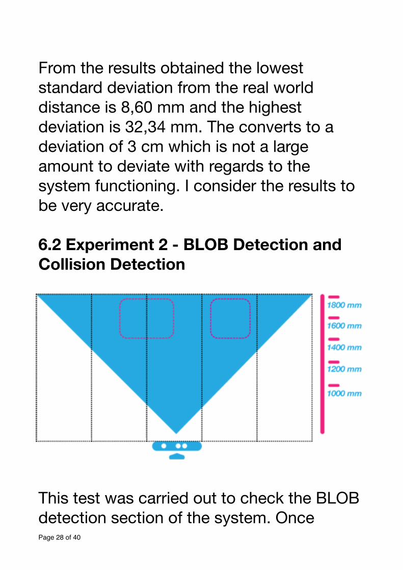
!From the results obtained the lowest standard deviation from the real world distance is 8,60 mm and the highest deviation is 32,34 mm. The converts to a deviation of 3 cm which is not a large amount to deviate with regards to the system functioning. I consider the results to be very accurate.!6.2 Experiment 2 - BLOB Detection and Collision Detection
!This test was carried out to check the BLOB detection section of the system. Once Page � of �28 40
detected it is checked which segment the BLOB is colliding with. Three objects were used in this experiment, a chair, a washing basket, and a tiki head.!Initially the tiki head which spanned only one segment was placed within each segment and tested to check if it was detected correctly and whether the collision per segment was correct. The results obtained were correct and the tiki head was detected correctly in each segment.!The chair was placed spanning two segments, tested to check if it was detected correctly and whether both segments intersected. The results obtained indicated that the BLOB was detected correctly and both segments were intersected. !The washing was also placed spanning two segments, tested to check if it was detected correctly and whether both segments intersected. The results obtained indicated
Page � of �29 40
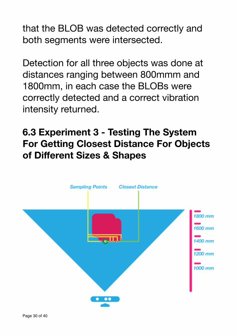
that the BLOB was detected correctly and both segments were intersected.!Detection for all three objects was done at distances ranging between 800mmm and 1800mm, in each case the BLOBs were correctly detected and a correct vibration intensity returned.!6.3 Experiment 3 - Testing The System For Getting Closest Distance For Objects of Different Sizes & Shapes !
Page � of �30 40
This test was carried out to test the accuracy of the system in obtaining the closest distance for objects of various shapes and sizes. The objects that I have used for the test were a washing basket, a chair, and a tiki head.!It must be understood that the way in which the closest distance is determined is by drawing a grid of sample points within a detected BLOBs bounding area. The distances are then obtained via the Kinect API and a minimum distance is selected from these sample points. The amount of sample points selected can be increased by adjusting the INTERNAL_BLOB_COUNT variable.!With an initial INTERNAL_BLOB_COUNT value of 3 the chair was placed atop the washing basket and with the legs protruding outwards facing the Kinect. The closest part of the chair i.e. the legs, had a real world distance of 1150 mm. Upon testing, the sensor obtained a virtual distance of 1309 Page � of �31 40
mm. This distance was however not the closest distance, it was the distance to a peg that holds the legs together.!I then increased the value of the INTERNAL_BLOB_COUNT to a 8 point sampling grid. The chair remained at in the same position still at 1550 mm. The results obtained after adjusting the amount of sampling points were much better and realistic ranging between 1155 mm and 1159 mm.!6.4 Experiment 4 - Width of Objects Apart !This test was carried out to test what the distance between objects need to be for someone to move through comfortably i.e. the distance between two objects for which the centre vibrator does not vibrate.!Two chairs were used in the test and the distance between them was adjusted until they were closest together without the centre vibrator motor vibrating to obtain the Page � of �32 40
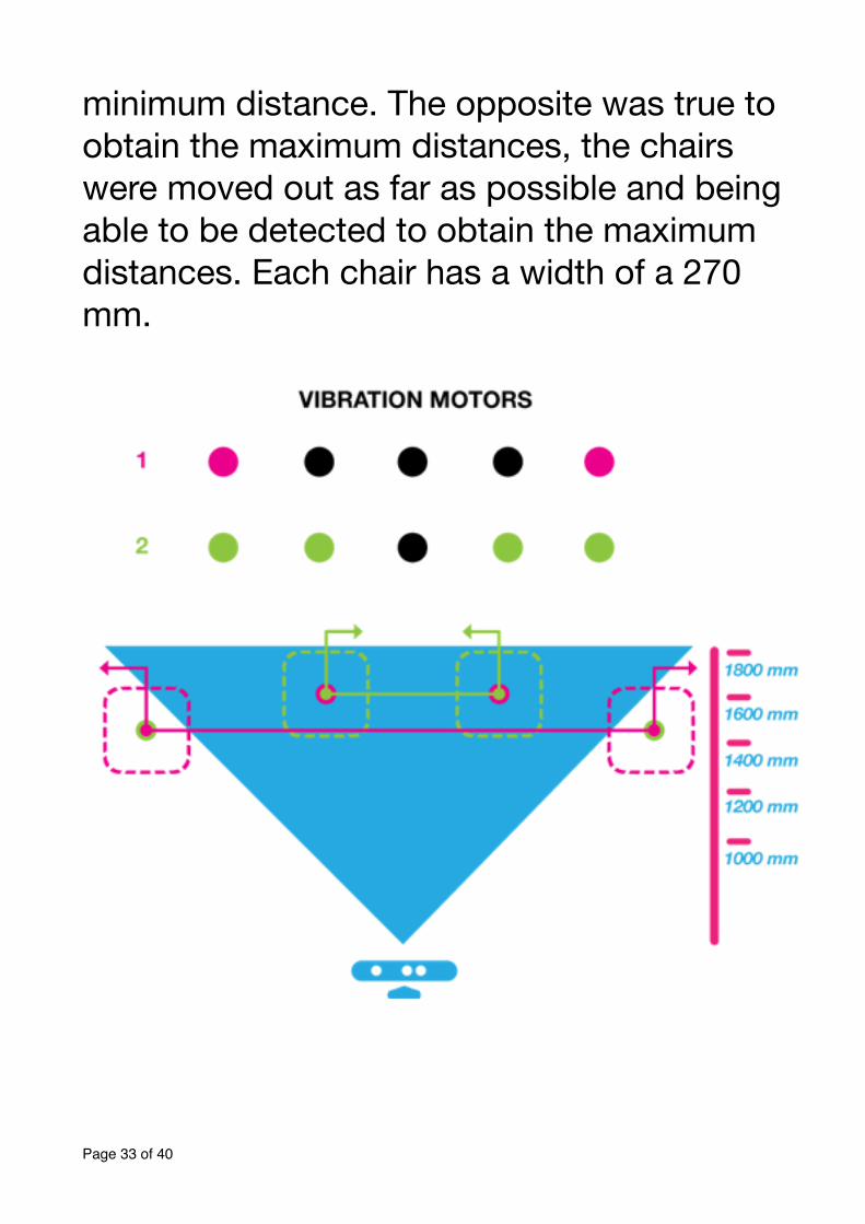
minimum distance. The opposite was true to obtain the maximum distances, the chairs were moved out as far as possible and being able to be detected to obtain the maximum distances. Each chair has a width of a 270 mm.
!
Page � of �33 40
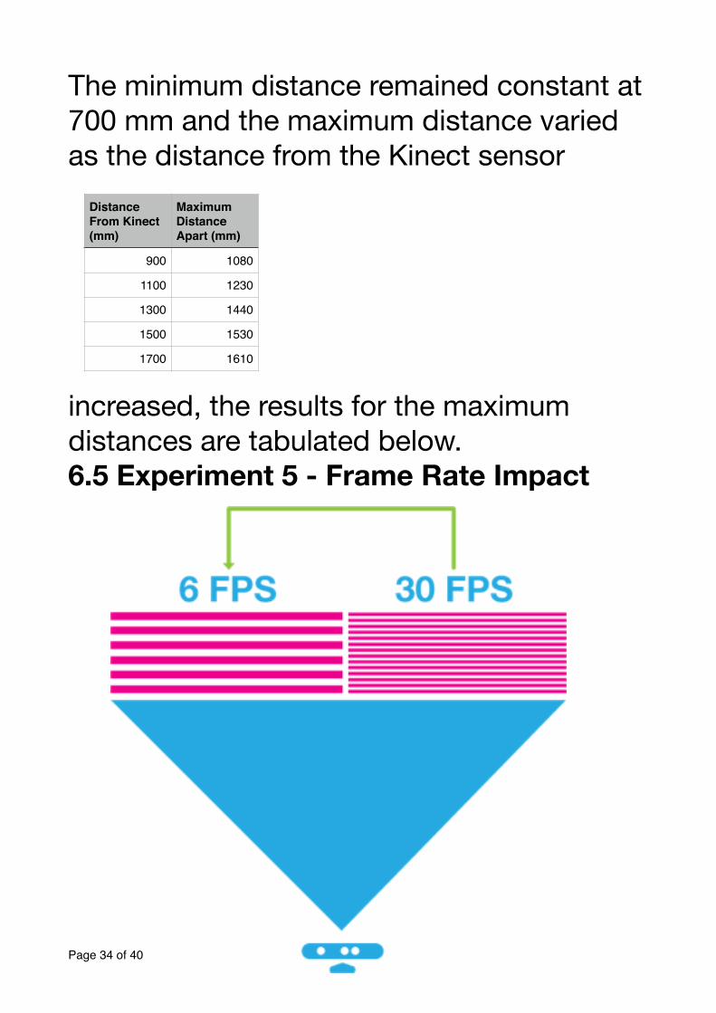
The minimum distance remained constant at 700 mm and the maximum distance varied as the distance from the Kinect sensor
increased, the results for the maximum distances are tabulated below.6.5 Experiment 5 - Frame Rate Impact
Page � of �34 40
Distance From Kinect (mm)
Maximum Distance Apart (mm)
900 1080
1100 1230
1300 1440
1500 1530
1700 1610
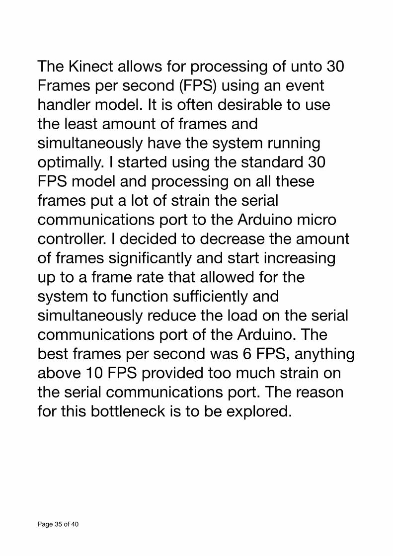
!The Kinect allows for processing of unto 30 Frames per second (FPS) using an event handler model. It is often desirable to use the least amount of frames and simultaneously have the system running optimally. I started using the standard 30 FPS model and processing on all these frames put a lot of strain the serial communications port to the Arduino micro controller. I decided to decrease the amount of frames significantly and start increasing up to a frame rate that allowed for the system to function sufficiently and simultaneously reduce the load on the serial communications port of the Arduino. The best frames per second was 6 FPS, anything above 10 FPS provided too much strain on the serial communications port. The reason for this bottleneck is to be explored.
Page � of �35 40
7. Limitations And Caveats The Kinect does pose a few limitations such as a minimum distance of 80 cm vision at which point anything closer than 80 cm could not be detected. Kinect for PC allows for a near mode which offers a minimum distance of 40 cm. The way in which this is accommodated in the project is to use 90 cm / 900 mm as the new minimum and give the user the opportunity to turn before the Kinect gets to its hardware minimum.!
Page � of �36 40

8. Code Documentation The project code is fully documented and will be stored on a DVD media.!!
Page � of �37 40
Conclusion In chapter 2 we explain the problem statement and the possible solution using technological methods.The user requires a system that they are able to wear that will navigate them around objects in the real world.The final system does take some time to learn to use but after getting used to it one can navigate through the real world. The system does what it was intended to do.
Page � of �38 40
Bibliography !
[1] Kaehler, A., & Bradski, G.,(2008). Learning OpenCV :Computer Vision with the OpenCV Library. United States of America.[2] Jana, A. (2012). Kinect for Windows SDK Programming Guide. United Kingdom: Packt Publishing[3] Karvinen, K., & Karvinen, T.,(2011). Make: Arduino Bots And Gadgets .United States of America: O’reilly Media.[4] EMGU CV Library Documentation. (2012). Retrieved From: http://www.emgu.com/wiki/files/2.4.2/document/Index.html
Page � of �39 40
[5] WHO, Visual Impairment and blindness. (2013, October). Retrieved From: http://www.who.int/mediacentre/factsheets/fs282/en/[6] Mawhorter, P. Vision.py. (2012). Retrieved From: https://svn.cs.hmc.edu/svn/robotics/Summer08/scribbler/slam/vision.py
Page � of �40 40
![Multiple-domain dissociation between impaired visual ... › documents › Bartolomeo1998... · test and the space perception of Visual Object Space Perception Battery [58] correctly,](https://img.pdfslide.us/doc/110x75/5f0375267e708231d409433b/multiple-domain-dissociation-between-impaired-visual-a-documents-a-bartolomeo1998.jpg)