Embed Size (px)
Citation preview
t*-- :1
DEPARTMENT OF CIVIL ENGINEERING & ~lliCHAlJICS
LEHIGH UNIVERSITY
INELASTIC BUCKLING---_.__.......--------_._.-OF ECCENTRICALLY LOADED COLUHNS
May 21, 1953
INTRODUCTIOl'I
Robert L. Ketter
Column type members have been classified in manydifferent waysr however, the distinction usually made isbetween the fo lowing two conditions of loading,
l~ concentric compression, and2. eccentric compression
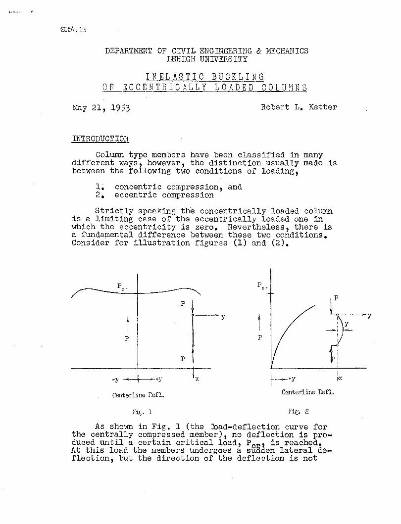
Strictly speaking the concentrically loaded columnis a limiting case of the eccentrically loaded one inwhich the eccentricity is zero. Nevertheless, there isa fundamental difference between these two conditions.Consider for illustration figures (1) and (2).
tp
-y ---+---+y
Centerline r~fl.
Fig. 1
-_.. ""'y
Ix
tp
Il'~+Y
Centerline :D:3f1..
As shown in Fig. 1 (the ~ad-deflection curve forthe centrally compressed member), no deflection is produced until a certain critical load, Pc, is reached.At this load the members undergoes a suaden lateral deflection, but the direction of the deflection is not
Z05Al3 -2-
known in advance. ThiS sUdden movement constitutes theinstability condition discussed in several of the previous talks'ill this series, however, that value of axialthrust, P r' aswas shovrn in seminars (2) and (6), is notnecessarily the maximum load the member will sustain?
If on the other hand, a member is eccentrically compressed as shovrn in Fig. 2, a deflection of unambiguoussign is produced from the start o This condition of predictable -vs.- non~predictable deflections constitutesthe major difference between these seemingly interrelated conditions of loading. The second condition(that of eccentric loading) will not lend itself readilyto the method of inelastic solution as used in the formerproblem since for that case it was only necessary to determine the existance of one equilibrium position otherthan the straight form. The latter case is somewhat moreinvolved since it requires the determination' of two possible adjacent deflected positions satisfying equilibriumof the same loading. .
Before going to the inelastic case it is well that wedetermine the elastic behavior of members loaded eccentrically.
ELASTIC BEHAVIOR
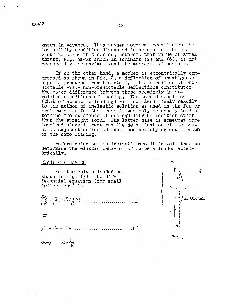
For the column loaded assho,~ in Fig. (3), the differential equation (for smalldeflections) is
dx~ =~ =-P{e,.2.Jfl ••.•.•••..•.••••••••.••••• (l)Illl EI
or
Y'I + k2. r - 1_~- (2)\. :.i - -i\.~ ••••••••••••••••••••••••••••••
p.
I
!~>I• I
I
/:;,-'L I
1 -rV EI COl'JSL..'\HI'J . I_l_.~
pf!I
i'Ix.
where
205A.13
-3-
This equation has the solution
y =ASin kx + BCbs.lx - e
which upon substitution 'of the boundary conditions at x =0 andx = L gives
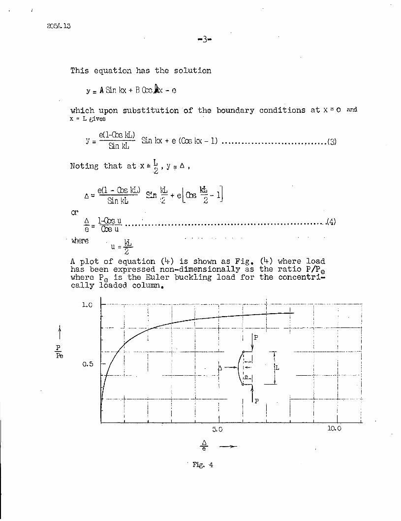
e(l-ebs kL)Y= Sin kL Sin l<x + 8 (Ccs kx -1) ......•..............•... ~ (3)
Noting that atx::.~ , y:;:: 6 ,
_ 8(1 - Cbs kL) ~: kL lrw. ~ 1-\6. - Si kL ::::n ,.- + 8 Un C)-.. n .,::. LJ-
or..!:- _+--<;!.?§.J::!.. • ~ e ••( 4)e- Ca3u
whereu = ~
A plot of equation (4) is shovm as Fig. (4) where loadhas been expressed non-dimensionally as the ratio PIPewhere Pe is the Euler buckling load for the concentrically loaded column.
p
~ _.__ _ -_..-.- .,;-.------..-~-,--.-. _..__.-:-..---'------'··'1"-- _. -·····_·1--·- -,,.,t· .-.._..-. --'- .----_.-.-. ... -,..---.- .. -_._..;-! I 1 - ;! i i
'i, ! I iI: , ,
: , :! ;, I._--j-- ... -'-'f_.... --'" ~ ....-.._-.!--··------+·---·---;----·+-···--1
I •
i iI ! I
·--··~··,,·_I·_·.. ·_··__;·-··, _--L ._;- ..--...---,--.;-----+-- ..- ... --~
! ' l : -1 :--1
1 • I 'I ,
I ' . i
!----.-.-~.--._.--.l~ .._..-:I !
I
I ,\!._. --"';-j- ·--..----·-r....---..-..l..···- ..-. -If-'-----r--..·
! ' ;!
;
,,i
- __...._ ·.. ~i .. _...•_
0.5
1.0
tPFe
5.0 10.0
Fig. 4
'205/'... 13
-1;--
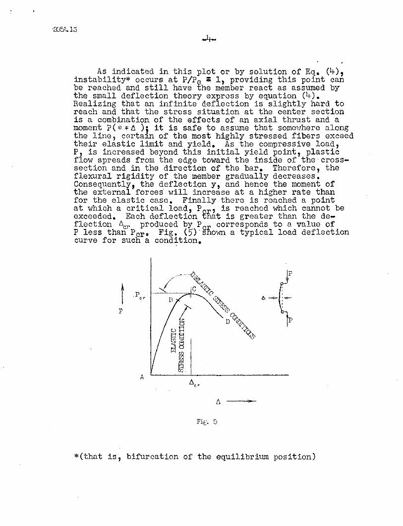
As indicated in this plot or by solution of Eq. (1;-),instability* occurs at P/P~ : 1, providing this point canbe reached and still have the member react as assumed bythe small deflection theory express by equation (4).Realizing that an infinite deflection is slightly hard toreach and that the stress situation at the center sectionis a combination of the effects of an axial thrust and amoment P( e +t1 ) i it is safe to assume that some':lhere alongthe line, certa1n of the most highly stressed fibers exceedtheir elastic limit and yield. As the compressive load,P is increased beyond this initial yield point, plasticflow spreads from the edge toward the inside of the crosssection and in the direction of the bar. Therefore, theflexural rigidity of the member gradually decreases.Consequently, the deflection Y, and hence the moment ofthe external forces will increase at a higher rate thanfor the elastic case. Finally there is reached a pointat which a critical load, Per' is reached which cannot beexceeded. Each deflection ~hat is greater than the deflectio!l ~cr produced by Pcr corresponds to a value ofP less than Per. Fig. (5) "ShOwn a typical load deflectioncurve for such a condition.
p
A
Fi[. 5
*(that is, bifurcation of the equilibrium position)
(Note:
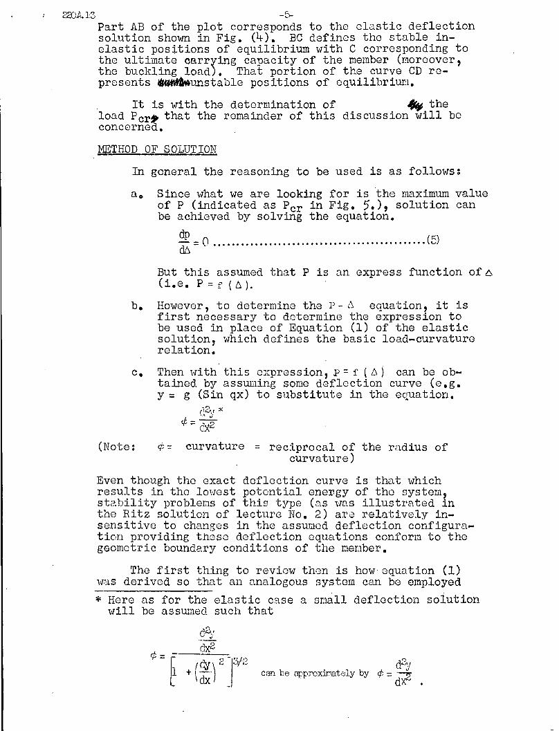
22JA.13 -5-Part AB of the plot corresponds to the elastic deflectionsolution shown in Fig. (4). BC defines the stable inelastic positions of equilibrium with C corresponding tothe ultimate carrying capacity of the member (moreover,the buckling load). That portion of the curve CD represents ~unstable positions of equilibrium.
. It is with the determination of ~ theload Pcr~ that the remainder of this discussion will boconcerned. .
METHOD OF SOLUTION
In general the reasoning to be used is as follows:
a o Since what we are looking for is the maximum valueof P (indicated as Pcr in Fig. 5.), solution canbe achieved by solving the equation.
: =0 •••••••••.•••.•••••.••• ; •.••••.•.••.•.••.••.•• (5)
But this assumed that P is an express function Of6(i.e. P=f (~).
b. HowGver, to determine the p-l\~ equation, it isfirst necessary to dotermine the expression tobe used in place of Equation (1) of the elasticsolution, which defines the basic load-curvaturerelation.
c. Then \vith this expression, P = f ( !::.) can be obtained by assUllling somo deflection curve (e.g.y = g (Sin qx) to substitute in the equation.
([2'1 ;j(
¢ =dJ.2¢ = curvature = reciprocal of the radius of
curvature)
Even though the exact deflection curve is that whichresults in the lowest potential energy of the system,stability problems of this type (ns vlaS illustrated inthe Ritz solution of lecture No.2) are relatively insensitive to changes in the assumod deflection configuration providing those deflection equations conform to thegeometric boundary conditions of tho member.
The first thing to review thon is how equation (1)was derived so that an analogous system can be employed
* Here as for the elastic case a small deflection solutionvIill be assumed such that
can be approxir:.ately by
-6-
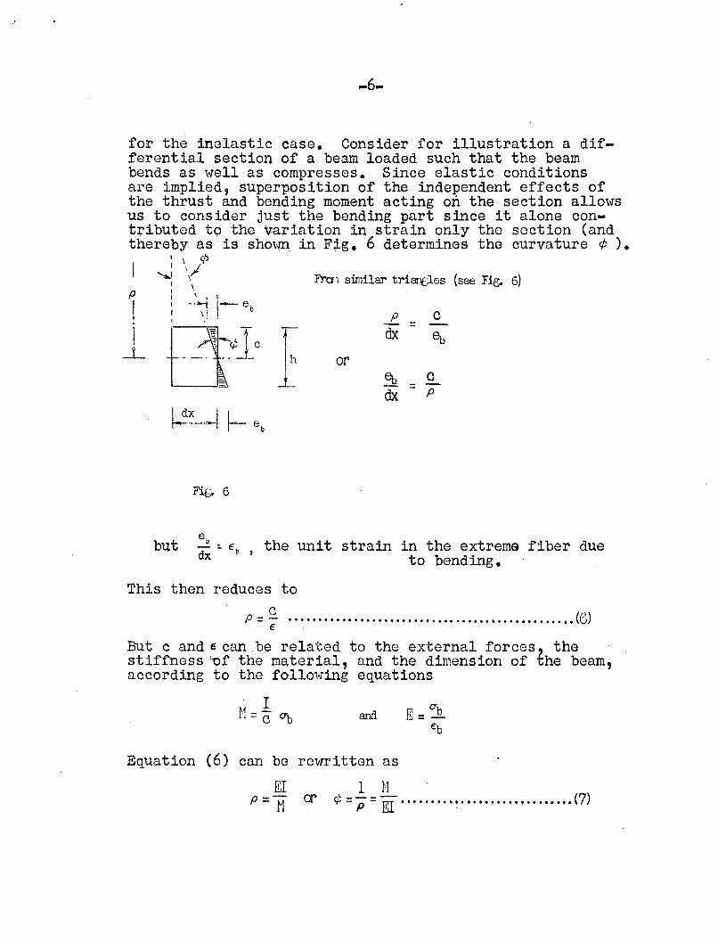
c=p
dx
~ = cdx p
or
F'Tcr1 similar triarlfJes (see Fig. 6)
rIh
J....
for the inelastic case. Consider for illustration a differential section of a beam loaded such that the beambends as well as compresses. Since elastic conditionsare implied, superposition of the independent effects ofthe thrust and bending moment acting on the section allowsus to consider just the bending part since it alone contributed to the variation in strain only the section (andthereby as is shovm in F~g. 6 determines the curvature ¢ ).
I \ ¢
~: '/: \
: _.~-1 1
1- e.
I \ I 0I
p
II
-L
Fi.g~ 6
but eo- ::: € , the unit strain in the extrema fiber duedx b to bending.
This then reduces to
p =~ .. ~ .•....... ·.~ ..•............•........••....... (6)
But c and E can .be related to the external forces thestiffness 'of the material, and the dimension of the beam,according to the folloWing equations
. IH=cOb and
Equation (6) can be rewritten as
1 11¢ =Ii = EI ••••••••• ~ ••••• • •••••.• • •••••• (7)
'aJflt\.• 13
-7-
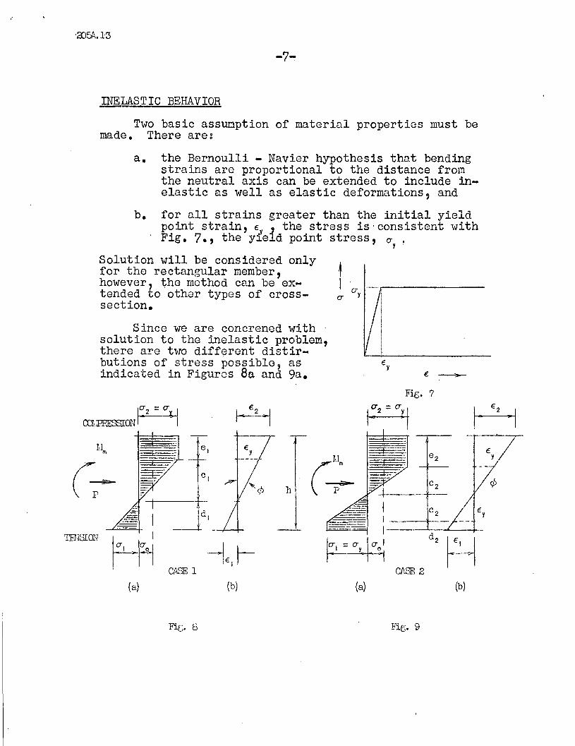
INELASTIC BEHAVIOR
Two basic assunption of material properties must bemade. There are:
a. the Bernoulli - Navier hypothesis that bendingstrains are proportional to the distance fromthe neutral axis can be extended to include inelastic as well as elastic deformations, and
~-
Since we are concrened withsolution to the inelastic problem,there are two different distirbutions of stress possible, asindicated in Figures 8a and 9a.
b. for all strains greater than the initial yieldpoint strain,S i the stress is 'consistent withFig. 7., the y~e d point stress, O'y ~
Solution will be considered onlyfor the rectangular member,however, the mothod can be extended to other types of crosssection.
Fie;. 7
10'2 = 5:JCOLPRESSIONr -I
1~2 =Cir1
€y
.~
=r=====:E'"-
:7i c 2-~---_. '---
~ !--=:£- -- €,
~~~ d, ~~1CfI.8E 2
--
(/~
P
TENSWN
(a) (b) (a) (b)
CD5L13 --8-
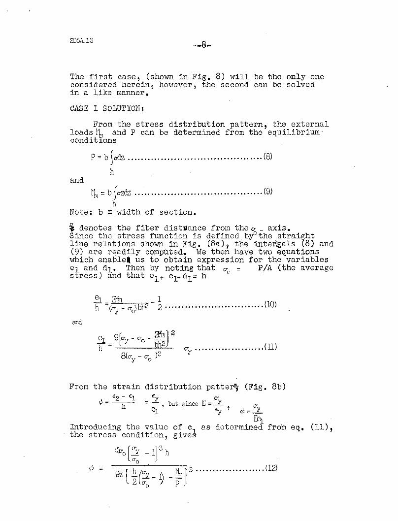
The first case, (shovffi in Fig. 8) will be the only oneconsidered herein, however, the second can be solvedin a like manner.
CASE 1 SOLUTION:
From the stress distribution pattern, the externalloads rb and P can be determined from the equilibrium"conditlons
P=b iodz .•...••..•••.•.........••.•••••..•••.•.•. (8)
hand
tl'1 =b fazdz •••••••••..••.••.••••.•••••••••••••• , •• (9)
hNote: b =width of section.
'i denotes the fiber dist»ance from the CT _ axis.Since tho stress function is defined,byOthe straightline relations Shovffi in Fig. (Ba), the inter~als (8) and(9) n.re readily computed. We then have two equationswhich enable. us to obtain expression for the variablesel and dl. Thon by noting that O"c_ = PIA (tho avoragestress) and that el + cl+ dl = h '
81 3m 111 ::z (O"y - ;-0) bh2 - 2 (10)
and
CJ. grCT,,r - 0"0 - 3!.m1 2
-h = l oJ bh2J , (11)O"~r •••••••••••••••••••••
8(o-y - 0"0 )3
eq. (11),
(Fig. 8b)
O:y'("1, _r'--
[~1 'o~ c, as dotermined fromglves
Introducing the valuethe stress condition,
:4:0 l' cr:'J - i13 h0"0 "
From the strain distribution patter~
E2 - €1 Ey CT.~-= - b . ~I' Y'f' --, ut Slnce J.:J =_
h C:J. €y ?
\~ ~ 9E [ h(L ~ _lq2 (l2)
2 0"0 P .
2fJ5A.13
-9-
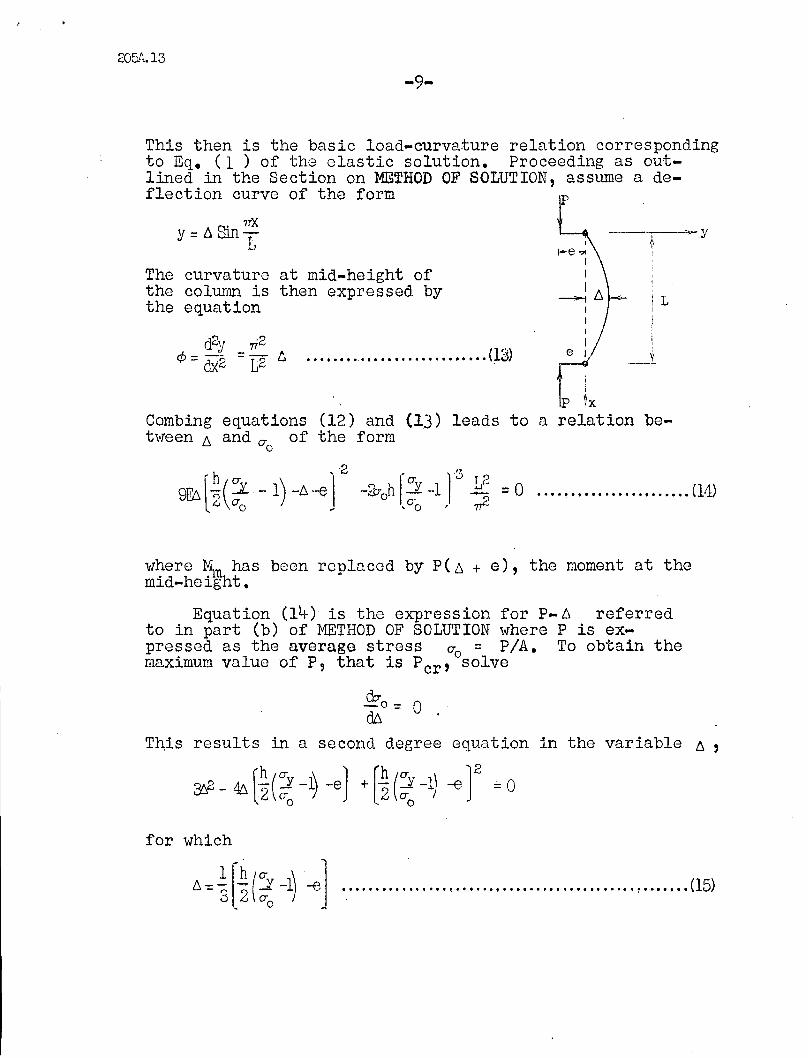
I-e"",III----. /). I"
- I i L, I
II
Ie I
tp t(13) leads to a relation be-
••••••., e,' •••••••••••••••• •• (13)
Combing equations (12) andt",reen /). and er of the form
o
The curvature at mid-height ofthe colunm is then expressed bythe equation
This then is the basic load-curvature relation correspondingto Eq. (1 ) of the elastic solution. Proceeding as outlined in the Section on METHOD OF SOLUTION, assume a deflection curve of the form
S. 7TX
y=/). lilT
where ~n has been replaced by P(6 + e), the moment at themid-height.
Equation (14-) is the expression for P- 6 referredto in part (b) of METHOD OF SOLUTION where P is expressed as the average stress 0'0 = PIA. To obtain themaximum value of P, that is Pcr ' solve
do-_0 = 0d6
This results in a second degree equation in the variable 6 ,
~2 _46 r.~(ery -1) -8] + rh (5' -1) -e'12:i:: 0l2 ero ,2 ero _
for which
l\=~[~(:~ -1) -€] (15)
205A.13-10-
SUbstituting eq. (15) in eq~ (14) and rearranging termsgives
·30: .;£
y -1- -~ h
O:y- -1 (16)O:c
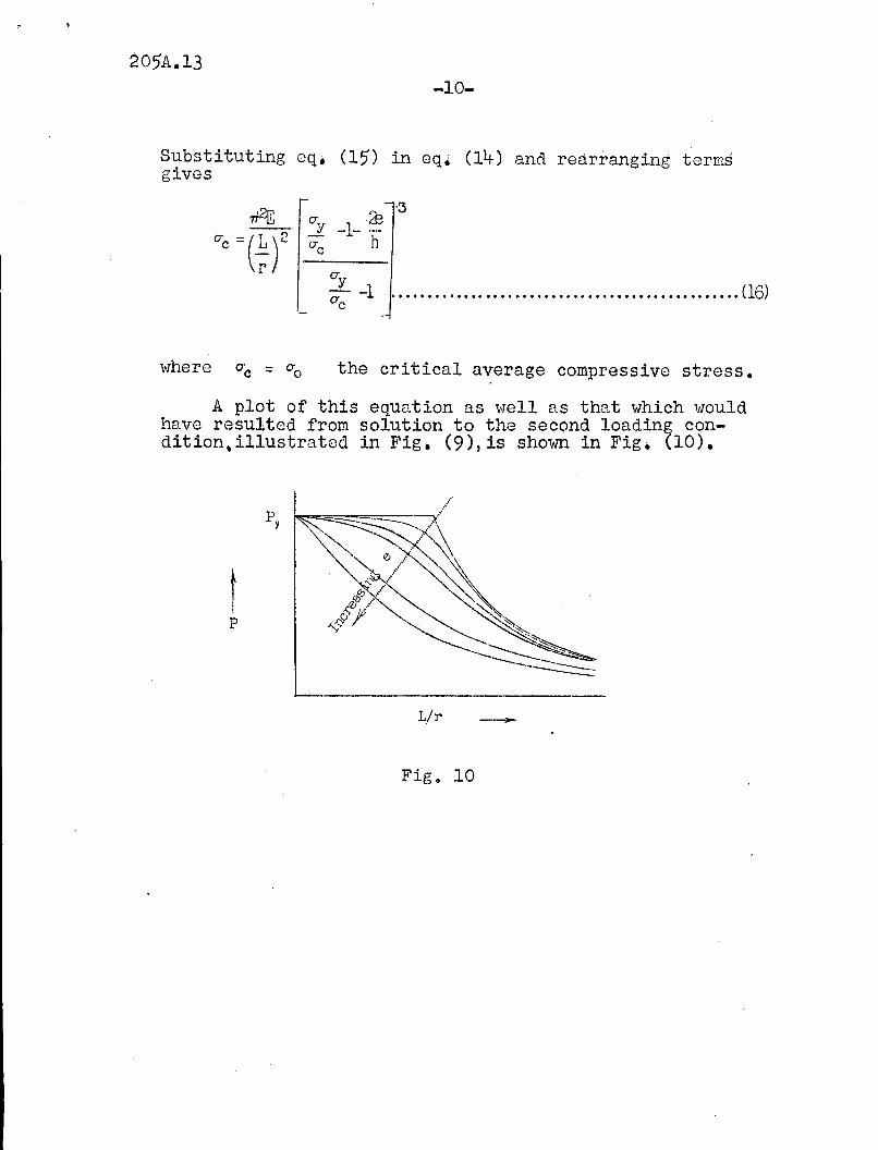
the critical average compressive stress.
A plot of this equation as well as that which wouldhave resulted from solution to the second loading condition,illustrated in Fig. (9),is shown in Fig. (10).
Ip
py
LIT'
Fig o 10
205A.13-11-
Bleich, F., "Buckling Strength of Hetal Structures",McGraw-Hill Book Co., New York, 1952. .
Wastlund, George, and Bergstrom, Sven G., "Bucklingof Compressed Steel Members", Transactions of theRoyal Institute of Technology, Stockholm, Swaden,1949.
4.
5.
Timoshenko, S'" "Theory of Elastic Stability", McGrawHill Book Co., New York, 1936.
Jezek, K., "Die Tragftlhigkeit des gleichma~ig
querbelasteten Druckstabes auseinem ideal-plastischenStahl", Der Bautechnil{, Vol. 5, p. 33, 1935.
Shook, C.~ "Buckling of Beams-Exact Solution, EnergyMethod", ~second seminar - Dept. of CiJE o & Mech.,Lehigh, 1953).
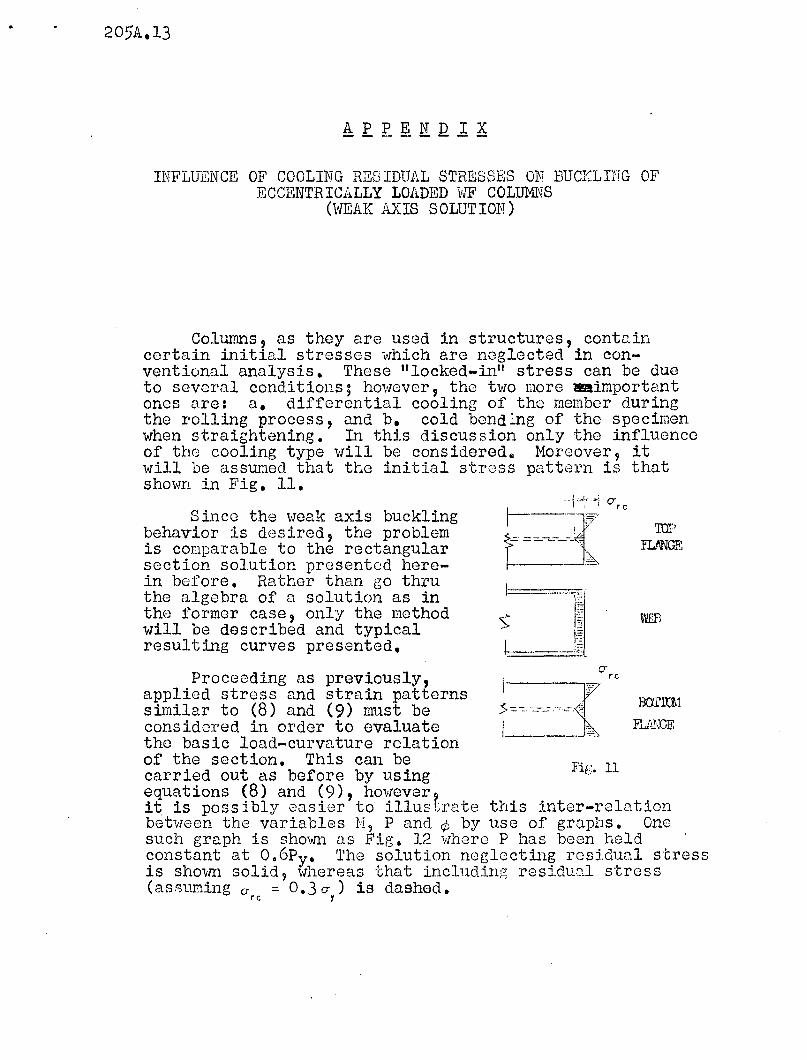
INFLUENCE OF' COOLING RES IDUAL STRESSES ON BUC:r=LIFG OFECCENTRICALLY LOADED VW COLUMNS
(WEAK AXIS SOLUTION)
Columns, as they are used in structures, containcertain initial stresses which are noglected in conventional analysis. These "locked-in" stress can be dueto several conditions; however, the t\VO more _importantones are: a. differential cooling of the member duringthe rolling process, and b. cold bend:ng of the specimenwhen straightening. In this discussion only the influenceof tho cooling type will be considered. Moreover, itwill be assumed that the initial stross pattern is thatshown in Fig. 11.
wrn
TOPFLANGE
Since the weak axis bucklingbehavior is desired, the problemis comparable to the rectangularsection solution presented herein before. Rather than go thruthe algebra of a solution as inthe former case, only the methodwill be described and typicalresulting curves presented.
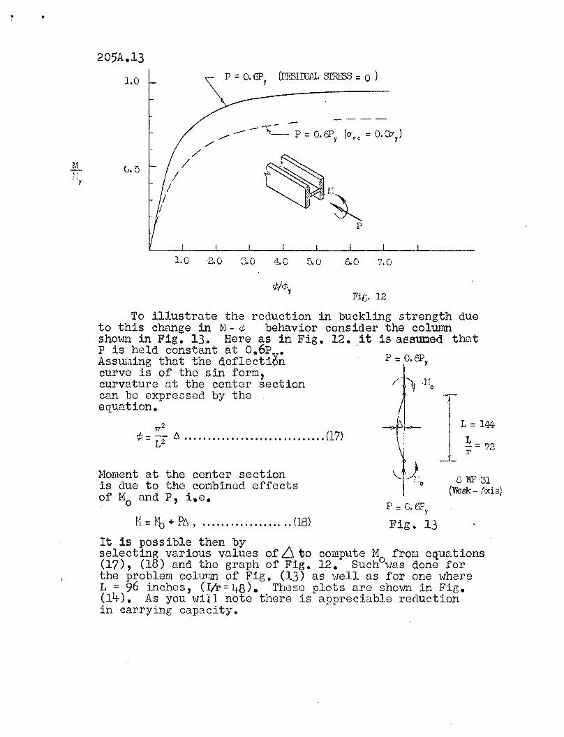
Proceeding as preViously,applied stress and strain patternssimilar to (8) and (9) must beconsidered in order to evaluatetho basic load-curvature relationof the section. This can becarried out as before by usingequations (8) and (9), however?it is possibly easier to illustrate this inter-relationbetween the variables M, P and ¢ by use of graphs. Onesuch graph is shown as Fig. 12 where P has been holdconstant at 0.6py• 'rho solution noglecting ros5.o.ual stressis shovm solid, '''heroas that inclUding resi.dual stress(assuming a = 0.3 u ) is dashed.
rc y
" .
1.0 p =O. 6P (PFBlIUAL SIRESS = 0 )y
~I~P
Ml' '~11
Y
0.5
...,--
....- --- - 'It__ P =0.6I\ (ITre =O.-::O-y)./
//
/I
/I
1.0 -2.0 3.0 4.0 5.0 6.0 7.0
A./cf;'+1'. Y
Fi[;. 12
L = 14.4
~= 79r .~
7T2
¢=L"z6.······· .. ··· .. ·.. ·· .. ·········(17)
To illustrate the reduction in buckling strength dueto this change in M - ¢ behavior consider the colunmshown in Fig. 130 Here as in Fig. 12. it is assuned thatP is held constant at o.6p •AssuEling that the deflecti6ncurve is of the sin form,curvature at the center sectioncan be expressed by theequation.
8 WF31(Vle8k - iuds)
\.11
,;'0
p =o.6F'y
Fig. 13
Moment at the center sectionis due to the combined effectsof Mo and P, i.e.
I·I = ~b + PL\, (18)
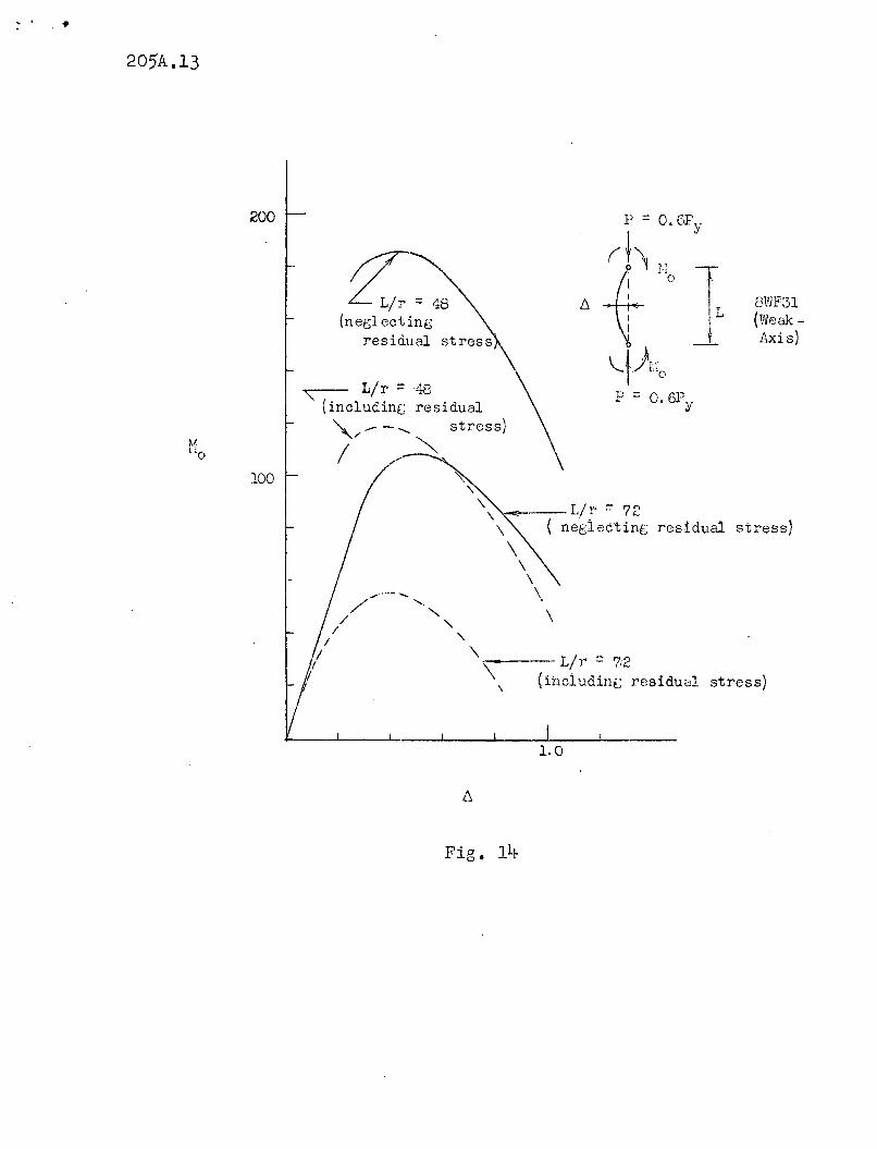
It is possible then byselecting various values of 6. to compute M from equations(17), (18) and the graph of Fig. 12. Suchowas done forthe problem colunm of Fig. (13) as well as for one wher~L = 96 inches, (I/r = 48) 0 T~8se plots are shown in Fig.(14). As you will note there is appreciable reductionin carrying capacity.
205A.13
8WF31(Weak Axis)
( neglecting residual stress)
\
L/r = 48{net;lecting
residual
.".' ,.,.- "-/ '-.
/ ""-/ "-
/ "-/ "-
/ -\---- L/ r' =: 7:2(ihcludint; residual stress)
L/r =48
" (includin[; residual". __ -........ stress)
~/ "'"/ --
200
100
1.0
Fig. 14