Embed Size (px)
Citation preview
DENVER AMENDMENT PROPOSAL 2015 INTERNATIONAL CODES
UPDATED DEADLINE: JANUARY 9, 2015
NOTE: Each proposed Denver amendment to the International Codes must be justified. In order to be considered, the amendment proposal must address climate, clarity and/or cost.
1) Submitter Information
Name: David Renn, PE Date: 1/8/2015 Rev. 6/16/2015
Organization (if applicable):
Structural Engineers Association of Colorado (SEAC)
Phone: 720‐865‐2813 E‐mail address:
2) *Signature: * I hereby grant and assign to City and County of Denver all rights in copyright I may have in any authorship contributions I make to City and County of Denver in connection with this proposal. I understand that I will have no rights in any City and County of Denver publications that use such contributions in the form submitted by me or another similar form and certify that such contributions are not protected by the copyright of any other person or entity. Note: electronic signatures are acceptable.
3) Indicate which International Code (I‐Code) you propose to amend (please use acronym): IBC
If your code proposal requires an amendment to another I‐Code, please indicate which other I‐Code and section(s) is impacted, and provide the necessary language within the proposal form. See section below for list of names and acronyms for the International Codes.
4) Be sure to format your proposal and include all information as indicated on pages 2‐3 of this form.
5) Send your proposal to Community Planning and Development (CPD), attention: Jill Jennings Golich, via email at [email protected]. An e‐mail submittal should include an electronic version saved with a file name as follows: 2015_public_amendment_proposal_Codname_SectionReference, where ‘Codename_SectionReference’ is replaced using the code and section being proposed (for instance ‘2015_public_amendmnet_proposal_IBC_Section312’). The only formatting necessary is BOLDING, STRIKEOUT AND UNDERLINING. Please do not provide additional formatting such as this will be done by CPD.
Please use a separate form for each proposal submitted unless as allowed in 3) above. Note: All amendment proposals received will receive an acknowledgment, and will be posted on the Building Code website to allow the public review. Please check here if a separate graphic file is provided. X□ Graphic materials (graphs, maps, drawings, charts, photographs, etc.) must be submitted as separate electronic files in either PDF, JPEG or TIF format (300 DPI minimum resolution; 600 DPI or more preferred) even though they may also be embedded in your submittal.
Acronym Code Name DBC‐AP Denver Building Code–Administrative
Provisions IBC International Building Code IECC International Energy Conservation Code IEBC International Existing Building Code IFC International Fire Code IFGC International Fuel Gas Code IMC International Mechanical Code
Acronym Code Name IPC International Plumbing Code IRC International Residential Code NEC National Electrical Code
AMENDMENT PROPOSAL Please provide all of the following items in your amendment proposal. Your proposal may be entered on the following form, or you may attach a separate file. However, please read the instructions for each part of the amendment proposal.
Code Sections/Tables/Figures Proposed for Revision:Note: If the proposal is for a new section, indicate (new). 1608.1 and 1608.2 (2011 Denver amendments), 1608.4 (previously 1608.3 in 2011 Denver amendments) and new 1608.5.
Proposal: Show the proposal using strikeout or underline format. At the beginning of each section, include one of the following instruction lines: •Revise as follows •Add new text as follows •Delete and substitute as follows •Delete without substitution Revise Denver amendments to 1608.1, 1608.2 and 1608.4, and add 1608.5, as follows:
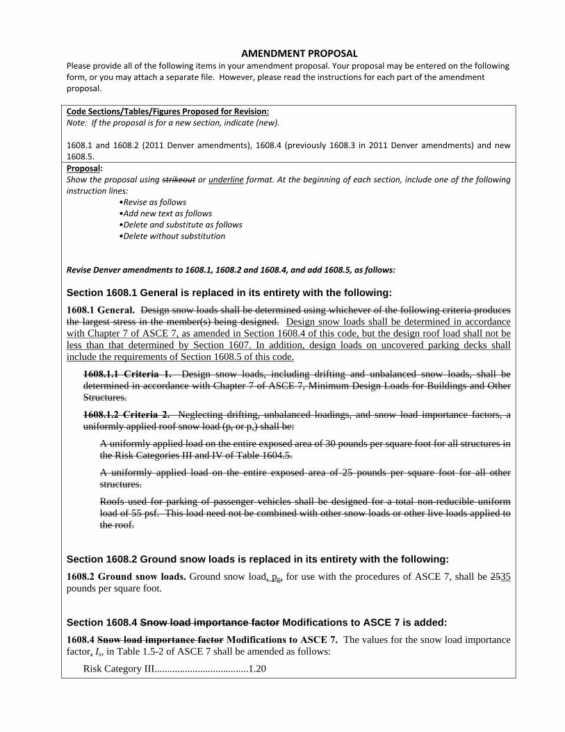
Section 1608.1 General is replaced in its entirety with the following:
1608.1 General. Design snow loads shall be determined using whichever of the following criteria produces the largest stress in the member(s) being designed. Design snow loads shall be determined in accordance with Chapter 7 of ASCE 7, as amended in Section 1608.4 of this code, but the design roof load shall not be less than that determined by Section 1607. In addition, design loads on uncovered parking decks shall include the requirements of Section 1608.5 of this code.
1608.1.1 Criteria 1. Design snow loads, including drifting and unbalanced snow loads, shall be determined in accordance with Chapter 7 of ASCE 7, Minimum Design Loads for Buildings and Other Structures.
1608.1.2 Criteria 2. Neglecting drifting, unbalanced loadings, and snow load importance factors, a uniformly applied roof snow load (pf or ps) shall be:
A uniformly applied load on the entire exposed area of 30 pounds per square foot for all structures in the Risk Categories III and IV of Table 1604.5.
A uniformly applied load on the entire exposed area of 25 pounds per square foot for all other structures.
Roofs used for parking of passenger vehicles shall be designed for a total non-reducible uniform load of 55 psf. This load need not be combined with other snow loads or other live loads applied to the roof.
Section 1608.2 Ground snow loads is replaced in its entirety with the following:
1608.2 Ground snow loads. Ground snow load, pg, for use with the procedures of ASCE 7, shall be 2535 pounds per square foot.
Section 1608.4 Snow load importance factor Modifications to ASCE 7 is added:
1608.4 Snow load importance factor Modifications to ASCE 7. The values for the snow load importance factor, Is, in Table 1.5-2 of ASCE 7 shall be amended as follows:
Risk Category III.....................................1.20

Risk Category IV.....................................1.40
Section 1608.5 Snow load on uncovered parking decks is added:
1608.5 Snow load on uncovered parking decks. Uncovered decks used for parking of passenger vehicles shall be designed for a non-reducible uniformly applied design load of 55 psf. This load includes the combined effects of snow and live loads, and need not be combined with other snow loads or other live loads applied to the parking deck.
Supporting Information: The following items are required to be included. Purpose: The proponent shall clearly state the purpose of the proposed amendment to climate and/or clarify that are specific to
the City and County of Denver (e.g., clarify the Code; revise outdated material; substitute new or revised material for physical, environmental and customary characteristics; add new requirements to the Code; delete current requirements, etc to reflect physical, environmental and customary characteristics that are specific to the City and County of Denver.) Revise snow loads to reflect the snow loads currently recommended by SEAC for the City and County of Denver. Reasons: The proponent shall justify changing the current Code provisions, stating why the proposal is necessary to reflect physical, environmental and customary characteristics that are specific to the City and County of Denver. Proposals that add or delete requirements shall be supported by a logical explanation which clearly shows why the current does not reflect physical, environmental and customary characteristics that are specific to the City and County of Denver and explains how such proposals will improve the Code. This proposed amendment is necessary to reflect environmental characteristics specific to the City and County of Denver. The 2011 Denver Amendments currently include recommendations from SEAC including the following: minimum uniform roof snow load of 30 psf for high risk buildings (Category III and IV) and 25 psf for other buildings; drifting and unbalanced snow load provisions in ASCE 7 using a ground snow load of 25 psf for all buildings, and increased importance factors for Category III and IV buildings when using ASCE 7 provisions. The SEAC Snow Load Committee is currently finalizing a 2015 report titled “Colorado Design Snow Loads”, which revises SEAC’s 2007 report titled “Colorado Ground Snow Loads”. A ballot copy of this report was recently provided to SEAC’s membership to review and to vote on endorsement of this report. At a SEAC general meeting on May 28, 2015, the SEAC membership unanimously voted to endorse this report. As a result of this vote, SEAC is proposing this amendment to revise Denver’s snow load requirements to reflect the recommendations in this report, as described below. The previous design ground snow loads were based on a statistical analysis using a uniform hazard approach (i.e. the snow load that occurs on average every 50 years). However, new studies conducted by the SEAC Snow Load Committee have shown that using the 50‐year load does not provide uniform protection against the risk of roof failure, meaning the probability of failure may be higher than expected. The new design snow loads are based on a uniform risk approach instead of a uniform hazard approach to provide the reliability levels targeted by the national standard ASCE 7. As a result of this new approach, the design ground snow is proposed to be increased to 35 psf for use in the ASCE 7 snow load provisions. The ASCE 7 procedures will then result in a uniform roof design snow load of 25 psf for most (typical) buildings (i.e. Risk Categories I and II), and a uniform roof design snow load of 30 psf for buildings in Risk Category III, which are the same as the current uniform snow load requirements for these same Risk Categories. The uniform roof design snow load for Risk Category IV will increase from 30 psf to 35 psf. Since the ASCE procedures result in essentially the same uniform snow loads as previously required by the Denver amendments, the uniform snow load cases are no longer required in the amendments. The new SEAC report recommends increased importance factors for Category III and IV buildings that are in line with the current Denver amendments, and this amendment proposal retains these increased factors. Substantiation: The proponent shall substantiate the proposed amendment based on technical information and substantiation. Substantiation provided which is reviewed and determined as not germane to the technical issues addressed in the proposed amendment shall be identified as such. The proponent shall be notified if the proposal is considered an incomplete proposal, and the proposal shall be held until the deficiencies are corrected. The burden of providing substantiating material lies with the proponent of the amendment proposal. A minimum of two copies of all substantiating information shall be submitted. Excerpts from the 2015 “Colorado Design Snow Loads” report are attached. Bibliography: The proponent shall submit a bibliography when substantiating material is associated with the amendment proposal. The proponent shall make the substantiating materials available for review. “Colorado Design Snow Loads”, Structural Engineers Association of Colorado, 2015
Referenced Standards: List any new referenced standards that are proposed to be referenced in the code and provide a minimum of one electronic copy. Should the amendment proposal be recommended for inclusion in the amendment package, you must provide two hard copies. No new referenced standards proposed.
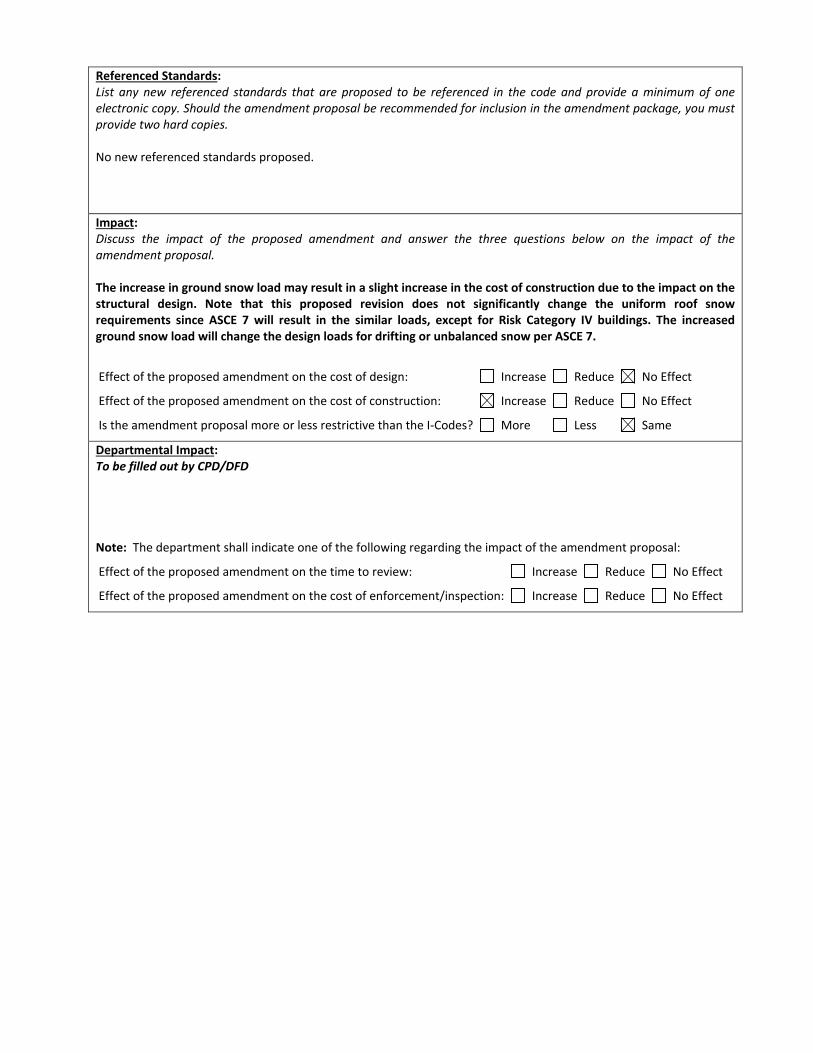
Impact: Discuss the impact of the proposed amendment and answer the three questions below on the impact of the amendment proposal. The increase in ground snow load may result in a slight increase in the cost of construction due to the impact on the structural design. Note that this proposed revision does not significantly change the uniform roof snow requirements since ASCE 7 will result in the similar loads, except for Risk Category IV buildings. The increased ground snow load will change the design loads for drifting or unbalanced snow per ASCE 7.
Effect of the proposed amendment on the cost of design: Increase Reduce No Effect
Effect of the proposed amendment on the cost of construction: Increase Reduce No Effect
Is the amendment proposal more or less restrictive than the I‐Codes? More Less Same
Departmental Impact: To be filled out by CPD/DFD Note: The department shall indicate one of the following regarding the impact of the amendment proposal:
Effect of the proposed amendment on the time to review: Increase Reduce No Effect
Effect of the proposed amendment on the cost of enforcement/inspection: Increase Reduce No Effect
2015
Prepared by the Structural
Engineers Association of
Colorado (SEAC)
Colorado Design Snow Loads
Colorado Design Snow Loads BALLOT COPY NOT APPROVED FOR FINAL USE i
Colorado Design Snow Loads Structural Engineers Association of Colorado
Prepared By
The SEAC Snow Load Committee
D. Jared DeBock James Harris
Abbie Liel Jeannette Torrents, Chair
May 2015
© Copyright 2015 by the Structural Engineers Association of Colorado
Colorado Design Snow Loads BALLOT COPY NOT APPROVED FOR FINAL USE ii
Executive Summary
The Structural Engineers Association of Colorado (SEAC) Snow Load Committee has developed
new ground snow loads to be used for structural design in Colorado. Philosophically, these loads
represent a transition from a uniform hazard approach to a uniform risk approach for determining
design snow loads. Previous loads, including those in the 2007 SEAC report, determine design
ground snow loads based on a uniform hazard, i.e. the design value at a site is taken as the snow
load that occurs, on average, once every 50 years (in other words, the mean recurrence interval is
50 years). However, due to the large variations in climate throughout Colorado, new studies
conducted by this committee have shown that using the 50-year load as the basis for design does
not provide uniform protection against the risk of roof failure. In particular, at plains sites, roof
design based on the 50-year ground snow load may not achieve the reliability levels targeted by
national (ASCE-7) standards, meaning that the probability of failure may be higher than
expected. The converse is true in mountainous regions, where the reliability achieved when the
50-year load is used in design may actually be greater than required by ASCE-7. These patterns
stem from differences in snowfall and accumulation throughout the state. In the mountains, snow
builds up over the course of the winter producing large ground loads, but many of those sites
exhibit fairly low variability in the loads from year to year. Snow loads in the plains tend to be
dependent on large single-storm events, and they are highly variable from year to year.
The computation of loads for a target risk of failure results in loads appropriate for strength-
based structural design. However, for convenience of use with ASCE 7, the loads presented in
this report have been divided by the load factor (1.6) prescribed for snow loads in ASCE 7. Thus
the loads are also appropriate for use with allowable stress design methods and for serviceability
checks.
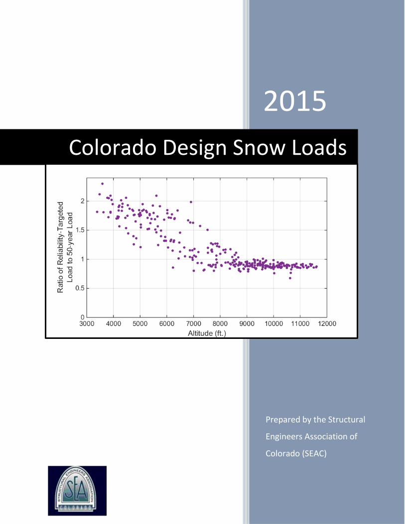
Compared to the 2007 recommended loads, there have been small decreases in design loads in
the mountains (approximately 10%), and increases in design loads in the plains (approximately
50%-100%). The increase in the design loads in the plains is consistent with historic and current
practice, where design roof loads of 20 to 30 psf have typically been used. A number of other
improvements have been made. First, the new analysis utilizes approximately seven additional
years of weather data generated since the development of the 2007 map. In addition, improved
relationships for snow depth and snow weight have been used. Third, a method of using all the
data for large regions of the state to better predict rare events has been used. Finally, reliability
targeted loads have been computed from available data at over 300 sites. These loads have been
correlated with the altitude of the site and maps have been produced that provide parameters to
compute the ground snow load given the altitude of the site. The mapping process introduces a
geographic smoothing, or averaging, on top of the reliability-targeted loads, which smoothens
some of “noise” inherent in the historical record. The recommended design loads are those that
come out of the mapping process.
This report provides detailed documentation of: (a) new mapped values, including comparison to
previously used values, (b) the snow load and depth data used in the development of the maps,
and (c) probabilistic approaches used to evaluate roof reliability and conduct spatial smoothing.
The report also provides recommendations for use of these loads with ASCE 7 and for future
improvements.
Colorado Design Snow Loads BALLOT COPY NOT APPROVED FOR FINAL USE iii
Table of Contents
EXECUTIVE SUMMARY ........................................................................................................................................... II
TABLE OF CONTENTS ............................................................................................................................................. III
PART 1. 2015 DESIGN SNOW LOAD MAPS .............................................................................................................. 1
1.1. INTRODUCTION AND MOTIVATION .............................................................................................................................. 1 1.1.1. The Need for a Revised Design Snow Load Recommendations and a New Map ....................................... 1 1.1.2. Objective of New Reliability-Based Design Snow Loads ............................................................................. 1
1.2. RECOMMENDED DESIGN SNOW LOADS FOR COLORADO ................................................................................................. 2 1.2.1. Basis for Use ............................................................................................................................................... 2 1.2.2. Design Snow Loads ..................................................................................................................................... 2 1.2.3. Additional Recommendations .................................................................................................................. 12
1.3. FUTURE WORK ..................................................................................................................................................... 13
PART 2. DEVELOPMENT OF 2015 DESIGN SNOW LOAD MAPS FOR COLORADO ................................................... 14
2.1. DATA ACQUISITION AND PROCESSING ........................................................................................................................ 14 2.1.1. Data Sources ............................................................................................................................................ 14 2.1.2. Initial Data Processing .............................................................................................................................. 15
2.2. METHODOLOGY TO COMPUTE RELIABILITY-TARGETED GROUND SNOW LOADS ................................................................. 16 2.2.1. Test Structure Design ............................................................................................................................... 16 2.2.2. Reliability Analysis Overview .................................................................................................................... 16 2.2.3. Uncertain Demand Variables ................................................................................................................... 17 2.2.4. Uncertain Capacity Variables ................................................................................................................... 18 2.2.5. Example Reliability Assessments .............................................................................................................. 18
2.3. MAPPING RELIABILITY-TARGETED GROUND SNOW LOADS ............................................................................................ 22 2.3.1. Overview .................................................................................................................................................. 22 2.3.2. Importance of Correlations of Snow Loads with Altitude ......................................................................... 23 2.3.3. Correlations of Snow Loads with Altitude ................................................................................................ 24 2.3.4. Methods for Mapping the Parameter K ................................................................................................... 25 2.3.5. Expert Judgment....................................................................................................................................... 25 2.3.6. Evaluation of the Proposed Snow Map .................................................................................................... 26
2.4. COMPARISONS OF 2015 RECOMMENDED LOADS WITH PREVIOUS PROVISIONS ................................................................. 27 2.4.1. Comparison of Reliability-Targeted Design Ground Snow Loads to 50-year Ground Snow Loads ........... 27 2.4.2. Comparison with Prior SEAC Recommendations ...................................................................................... 28
2.5. WORKS CITED ...................................................................................................................................................... 30
APPENDIX 1. DEVELOPMENT OF CONVERSIONS BETWEEN SNOW DEPTH AND SNOW WEIGHT ........................... 31
A1.1. INTRODUCTION................................................................................................................................................... 31 A1.2. COMPACTED SNOW AND SETTLED SNOW ................................................................................................................ 31 A1.3. COMPACTED SNOW SITES ..................................................................................................................................... 31 A1.4. SETTLED SNOW SITES .......................................................................................................................................... 32 A1.5. INTERMEDIATE SNOW SITES .................................................................................................................................. 33 A1.6. TREATMENT OF UNCERTAINTY/VARIABILITY IN THE DEPTH-TO-WEIGHT CONVERSIONS .................................................... 34 A1.7. WORKS CITED .................................................................................................................................................... 35
APPENDIX 2. DEVELOPMENT OF GROUND TO ROOF WEIGHT CONVERSION FOR MONTE CARLO SIMULATION ... 36
A2.1. INTRODUCTION................................................................................................................................................... 36 A2.2. ROOF AND SNOW LOADS DATA SET........................................................................................................................ 36 A2.3. FITTING THE PROBABILISTIC MODEL ....................................................................................................................... 37
A2.3.1. Step 1: Non-parametric Characterization of the Ground-to-Roof Snow Weight Conversion ................. 37 A2.3.2. Step 2: Fitting the Analytical Ground-to-Roof Snow Weight Conversion Model .................................... 38
Colorado Design Snow Loads BALLOT COPY NOT APPROVED FOR FINAL USE iv
A2.4. DISCUSSION AND LIMITATIONS .............................................................................................................................. 40 A2.5. CONCLUSIONS .................................................................................................................................................... 41 A2.6. WORKS CITED .................................................................................................................................................... 41
APPENDIX 3. DETERMINING PROBABILITY DISTRIBUTIONS FOR SNOW SITES ...................................................... 42
A3.1. INTRODUCTION................................................................................................................................................... 42 A3.2. SITE-SPECIFIC DISTRIBUTION FITTING ...................................................................................................................... 42
A3.2.1. Background ............................................................................................................................................ 42 A3.2.2. Tail-Fitting Approach ............................................................................................................................. 43 A3.2.3. Limitations of the Site-Specific Tail-Fitting Approach ............................................................................ 44
A3.3. DISTRIBUTION TAIL SHAPES INFORMED BY MULTIPLE SNOW SITES ............................................................................... 46 A3.3.1. Accounting for Systematic Biases in the Distributions that are Fitted to the Clustered Data Sets ........ 50 A3.3.2. Approach for Clustering Sites with Similar Distribution Shapes ............................................................. 56
A3.4. DISCUSSION AND CONCLUSIONS ............................................................................................................................ 58 A3.5. WORKS CITED .................................................................................................................................................... 58
APPENDIX 4. RECOMMENDATIONS FOR SERVICEABILITY LOADS AND IMPORTANCE FACTORS ........................... 59
A4.1. INTRODUCTION................................................................................................................................................... 59 A4.2. SERVICEABILITY LOADS ......................................................................................................................................... 59 A4.3. SNOW LOAD IMPORTANCE FACTORS ....................................................................................................................... 60
APPENDIX 5. TABULATED DATA SUMMARY ......................................................................................................... 63
A5.1. INTRODUCTION................................................................................................................................................... 63 A5.2. RAW DATA SUMMARY ......................................................................................................................................... 63 A5.3. ASSEMBLED SNOW SITE DATA SUMMARY ................................................................................................................ 78
APPENDIX 6. COMPARISON OF 2015 DESIGN GROUND SNOW LOADS TO PREVIOUS EDITIONS ........................... 92
1
Part 1. 2015 Design Snow Load Maps
1.1. Introduction and Motivation
This report documents the basis for and motivation behind the 2015 SEAC design snow load
recommendations, as well as the methods by which they are developed. The new snow load map
is based on a detailed statistical analysis that aims to achieve uniform structural safety
throughout the state of Colorado.
1.1.1. The Need for Revised Design Snow Load Recommendations and a New
Map
The design snow loads described in this report revise the existing maps for Colorado in a number
of ways. First, new snow data are available since the last version of the recommendations and are
now incorporated into the statistical analyses of Colorado snow loads. Second, the new map
smoothens design values between nearby sites, ensuring that there are not unwarranted big jumps
from community to community, and provides updated guidance on the determination of snow
loads as a function of altitude that is based on the unique climate and conditions in our state.
Finally, and most importantly, the new map revises design loads to ensure that the risk of roof
failure, or alternatively, the structural safety and reliability are consistent across the state. This
report quantifies safety in terms of the reliability index (or safety index) , which is inversely
related to the probability of failure; a higher safety index corresponds to lower probability of
failure. ASCE-7 targets a safety index of 3.0 (0.13 % probability of failure in 50 years) for
ordinary occupancy (Risk Category II) buildings under snow loads. The current SEAC 2007
design snow load recommendations, which are based on a uniform hazard of a 50-year mean
recurrence interval (MRI) snow load produce reliability indices (or safety indices, ) ranging
from approximately = 2 in the plains (2.3% probability of failure in 50 years) to = 3.5 in the
mountains (0.02% probability of failure in 50 years) for ordinary occupancy buildings. The
probability of failure is higher in the plains because there is larger variability in annual maximum
snow loads in the plains as compared to the mountains, where snowfall and accumulation are
more consistent from year to year. The large variability in annual maximum snow loads means
that plains sites are more likely to experience loads that are significantly greater than their 50-
year loads, causing roof failures. These discrepancies in safety and building performance across
the state of Colorado are in need of resolution.
1.1.2. Objective of New Reliability-Based Design Snow Loads
Safety is the primary objective of building codes (ASCE 2010). Therefore, the objective of the
new snow load recommendations is to achieve uniform safety for snow loading across the state
of Colorado. The target safety objective is a reliability index of =3 for, “failure that is not
sudden and does not lead to wide-spread progression of damage” for Risk Category II buildings
(ASCE 2010). This report develops loads that are calculated to ensure achievement of the target
safety objective, an approach that is fundamentally different than current practice, which is to
design for a uniform hazard (e.g. a 50-year snow load). As a result, the recommended design
ground snow loads are decreased in the mountains and increased in the plains of Colorado to
meet the uniform safety objective.
Colorado Design Snow Loads BALLOT COPY NOT APPROVED FOR FINAL USE 2
1.2. Recommended Design Snow Loads for Colorado
1.2.1. Basis for Use
The recommended design ground snow loads provided in this report are intended to be used with
ASCE 7 procedures for structural design. As such, they provide design ground snow loads which
must then be converted to roof snow loads according the ASCE 7 procedures, with appropriate
treatment of roof slope, unbalanced snow loads and drifting. For convenience, the recommended
loads are provided in map and tabular form. It is the responsibility of the engineer to check with
the local authority having jurisdiction before using these recommendations.
1.2.2. Design Snow Loads
Tabulated Design Values
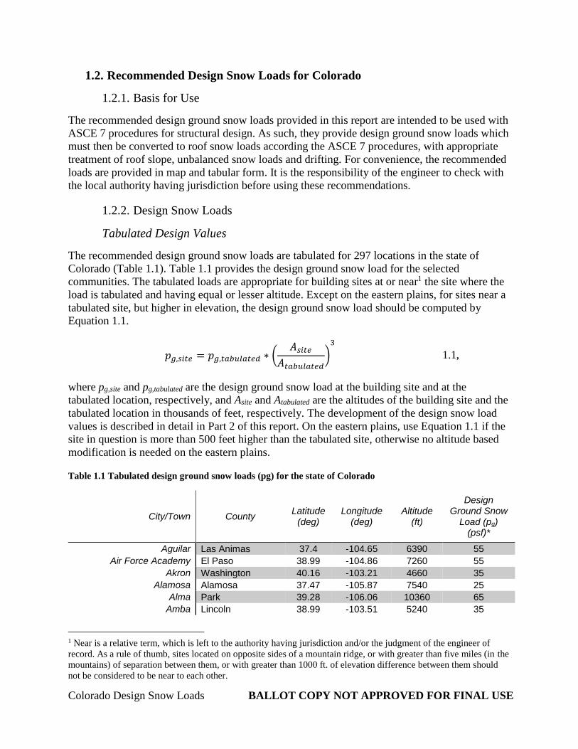
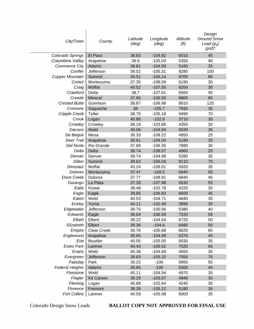
The recommended design ground snow loads are tabulated for 297 locations in the state of
Colorado (Table 1.1). Table 1.1 provides the design ground snow load for the selected
communities. The tabulated loads are appropriate for building sites at or near1 the site where the
load is tabulated and having equal or lesser altitude. Except on the eastern plains, for sites near a
tabulated site, but higher in elevation, the design ground snow load should be computed by
Equation 1.1.
𝑝𝑔,𝑠𝑖𝑡𝑒 = 𝑝𝑔,𝑡𝑎𝑏𝑢𝑙𝑎𝑡𝑒𝑑 ∗ (𝐴𝑠𝑖𝑡𝑒
𝐴𝑡𝑎𝑏𝑢𝑙𝑎𝑡𝑒𝑑)
3
1.1,
where pg,site and pg,tabulated are the design ground snow load at the building site and at the
tabulated location, respectively, and Asite and Atabulated are the altitudes of the building site and the
tabulated location in thousands of feet, respectively. The development of the design snow load
values is described in detail in Part 2 of this report. On the eastern plains, use Equation 1.1 if the
site in question is more than 500 feet higher than the tabulated site, otherwise no altitude based
modification is needed on the eastern plains.
Table 1.1 Tabulated design ground snow loads (pg) for the state of Colorado
City/Town County Latitude
(deg) Longitude
(deg) Altitude
(ft)
Design Ground Snow
Load (pg) (psf)*
Aguilar Las Animas 37.4 -104.65 6390 55
Air Force Academy El Paso 38.99 -104.86 7260 55
Akron Washington 40.16 -103.21 4660 35
Alamosa Alamosa 37.47 -105.87 7540 25
Alma Park 39.28 -106.06 10360 65
Amba Lincoln 38.99 -103.51 5240 35
1 Near is a relative term, which is left to the authority having jurisdiction and/or the judgment of the engineer of
record. As a rule of thumb, sites located on opposite sides of a mountain ridge, or with greater than five miles (in the
mountains) of separation between them, or with greater than 1000 ft. of elevation difference between them should
not be considered to be near to each other.
Colorado Design Snow Loads BALLOT COPY NOT APPROVED FOR FINAL USE 4
City/Town County Latitude
(deg) Longitude
(deg) Altitude
(ft)
Design Ground Snow
Load (pg) (psf)*
Colorado Springs El Paso 38.83 -104.82 6010 45
Columbine Valley Arapahoe 39.6 -105.03 5350 40
Commerce City Adams 39.81 -104.93 5160 35
Conifer Jefferson 39.52 -105.31 8280 100
Copper Mountain Summit 39.51 -106.14 9700 80
Cortez Montezuma 37.35 -108.59 6190 30
Craig Moffat 40.52 -107.55 6200 30
Crawford Delta 38.7 -107.61 6560 45
Creede Mineral 37.85 -106.93 8800 65
Crested Butte Gunnison 38.87 -106.98 8910 125
Crestone Saguache 38 -105.7 7930 35
Cripple Creek Teller 38.75 -105.18 9490 70
Crook Logan 40.86 -102.8 3710 30
Crowley Crowley 38.19 -103.86 4350 30
Dacono Weld 40.08 -104.94 5030 35
De Beque Mesa 39.33 -108.22 4950 25
Deer Trail Arapahoe 39.61 -104.04 5190 35
Del Norte Rio Grande 37.68 -106.35 7880 30
Delta Delta 38.74 -108.07 4960 25
Denver Denver 39.74 -104.98 5280 35
Dillon Summit 39.63 -106.04 9110 70
Dinosaur Moffat 40.24 -109.01 5920 35
Dolores Montezuma 37.47 -108.5 6940 55
Dove Creek Dolores 37.77 -108.91 6840 45
Durango La Plata 37.28 -107.88 6530 55
Eads Kiowa 38.48 -102.78 4220 30
Eagle Eagle 39.66 -106.83 6600 45
Eaton Weld 40.53 -104.71 4840 35
Eckley Yuma 40.11 -102.49 3890 30
Edgewater Jefferson 39.75 -105.06 5380 40
Edwards Eagle 39.64 -106.59 7220 55
Elbert Elbert 39.22 -104.54 6720 50
Elizabeth Elbert 39.36 -104.6 6480 50
Empire Clear Creek 39.76 -105.68 8620 65
Englewood Arapahoe 39.65 -104.99 5370 40
Erie Boulder 40.05 -105.05 5030 35
Estes Park Larimer 40.43 -105.52 7520 65
Evans Weld 40.38 -104.69 4650 30
Evergreen Jefferson 39.63 -105.32 7050 70
Fairplay Park 39.22 -106 9950 55
Federal Heights Adams 39.85 -105 5300 40
Firestone Weld 40.11 -104.94 4970 35
Flagler Kit Carson 39.29 -103.07 4940 30
Fleming Logan 40.68 -102.84 4240 30
Florence Fremont 38.39 -105.12 5180 35
Fort Collins Larimer 40.59 -105.08 5000 35
Colorado Design Snow Loads BALLOT COPY NOT APPROVED FOR FINAL USE 12
1.2.3. Additional Recommendations
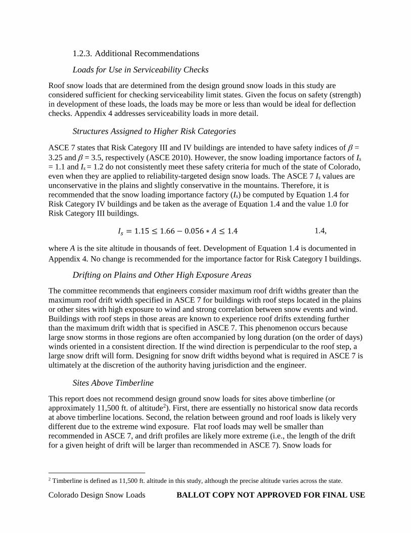
Loads for Use in Serviceability Checks
Roof snow loads that are determined from the design ground snow loads in this study are
considered sufficient for checking serviceability limit states. Given the focus on safety (strength)
in development of these loads, the loads may be more or less than would be ideal for deflection
checks. Appendix 4 addresses serviceability loads in more detail.
Structures Assigned to Higher Risk Categories
ASCE 7 states that Risk Category III and IV buildings are intended to have safety indices of =
3.25 and = 3.5, respectively (ASCE 2010). However, the snow loading importance factors of Is
= 1.1 and Is = 1.2 do not consistently meet these safety criteria for much of the state of Colorado,
even when they are applied to reliability-targeted design snow loads. The ASCE 7 Is values are
unconservative in the plains and slightly conservative in the mountains. Therefore, it is
recommended that the snow loading importance factory (Is) be computed by Equation 1.4 for
Risk Category IV buildings and be taken as the average of Equation 1.4 and the value 1.0 for
Risk Category III buildings.
𝐼𝑠 = 1.15 ≤ 1.66 − 0.056 ∗ 𝐴 ≤ 1.4 1.4,
where A is the site altitude in thousands of feet. Development of Equation 1.4 is documented in
Appendix 4. No change is recommended for the importance factor for Risk Category I buildings.
Drifting on Plains and Other High Exposure Areas
The committee recommends that engineers consider maximum roof drift widths greater than the
maximum roof drift width specified in ASCE 7 for buildings with roof steps located in the plains
or other sites with high exposure to wind and strong correlation between snow events and wind.
Buildings with roof steps in those areas are known to experience roof drifts extending further
than the maximum drift width that is specified in ASCE 7. This phenomenon occurs because
large snow storms in those regions are often accompanied by long duration (on the order of days)
winds oriented in a consistent direction. If the wind direction is perpendicular to the roof step, a
large snow drift will form. Designing for snow drift widths beyond what is required in ASCE 7 is
ultimately at the discretion of the authority having jurisdiction and the engineer.
Sites Above Timberline
This report does not recommend design ground snow loads for sites above timberline (or
approximately 11,500 ft. of altitude2). First, there are essentially no historical snow data records
at above timberline locations. Second, the relation between ground and roof loads is likely very
different due to the extreme wind exposure. Flat roof loads may well be smaller than
recommended in ASCE 7, and drift profiles are likely more extreme (i.e., the length of the drift
for a given height of drift will be larger than recommended in ASCE 7). Snow loads for
2 Timberline is defined as 11,500 ft. altitude in this study, although the precise altitude varies across the state.