Embed Size (px)
Citation preview

INSTALLATION
AND
OPERATION
INSTRUCTIONS
D-LuxDENTAL LIGHT
Model AL-701M
Model AL-702M
Model AL-705M
IMPORTANT
After installation is completed, check all
the bolts, screws and fasteners to confirm
that they are securely fastened.

– 2 –
TABLE OF CONTENTS
[1] SPECIFICATIONS ..................................................... 2
[2] WIRING DIAGRAM .................................................. 3
INSTALLATION INSTRUCTIONS
[3] UNIT MOUNT TYPE ................................................. 4
[4] CEILING MOUNT TYPE .......................................... 6
[5] TRACK MOUNT TYPE ............................................. 8
OPERATING INSTRUCTIONS
[6] OPERATION .............................................................. 9
[7] ADJUSTMENTS BALANCE ARM .......................... 10
[8] HALOGEN LAMP CHANGING ............................... 10
[9] CLEANING INFORMATION.................................... 11
[1] SPECIFICATIONS
1. Focal Distance...........................760 mm
2. Color Temperature....................4,200° Kelvin at 28,000 Lux
3. Light Intensity........................... High : 28,000 Lux
Low : 18,000 Lux
Composite Mode : 8,000 Lux
4. Light Pattern........................... ..220 x 85 mm at 760 mm
5. Power Requirement...................AC. 120 V 50/60 Hz
6. Bulb Type..................................Tungsten Halogen Type (JA 12-55WD/DL8)

– 3 –
[2] WIRING DIAGRAM
2-1.Unit Mount Type (AL-701M)
2-2.Ceiling Mount Type (AL-702M)
E
BlockTerminal
Transformer Box
1234L
N
E
120V Yellow115V Gray100V Black
0V(Common) White BlueBlownRed
Orange
0V
8.5V
10.6V
12.2V 1234
ON
OFF
ON
ON
ON
HeadYokeArm
Black
12
1
HighLow High/Low
OFF
Composite
White/Yellow
WhiteWhiteBlue
Blown
12
OrangeRedRed
OrangeSwitchPower
3A(T)Fuse
BrownBlue
Bulb
Transformer
Green/Yellow
Brown Brown
Blue
White/Yellow
OrangeRed
BlownBlue
2-3.Track Mount Type (AL-705M)
E
BlockTerminal
Transformer Box
1234L
N
E
120V Yellow115V Gray100V Black
0V(Common) White BlueBlownRed
Orange
0V
8.5V
10.6V
12.2V 1234
ON
OFF
ON
ON
ON
HeadYokeArm
Black
12
1
HighLow High/Low
OFF
Composite
White/Yellow
WhiteWhiteBlue
Blown
12
OrangeRedRed
OrangeSwitchPower
3A(T)Fuse
BrownBlue
Bulb
Transformer
Green/Yellow
Brown Brown
Blue
White/Yellow
OrangeRed
BlownBlue
1234
TrolleyTrack
OrangeRed
BlownBlue
E
BlockTerminal
Transformer Box
1234L
N
E
120V Yellow115V Gray100V Black0V(Common) White Blue
BlownRed
Orange
0V
8.5V
10.6V
12.2V 1234
ONOFF
ON
ON
ON
HeadYokeArm
Black
12
1
HighLow High/Low
OFF
Composite
White/Yellow
WhiteWhiteBlue
Blown
12
OrangeRedRed
OrangeSwitchPower
3A(T)×2Fuse
BrownBlue
Bulb
Transformer
Green/Yellow
Brown
Blue
Brown
Blue
White/Yellow
OrangeRed
BlownBlue

– 4 –
3-1. Dimensions Inches & (Millimeters)
[3] UNIT MOUNT TYPE (AL-701M)
3-2. Installation Instructions
3-2-1. Connect the light -head with the balance arm (This section also applies to [4] Ceiling mount type
and [5] Track type
All necessary parts are included in the carton box.
M3 x 6 Painted Screw........... 4pcs.
Yoke Cover............................ 1pce.
M5 x 10 Painted Screw......... 2pcs.
1) Install the light head to balance arm with M5 x 10
painted screws.
2) Connect the wire harness.
2P connector:orange/ brown to orange/brown
(same color to be met at each side of
connector.)
2P connector:brown/blue to white/white
(brown or blue can be met either line of
whites.)
1P connector : black to white (yellow-striped)
3) Attach the yoke cover with M3 x 6 painted screw.
160゚
160゚30゚
45゚
40゚
140゚
15゚
24''-57/64 (632)63/64 (25)
25''-5/8 (651)
17''-
35/6
4 (4
45.5
)

– 5 –
3-2-2. Insert the whole assembly consisting of light -head, balance arm, swing arm,
and transformer box into the pole.(See FIGUER 1.)
1) Attach pole (if not existing) to chair per manufacture’s instructions.
2) Slide pole adapter over cord, small end first.
3) Mount on pole guiding wire through (a pull cord may be helpful for this operation).
4) Attach a hospital grade plug cap(in Canada, CSA 5-15 Hospital Grade Plug Cap) to
wire end. This is to be installed by a licensed electrician only, in accordance with the
National Electrical Code(in the USA) or Canadian Electrical Code(in Canada), and
local electrical codes as applicable.
5) Remove arm locking key (save for possible future shipment).
6) Attach the rubber cover.
7) To convert to left-hand operation (See FIGURE 2.):
1. Remove small screw below H-bracket (as shown).
2. Rotate H-bracket to other position and reinsert screw (loosen large upper & lower
screws to help in moving bracket.
Robber Cap
Arm Locking Screw
H-Bracket
Right Hand Operation Slot
Left Hand Operation Slot
Right/Left Hand OperationScrew
Pole Adapter
Pole
Plug
FIGURE 1 FIGURE 2

– 6 –
[4] CEILING MOUNT TYPE (AL-702M)
4-1. Dimensions Inches & (Millimeters)
4-2. Installation Instructions
1) Secure mounting plate to the ceiling.
2) Route the power supply through the center of the mounting plate.
3) Install the levelling nuts between the mounting plate and the ceiling flange.
4) Install the ceiling flange to the mounting plate with washers and nuts supplied.
5) Insert the suspension into the ceiling flange and secure with roll pin and set screws supplied.
6) Be sure the suspension tube is plumb.
7) Slide the flange cover and flange cover ring (flat side up) over the suspension tube and secure
about half way up the tube. Use only one set screw as you will be moving this on final installation.
8) Install the light assembly to the suspension tube running the 3 wire cord up through the tube to
the ceiling flange. Secure with 4 Allen set screws.
9) Connect the incoming power to the 3 wire cord from the light assembly. Be sure to follow local
electrical codes.
10) Test light for proper operation.
11) Reposition flange cover and secure with flange cover ring - Secure all set screws.
(1) Power Supply Cable
(2) Mounting Plate
(3) Adjusting Nut
(4) Washer
(5) Nut
(6) Ceiling Flange
(7) Socket Screw for Flange
(8) Suspension Tube
(9) Roll Pin
(10) Socket Screw for Arm
(11) Flange Cover
(12) Cover Ring
(13) Socket Screw for Ring
(14) Suspension Tube of Arm
Location of Light Mount (Ceiling)in Reference to Chair Position
C
C
18"
12"
5
10
8
7
3
4
2
9
11
13
1
12
14
6
140゚
40゚
45゚
15゚
25''-5/8 (651)63/64 (25)
24''-57/64 (632)
21''-
5/32
(537
.5)
94''-
31/6
4 - M
ax.1
20''-
15/3
2(2
400-
Max
3060
) 21''-
5/16
(541
.5)


– 7 –
6"-1/16 (REF)
4"-9/32 (REF)
6"-15/32 (REF)
7/16"Mounting Holes

– 8 –
[5] TRACK LIGHT (AL-505T)
5-1. Dimensions Inches & (Millimeters)
5-2. Ceiling Preparation
For safety in operation as well as stability of the light source, the importance of proper ceiling structure
cannot be overemphasized. In general, a ceiling structure capable of supporting 200 lb. dead weight is
required.
1) In conventional ceilings with joists perpendicular to center line of light, attach pallet by at least
6 - 5/16 x 3" lag screws. Suitable holes are provided in pallet for most installations,utilizing
16" or 12" cc ceiling joists. For other spacings or locations, additional holes can be cut in pallet.
(SEE FIGURE 1.)
IMPORTANT:Locate transformer end of track at headrest end of chair. - Not legrest.
ElectricalFeed OpeningTransformer End
Used for 24" Centerto Center Joists
Used for 16" Centerto Center Joists
5/16 x 3 Lag Bolts (6)
FIGURE 1.
45゚
40゚
140゚
15゚
45''-
43/6
4 - 6
1''-2
7/64
(116
0-15
60)
55''-23/64 (1406)
14''-
31/3
2 - 3
0''-4
5/64
(380
- 78
0)
24''-11/16 (627)
21''-
5/32
(537
.5)
94''-
31/6
4 - M
ax. 1
10''-
15/6
4(2
400-
Max
2800
)
76''-31/32 (1955)
260°
– 9 –
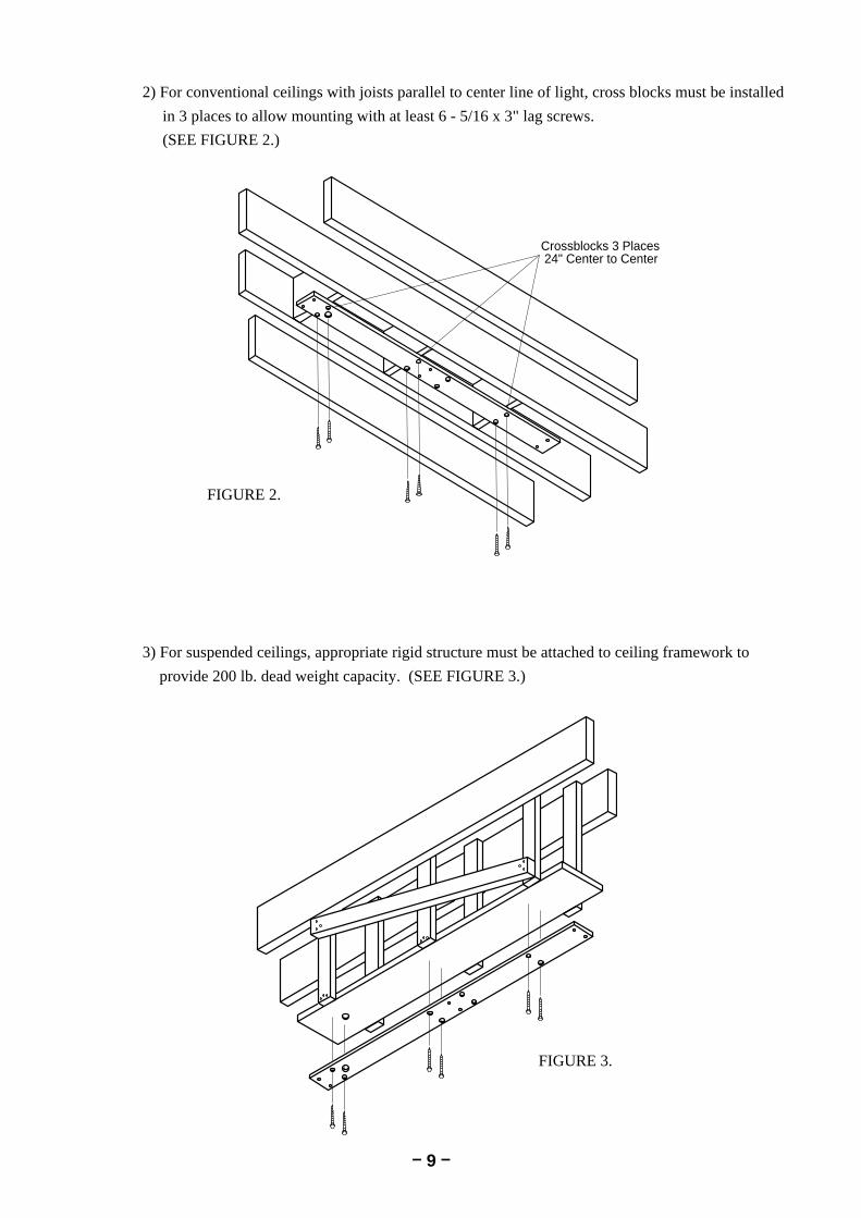
Crossblocks 3 Places 24" Center to Center
2) For conventional ceilings with joists parallel to center line of light, cross blocks must be installed
in 3 places to allow mounting with at least 6 - 5/16 x 3" lag screws.
(SEE FIGURE 2.)
3) For suspended ceilings, appropriate rigid structure must be attached to ceiling framework to
provide 200 lb. dead weight capacity. (SEE FIGURE 3.)
FIGURE 2.
FIGURE 3.

– 10 –
5-4. INSTALLATION INSTRUCTIONS
1) Lead out the power supply cable from the ceiling where the track light is mounted.
2) Run the power supply cable through the pallet and mount pallet.
3) Place track against pallet and slightly engage two mounting bolts at end opposite the electrical
opening.
4) Allowing the free end to hang down slightly for access, install the conduit box connector to the track.
5) Finish bolting track securely to pallet.
6) Connect wires from feed to terminal block.
7) Slide trolley onto track (end near electrical opening) with arrow on trolley oriented toward pulley on
track.
8) Carefully guide wire from trolley, around spring loaded pulley and back toward end of track.
9) Attach retainer clamp to small screw in track. Clip free end of trolley wire into plastic clip near end.
10) Install rubber bumpers at end of track in holes provided.
5-3. ELECTRICAL PREPARATION
Refer to FIGURE 4 for location of electrical feed opening in pallet, provide 3 wire, 115 V, 60Hz circuit
(15 amp. fuse or breaker through flexible conduit with enough slack to protrude at least 2" below pallet
when installed. Terminate conduit with 1/2" body box connector suitable for mounting through 3/16
thickness.
A readily accessible shut-off switch for this circuit is recommended. Use wiring suitable for 90˚C
service.
6"-5/16
4"-1/424" 8" 16"
65"-1/4
11/16"
3"-5/85"
1"-5/8 DIA (Electrical Feed Opening)
3/8" DIA HOLE1" DIA C'Bore (8Holes)Head of
Chair
Clamp (Factory Installed on Wire)
Install RubberBumpers after
Trolley
ConnectorGreen
BlackWhite
TransformerBox
ElectricalFeed
PlasticWire Clip Rubber Bumpers
Z Clip(Hold Bottom Cover)
To Trolley
Pulley Endcap

– 11 –
11) Check operation of trolley. It is factory
adjusted to provide smooth effortless travel,
without play; however rollers can be
readjusted if necessary. Loosen set screw
and adjust socket cap screw to very roller
clearance.
12) Unpack transformer / housing assembly and mount to track with screws provided.
13) Attach pigtail leads to corresponding power line wires at terminal block. Retain wires
under plastic clip.
14) Connect plug-in connector to trolley wire.
15) Carefully slide bottom cover onto track from free end. Be sure to engage lip onto Z bracket.
16) Install end-cap with screws provided.
17) Slide trolley back and forth checking for binding or rubbing.
18) Confirm that swing arm is properly adjusted to stay where it is placed. If necessary,
move head up or down to expose appropriate cross drilled nut and adjust with tool provided.
19) Turn on power and check electrical operation of light.
(1) Power supply cable
(2) Pallet
(3) Track
(4) End-cup
(5) Trolley
(6) Transformer Box
(7) Light Assembly
(8) Bottom Cover
(9) Rubber bumper
Trolley
AdjustmentScrew
Rollers
Set Screw
7
– 12 –
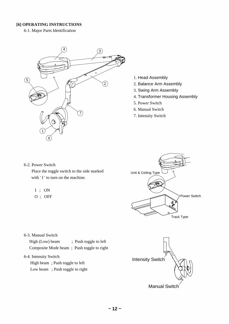
[6] OPERATING INSTRUCTIONS 6-1. Major Parts Identification
1. Head Assembly
2. Balance Arm Assembly
3. Swing Arm Assembly
4. Transformer Housing Assembly
5. Power Switch
6. Manual Switch
7. Intensity Switch
6-2. Power Switch
Place the toggle switch to the side marked
with ' I ' to turn on the machine.
I ; ON
O ; OFF
6-3. Manual Switch
High (Low) beam ; Push toggle to left
Composite Mode beam ; Push toggle to right
6-4. Intensity Switch
High beam ; Push toggle to left
Low beam ; Push toggle to right
Manual Switch
Intensity Switch
Power Switch
Unit & Ceiling Type
Track Type
1
2
34
6
7
5

– 13 –
[7] ADJUSTING TENSION of BALANCE ARM
7-1. Adjusting Tension of Balance Arm
Use slot A when making adjustment for drifting of balance arm.
Insert adjusting bar into slot A on top of balance arm, turn spring adjustment nut clockwise
for more tension ; counterclockwise for less tension.
7-2. Adjusting Angle of Head
Use slot D when adjusting head angle.
Remove three cover fixing screws and remove the balance arm cover.
Lift the balance arm to upmost position, and hold it.
Loosen screw B and C.
Insert adjusting bar into slot D on top of balance arm, turn spring adjustment nut clockwise
for downward angle ; counterclockwise for upward angle.
[8] HALOGEN LAMP CHANGING
Make sure the power supply is turned off.
Halogen bulb and surrounding parts be hot immediately after the lamp goes off.
Wait until they get cool down.
IMPORTANT
Do not touch glass with bare hand.
Halogen bulb surface must be clean.
Oil or body moisture will affect bulb span of life.
If glass surface is touched, clean with alcohol.
More Tension
Slot A
Head Balance Arm Cover
Balance Arm Cover
Adjusting Bar
Slot D
Upward
Downward
Less Tension
Cover Fixing Screw
Screw CScrew B
CAUTION

– 14 –
[9] CLEANING
1) To install replacement halogen bulb, turn light off and remove back cover by loosening
stopper screw.
2) Disconnect the electrical connector of halogen lamp.
3) Unlock the spring clip and pull the electrical wire of halogen bulb to remove the halogen
bulb from socket.
4) Attach the electrical wire of new halogen lamp and insert halogen lamp into socket.
5) After new halogen lamp is seated in housing, insert and lock spring clip into position.
6) Reattach back cover.
Use soft cloth or cotton only. Soak with alcohol. Clean both side of front shield.
Inside surface of reflector can be cleaned with a soft damp or dry cloth. Back side of the reflector
should be wiped gently with a soft cloth. Extreme care should be taken not to scratch surface or
mar appearance of painted surface.
Exterior cleaning is all that should be necessary until after many months of use.
1
2
4 6
5 4
3
1. Stopper Screw
2. Back Cover
3. Electrical wire of halogen bulb
4. Spring Clip
5. Halogen Bulb
6. Socket

– 15 –
TAKARA BELMONT CORPORATION1-1, 2-Chome, Higashi-shinsaibashi,Chuo-ku, Osaka, Japan
TEL. : (06) 6213-5945
FAX. : (06) 6212-3680
Printed in Japan 0407.MA
Book No. CAPN81B0