Embed Size (px)
Citation preview
76 'PHILIPS TECHNICAL REVIEW VOl. 1, No. 3
DEMONSTRATION MODEL ILLUSTRATING SUPERHETERODYNE RECEPTION
Introduction
At the World Exhibition held in Brussels lastyear, a demonstration model was exhibited whichillustrated in the most elementary manner themethod of operatien of modern radio receivers.It is of course generally known that in radiotransmission a carrier wave of high frequency isemployed and the much lower audio-frequenciesare transmitted as a modulation of the amplitude .of this carrier wave., The f"tinction of the recti-fying stage in the receiver is to separate theselow audio-frequencies from the high frequency ofthe carrier wave. Perhaps less well known is thesequence of operations which actually fake placein a superheterodyne receiver in which an "oscil-lator", a "converter valve" and an "intermediatefrequency" are U:sed.The main object ofthe demon-stration model described in the present article istherefore to 'illustrate the principles underlyingsuperheterodyne reception.
. The Superheterodyne Principle
In -superheterodyne receivers, not only is theincoming high-frequency carrier wav~ appropri-ately dealt with, but provision is also made for thesimultaneous generation of an additional oscillationby means of an oscillator, the frequency of thislocal oscillation differing by a specific number ofcycles pCI'second from the frequency of the carrierwave. The function of the converter valve is toreduce modulation to a 'new carrier wave of lowerfrequency. This is, do~e by producing a periodicfluctuation lp. the amplification of the incomingwave in synchronism with the self-generatedauxiliary oscillation of the oscillator. The alternating
. current la ~ the anode circuit of the converter.valve is giv"'enby-the product of the gradient 8 ofits characteristic' and the amplitude Vg of the alter-nating current component of the grid potential,thus: • ,; '. ' • '.
Ia " S Vg••• , ' (1), , .
The . gradi~nt 8 is" how varied.' with the angularfrequency ~O/,of the auxiliary oscillatioii, while thegrid potential Vg v~riestWl1:h the angular frequencyco, of the incoming carrier wave: Fgr' the:' sake Ofconvenience we' shall express the conditions ob-'taining simply. 'as ' sine' functi~ns: ..
8 = 80 + q cosw/,t
In the expression for the anode. current I" we thenhave, the term:
which can be resolved into two terms containingthe sum and the difference respectively of the 'frequency of the carrier wave and of the auxiliaryoscillation, thus:
Ia=....+a:~cos (Wh+W;) t+COS(W/,-W;) t~... (4)
The differential frequency (Wh - Wi), which isalso termed the intermediate frequency, is thenfiltered out in the receiver. The differentlal-frequencycircuits are very accurately tuU:edto an intermediatefrequency-band at .125 kilo-cycles, which from nowon acts in the receiver as the new carrier wave ofthe audio-frequency modulation. For if fJ in equation(3) is not constant, but varies with the audio-frequencies' to' be transmitted, then according toequation (4) the amplitude of la also will fluctuatewith the same frequency. After suitable amplifi-cation, the intermediate-frequency carrier waveis separated in the usual way in the rectifyingsection . of the receiver from the low-frequencymodulation, which it is required to render audiblein the loudspeaker.Thc chief advantage of superheterodyne reception
as compared with direct amplification and elimin-ation of the high-frequency carrier wave is thatthe tuning of the intermediate-frequency circuitsby the. reception of stations operating with verydifferent high-frequency carrier waves can alwaysbe very accurately maintained at the individualintermediate-frequency bands. Particularly thedesire to' make receiving apparatus capable ofreceiving, in addition to ordinary radio waves,also very short wave lengths, haS been responsible'for the adoption of the. superheterodyne principlein radio reception.
(2)(3)
The Octode
To generate the auxiliary oscillation and tomodulate it, on 'the incoming oscillation a specialconverter valve, the octode," is 'used' in Philipssuperheterodyne receivers. 'This, valve may beregarded as a triode and a pentode, connected inserlest-in which the,tl.'iode serves for the generation'of' the auxiliary ~scillation, while the pentodefurther handles the altemating current ge~eratedin the triode.
MAH.CH 1936 SUPERHETEH.ODYNE H.ECEPTION 77
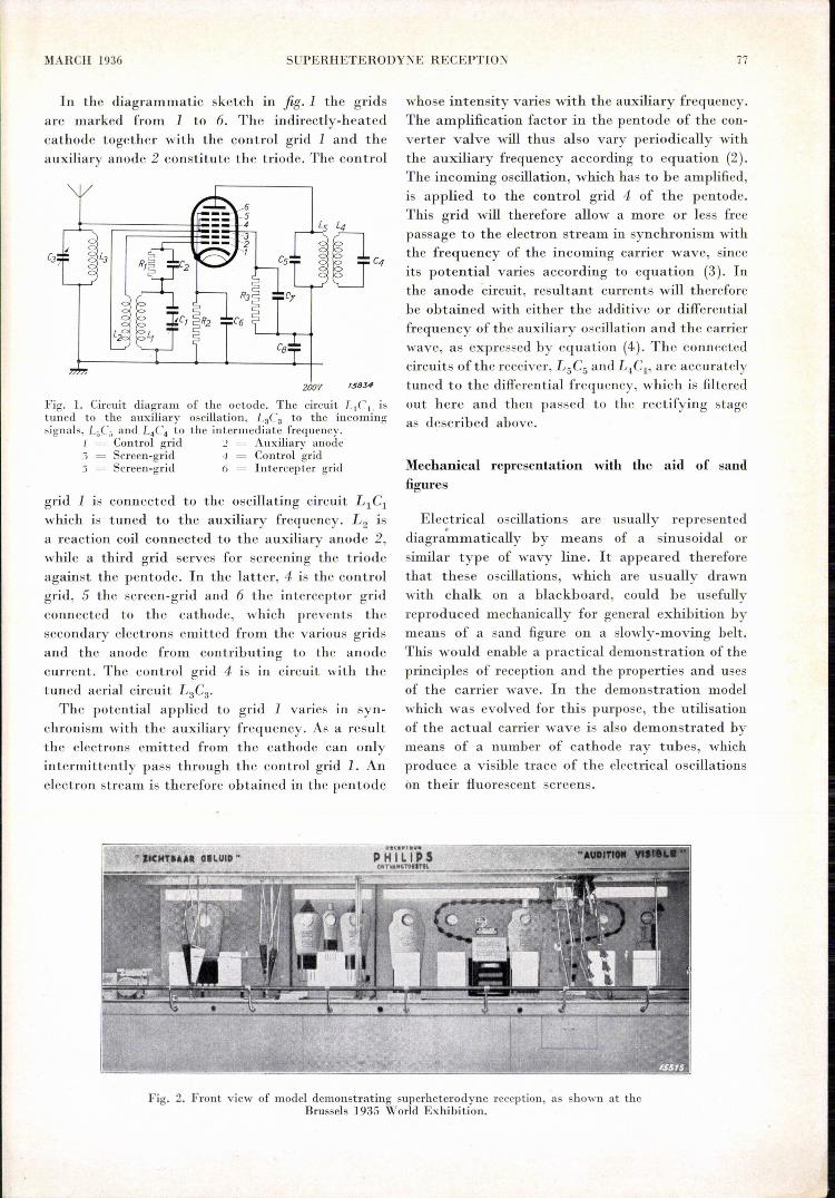
Fig. 2. Front view of model demonstru ting superheterodyne rcccption, as shown at theBrussels 1935 World Exhibi tion,
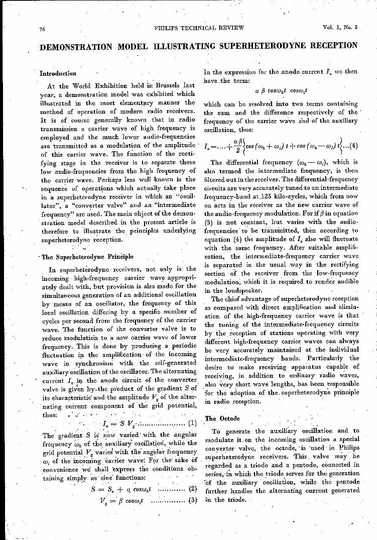
In the diagrammatic sketch in fig. 1 the gridsare marked from 1 to 6. The indirectly-heatedcathode together with the control grid 1 and theauxiliary anode 2 constitute the triode. The control
200V 15834
Fig. 1. Circuit diagram of the octode. The circuit L1C i. istuned to the auxiliary oscillation, t3C3 to the incomingsignals, L5C; and L,C4 to the intermediate frequency.
1 Control grid 2 Auxiliary anode3 Screen-grid 4 Control grid') = Screen-grid ó = Intercepter grid
grid 1 IS connected to the oscillating circuit Ll Clwhich IS tuned to the auxiliary frequency. L2 isa reaction coil connected to the auxiliary anode 2,while a third grid serves for screening the triodeagainst the pentode. In the latter, 4 is the controlgrid, 5 the screen-grid and 6 the interceptor gridconnected to the cathode, which prevents thesecondary electrons emitted from the various gridsand the anode from contributing to the anodecurrent. The control grid 4 is in circuit with thetuned aerial circuit L3C3•
The potential applied to grid 1 varies III syn-chronism with the auxiliary frequency. As a resultthe electrons emitted from the cathode can onlyintermittently pass through thc control grid 1. Anelectron stream is therefore obtained in the pentode
whose intensity varies with the auxiliary frequency.The amplification factor in the pentode of the con-verter valve will thus also vary periodically withthe auxiliary frequency according to equation (2).The incoming oscillation, which has to be amplified,is applied to the control grid 4 of the pentode.This grid will therefore allow a more or less freepassage to the electron stream in synchronism withthe frequency of the incoming carrier wave, sinceits potential varies according to equation (3). Inthe anode Circuit, resultant currents will thereforebe obtained with either the additive or differentialfrequency of the auxiliary oscillation and the carrierwave, as expressed by equation (4). The connectedcircuits ofthe receiver, L5C5 and L~C4' are accuratelytuned to the differential frequency, which is filteredout here and then passed to the rectifying stageas described above.
Mechanical representation with the aid of sandfigures
Electrical oscillations are usually representeddiagra~matically by means of a sinusoidal orsimilar type of wavy line. It appeared thereforethat these oscillations, which are usually drawnwith chalk on a blackboard, could be usefullyreproduced mechanically for general exhibition bymeans of a sand figure on a slowly-moving belt.This would enable a practical demonstration of theprinciples of reception and the properties and usesof the carrier wave. In the demonstration modelwhich was evolved for this purpose, the utilisationof the actual carrier wave is also demonstrated bymeans of a number of cathode ray tubes, whichproduce a visible trace of the electrical oscillationson their fluorescent screens.
78 PHILlPS TECHNICAL REVIEW Vol. 1, No. 3
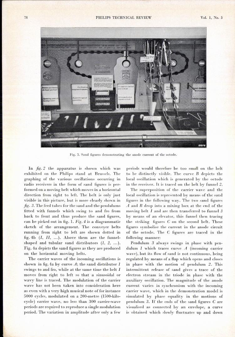
Fig. 3. Sand figures demonstrating the anode current of the octode.
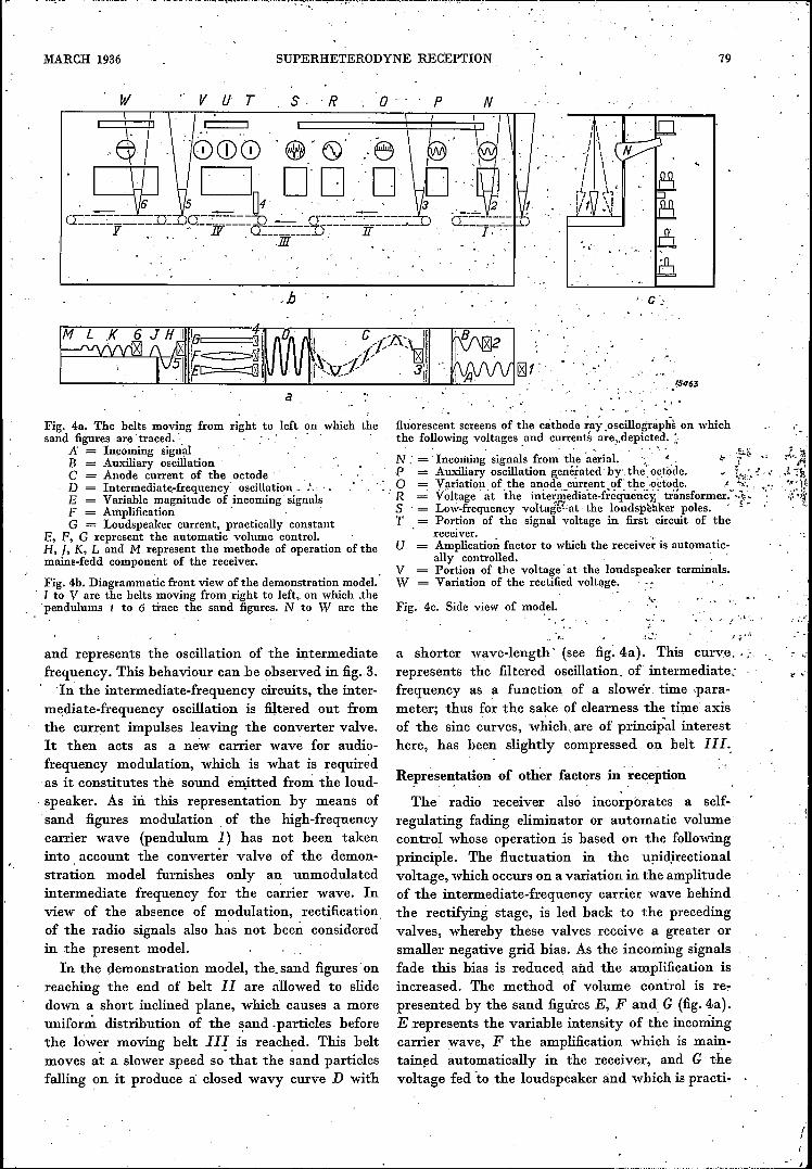
In fig. 2 the apparatus is shown which wasexhibited on the Philips stand at Brussels. Thegraphing of the various oscillations occurring inradio receivers in the form of sand figures is per-formed on a moving belt which moves in a horizontaldirection from right to left. The belt is only justvisible in this picture, but is more clearly shown infig. 3. The feed tubes for the sand and the pendulumsfitted with funnels which swing to and fro fromback to front and thus produce the sand figures,can be picked out in fig. 1. Fig. 4 is a diagrammaticsketch of the arrangement. The conveyer beltsrunning from right to left are shown dotted infig.4b (I, Il, ...). Above them are the funnel-shaped and tubular sand distributors (1, 2, ... ).Fig. 4a depicts the sand figures as they are producedon the horizontal moving belts.The carrier waves of the incoming oscillations is
shown in fig.4a by curve A; the sand distributor 1swings to and fro, while at the same time the belt Imoves from right to left so that a sinusoidal orwavy line is traced. The modulation of the carrierwave has not been taken into consideration hereas even with a very high musical note of for instance5000 cycles, modulated on a 200-metre (1500-kilo-cycle) carrier wave, no less than 300 carrier-waveperiods are required to reproduce a single modulationperiod. The variation in amplitude after only a few
periods would therefore be too small on the beltto be distinctly visible. The curve B depicts thelocal oscillation which is generated by the octodein the receiver. It is traced on the belt by funnel 2.
The superposition of the carrier wave and thelocal oscillation is represented by means of the sandfigures in the following way. The two sand figuresA and B drop into a mixing box at the end of themoving belt I and are then transferred to funnel 3by means of an elevator, this funnel then tracingthe striking figures C on the second belt. Thesefigures symbolise the current in the anode circuitof the octode. The C figures are traced in thefollowing manner:
Pendulum 3 always swings in phase with pen-dulum 1 which traces curve A (incoming carrierwave), but its flow of sand is not continuous, beingregulated by means of a flap which opens and closesin phase with the motion of pendulum 2. Thisintermittent release of sand gives a trace of theelectron stream in the triode in phase with theauxiliary oscillation. The magnitude of the anodecurrent varies in synchronism with the incomingcarrier wave, which in the demonstration model issimulated by phase equality in the motions ofpendulum 3. If the ends of the sand figures Carevisualised as connected by an envelope, a curveis obtained which slowly fluctuates up and down
MARCH 1936 SUPERHETERODYNE RECEPTION 79
w v ij T S, 'R o p N
,h
Fig. 4a. The belts moving from right to left on which thesand figures are' traced. '. '.
A' = Incoming signalB = Auxiliary' oscillationC = Anode current of the octodeD = Intermediatè-frequency' oscillation .. _.E = Variable magnitude of incoming' signalsF = AIllplification' .G = Loudspeaker current, practically constant
E, F, G represent the automatic volume control.H, 1, K, L and M represent the methode of operation of themains-fedd component of the receiver.
Fig. 4b. Diagrammatic front view of the demonstration model.1 to V are the belts moving from right to left, on which .thependulums 1 to 6 trace the sand figures. N to Ware the
and represents the oscillation of the intermediatefrequency. This behaviour can be observed in fig. 3.
In the intermediate-frequency circuits, the inter-mediate-frequency oscillation is filtered out fromthe current impulses leaving the converter valve.It then acts as a new carrier wave for audio-frequency modulation, which is what is requiredas it constitutes the sound emitted from the loud-,speaker. As in this representation by means' ofsand figures modulation of the high-frequencycarrier, wave (pendulum 1) has not been takeninto account the converter valve of the demon-stration model furnishes only an unmodulatedintermediate frequency for the ca~rier wave. Inview of the absence of modulation, rectificationof the radio signals also has not been consideredin the present model.
In the demonstratien model, the. sand figures' onreaching the end of belt 11 are allowed to slidedown a short inclined plane, which causes a moreunifor~ distribution of the .sand .particles beforethe low~r moving belt LlI. is reached. This beltmoves at a slower speed so that the sand particlesfalling on it produce a: closed wavy curve D with
"
, .15463·-,l·
fluorescent screens of the cathode ~ay.oscillogràphs on whichthe following voltages .and currents are"depicted.:
N: = Incoming signals from the 'aerial. .. ',~(' ,:P = Auxiliary oscillation g_enératedby the ootode. - i:~,,'o Variation of the anode current of the octode. " "'_'. '.
• R = Voltage at the iniermediate-f~equênëy,' tránsformer:',;~"S = Low-frequency voltagbl'at, the loudspeaker poles. ,i -T = Portion of the signal voltage in first circuit of the
. receiver. 'U = Amplication factor to which the receiver is automatic-
ally controlled. ,V = Portion of the voltage at the loudspeaker terminals.W = Variation of the rectified voltage.
,-
Fig. 4e. Side view of model.., ..'
.1,_'· I ~...,.'a shorter wave-length' (see fig: 4a). This curve, ,:represents the filtered oscillation, of intermediate,;frequency as a function of a slower time ,para-meter; thus for the sake of clearness the time axisof the sine curves, which, are of principal interesthere, has been slightly compressed 0]1 belt LlL:
Representation of other factors in' reception
The' radio receiver alsó incorporates a self-regulating fading eliminator or automatic volume'control whose operatien is based on the followingprinciple. The fluctuation in the unidirectionalvoltage, which occurs on a variation in the amplitudeof the intermediate-frequency carrier wave behindthe rectifying stage, is led back to the precedingvalves, whereby these valves receive a greater orsmaller negative grid bias. As the incoming signalsfade this bias is reduced, and the amplification isincreased. The method of volume control is re-presented by the sand figures E, F and, G (fig.4a).E .represents the variable intensity of the incomingcarrier wave, F the amplification which is main-tained automatically in the receiver, and. G thevoltage fed 'to the loudspeaker and which is practi-
1,
80 PHILIPS TECHNICAL REVIEW Vol. 1, No. 3
•• ZICHTBAAR GELUID"
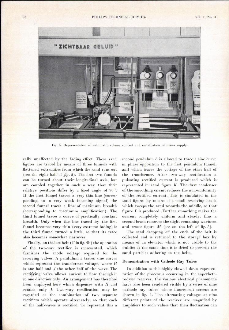
second pendulum 6 is allowed to trace a sine curvein phase opposition to the first pendulum funnel,and which traces the voltage of the other half ofthe t.ransformer. After two-way rectification apulsating rectified current is produced which isrepreserrted in sand figure K. The first condenserof the smoothing circuit reduces the non-uniformityof the rectified current. This is simulated in thesand figures by means of a small revolving brushwhich sweeps the sand towards the middle, so thatfigure L is produced. Further smoothing makes thecurrent completely uniform and steady; thus asecond brush removes the slight remaining wavinessand traces figure M (see on the left of fig. 5).
The sand dropping off the ends of the helt iscollected and is returned to the storage box hymeans of an elevator which is not visible to thcpuhlic; at the same time it is dried to prevent thcsand particles adhering to the helts.
Fig. 5. Representation of automatic volume control and rectification of mains supply.
cally unaffected by the fading effect. These sandfigures are traced by means of three funnels withflattened extremities from which the sand runs out(see the right half of fig. 5). The first two funnelscan be turned about their longitudinal axis, butare coupled together in such a way that theirrelative positions differ hy a fixed angle of 900
•
If the first funnel traces a very thin line (corres-ponding to a very weak incoming signal) thesecond funnel traces a line of maximum breadth(corresponding to maximum amplification). Thethird funnel traces a curve of practically constantbreadth, Only when the line traced hy the firstfunnel hecomes very thin (very extreme fading) isthe third funnel turned a little, so that its tracealso hecomes somewhat narrower.Finally, on the last helt (V in fig.4b) the operatien
of the two-way rectifier is represented, whichfurnishes the anode voltage required for thereceiving valves. A pendulum 5 traces sine curveswhich represent the transformer voltage, where His one half and ] the other half of the wave. Therecti£ying valve allows current to flow through itin one direction only. An arrangement has thereforebeen employed here which dispenses with Handretains only]. Two-way rectification may beregarded as the comhination of two separaterectifiers which operate alternately, so that eachof the half-waves is rectified. To represent this a
Demonstration with Cathode Ray Tubes
In addition to this highly slowed down represen-tation of the processus occurring in the superhete-rodyne receiver, the various electrical phenomenahave also been rendered visihle by a series of ninecathode ray tuhes whose fluorescent screens areshown in fig. 2. The alternating voltages at ninedifferent points of the receiver are magnified byamplifiers to such values that their fluctuation can
MAneH 1936 SUPERHETERODYNE RECEPTION ill
be demonstrated with the aid of the cathode raytubes. Each amplifier has its own rectifier so thatno disturbing coupling actions can be produced.
The amplified voltages are applied to thedeflection plates of the cathode ray oscillographswhich deflect the electron beam in a verticaldirection. By means of a horizontal time-basedeflection 1) of suitable frequency the alternatingcurrent figures are traced on the fluorescent screens.The period of the time-base can be adjusted asrequired, but it must be a whole multiple of thealternating voltage represented.In fig. 4b the screens of the tubes are indicated
by the letters N to W. The suffixes indicate thenature of the trace on each screen. By applyingmore or less quickly varying saw-tooth voltages,sinusoidal figures were obtained on the screenwhich showed more or fewer oscillations as indicatedin fig.4.
In place of the saw-tooth voltage variation ofthe time-base a sinusoidal voltage ofmains frequencycan also be applied to the horizontal deflectingsystem or to both systems. In the first case theso-called Lissajous curves are obtained and in thesecond case ellipses, which may be seen on thescreens in figs. 2 and 3.
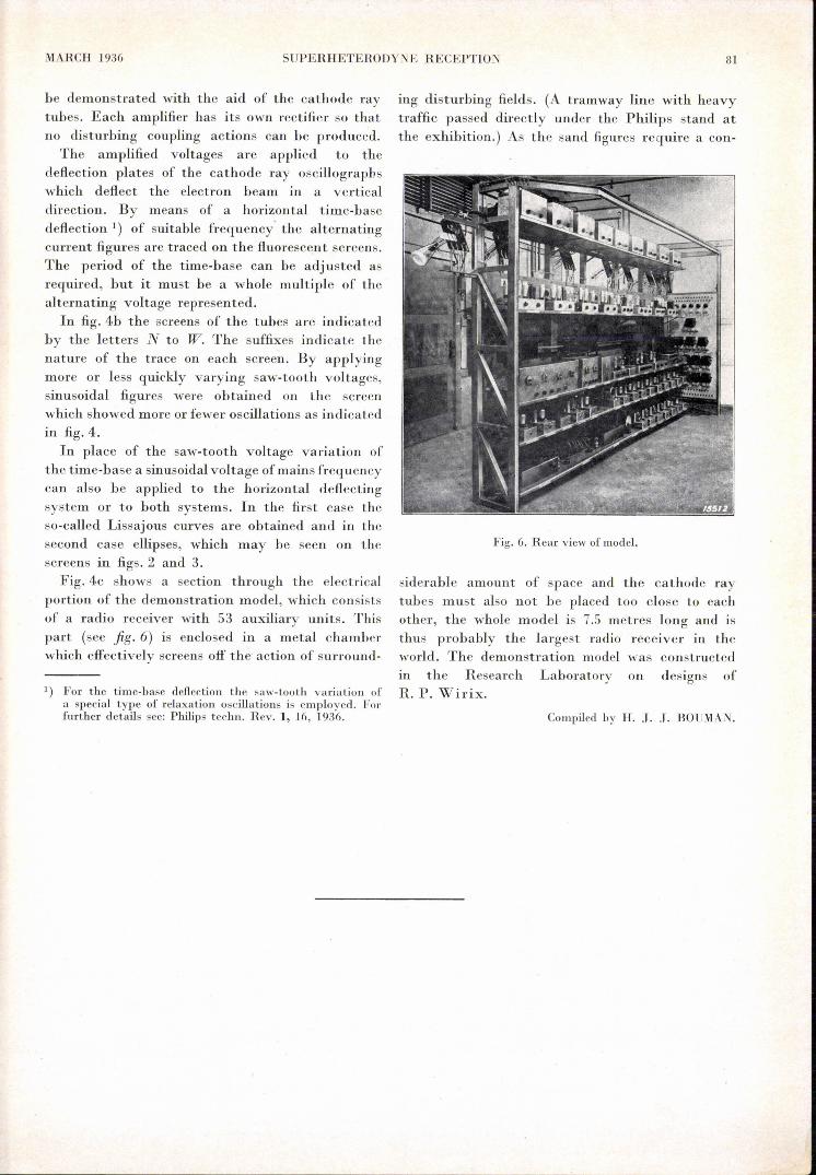
Fig. 4c shows a section through the electricalportion of the demonstration model, which consistsof a radio receiver with 53 auxiliary units. Thispart (see fig. 6) is enclosed in a metal chamberwhich effectively screens off the action of surround-
") For the time-base deflection the saw-tooth variation ofa special type of relaxation oscillations is employed. Forfurther details see: Philips techno Rev. 1, 16, 1936.
ing disturbing fields. (A tramway line with heavytraffic passed directly under the Philips stand atthe exhibition.) As the sand figures require a con-
Fig. 6. Rear view of model.
siderable amount of space and the cathode raytubes must also not be placed too close to eachother, the whole model is 7.5 metres long and isthus probably the largest radio receiver in theworld. The demonstration model was constructedIII the Research Laboratory on designs ofR. P. Wirix.
Cornpiled by H. J. J. BO UMAN.


![INDEX [] Wireless/30s... · GENERAL INDEX PAGE ... Radiotecnica, E. Montù Superheterodyne Receiver, Alfred T. Wells Television Reception, Manfred von Ardenne](https://img.pdfslide.us/doc/110x75/5b15eff07f8b9a472e8c0603/index-wireless30s-general-index-page-radiotecnica-e-montu-superheterodyne.jpg)