Embed Size (px)
Citation preview

DELTABEAMComposite Beam
Technical Manual
Version: Peikko Group 8/2014

DELTABEAMComposite Beam
System benefits
DELTABEAM is a superior composite beam enabling slim-floors for multi-storey buildings of any type, whether low-rise or high-rise. Its composite action between steel and concrete allows for creative structures with large open spaces. Multiple fire tests have proven DELTABEAM to have excellent fire resistance without any additional protection. Its shallow design decreases the building’s floor-to-floor height, while eliminating conflicts with HVAC systems.
Since 1989 DELTABEAMs have been used in thousands of buildings globally. DELTABEAMs have been subjected to a rigorous testing program and the solution is widely approved in various countries. Peikko’s technical support is always available to help you to find the most suitable solution for your project.
• Quick and easy installation• Standardized connections• Saves construction height• Easy HVAC installation• Cost-efficient• Flexible DELTABEAM types and details• Flexible lay-outs through the whole life cycle• Fire rating as high as R180 without additional protection• CE marked• Enables to get LEED and BREEAM certification points• Local technical support
www.peikko.com

1. Product properties ....................................4
1.1 Structural behavior . . . . . . . . . . . . . . . . . . . . . . . . . . . 7
1.1.1 Temporary conditions 7
1.1.2 Final conditions 9
1.1.3 In accidental situation 10
1.2 Application conditions . . . . . . . . . . . . . . . . . . . . . . . 11
1.2.1 Loading and environmental conditions 11
1.2.2 Positioning of DELTABEAM 11
1.2.3 Interaction with floor units 12
1.2.4 Expansion and construction joints of the slabs 13
1.2.5 Holes and additional connections 15
1.3 Other properties . . . . . . . . . . . . . . . . . . . . . . . . . . . . . 15
2. Resistances ............................................17
About DELTABEAM 4
18Selecting DELTABEAM
23Installation of DELTABEAM
Contents
Revision: 001
20
22
Annex A – Intial information
Annex B – The possibilities DELTABEAM offers

1. Product properties
DELTABEAM is a slim-floor composite beam which is integrated into the floor. The beam is completely filled with concrete on-site. The infill concrete and DELTABEAM form a composite structure after the concrete has hardened. DELTABEAM acts as a steel beam before the infill concrete has reached the required strength. DELTABEAM is made of cut steel plates and welded together at the factory (see figure 1). It can be used with all common floor types. See the ideal floor types in figure 2.
Figure 1. DELTABEAM parts.
Figure 2. Ideal floor types with DELTABEAM.
air hole
casting holetop plate
fire rebars
bottom platebeam ledge
webweb hole
Hollow-core slabs Filigran type floors
Steel decking
DELTABEAM Composite Beam4
About DELTABEAM

There are two types of DELTABEAM. The D-type DELTABEAM has ledges on both side of the beam. This beam type is able to carry floor units on both sides of the beam. The DR-type DELTABEAM has a vertical web and ledge only on one side. Both types of DELTABEAM can be used as edge beams to carry floor units at only one side of the beam. Curved floor edges can be made by combining D-type beams with curved formwork. Table 1 shows the use of DELTABEAM types.
Table 1. The use of DELTABEAM types.
D-type DELTABEAM DR-type DELTABEAM
Used as an intermediate beam Used as an edge beam when a narrower beam is needed
The vertical web is protected against fire with other structure or with separate fire protection
Used as an edge beam with formwork sheet Used on floor openings or floor edges
The free side of DELTABEAM is protected against fire with concrete
Fire protection on the vertical web
5Version: Peikko Group 8/2014
About DELTABEAM

DELTABEAMs can be used as single-span beams or in multi-span beam construction. DELTABEAMs can also be used for cantilever beam construction. In multispan beam construction, Gerber connections provide continuity to lines of DELTABEAMs (see figure 3). Peikko designs the locations of the Gerber connections. Shim plates are used by default to allow for installation tolerance.
Figure 3. Gerber connections enable the continuity of the DELTABEAM line.
Shim plate
Gerberconnection
Gerberconnection
Gerberconnection
Gerberconnection
DELTABEAMs can be used with all common column types. DELTABEAMs are connected to the columns with corbels or fixed to the top of the column with bolts or welds. Peikko’s PCs Corbel is recommended for connecting DELTABEAMs to concrete columns (see figure 4). PCs Corbel is a modular hidden column corbel designed especially for DELTABEAM. See PCs Corbel’s technical manual for more information. Figure 4. DELTABEAM connected to a precast concrete column using Peikko’s PCs Corbel.
DELTABEAM Composite Beam6
About DELTABEAM

1.1 Structural behavior
1.1.1 Temporary conditions
DELTABEAM acts as a steel beam before the infill concrete has reached the required strength. During the erection stage, all loads are transferred to DELTABEAM through the beam ledges (see figure 5). It is important to position the hollow-core slab end correctly onto the beam ledge because this affects the DELTABEAM’s design (see section 1.2.2). The erection stage design is carried out in accordance with elastic design principles, with the loads acting in the erection stage. The precamber of DELTABEAM compensates for the deflection in the erection stage. The amount of precamber depends on the length of DELTABEAM, on the loads in the erection stage and on the selected static system.
Figure 5. Load transfer in temporary condition.
The effects of loads such as torsion during the erection stage must be taken into account when designing the connection details and the supporting structures. For example, variable beam spacing, variable load values or asymmetrically assembled floors can cause torsion.
Propping is used with hollow-core slabs only to prevent DELTABEAM from rotating at the supports. The function of beam propping is not to prevent deflection. No propping is required provided that the DELTABEAM’s connec-tions and supporting structures are designed for the loads during the erection stage. Temporary props should be designed for temporary erection loads acting to them. DELTABEAM is capable of transferring the effects of an eccentric load back to the column. More information about propping can be found from section Installation of DELTABEAM. Peikko’s technical support is always available to help with any installation and propping issues.
DELTABEAM props are located as close to the DELTABEAM support as possible (see figure 6). Props are placed below the web, on the loaded side. Props should not be removed until the slab cast and the infill concrete of DELTABEAM have reached the required strength.
Figure 6. Propping DELTABEAM.
7Version: Peikko Group 8/2014
About DELTABEAM

In case of filigran or other solid slab types that are propped during construction phase, propping may be necessary along DELTABEAM to ensure that the beam and the slab do not separate while concrete grouting is done depending on the type of formwork.
Propping is always required when DELTABEAM is bearing on the end of a narrow wall running parallel with the beam and proper torsionally rigid connection with two bolts is not possible to be used (see figure 7).
Figure 7. Propping when DELTABEAM is bearing on the end of a wall.
When the purpose of DELTABEAM is to transfer floor loads to a wall-type beam above, DELTABEAM must be correctly propped. DELTABEAM must be propped according to the project’s erection method statement before the floor units are assembled. Props must not be removed until the upper wall is capable of bearing the full floor load. Figure 8 shows detail of DELTABEAM with a wall-type beam above.
Figure 8. The purpose of the vertical reinforcement is to tie DELTABEAM and the wall-type beam together.
NOTE: DELTABEAM PROPPING IS USED WITH HOLLOW-CORE FLOORS ONLY TO PREVENT THE BEAM FROM ROTATING AT ITS SUPPORTS.
DELTABEAM Composite Beam8
About DELTABEAM

1.1.2 Final conditions
The infill concrete and DELTABEAM form a composite structure after the concrete has reached the required strength. In final condition, the loads are transferred to DELTABEAM through a compression arc against an inclined web (see figure 9). The load transfer is proven by load tests, where DELTABEAM was tested without the beam ledges. Transverse reinforcement, which is assembled through the DELTABEAM’s web holes, secures load transfer.
Figure 9. Load transfer in final condition.
The shear connection between the infill concrete and DELTABEAM is formed by the dowel action of the web holes. Static loading tests have proven that the composite interaction is full.
The structural engineer designs the connections between DELTABEAM and the supporting structure. The connec-tion must be designed such that the DELTABEAM’s support reactions are transferred to the supporting structure (e.g., a column, wall or other beam). This supporting structure must be designed to bear the reactions from DELTA-BEAM. Peikko designs DELTABEAMs according to the connection details. Peikko also designs the internal beam-to-beam connections, such as Gerber and Side connections. Indicative connection details can be downloaded from the software download center on Peikko’s website www.peikko.com. The appearance of the connection can be finished by cutting the DELTABEAM’s bottom plate according to the connection detail (see figure 10). If necessary, the bottom plate edge can be beveled or arched in plane of the bottom plate.
Figure 10. The DELTABEAM’s bottom plate is arched because of the tube column.
9Version: Peikko Group 8/2014
About DELTABEAM

1.1.3 In accidental situation
Buildings should be designed to carry an extent of localized failure from an unspecified cause without dispropor-tionate collapse. The transverse and parallel reinforcement should be therefore designed for a design tensile load defined according to EN 1991-1-7 and its National Annex in the accidental situation.
Fire situation
The evaluation of the fire resistance of DELTABEAM is based on standard fire tests and design guidelines obtained from tests. DELTABEAM can have fire rating as high as R180 depending on local approvals. Check the availability from Peikko’s local technical support. DELTABEAM is dimensioned in compliance with the fire rating requirements of the project.
When needed, the designed number of fire rebars is installed inside DELTABEAM at the factory (see figure 11). High fire resistance is achieved by fire rebars and infill concrete. The DELTABEAM’s fire rebars and the webs act as tensile reinforcement in the event of fire. The rebars compensate for the strength that the bottom plate loses, meaning that additional fire protection is not normally needed.
Figure 11. Fire rebars inside DELTABEAM.
The vertical web of the DR-type DELTABEAM must be protected against fire by other structures or by protective materials/finishes. Separate fire protection is needed when there is no other structure protecting the vertical web. Peikko will determine the DR-type DELTABEAM’s need for separate fire protection on a case-by-case basis. The material and thickness of the separate fire protection are determined on a case-by-case basis by the fire engineer.
DELTABEAM Composite Beam10
About DELTABEAM
1.2 Application conditions
1.2.1 Loading and environmental conditions
DELTABEAMs are designed by considering the entire loading history. Each DELTABEAM is designed separately on the basis of initial information of the project. The initial information is needed for manufacturing and designing DELTABEAMs. The contents of the initial information are presented in figure 22. Appendix A contains the list of required DELTABEAM details and an example of a DELTABEAM data sheet. Every DELTABEAM has a unique identifi-cation code in the project.
The dynamic design in serviceability limit state is taken into account when designing DELTABEAMs, if requested by the structural engineer. The structural engineer analyzes vibrations for the entire project. Peikko’s technical support is always available to help with vibration issues.
It is assumed that walls located on DELTABEAMs have no effect on the beams unless loading information is pro-vided concerning the walls located on DELTABEAMs. It is also assumed as a default in the DELTABEAM design that the topping concrete of the flooring is cast in a separate phase after the infill concrete of DELTABEAM has reached the required strength. If the topping concrete is to be cast simultaneously with the infill concrete, Peikko should be informed. The order of concrete casting significantly affects the DELTABEAM’s design. The infill concrete grade in the DELTABEAM design is C25/30, unless otherwise stated. The minimum infill concrete grade is C20/25 normal weight structural concrete. DELTABEAM should always be cast in full in one run.
The HVAC system can be installed below the floor or, in some cases, inside the floor. If the DELTABEAM’s web holes are used for HVAC installation, the impact must be taken into account when DELTABEAM is designed. Therefore, Peikko must be informed if the DELTABEAM’s web holes are to be used for HVAC installation in order to find the optimal location for the piping.
DELTABEAMs are either primed or hot-dip galvanized. These surface coating techniques also ensure durability during delivery and installation. The DELTABEAM’s visible bottom part is primed to minimum 40 μm. Other surface treatments may be delivered upon agreement with the customer. The customer does the final painting on-site.
The free water in the DELTABEAM’s fresh infill concrete reacts with cement in the normal hardening process, as in other concrete structures. The concrete requires a certain drying time and humidity level before the surface materials of the floor can be installed. It is recommended that water-reducing agents be used rather than high water-cement ratio to make the structural concrete mix for DELTABEAM casting. By being able to decrease the required amount of water, the concrete’s drying time is reduced. To control the concrete’s drying time on-site, normal guidelines for the prevailing environmental conditions should be followed.
1.2.2 Positioning of DELTABEAM
The bearing length of the hollow-core slabs or other deck may vary from their standard product requirement. For the standard requirement in the DELTABEAM’s design, see figure 12. Using a smaller bearing length affects the design and the dimensioning of DELTABEAM. If requested by the supplier of the hollow-core slabs DELTABEAM with wider ledges can be delivered.
Figure 12. The minimum bearing lengths of standard DELTABEAM profiles with hollow-core slabs.
max. 2077.5 mm, D-type DELTABEAM when b ≤ 300 mm80 mm, DR-type DELTABEAM when h ≤ 320 mm110 mm, with other DELTABEAMs{min.
11Version: Peikko Group 8/2014
About DELTABEAM
1.2.3 Interaction with floor units
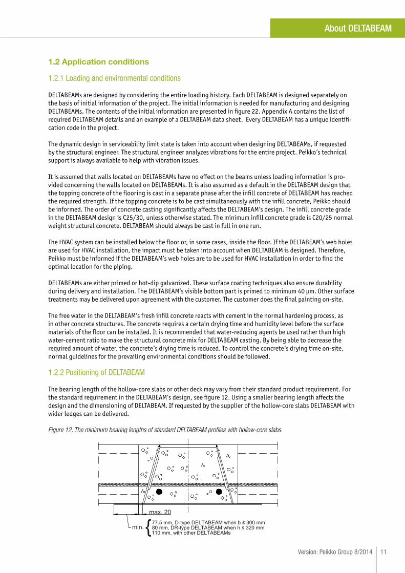
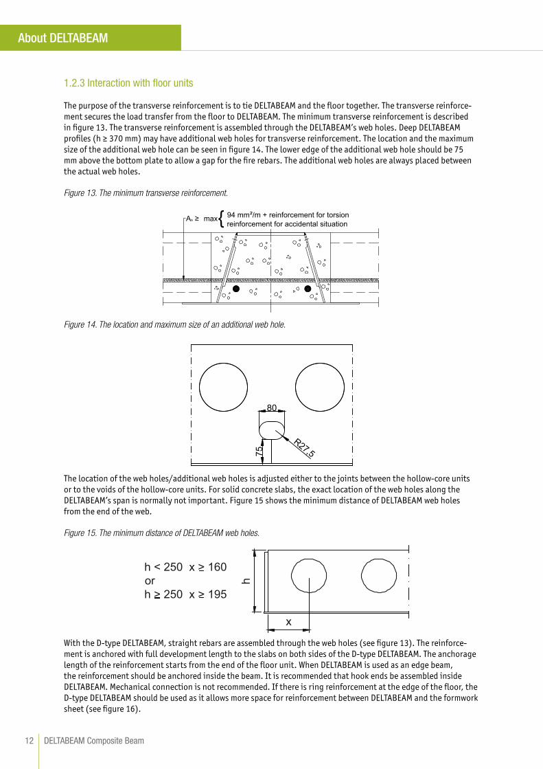
The purpose of the transverse reinforcement is to tie DELTABEAM and the floor together. The transverse reinforce-ment secures the load transfer from the floor to DELTABEAM. The minimum transverse reinforcement is described in figure 13. The transverse reinforcement is assembled through the DELTABEAM’s web holes. Deep DELTABEAM profiles (h ≥ 370 mm) may have additional web holes for transverse reinforcement. The location and the maximum size of the additional web hole can be seen in figure 14. The lower edge of the additional web hole should be 75 mm above the bottom plate to allow a gap for the fire rebars. The additional web holes are always placed between the actual web holes.
Figure 13. The minimum transverse reinforcement.
As ≥ max 94 mm² + reinforcement for torsionreinforcement for accidental situation{
Figure 14. The location and maximum size of an additional web hole.
75
80
R27,5
The location of the web holes/additional web holes is adjusted either to the joints between the hollow-core units or to the voids of the hollow-core units. For solid concrete slabs, the exact location of the web holes along the DELTABEAM’s span is normally not important. Figure 15 shows the minimum distance of DELTABEAM web holes from the end of the web.
Figure 15. The minimum distance of DELTABEAM web holes.
h < 250 x > 160orh > 250 x > 195
h
x
With the D-type DELTABEAM, straight rebars are assembled through the web holes (see figure 13). The reinforce-ment is anchored with full development length to the slabs on both sides of the D-type DELTABEAM. The anchorage length of the reinforcement starts from the end of the floor unit. When DELTABEAM is used as an edge beam, the reinforcement should be anchored inside the beam. It is recommended that hook ends be assembled inside DELTABEAM. Mechanical connection is not recommended. If there is ring reinforcement at the edge of the floor, the D-type DELTABEAM should be used as it allows more space for reinforcement between DELTABEAM and the formwork sheet (see figure 16).
DELTABEAM Composite Beam12
About DELTABEAM

Figure 16. D-type DELTABEAM used as an edge beam with transverse and ring reinforcement.
Tensile or compression forces acting parallel to beam axis are usually transferred by ring reinforcement located in the area between the hollow-core slab end and the inclined web of DELTABEAM. Peikko must be informed if it is required to transfer normal forces through DELTABEAM profile.
Reinforcement against torsion is designed with edge beams or, when the spans or the loads differ significantly, at the opposite sides of the beam. The magnitude of the torsion varies depending on whether propping is used during the erection stage. Figure 17 shows the design principal for torsion. With hollow-core slabs, dimension hc is the minimum thickness of the top hull. In the case of structural topping on the hollow-core slabs, the topping may be taken into account in hc, according to the judgment of the structural engineer. For solid concrete slabs, a normal distribution of compressive stresses may be used. The loads transfer differently in the temporary condition and in the final condition as seen in figures 5 and 9. Because of this, the lever arm generating the torsional moment is different in the temporary condition and in the final condition.
Figure 17. The design principal for torsion.
Peikko checks the interaction rate between the hollow-core slabs and DELTABEAMs to ensure that the bearing ca-pacity of the hollow-core slabs is sufficient in final condition, taking into account the composite behavior between the hollow-core slabs and DELTABEAMs. The supplier of the hollow-core slabs is responsible for the design of the hollow-core slabs.
1.2.4 Expansion and construction joints of the slabs
The expansion joints of the slabs allow transverse and longitudinal slab movements (see figure 18). The transverse expansion joint of the slabs allows DELTABEAM to move in the direction of the beam line. It can be built into the console coupling. In that case, the end connection inside DELTABEAM is encased so that there is room for move-ment after casting. A transverse expansion joint can also exist between DELTABEAMs (see figure 19). The longitu-dinal expansion joint of the slabs allows the movement of the flooring. The longitudinal expansion joint may be placed on the beam ledge. An alternative solution is to build double columns and DELTABEAMs.
13Version: Peikko Group 8/2014
About DELTABEAM

Figure 18. The transverse and longitudinal slab movements.
Figure 19. Gerber connection with a transverse slab expansion joint.
When the longitudinal expansion joint is placed on the beam ledge, all the loads are transferred through the beam ledge. The joint grouting of the hollow-core slabs should be separated from the infill concrete and the DELTABEAM’s web.
DELTABEAMs with expansion joints must be protected against fire from below. When the expansion joint is on the beam ledge, the entire width and length of the beam must be protected against fire (see figure 20). When the expansion joint is at the end connection or at the Side connection, the protected length must be evaluated on case-by-case basis.
Longitudinalslab
movement
Transverse slab
movement
DELTABEAM Composite Beam14
About DELTABEAM

Figure 20. The expansion joint and fire protection.
The construction joints are placed on a case-by-case basis in co-operation with Peikko so that they can be taken into account when performing strength calculations. The construction joint should not be built inside DELTABEAM because DELTABEAM must always be cast full of concrete in one run.
1.2.5 Holes and additional connections
It is preferable to have all holes made at the factory. Information on holes and attachments should be included in the initial information (see figure 22). Peikko must be always contacted if any changes are to be made. All on-site connections in DELTABEAMs are to be installed in compliance with the instructions provided by the structural engineer. If additional connections are required, Peikko must be contacted.
1.3 Other properties
DELTABEAMs are fabricated from cut steel plates and welded together at the factory. The required number of fire rebars is also assembled inside DELTABEAM. The properties of the materials are as follows:
Steel plates S355J2+N EN 10025-2
Ribbed bars BSt500S / B500B DIN 488
A500HW / B500B SFS 1215 / SFS 1268
B500B EN 10080
K500B-T SS 212540
Steel plates are cut thermally or mechanically. Rebars are cut mechanically. Welding is done with metal active gas welding (MAG) or with submerged arc welding (SAW). The welding class is C (EN ISO 5817).
Peikko Group’s production units are externally controlled and periodically audited on the basis of production certifications and product approvals by various organizations, including Inspecta Certification, VTT Expert Services, Nordcert, SLV, TSUS and SPSC among others.
DELTABEAM has manufacturing tolerances in accordance with EN 1090-2 Annex D.2, Tolerance Class 1. DELTABEAMs are fabricated according to execution class EXC2. If separately agreed with Peikko, DELTABEAMs can also be fabricated according to execution class EXC3.
The DELTABEAM product sticker includes the DELTABEAM’s type approval, the project information, the beam type, the weight of the beam, and the length of the beam. DELTABEAMs are CE marked and the CE marking sticker is placed on DELTABEAMs.
The standard D-type DELTABEAM profiles with dimensions can be seen in table 2. The standard DR-type DELTABEAM profiles with dimensions can be seen in table 3.
15Version: Peikko Group 8/2014
About DELTABEAM

Table 2. The standard D-type DELTABEAM profiles.
b2
d2b1 b1b
B
h
57
Ø
b B b1* b2 d2 h Ø**
[mm]
D20-200 395 97,5 100 5-25 200 80
D20-300 495 97,5 180 5 - 25 200 80
D20-400 660 130 278 5 - 25 200 80
D22-300 495 97,5 170 5 - 25 220 80
D22-400 660 130 270 5 - 25 220 80
D25-300 495 97,5 155 5 - 25 250 150
D25-400 660 130 255 5 - 25 250 150
D26-300 495 97,5 148 5 - 25 265 150
D26-400 660 130 245 5 - 25 265 150
D30-300 495 97,5 130 5 - 25 300 150
D30-400 660 130 230 5 - 25 300 150
D32-300 495 97,5 110 5 - 25 320 150
D32-400 660 130 210 5 - 25 320 150
D37-400 660 130 180 5 - 25 370 150
D37-500 760 130 278 5 - 25 370 150
D40-400 660 130 180 5 - 25 400 150
D40-500 760 130 278 5 - 25 400 150
D50-500 760 130 230 5 - 25 500 150
D50-600 860 130 330 5 - 25 500 150
*standard size unless the customer otherwise defines (minimum 20 mm).**c/c distribution for web holes is always 300 mm.
DELTABEAM Composite Beam16
About DELTABEAM

Table 3. The standard DR-type DELTABEAM profiles.
b2
d2b1 b
B
h
57
Ø
20
b B b1* b2 d2 h Ø**
[mm]
DR20-215 335 100 148 5 - 25 200 80
DR20-245 365 100 180 5 - 25 200 80
DR22-250 370 100 180 5 - 25 220 80
DR25-260 380 100 180 5 - 25 250 150
DR26-230 350 100 148 5 - 25 265 150
DR26-260 380 100 180 5 - 25 265 150
DR26-290 410 100 210 5 - 25 265 150
DR26-325 445 100 245 5 - 25 265 150
DR30-270 390 100 180 5 - 25 300 150
DR32-250 370 100 148 5 - 25 320 150
DR32-285 405 100 180 5 - 25 320 150
DR32-310 430 100 210 5 - 25 320 150
DR32-365 485 100 245 5 - 25 320 150
DR37-325 475 130 210 5 - 25 370 150
DR40-295 445 130 180 5 - 25 400 150
DR50-350 500 130 210 5 - 25 500 150
*standard size unless the customer otherwise defines (minimum 20 mm).**c/c distribution for web holes is always 300 mm.
2. Resistances
DELTABEAMs are CE marked through harmonized standard EN 1090-1. Eurocodes and National Annexes are taken into account in the designs of DELTABEAMs. The resistances of DELTABEAMs are determined by a design concept that makes reference to the following standards:
• EN 1990• EN 1991• EN 1992• EN 1993• EN 1994
In general it is more economical to use DELTABEAMs for the short span and floor slabs in the direction of the long span.
17Version: Peikko Group 8/2014
About DELTABEAM

Selecting DELTABEAM
The preliminary DELTABEAM profile selection is made on the basis of tables 2 and 3 and on the basis of DELTABEAM Preselection Software. If a special DELTABEAM profile is needed, please contact Peikko’s technical support.
The standard depth of DELTABEAM is 200–500 mm. DELTABEAM profiles are usually with beam depths equal to the depth of the flooring units. If a deeper DELTABEAM profile is needed, it is possible to use a downstand on the beam ledge (see figure 21). The DELTABEAM’s downstand depth may vary to accommodate differing slab profiles.
Figure 21. DELTABEAM with downstand on the beam ledge.
The standard maximum DELTABEAM length is 13.5 m. If DELTABEAMs longer than 13.5 m are needed, please contact Peikko’s technical support. Longer DELTABEAMs usually require special shipping arrangements.
DELTABEAM Preselection Software
DELTABEAM Preselection Software is a free dimensioning software package. It can be used to select DELTABEAM profiles for a request for quotation. DELTABEAM Preselection Software and the user manual can be downloaded from Peikko’s website (www.peikko.com). The procedure is typically as follows:
USER INPUT
• Project data• DELTABEAM data• Slab data• Supports• Safety factors and load combinations• Loads
PRESELECTION SOFTWARE OUTPUT
• Result of the analysis (ACCEPTED or REJECTED)• The bending moment values and diagrams• The shear force values and diagrams• Deflections with DELTABEAM precambering
DELTABEAM Preselection Software calculates DELTABEAMs in the ultimate limit state and in the serviceability limit state. The software does not perform fire design for DELTABEAMs, nor does it check the interaction between DELTABEAMs and hollow-core slabs.
DELTABEAM Composite Beam18
Selecting DELTABEAM

Design phases and delivery processes
Peikko’s website www.peikko.com contains DELTABEAM information for designers. Figure 22 shows the typical workflow. Delivery dates are agreed with the project manager/engineer of the local Peikko unit.
Delivery
Quotation PhaseExecution Phase
CUSTOMER with structural engineer
Preliminary Design
Order
GAD and DELTABEAM Calculations Approved
Request for Quotation with Basic data
Design code, consequences and execution class, fire protection rating, floor plans with load data
and openings, deflection limits, connection details, surface treatments.
Preliminary Dimensioning
Dimensioning of DELTABEAMs and checking the interaction rate between the hollow-core
slabs and DELTABEAMs.
General Assembly Drawings (GAD)
DELTABEAM profiles and details, DELTABEAM connection details.
Initial Information
Execution plans sent to Peikko typically 6 weeks before DELTABEAMs are shipped from the
manufacturing factory.
Production Drawings
Approved 2 to 3 weeks before DELTABEAMs are shipped from the manufacturing factory.
Delivery Date
Confirmed 2 weeks before DELTABEAMs are shipped from the manufacturing factory.
Peikko
Technical Support
Quotation
DELTABEAM calculations
Production Drawings
DELTABEAMs Released For Production
Shipping
Figure 22. The typical workflow.
19Version: Peikko Group 8/2014
Selecting DELTABEAM

Annex A – Intial information
Annex A – Initial information
The following information is required for manufacturing DELTABEAMs and making design calculations:
• Floor plans • Design code and load data
• Loads• Loading class • Reliability class
• DELTABEAM details (see DELTABEAM data sheet model)• Connection details
The DELTABEAM data sheet includes all of the necessary information about DELTABEAM. Every DELTABEAM must have its own identification code in the floor plans. The DELTABEAM data sheet must be completed so that the identification code in the floor plan reads correctly. All distances are measured from the left end of DELTABEAM. The reading direction of the DR-type DELTABEAM is from the slanting web’s side – this is taken into account when marking the beam identification codes on the data sheet.
The minimum allowed distance of DELTABEAM web holes from the end of the web must be kept in mind. Any ad-ditional web holes must also be considered when completing the data sheet. A DELTABEAM data sheet template is on the following page. The data sheet template already contains Peikko’s standard values for technical fabrication requirements.
The DELTABEAM data sheet must include the following information:
• DELTABEAM profile• DELTABEAM identification code (characters allowed: alphanumeric, dashes, and underscores) without the
beam profile• DELTABEAM length• Technical fabrication requirements
• Project specification document number• Execution class • Fire rating• Standard of the requirements for fabrication• Surface treatment and primer shade• Fabrication tolerances and any special fabrication tolerances• Requirements for weld inspection and weld class
• The location of the web holes adjusted either to the joints between the hollow-core units or to the voids of the hollow-core units
• The DELTABEAM’s numbered connection details • Degrees of angle if DELTABEAM is beveled at the end of the beam• The location of any middle supports• The DELTABEAM’s furnishing, if necessary:
• Formwork sheets; height, length, and location• Downstand on the beam ledge; height, total length, and location of the downstand• Elimination of the beam ledges; width, length, and location of the eliminated ledge• Side connections; measurement from the left end to the center line of the connection• Other holes; size and location (the DELTABEAM web must not be cut at the beam span)
DELTABEAM Composite Beam20

Annex A – Intial information
DELTABEAM data sheet template:
400
245
660
265
265
60
WE
B
468
0
400
660
5
Ø50
445
50
Dow
nsta
nd o
f the
bea
m le
dge
Ledg
e cu
t Form
wor
k sh
eet
110
700
Side connection,detail no. 13
7°
1000
HO
LES
3480
800
500
DE
TAIL
1D
ETA
IL 2
21Version: Peikko Group 8/2014

Annex B – The possibilities DELTABEAM offers
Annex B – The possibilities DELTABEAM offers
DELTABEAMs have been successfully used in close to 10.000 projects around the world. Demanding façade shapes, curves and cantilevers, can be made with DELTABEAMs using in-built formwork and also prefabricated elements. See the following examples:
Example 1. The frame of the curved external wall was built using DELTABEAMs with formwork sheets (Patient hotel, Denmark).
Example 2. An unique façade shape was built using concrete slab elements with DELTABEAMs (Metsätapiola, Finland).
Example 3. DELTABEAMs could be used even though the columns had a tilt of ten degrees (Saxo Bank, Denmark).
© Adam Mørk
DELTABEAM Composite Beam22

Installation of DELTABEAM
These DELTABEAM installation instructions are intended to complement the project’s erection method state-ment. Peikko’s technical support can help with the erection method statement if required. If there are differences between the erection method statement and this document, the differences should be approved by the structural engineer.
NOTE: IF THE INSTALLATION TOLERANCES OF DELTABEAM ARE EXCEEDED, PEIKKO MUST BE CONTACTED. DELTA-BEAM OR CONNECTIONS BETWEEN DELTABEAMS CAN’T BE MODIFIED WITHOUT PERMISSION FROM PEIKKO.
Deliveries
DELTABEAMs are delivered to the site according to the agreed project schedule. Delivery of each shipment should be confirmed with Peikko two weeks prior to shipping. DELTABEAMs of different lengths are not loaded in the order of installation at the factory because it is not economical or practical. The beams are marked with identification codes in accordance with the drawings.
Storage on-site
The DELTABEAM’s visible bottom part is painted with anticorrosive primer. For long-term storage, the beams must be covered. Piling strips are used under the beams to protect the surface treatment. Piling strips should be free from grease or other substances that may damage the surface treatment. When storing beams in piles, the bearing capacity and the level of the surface should be verified.
Installation of DELTABEAM

Lifting and moving
DELTABEAMs can be lifted and moved using ordinary lifting equipment, such as cranes or forklifts. The weight of each DELTABEAM is displayed on the product sticker on the beam or in the fabrication drawings. The CE marking sticker can also be found on the beam. DELTABEAMs must be lifted using the lifting holes on the top plate sym-metrically to the axis of the center of mass. The maximum allowed lifting angle of the chains must be notified. In special cases, when there are no lifting holes, DELTABEAMs can be lifted with chains attached to the web holes. In some cases, a third chain is needed in order to lift DELTABEAM and maintain its balance. For example, DELTABEAMs with wide formwork sheets should be lifted using the lifting holes and a third chain should be assembled to the sheet.
NOTE: ALWAYS USE APPROVED LIFTING CHAINS AND LOCK THE CHAIN HOOKS.
NO LIFTING STRAPS / CHAINS AROUND DELTABEAM: THIS IS A HEALTH AND SAFETY RISK.
Installation of DELTABEAM

Assembling DELTABEAMs
The project’s erection method statement must be followed at all times. Every DELTABEAM has an identification code on the top plate. The beams are installed in such a way that the identification code on the top plate of DELTABEAM can be read in the same direction as marked in the element lay-out drawing.
D114
Connecting DELTABEAMs
DELTABEAMs are connected according to the project’s erection method statement, the installation plans, and the connection details. The connection details are specified in the construction plan for each project. Shim plates and steel packs should be placed according to the erection method statement. The DELTABEAM delivery only includes installation material for the connections between DELTABEAMs (Gerber and Side connections).
The DELTABEAM’s weight is not effective enough to stabi-lize the frame during installation of the slabs. Therefore, DELTABEAMs should be connected prior to assembling the props and floor units. This prevents the beams from moving. If on-site welding is required, the process and the qualification of the welders should be in accordance with the erection method statement.
Shim plates in Gerber and Side connections are used by default to allow installation tolerance. Installation toler-ance is +5 mm / -10 mm and the maximum thickness of the shim plates is 15 mm. DELTABEAM lengths have been designed with the shim plate so that a 5 mm shim plate is set to every connection after DELTABEAM is installed but before the bolts are tightened. Possible variations to the designed total length of the beam line are taken into account by adding or removing the number of shim plates from other connections within the allowed tolerances.
Gerber connection
Installation of DELTABEAM

When assembling continuous DELTABEAMs, the location of each DELTABEAM and total length of the beam line should be confirmed prior to tightening the bolts in the Gerber connections and other connections. The ends of the continuous beam lines must be prevented from uplifting during installation.
Steel packs are placed on the reinforced concrete structure so that the effect of the contact stress remains inside the perimeter of the stirrup reinforcement. The risk of spalling can be reduced by applying chamfers to the edges of the concrete structure. The usage of neoprene is not recommended between DELTABEAM and the support.
NOTE: DELTABEAM MUST NOT BE CUT WITHOUT PERMISSION AND INSTRUCTIONS FROM PEIKKO, OPEN OUT BOLT HOLES, etc.
Propping DELTABEAMs
Propping should be carried out according to the project’s erection method statement prior to assembling the floor units. DELTABEAMs must be connected according to the erection method statement, the installation plans, and the connection details before propping. The locations of the props and the loads to the props must be in accor-dance with the structural engineer’s instructions.
The stability of the props must be confirmed when they are assembled. The foundation for the props must also be secure and solid. The props should be assembled as close to the beam support as possible. The props should be placed at the loaded side of the beam, below the web. The props may be removed only when the joint concrete and the infill concrete of DELTABEAM has reached the required strength.
With hollow-core slabs, DELTABEAM propping is used only to prevent the rotation of the beam at the supports. The function of DELTABEAM propping is not to prevent deflection. The hollow-core slabs should not be propped without permission from the manufacturer.
When DELTABEAM is bearing on the end of a wall running parallel with the beam the propping plan prepared by structural engineer should be followed.
Installation of DELTABEAM

The DELTABEAM’s wide formwork sheet must always be supported. A board is placed under the corner of the wide formwork sheet. The board is supported with props. The board must be as long as the supported formwork sheet.
Special attention should be paid to asymmetrically supported beams, long beam spans, or tall propping heights. When the propping heights are tall, traditional methods such as temporary columns or towers are used. Peikko can offer special solutions to propping problems, although this must be taken into account in the DELTABEAMs’ design.
NOTE: DELTABEAM PROPPING IS USED WITH HOLLOW-CORE FLOORS ONLY TO PREVENT THE BEAM FROM ROTATING AT ITS SUPPORTS.
Assembling floor units
The DELTABEAMs’ connections and the props must be securely installed, tightened, or welded before assembling the floor units. To minimize the rotation of the beam, the floor units should be assembled alternately on different sides of the beam. After the slabs are installed, the necessary formwork, edge forming, and slab reinforcement will be carried out.
Installation of DELTABEAM

Floor units should be assembled directly on the beam ledge. Usage of neoprene is not recommended. Floor units should be assembled so that there is a gap of a maximum of 30 mm between the DELTABEAM’s web and the end of the floor unit. If this gap is exceeded, contact Peikko or the structural engineer. Finally, all holes on the bottom side of DELTABEAM (locations of consoles, Side connections and Gerber connections) should be blocked. The joint and ring reinforcement are also assembled.
max. 30 The composite steel sheet should be assembled according to the erection method statement. The composite steel sheet should be supported at the same elevation as the beam following the precamber shape. No room for settle-ment should be allowed. Filigran slabs are supported at the same nominal camber as the floor. The precambering is fabricated to DELTABEAM to ensure that DELTABEAM is level after the floor is installed.
NOTE: MATERIAL MUST NOT BE STORED ON THE FLOOR BEFORE THE INFILL CONCRETE HAS HARDENED.THE FLOOR ABOVE MUST NOT BE BUILT UNTIL THE INFILL CONCRETE HAS HARDENED.
In-situ concrete slab
In-situ concrete slabs are built to the nominal level. To achieve a flush bottom surface with an in-situ slab, it is recommended that the formwork be built under the bottom plate. With the downstand on the beam ledge, the formwork is built against the web of the downstand.
Reinforcement
Reinforcement is installed in accordance with the erection method statement. The DELTABEAM’s minimum trans-verse reinforcement is 94 mm2/m. The transverse reinforcement must be assembled even if rebars are being bent over DELTABEAM. The transverse reinforcement should always pass through the DELTABEAM’s web holes or through the additional web holes (with deep DELTABEAMs). There is a hole in the Side connection for assembling the ring reinforcement and a notch in the Gerber connection for the rebar.
Installation of DELTABEAM

Casting the concrete
DELTABEAMs are cast with concrete simultaneously with the slab or the joints of the hollow-core slabs. DELTABEAM must be filled with concrete in one run. DELTABEAM must be cast completely in order for it to secure the properties of a composite beam. DELTABEAM is designed for temporary live load according to EN 1991-1-6 and its National Annex.
Structural concrete is always used when casting the concrete. The concrete grade is in accordance with the proj-ect’s erection method statement. The concrete’s properties are determined according to the project’s concreting plan. The recommended maximum aggregate size is 8 mm (not more than 16 mm). The lower parts of Gerber and Side connections must be properly filled with concrete. Topping concrete is cast according to the erection method statement.
Casting the concrete:1. Confirm that DELTABEAM is clean for casting.2. Confirm that the formwork and the reinforcement are in accordance with the design.3. Initial infill may be done through the casting holes in the top plate. DELTABEAM is filled with concrete up to
the bottom edge of the web holes. 4. After the initial infill, the final concreting is done only from one side of DELTABEAM.5. Ensure that DELTABEAM is completely filled with concrete by checking the air holes on the opposite side of
DELTABEAM. The beam is full when concrete runs through the air holes. Concrete spillage over the beam must be avoided as this will make it harder to observe whether the beam is full.
6. Compact the concrete with a poker while concreting. The entire infill process may be done through the casting holes in the top plate, but it will be slower and require more work with the poker to run the concrete. Mind the formwork plate and the vertical web when using a poker.
Installation of DELTABEAM

Additional fire protection
Additional fire protection is done according to the project’s erection method statement. DELTABEAMs with expan-sion joints must be protected against fire from below. When the expansion joint is on the beam ledge the entire width and length of the beam must be protected against fire. The expansion joint can also be located at the end connection or at the Side connection. The vertical web of the DR-type DELTABEAM must be protected against fire on-site if the vertical web is not pro-tected against fire by permanent structures such as walls. A wall would act as permanent structural fire protection.If DELTABEAM is being connected to a fire-protected steel structure, the extent of fire protection must be done according to the erection method statement. Unprotected DELTABEAM will conduct heat to the steel structure through the connection.
After installation
Any damage to the surface treatment should be repaired as soon as possible. The surface treatment should be completed with the top layers as soon as possible.
Safety
All valid health and safety rules must be followed during installation. Fixing points for handrails and other safety products can be ordered separately.
Installation of DELTABEAM

On-site check list
1. Storage on-site• Use piling strips to protect the surface treatment• Cover DELTABEAMs in long-term storage on-site
2. Lifting and moving• DELTABEAMs are lifted by the lifting holes located in the top plate. Always lock the chains. • Note the maximum allowed lifting angle of the chains
NO LIFTING STRAPS / CHAINS AROUND DELTABEAM: HEALTH AND SAFETY RISK
3. Assembling DELTABEAMs• First check the instructions and the requirements in the erection method statement• DELTABEAMs are installed in such a way that the identification codes of the beams read in the same direction
as marked in the element lay-out drawing• The beams must be connected (with bolts or welds) to supports prior to beginning the assembly of the floor
units • When assembling DELTABEAMs on reinforced concrete columns, use either one wide steel pack or two smaller
packs: one small pack in the middle is not sufficient• Prior to tightening the bolts on the Gerber connections, check the location of each DELTABEAM and the total
length of the beam line
4. Propping• With hollow-core slabs as close to the DELTABEAM support as possible, at the loaded side of the beam, below
the web• With other floor types the erection method statement is followed• Remove only after the concrete has hardened
5. Assembling floor units• Assemble the floor units directly on the beam ledge without any layers between• Max. 30 mm gap between the DELTABEAM‘s web and the end of the floor unit • To minimize the rotation of the beam, assemble floor units alternately on different sides of the beam
6. Reinforcement• The minimum transverse reinforcement through DELTABEAMs is 94 mm2/m, from slab to slab in joints or voids• In edge beams use L- or U-shaped rebars
7. Casting the concrete• Fill in one run, fill only from one side, observe from the other side. The beam is full when concrete starts to
run through the small air holes in the upper part of the web. Mind the formwork plates when using a poker.• Ensure that concrete fills the gap between Gerber and Side connections
DELTABEAMS MUST NOT BE CUT WITHOUT PERMISSION AND INSTRUCTIONS FROM PEIKKO, OPEN OUT BOLT HOLES, etc. MATERIAL MUST NOT BE STORED ON THE FLOOR BEFORE THE INFILL CONCRETE HAS HARDENED. THE FLOOR ABOVE MUST NOT BE BUILT BEFORE THE INFILL CONCRETE HAS HARDENED.
Installation of DELTABEAM

PEIKKO GROUP CORPORATION
Peikko Group Corporation is a leading global supplier of concrete connections and composite structures. Peikko’s innovative solutions make the customers’ building process faster, easier and more reliable. Peikko has subsidiaries in over 30 countries in Asia-Pacific, Europe, the Middle East, and North America, with manufacturing operations in 9 countries. Our aim is to serve our customers locally with leading solutions in the field in terms of quality, safety, and innovation.
Peikko is a family-owned and run company with over 1000 professionals. Peikko was founded in 1965 and is headquartered in Lahti, Finland.