Embed Size (px)
Citation preview
Concrete damaged analysis in strengthened corbel by external bonded carbon fibre fabricsJules Assih1*, Ivelina Ivanova1, Dimitar Dontchev2 and Alex Li1
BackgroundThe introduction of composite materials which has been used for 35 years in the field of Civil Engineering allows other techniques of strengthening of reinforced concrete structures by bonding composite carbon fibre fabrics Ivanova [1]. However, the short reinforced concrete corbel is an important structural element to support the pre-cast structural system, such as pre-cast beam and pre-stressed beam. Most of the structures in Civil Engineering fit the current safety standards or have excessive cracks. Steel corro-sion may also cause the occurrence of high deflection or instability of the structure itself.
Abstract
This paper describes an experimental and theoretical analysis of strengthened dam-aged reinforced concrete corbel by gluing carbon fibre fabrics. The main objective of this study is to investigate the damage effect on the strengthening of reinforced concrete structures, especially on short reinforced concrete corbel and to propose an analytical model. Therefore, an experimental program was developed to evaluate the mechanical damaging effect on short corbels behaviour by using strain gauges. According to this program, five reinforced concrete corbels were tested under a three-point bending up to failure. Three of them were damaged at 45, 65 and 90 % of their ultimate load. After the specimens were repaired with carbon fibre fabrics and the loading was conducted till their failure. The fourth corbel which was not damaged. It was strengthened and tested until its collapse. The last one is the reference specimen corbel which was not reinforced. The test results with corbel specimens which were strengthened and unstrengthened are given. The significance to member performance is also explained. The measured load versus strain was too measured in the same way (with precision strain gauges) for others materials such as composite fibre fabrics, steel bar and concrete at the cross section of corbel. The study shows that the composite fibre fabrics using bonding technique could be a convenient and effective strength-ening method for concrete structures. Thus, steel reinforcement and carbon fabrics played a major role in the repair of corbels. A theoretical analysis is presented describ-ing the behaviour of strengthened damaged concrete corbel using the damage theory of reinforced concrete beams.
Keywords: Strengthening, Short corbel, Reinforced concrete, Mechanical behaviour, Composite materials, Damage
Open Access
© 2015 Assih et al. This article is distributed under the terms of the Creative Commons Attribution 4.0 International License (http://creativecommons.org/licenses/by/4.0/), which permits unrestricted use, distribution, and reproduction in any medium, provided you give appropriate credit to the original author(s) and the source, provide a link to the Creative Commons license, and indicate if changes were made.
RESEARCH
Assih et al. Appl Adhes Sci (2015) 3:21 DOI 10.1186/s40563-015-0045-1
*Correspondence: [email protected] 1 University of Reims Champagne-Ardenne, Chemin des Rouliers, BP 1039, 51687 Reims, FranceFull list of author information is available at the end of the article
Page 2 of 13Assih et al. Appl Adhes Sci (2015) 3:21
It is generally manifested by poor performance under service loading in the form of excessive deflections or cracking. The technique of strengthening compensates the loss of stiffness and cracking development. In fact, this technique improves the performance and durability of the structures.
Nevertheless, this technique of strengthened reinforced concrete structures by bond-ing external plates has been investigated by few researchers as Elgwady et al. [2], Anis et al. [3], Ivanova et al. [4]. Moreover, there is a small amount of literature in the field of short reinforced concrete corbels investigation i.e., early works of Franz and Niedenhoff [5], Kris and Raths [6], Robinson [7] with an empirical approach solution. In a word, the classic analytical theory is not applicable in this case. But the researches of Mathock [8, 9] and subsequently [10, 11] based on experimental tests were contributed to the establishment of ACI standards [12]. The design of reinforced concrete corbels was investigated by Bourget et al. [13], Corry and Dolan [14], Campion et al. [15]. The finite elements numerical approach was studied by Syoka et al. [16]. The current study pre-sents and adapts the damage theory developed by Mazars [17, 18] in the corbel analysis, as in the reinforced concrete beam [19] taking account the damaging concrete.
Carbon fibre materials were used as external support to strengthen the reinforced concrete corbel and have many advantages according to Burgoyne and Balafas [20] as light weight, flexibility, easy implementation and also physicochemical properties (anti-corrosion).
The experimental program consists, first to damage the short reinforced concrete cor-bels at different loads respectively at 45, 65 and 90 % of their ultimate load and secondly to repair them and load to failure. The repair used bonding technique with cleaning con-crete corbel surfaces by grit blasting method and gluing carbon fibre fabrics.
The strain electric gauges were used to study the local deformation at cross section on different points of steel tie, concrete surface and carbon fibre fabrics. In fact, strain, cracking modes and collapse mechanisms were noted and analysed. The damaged con-crete model used by Mazars [17] for concrete specimen and by [19] for reinforced con-crete beams, was applied to reinforced concrete corbels. This analytical model considers concrete damaging in compression and traction, which is an innovative approach in this case.
MethodsThe grit blasting method was applied to clean the concrete surfaces of corbels. Then the reinforced concrete corbels were dried for 48 h. The four corners of each corbel were rounded to reduce the decrease in strength, in order to avoid stress concentrations and to prevent tearing of the composite material. Just before the bonding operation, the cor-bel was cleaned with compressed air to remove any dust or other loose sediment on the corbel surface. The carbon fibre fabrics were glued with an adhesive Sikadure-330 com-posed of two components laminating compound and epoxy resin.
For reproducibility and fidelity of the experimental program tests, the materials as concrete, steel, adhesive, carbon fibre fabrics specimens and reinforced concrete corbels were tested with a minimum of four.
But the concrete was characterized by five cylindrical 16 × 32 specimens tested in compression according to NF P18-406. In the same way, five concrete prismatic
Page 3 of 13Assih et al. Appl Adhes Sci (2015) 3:21
specimens 10×10×40, under NF-P18-407, were characterized in flexural tests. The steel tie and carbon fabrics were characterised according by respectively NFA 35016 and NFT 51-034. Five specimens were tested by using a tensile testing machine with a capac-ity of 250 kN. The strain gauges were used to study local deformations each materials. The results presented by the curves F(ε) (applied load versus strain) describe the local mechanical behaviour.
In fact, the change of slope dF/dε corresponds to the appearance of micro-crack or a change of state. However, the change of sign of dF/dε corresponds to the initiation of the fast critical crack propagation close to the ultimate load.
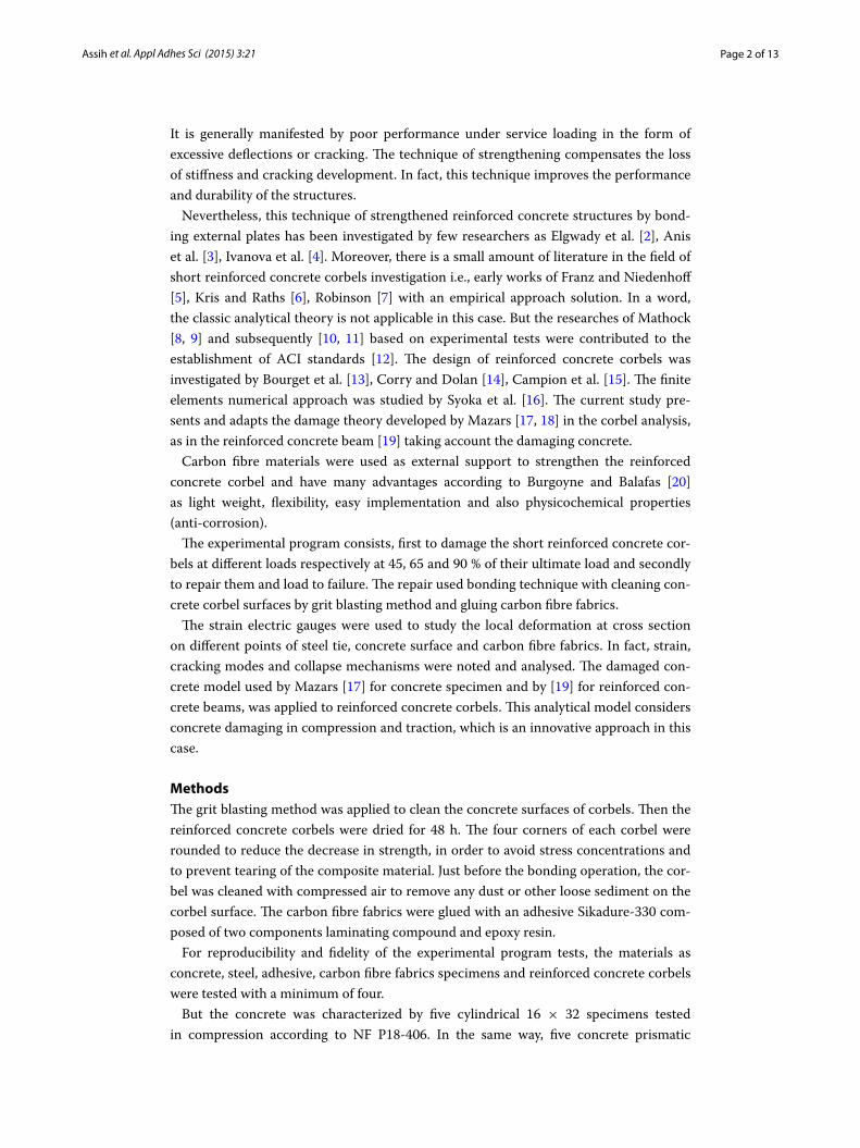
Three of the reinforced concrete corbels were subjected to a three points bending test, Fig. 1. The cracking and failure modes were reproducible with an accuracy of 7 % of ulti-mate load. With these results, the experimental program of this paper is established. The tests were carried out at ambient temperature.
Experimental model
The sizes of specimens are presented in Fig. 1. The 1000 mm long column supporting two short trapezoidal corbels cantilevering on either side is 150 mm by 300 mm in cross section. The specimens have cantilever projection length of 200 mm, with a thicknesses of 150 mm at both faces of column and free end. All reinforced concrete corbel speci-mens have the same sizes and are reinforced in the same way.
The control specimen without strengthening is denoted “C0”. The letter “C” means the Corbel and 0 (zero) marks the state without strengthening. The damaged specimens are denoted C0_45, C0_65 and C0_90 %. The names of the strengthened test specimens is CB3u, made up as follows: the first letter “C” is as previously Corbel. So, the second let-ter represents the type of strengthening (e.g. B for Bandage). Then the digit indicates the number of layers (e.g. 3). Finally the small letter denotes the type of composite material
Fig. 1 Geometry of reinforced concrete corbel
Page 4 of 13Assih et al. Appl Adhes Sci (2015) 3:21
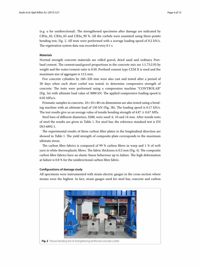
(e.g. u for unidirectional). The strengthened specimens after damage are indicated by CB3u_45, CB3u_65 and CB3u_90 %. All the corbels were soumited using three-points bending test, Fig. 2. All tests were performed with a average loading speed of 0.2 kN/s. The registration system data was recorded every 0.1 s.
Materials
Normal strength concrete materials are rolled gravel, dried sand and ordinary Port-land cement. The cement:sand:gravel proportions in the concrete mix are 1:1.73:2.93 by weight and the water/cement ratio is 0.50. Portland cement type CEM II is used and the maximum size of aggregate is 12.5 mm.
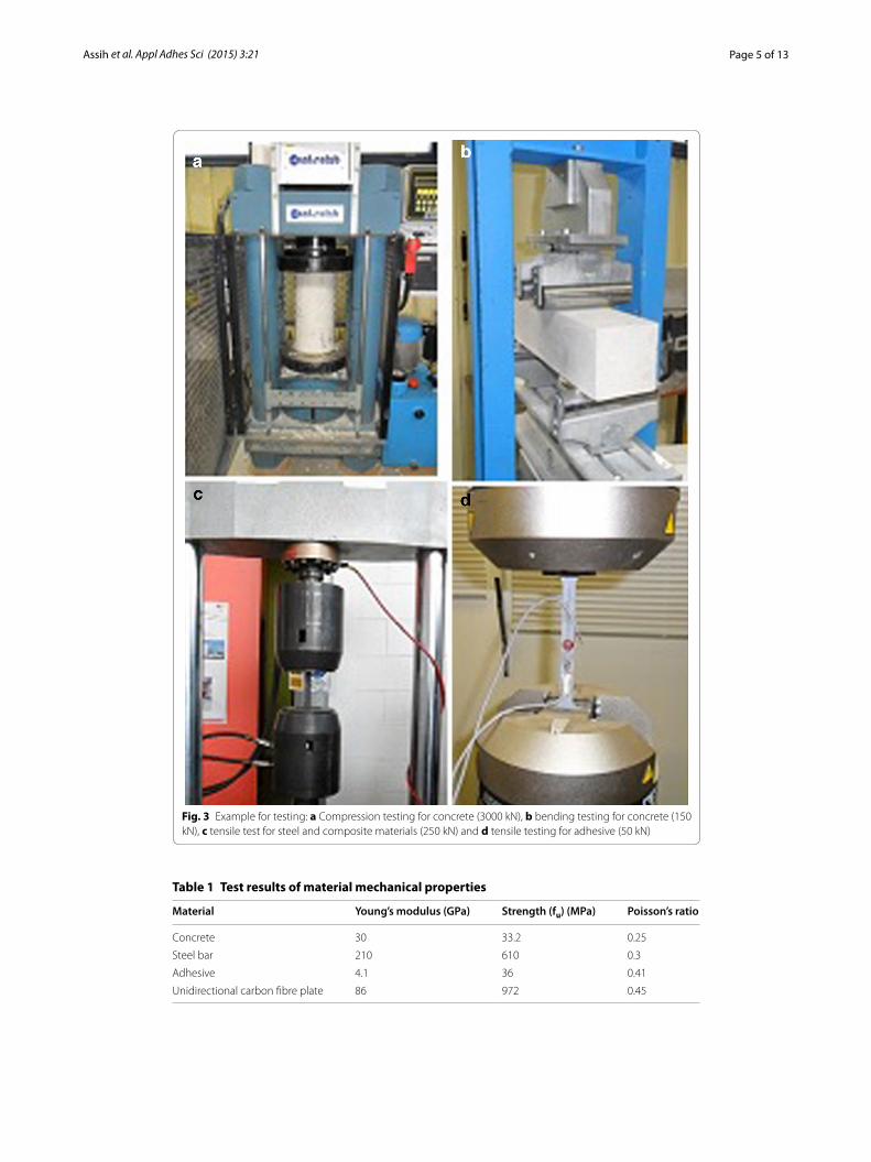
Five concrete cylinders by 160–320 mm were also cast and tested after a period of 28 days when each short corbel was tested, to determine compressive strength of concrete. The tests were performed using a compression machine “CONTROLAB” (Fig. 3a) with ultimate load value of 3000 kN. The applied compressive loading speed is 0.05 MPa/s.
Prismatic samples in concrete, 10×10×40 cm dimensions are also tested using a bend-ing machine with an ultimate load of 150 kN (Fig. 3b). The loading speed is 0.17 kN/s. The test results give us an average value of tensile bending strength of 4.87 ± 0.67 MPa.
Steel bars of different diameters, S500, were used: 6, 10 and 14 mm. After tensile tests of steel the results are given in Table 1. For steel bar, the reference standard test is EN ISO 6892-1.
The experimental results of three carbon fibre plates in the longitudinal direction are showed in Table 1. The yield strength of composite plate corresponds to the maximum ultimate stress.
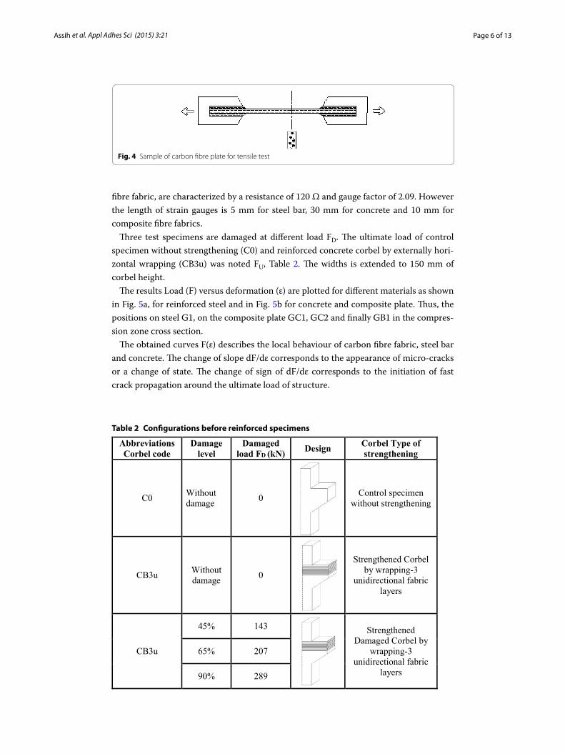
The carbon fibre fabrics is composed of 99 % carbon fibres in warp and 1 % of weft yarn in white thermoplastic fibres. The fabric thickness is 0.2 mm (Fig. 4). The composite carbon fibre fabrics have an elastic linear behaviour up to failure. The high deformation at failure is 0.8 % for the unidirectional carbon fibre fabric.
Configurations of damage study
All specimens were instrumented with strain electric gauges in the cross section where strains were the highest. In fact, strain gauges used for steel bar, concrete and carbon
Fig. 2 Flexure bending test of strengthening reinforced concrete corbel
Page 5 of 13Assih et al. Appl Adhes Sci (2015) 3:21
Fig. 3 Example for testing: a Compression testing for concrete (3000 kN), b bending testing for concrete (150 kN), c tensile test for steel and composite materials (250 kN) and d tensile testing for adhesive (50 kN)
Table 1 Test results of material mechanical properties
Material Young’s modulus (GPa) Strength (fu) (MPa) Poisson’s ratio
Concrete 30 33.2 0.25
Steel bar 210 610 0.3
Adhesive 4.1 36 0.41
Unidirectional carbon fibre plate 86 972 0.45
Page 6 of 13Assih et al. Appl Adhes Sci (2015) 3:21
fibre fabric, are characterized by a resistance of 120 Ω and gauge factor of 2.09. However the length of strain gauges is 5 mm for steel bar, 30 mm for concrete and 10 mm for composite fibre fabrics.
Three test specimens are damaged at different load FD. The ultimate load of control specimen without strengthening (C0) and reinforced concrete corbel by externally hori-zontal wrapping (CB3u) was noted FU, Table 2. The widths is extended to 150 mm of corbel height.
The results Load (F) versus deformation (ε) are plotted for different materials as shown in Fig. 5a, for reinforced steel and in Fig. 5b for concrete and composite plate. Thus, the positions on steel G1, on the composite plate GC1, GC2 and finally GB1 in the compres-sion zone cross section.
The obtained curves F(ε) describes the local behaviour of carbon fibre fabric, steel bar and concrete. The change of slope dF/dε corresponds to the appearance of micro-cracks or a change of state. The change of sign of dF/dε corresponds to the initiation of fast crack propagation around the ultimate load of structure.
Fig. 4 Sample of carbon fibre plate for tensile test
Table 2 Configurations before reinforced specimens
Abbreviations Corbel code
Damage level
Damaged load FD (kN) Design Corbel Type of
strengthening
C0 Without damage 0 Control specimen
without strengthening
CB3u Without damage 0
Strengthened Corbel by wrapping-3
unidirectional fabric layers
CB3u
45% 143 StrengthenedDamaged Corbel by
wrapping-3 unidirectional fabric
layers
65% 207
90% 289
Page 7 of 13Assih et al. Appl Adhes Sci (2015) 3:21
The concrete, steel, carbon fabric strains and cracking are raised. Most of the measures were done in a shear area at embedding section with strain gauges because the deforma-tions were of high values.
Results and discussionEffect of damage
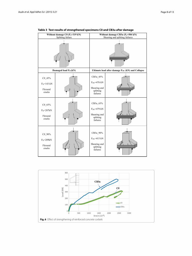
Table 3 shows the ultimate load and type of failure of the tested specimens. All corbels were tested under monotonic loading to failure in bending. The results showed that damage has an effect on the ultimate load, less than 20 % of the ultimate load to 90 % of mechanical damage.
This allows mechanical damage to work steel and composite material, although it remains well below the capacity of a composite plate. The cracking mode changes slightly in the presence of composite material. An example for the damaged corbel to 90 %, the failure occurs by shearing and splitting failure with two cracks.
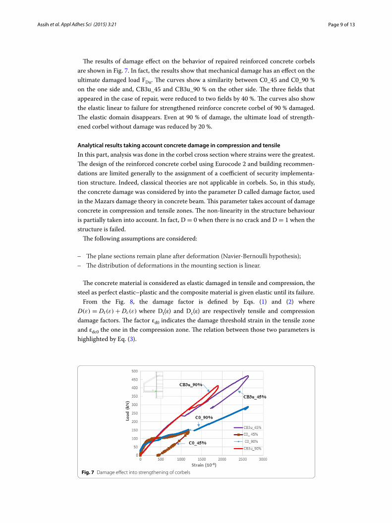
Behaviour of strengthened damaged reinforced concrete corbel
The Fig. 6 shows the effect of reinforcing into the behavior of both corbels. One of them is reinforced while the other remains unstrengthened. The two curves in Fig. 6 have two characteristic points marked by each bearing. The first landing represents the growth limit of the bending crack and the second landing is at the onset to the oblique crack and local yielding of steel. Thus, the steel yielding is compensated by the composite plate.
The first bearing is less important than in the case of strengthening due to the concrete containment by the carbon fibre fabrics. Technical strengthening increases the carrying capacity of the structure ultimate load by more than 50 % and improve the stiffness and inflexibility of specimens. Three areas were identified: elastic area, cracking propagation area limited by appeared oblique crack and the last area where it noted the opening of the oblique crack up to failure, Fig. 6.
Fig. 5 Position of strain gauges on steel bars (a) on concrete and composite plate (b) materials
Page 8 of 13Assih et al. Appl Adhes Sci (2015) 3:21
Table 3 Test results of strengthened specimens C0 and CB3u after damage
Without damage C0 (Fu=319 kN)Splitting failure
Without damage CB3u (Fu=504 kN)Shearing and splitting failures
Damaged load FD (kN) Ultimate load after damage FDU (kN) and Collapse
C0_45%
FD=143 kN
Flexural cracks
CB3u_45%
FDU=476 kN
Shearing and splitting failures
C0_65%
FD=207kN
Flexural cracks
CB3u_65%
FDU=479 kN
Shearing and splitting failures
C0_90%
FD=289kN
Flexural cracks
CB3u_90%
FDU=415 kN
Shearing and splitting failures
Fig. 6 Effect of strengthening of reinforced concrete corbels
Page 9 of 13Assih et al. Appl Adhes Sci (2015) 3:21
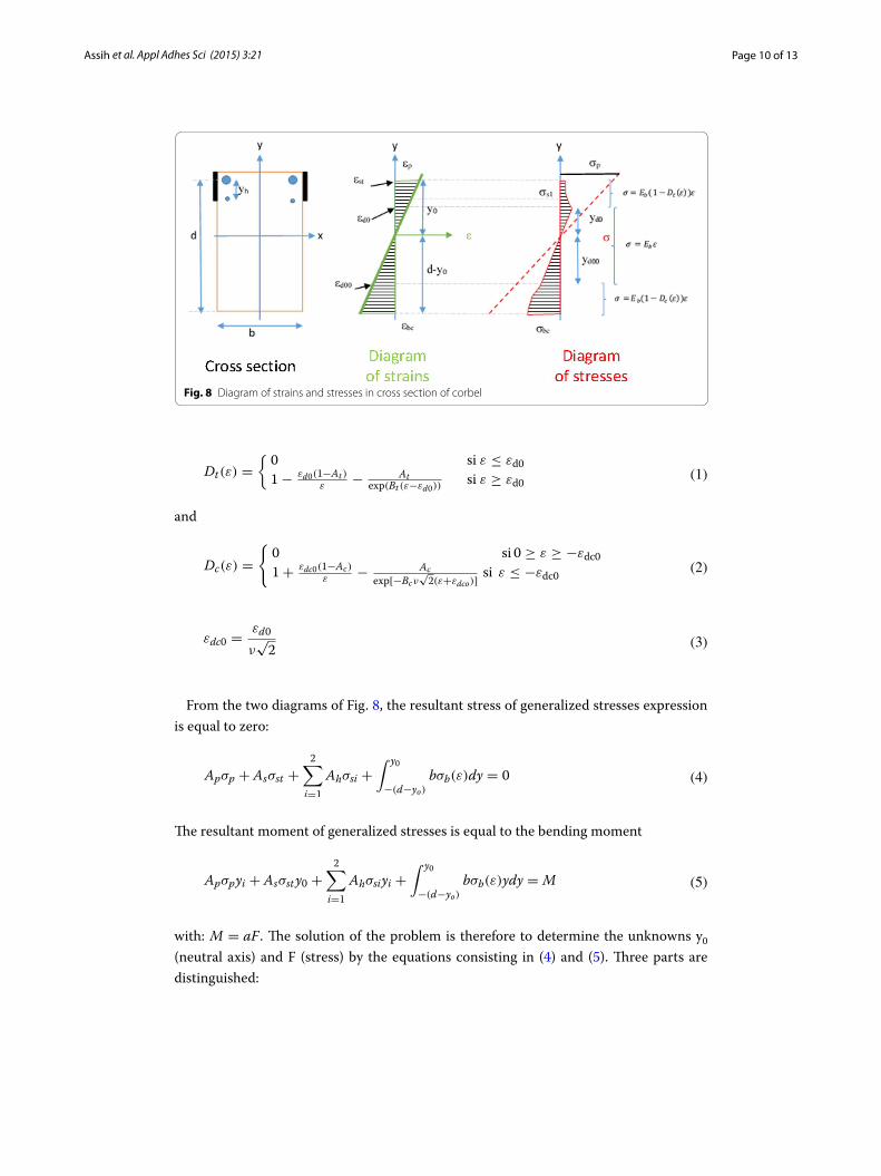
The results of damage effect on the behavior of repaired reinforced concrete corbels are shown in Fig. 7. In fact, the results show that mechanical damage has an effect on the ultimate damaged load FDu. The curves show a similarity between C0_45 and C0_90 % on the one side and, CB3u_45 and CB3u_90 % on the other side. The three fields that appeared in the case of repair, were reduced to two fields by 40 %. The curves also show the elastic linear to failure for strengthened reinforce concrete corbel of 90 % damaged. The elastic domain disappears. Even at 90 % of damage, the ultimate load of strength-ened corbel without damage was reduced by 20 %.
Analytical results taking account concrete damage in compression and tensile
In this part, analysis was done in the corbel cross section where strains were the greatest. The design of the reinforced concrete corbel using Eurocode 2 and building recommen-dations are limited generally to the assignment of a coefficient of security implementa-tion structure. Indeed, classical theories are not applicable in corbels. So, in this study, the concrete damage was considered by into the parameter D called damage factor, used in the Mazars damage theory in concrete beam. This parameter takes account of damage concrete in compression and tensile zones. The non-linearity in the structure behaviour is partially taken into account. In fact, D = 0 when there is no crack and D = 1 when the structure is failed.
The following assumptions are considered:
– The plane sections remain plane after deformation (Navier-Bernoulli hypothesis); – The distribution of deformations in the mounting section is linear.
The concrete material is considered as elastic damaged in tensile and compression, the steel as perfect elastic–plastic and the composite material is given elastic until its failure.
From the Fig. 8, the damage factor is defined by Eqs. (1) and (2) where D(ε) = Dt(ε)+ Dc(ε) where Dt(ε) and Dc(ε) are respectively tensile and compression damage factors. The factor εd0 indicates the damage threshold strain in the tensile zone and εdc0 the one in the compression zone. The relation between those two parameters is highlighted by Eq. (3).
Fig. 7 Damage effect into strengthening of corbels
Page 10 of 13Assih et al. Appl Adhes Sci (2015) 3:21
and
From the two diagrams of Fig. 8, the resultant stress of generalized stresses expression is equal to zero:
The resultant moment of generalized stresses is equal to the bending moment
with: M = aF . The solution of the problem is therefore to determine the unknowns y0 (neutral axis) and F (stress) by the equations consisting in (4) and (5). Three parts are distinguished:
(1)Dt(ε) =
0 si ε ≤ εd0
1− εd0(1−At )
ε− At
exp(Bt (ε−εd0))si ε ≥ εd0
(2)Dc(ε) =
0 si 0 ≥ ε ≥ −εdc0
1+ εdc0(1−Ac)
ε− Ac
exp[−Bcν√2(ε+εdco)]
si ε ≤ −εdc0
(3)εdc0 =εd0
ν√2
(4)Apσp + Asσst +2
∑
i=1
Ahσsi +∫ y0
−(d−yo)
bσb(ε)dy = 0
(5)Apσpyi + Asσsty0 +2
∑
i=1
Ahσsiyi +∫ y0
−(d−yo)
bσb(ε)ydy = M
Fig. 8 Diagram of strains and stresses in cross section of corbel
Page 11 of 13Assih et al. Appl Adhes Sci (2015) 3:21
Elastic linear step
The value of the damage parameter in tensile and compression zones is null in this step. And the solution of the Eqs. (4) and (5) is a closed form expressions of the applied load F (6):
where S1(y0) = n[Ashy0 − 3Ahsh] and Ash = As + 2Ah represents the total section areas of steel tie and stirrup reinforcements. n = ES
Eb is equivalency coefficient between steel
and concrete modulus.
Damage step in tensile zone
The expression of the applied load is given by Eq. (7):
where ξdt(εst) = 1
2(1−At)
(
ε2st
ε2d0
− 1
)
+Atat
1+ 2at(1+ at)−[
ε2st
ε2d0
+ 2at(εstεd0
+ at)
]
exp[ 1at(1− εst
εd0)]
Damage step in tensile and compression zone
The expression of the applied load begins by Eq. (8):
where: ξdc(εst) = 1
2(1− Ac)(
ε2bc
ε2dc0
− 1)+ Acac
1+ 2ac(1+ ac)− [ ε2bc
ε2dc0
+ 2ac(ac − εbcεdc0
)]exp[ 1
ac(1+
εbcεdc0
)]
and εbc =−(d−y0)
y0εst .
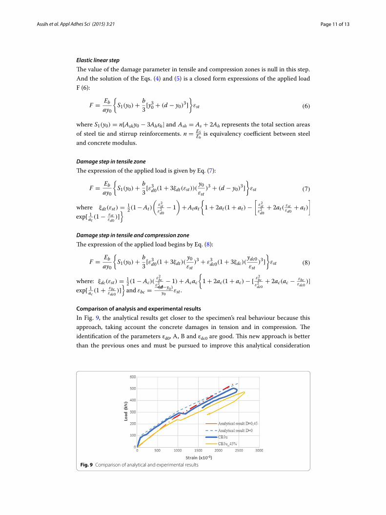
Comparison of analysis and experimental results
In Fig. 9, the analytical results get closer to the specimen’s real behaviour because this approach, taking account the concrete damages in tension and in compression. The identification of the parameters εd0, A, B and εdc0 are good. This new approach is better than the previous ones and must be pursued to improve this analytical consideration
(6)F =Eb
ay0
S1(y0)+b
3[y30 + (d − y0)
3]
εst
(7)F =Eb
ay0
S1(y0)+b
3[ε3d0(1+ 3ξdt(εst))(
y0
εst)3 + (d − y0)
3]
εst
(8)F =Eb
ay0
S1(y0)+b
3[ε3d0(1+ 3ξdt)(
y0
εst)3 + ε3dc0(1+ 3ξdc)(
ydc0
εst)3]
εst
Fig. 9 Comparison of analytical and experimental results
Page 12 of 13Assih et al. Appl Adhes Sci (2015) 3:21
taking wrapping effect. The wrapping effect was not taken into account in this analysis and mast be consider for the next study.
A model which presents the bending behaviour of strengthened reinforced concrete corbel using damage factor D is a good approach in the theoretical analysis. The results showed that the concrete damage state has a certain influence on the ultimate load of corbel. The proposed model showed also the effect of loading on the evolution and dam-age spread to the cross section. Moreover, it allows describing the three phases of the corbel’s behaviour.
ConclusionThis paper presents a study of damaged reinforced concrete corbels, where the corbels are strengthened by bonding carbon fibre fabrics. The contribution of strengthening by gluing carbon fibre fabrics on the behaviour of reinforced short concrete corbels is very significant and interesting.
The experimental program was presented to examine the behavior of specimens through the using of strain gauges. This study shows for the first time, the effect of mechanical damage on short elements of structures such as short reinforced concrete corbels. The bonding technique applied in the case of repair could be used for the reha-bilitation of structures. The test program was successful and a lot of experimental data was used in this study. The preparation of material areas and the using of strain gauges contributed to precise the analysis of the local structure behaviour.
A model of the bending behavior in the cross section of strengthened damaged short reinforced concrete corbel was presented. So, the theory of beams is combined with Mazar’s damage theory to describe the behaviour of strengthened corbel. In fact, carbon fibre fabrics resume the applied load after plasticization of steel tie. The contribution of the repair by gluing composite materials increased ultimate load from 30 to over 50 %. Mechanical damage up to 90 % has an effect on the ultimate load (less than 20 %). After being damaged, shearing appeared with two splitting failures. The type of strengthened reinforced concrete corbel failure is shearing and splitting.
AbbreviationsD: factor of damage parameter; Dt (ε): damage parameter in tensile zone; Dc(ε): damage parameter in compression zone; εdo: damage threshold strain in tensile zone; εdco: damage threshold strain in compression zone; y0: neutral axis; M: bending moment; F: applied load; Eb: concrete elastic modulus; Ap: composite plate area; As: steel area; At, Ac, Bt, Bc: are constants determined by simple tensile testing and compression; Ash: total area sections of steel and Frame; Ep: composite plate elastic modulus; Es: steel elastic modulus; FDu: ultimate damaged load; Fu: ultimate load; σp: composite plate stress; σb: concrete stress; σs: steel stress; εbc: strains of concrete in compression zone; C0: reinforced concrete corbel without strengthen; C0_45 %: reinforced concrete corbel damaged at 45 % of Fu; C0_65 %: reinforced concrete corbel damaged at 65 % of Fu; C0_90 %: reinforced concrete corbel damaged at 90 % of Fu; CB3u: strengthened reinforced con-crete corbel without damage; CB3u_45 %: strengthened reinforced concrete corbel damaged at 45 % of Fu; CB3u_65 %: strengthened reinforced concrete corbel damaged at 65 % of Fu; CB3u_90 %: strengthened reinforced concrete corbel damaged at 90 % of Fu.
Authors’ contributionsThis study is part of a wide experimental and analytical program of 30 tested corbels firstly initiated by DD, AL and JA. But in this paper, II have made substantial contribution in conception and design of reinforced concrete corbels. II carried out acquisition of data and participated in drafting the manuscript, performed the statistical analysis with JA. AL participated in test program. DD participated in damaged theory analysis. JA conceived of the study and II carried out its design and participated in coordination and helped to draft the manuscript. All authors read and approved the final manuscript.
Author details1 University of Reims Champagne-Ardenne, Chemin des Rouliers, BP 1039, 51687 Reims, France. 2 University of Chemical Technology and Metallurgy, 8 bd Kliment Ohridski, 1756 Sofia, Bulgaria.
Page 13 of 13Assih et al. Appl Adhes Sci (2015) 3:21
AcknowledgementsThis experimental study requires handling (and employees) and expensive costs. Therefore, thanks to laboratory technician for his precious help. Also thanks for the two laboratory head for their finding. And finally thanks for supplied composite and adhesive materials provided of society Sika.The last reference of publication was [21].
Competing interestsThe authors declare that they have no competing interests.
Received: 12 August 2015 Accepted: 26 November 2015
References 1. Ivanova I. Comportement mécanique de console courte en béton armé renforcée ou réparée par collage des maté-
riaux composites. France: Thèse de doctorat. Université de Reims; 2013. 2. Elgwady MA, Rabié M, Mostafa MT. Strengthening of corbels using CFRP an experimental program. Giza: Building
and Structural engineering, Cairo University; 2005. 3. Mohamad-Ali AA, Attiya MA. Experimental behavior of reinforced concrete corbels strengthened with carbon fibre
reinforced polymer strips. Basrah J Eng Sci. 2012;12:31–45. 4. Ivanova I, Assih J, Li A, Dontchev D, Delmas Y, et al. Experimental investigation into strengthened short reinforced
concrete corbels by bonding carbon fiber fabrics. J Adhes Sci Technol. 2015;29(20):2176–89. 5. Franz G, Niedenhoff H. The reinforcement of brackets and short deep beams. Trans Articl Germ Appear Beton-und
Stahlbetonbau. 1963;58(5):112–20. 6. Kriz LB, Raths CH. Connections in precast concrete structures-strength of corbels. PCI J. 1965;10(1):16–61. 7. Robinson JR. L’armature des consoles courtes. Aus theorie und praxis des stahlbetonbaues. Berlin: Wilhelm Ernst u,
Sohn; 1969. 8. Mattock AH. Discussion of the paper, Modified shear friction theory for bracket design. In: Hermansen BR, Cowan J,
editors. ACI J. 1974; 71(8):421-423. 9. Mattock AH. Design proposals for reinforced concrete corbels. PCI Journal. 1976;21(2):18–42. 10. Fattuhi NI. SFRC corbel tests. ACI Struct J. 1987;84:640–51. 11. Fattuhi NI, Hughes BP. Reinforced steel fiber concrete corbel with various shear span-to-depth-ratios. ACI Struct J.
1989;86:590–6. 12. ACI Committee 440. Guide for the design and construction of externally bonded FRP systems for strengthening
concrete structures. Farmington Hills: American Concrete Institute; 2000. 13. Bourget M, Delmas Y, Toutlemonde F. Experimental study of the behavior of reinforced high-strength concrete short
corbel. Mater Struct. 2001;34:155–62. 14. Corry RW, Dolan CW. Strengthening and repair of a column bracket using a Carbon Fiber Reinforced Polymer (CFRP)
fabric. PCI J. 2001;46(1):54-63. 15. Campione G, Mendola LL, Papia M. Flexural Behaviour of Concrete Corbels Containing Steel Fibers or Wrapped with
FRP Sheets. Mater Struct. 2005;38:617–25. 16. Syroka E, Bobinski J, Tejchman J. FE analysis of reinforced concrete corbels with enhanced continuum models. Finite
Elem Anal Des. 2011;47:1066–78. 17. Mazars J. Application de l’endommagement au comportement non linéaire et à la rupture du béton de structures.
France: Thèse de Doctorat d’Etat, Université de Paris 6; 1984. 18. Giry C. Modélisation objective de la localisation des déformations et de la fissuration dans les structures en béton
armé. France: Thèse de doctorat. Université de Grenoble; 2011. 19. Assih J. Contribution à l’étude du Renforcement et de la Réparation de Poutre en Béton Armé par Collage de
Plaques Composites en Fibres de Carbone. France: Thèse de doctorat, UFR Sciences de Reims; 1998. 20. Burgoyne C, Balafas I. Why is FRP not a financial success?. Greece: FRPRCS-8 University of Patras; 2007. 21. Ivanova I. Assih J. Static and dynamic experimental study of strengthened reinforced short concrete corbel by using
carbon fabrics, crack path in shear zone. Fracttura ed Integrità Strutturale. 2015;34:90–8.