Embed Size (px)
Citation preview
DELTA_IA-ASDA_ASDA-B2_C_EN_20150130 www.delta.com.tw/ia
Delta AC Servo System
ASDA-B2 Series
Au to ma t i o n f o r a Ch a n g i n g Wo r l d
Industrial Automation HeadquartersDelta Electronics, Inc. Taoyuan Technology Center18 Xinglong Road, Taoyuan District, Taoyuan City 33068, Taiwan (R.O.C.)TEL: 886-3-362-6301 / FAX: 886-3-371-6301
AsiaDelta Electronics (Jiangsu) Ltd.Wujiang Plant 31688 Jiangxing East Road, Wujiang Economic Development ZoneWujiang City, Jiang Su Province, People's Republic of China (Post code: 215200)TEL: 86-512-6340-3008 / FAX: 86-769-6340-7290
Delta Greentech (China) Co., Ltd.238 Min-Xia Road, Pudong District, ShangHai, P.R.C.Post code : 201209TEL: 86-21-58635678 / FAX: 86-21-58630003 Delta Electronics (Japan), Inc.Tokyo Office 2-1-14 Minato-ku Shibadaimon, Tokyo 105-0012, JapanTEL: 81-3-5733-1111 / FAX: 81-3-5733-1211
Delta Electronics (Korea), Inc.1511, Byucksan Digital Valley 6-cha, Gasan-dong, Geumcheon-gu, Seoul, Korea, 153-704TEL: 82-2-515-5303 / FAX: 82-2-515-5302
Delta Electronics Int’l (S) Pte Ltd4 Kaki Bukit Ave 1, #05-05, Singapore 417939TEL: 65-6747-5155 / FAX: 65-6744-9228
Delta Electronics (India) Pvt. Ltd.Plot No 43 Sector 35, HSIIDC Gurgaon, PIN 122001, Haryana, India TEL : 91-124-4874900 / FAX : 91-124-4874945
AmericasDelta Products Corporation (USA)Raleigh OfficeP.O. Box 12173,5101 Davis Drive, Research Triangle Park, NC 27709, U.S.A.TEL: 1-919-767-3800 / FAX: 1-919-767-8080
Delta Greentech (Brasil) S.ASao Paulo OfficeRua Itapeva, 26 - 3° andar Edificio Itapeva One-Bela Vista
01332-000-São Paulo-SP-BrazilTEL: +55 11 3568-3855 / FAX: +55 11 3568-3865
EuropeDeltronics (The Netherlands) B.V.Eindhoven OfficeDe Witbogt 15, 5652 AG Eindhoven, The Netherlands TEL: 31-40-2592850 / FAX: 31-40-2592851
*We reserve the right to change the information in this catalogue without prior notice.
Contents
Page
25
31
Optional Accessories
Accessories Combinations
7
9
12
12
13
15
172121
Features
Model Explanation
Product Line-up
Part Names and Functions
Standard Connection Examples
Selection of Regenerative Resistor
Safety Information
Servo Drive Specifications
Servo Drive Dimensions
3
5
6
Servo Motor Specifications
Servo Motor Dimensions
Speed-Torque Curve (T-N Curves)
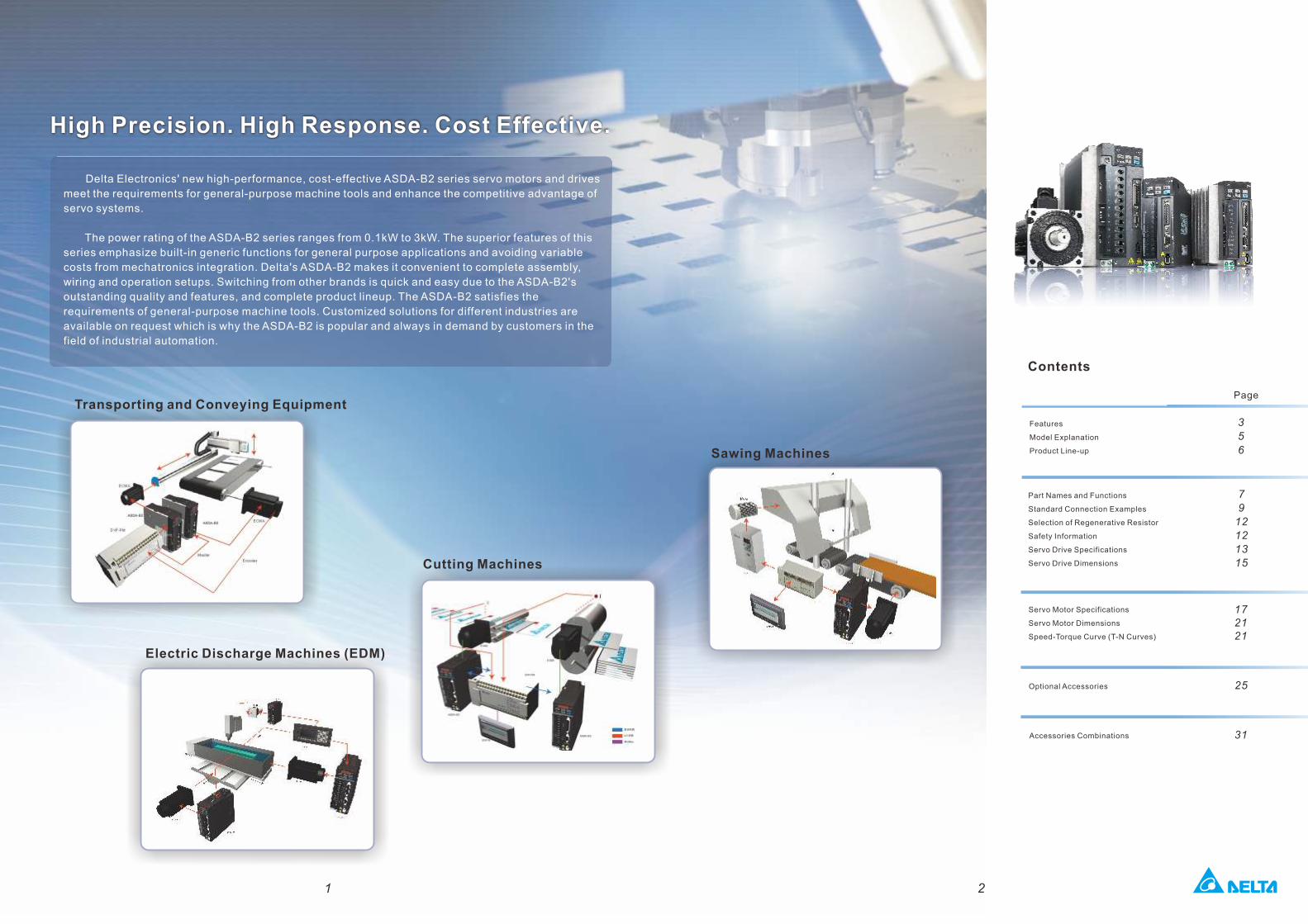
Transporting and Conveying Equipment
Electric Discharge Machines (EDM)
Cutting Machines
Sawing Machines
High Precision. High Response. Cost Effective.
Delta Electronics' new high-performance, cost-effective ASDA-B2 series servo motors and drives
meet the requirements for general-purpose machine tools and enhance the competitive advantage of
servo systems.
The power rating of the ASDA-B2 series ranges from 0.1kW to 3kW. The superior features of this
series emphasize built-in generic functions for general purpose applications and avoiding variable
costs from mechatronics integration. Delta's ASDA-B2 makes it convenient to complete assembly,
wiring and operation setups. Switching from other brands is quick and easy due to the ASDA-B2's
outstanding quality and features, and complete product lineup. The ASDA-B2 satisfies the
requirements of general-purpose machine tools. Customized solutions for different industries are
available on request which is why the ASDA-B2 is popular and always in demand by customers in the
field of industrial automation.
1 2
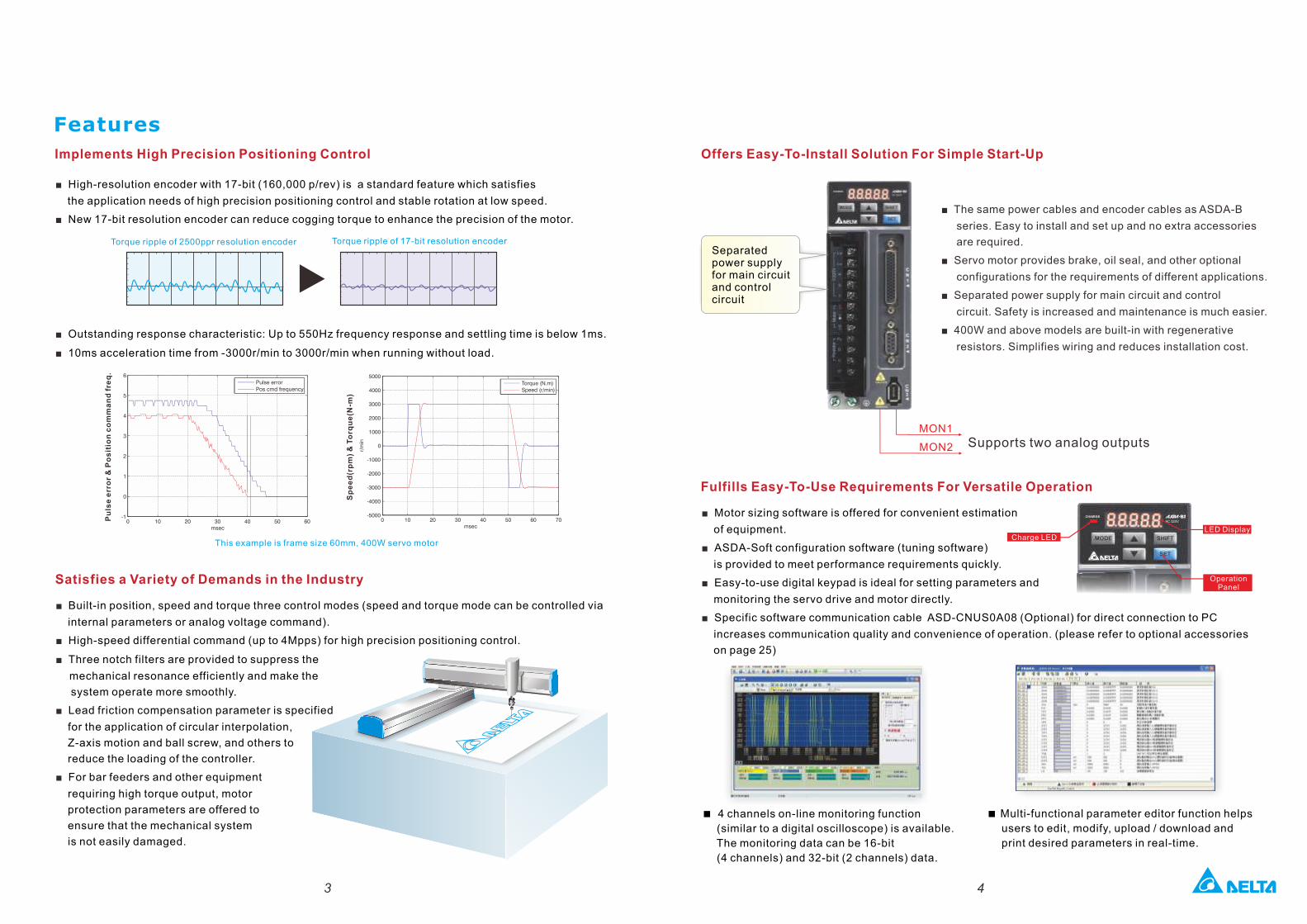
Implements High Precision Positioning Control
Features
■ High-resolution encoder with 17-bit (160,000 p/rev) is a standard feature which satisfies
the application needs of high precision positioning control and stable rotation at low speed.
■ New 17-bit resolution encoder can reduce cogging torque to enhance the precision of the motor.
■ Outstanding response characteristic: Up to 550Hz frequency response and settling time is below 1ms.
10ms acceleration time from -3000r/min to 3000r/min when running without load.■
Satisfies a Variety of Demands in the Industry
■ Built-in position, speed and torque three control modes (speed and torque mode can be controlled via
internal parameters or analog voltage command).
■ High-speed differential command (up to 4Mpps) for high precision positioning control.
■ Three notch filters are provided to suppress the
mechanical resonance efficiently and make the
system operate more smoothly.
■ Lead friction compensation parameter is specified
for the application of circular interpolation,
Z-axis motion and ball screw, and others to
reduce the loading of the controller.
For bar feeders and other equipment ■
requiring high torque output, motor
protection parameters are offered to
ensure that the mechanical system
is not easily damaged.
Torque ripple of 2500ppr resolution encoder Torque ripple of 17-bit resolution encoder
Offers Easy-To-Install Solution For Simple Start-Up
■ The same power cables and encoder cables as ASDA-B
series. Easy to install and set up and no extra accessories
are required.
■ Servo motor provides brake, oil seal, and other optional
configurations for the requirements of different applications.
■ Separated power supply for main circuit and control
circuit. Safety is increased and maintenance is much easier.
■ 400W and above models are built-in with regenerative
resistors. Simplifies wiring and reduces installation cost.
Separated power supply for main circuit and control circuit
Fulfills Easy-To-Use Requirements For Versatile Operation
■ Motor sizing software is offered for convenient estimation
of equipment.
■ ASDA-Soft configuration software (tuning software)
is provided to meet performance requirements quickly.
■ Easy-to-use digital keypad is ideal for setting parameters and
monitoring the servo drive and motor directly.
■ Specific software communication cable ASD-CNUS0A08 (Optional) for direct connection to PC
increases communication quality and convenience of operation. (please refer to optional accessories
on page 25)
Charge LEDLED Display
Operation Panel
<�4 channels on-line monitoring function
(similar to a digital oscilloscope) is available.
The monitoring data can be 16-bit
(4 channels) and 32-bit (2 channels) data.
< Multi-functional parameter editor function helps
users to edit, modify, upload / download and
print desired parameters in real-time.
43
Supports two analog outputsMON1
MON2
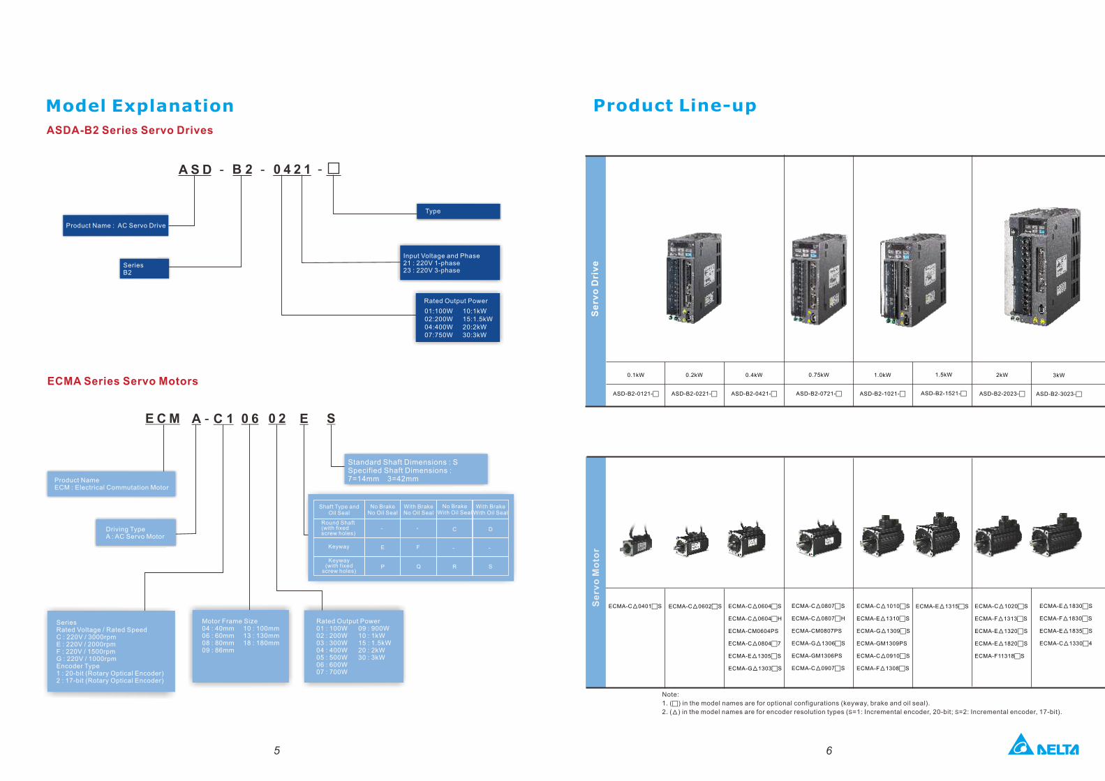
Model Explanation
ASDA-B2 Series Servo Drives
Product Name : AC Servo Drive
SeriesB2
Rated Output Power
01:100W02:200W04:400W07:750W
Input Voltage and Phase21 : 220V 1-phase23 : 220V 3-phase
Type
E C M - C 1 0 6 0 2 EA S
Product NameECM : Electrical Commutation Motor
Standard Shaft Dimensions : SSpecified Shaft Dimensions : 7=14mm 3=42mm
Driving TypeA : AC Servo Motor
SeriesRated Voltage / Rated SpeedC : 220V / 3000rpmE : 220V / 2000rpmF : 220V / 1500rpmG : 220V / 1000rpmEncoder Type1 : 20-bit (Rotary Optical Encoder)2 : 17-bit (Rotary Optical Encoder)
Motor Frame Size 04 : 40mm 10 : 100mm 06 : 60mm 13 : 130mm 08 : 80mm 18 : 180mm09 : 86mm
Rated Output Power01 : 100W 09 : 900W02 : 200W 10 : 1kW 03 : 300W 15 : 1.5kW 04 : 400W 20 : 2kW05 : 500W 30 : 3kW06 : 600W 07 : 700W
Shaft Type and Oil Seal
Round Shaft(with fixedscrew holes)
No BrakeNo Oil Seal
With BrakeNo Oil Seal
No BrakeWith Oil Seal
With BrakeWith Oil Seal
10:1kW15:1.5kW20:2kW30:3kW
Keyway
ECMA Series Servo Motors
Keyway (with fixed
screw holes)
Product Line-up
5 6
1.5kW
ASD-B2-1521-c
0.1kW
ASD-B2-0121-c
0.2kW
ASD-B2-0221-c
0.4kW
ASD-B2-0421-c
1.0kW
ASD-B2-1021-c
2kW
ASD-B2-2023-c
3kW
ASD-B2-3023-c
0.75kW
ASD-B2-0721-c
Se
rvo
Dri
ve
Se
rvo
Mo
tor
Note:
1. ( ) in the model names are for optional configurations (keyway, brake and oil seal).c
2. ( ) in the model names are for encoder resolution types ( =1: Incremental encoder, 20-bit; =2: Incremental encoder, 17-bit).▲ S S
A S D - B 2 0 4 2 1 - -
ECMA-C 0401cS▲ ECMA-C 0604cS▲
ECMA-C 0604cH▲
ECMA-CM0604PS
ECMA-C 0804c7▲
ECMA-E 1305cS▲
ECMA-G 1303cS▲
ECMA-C 0807cS▲
ECMA-C 0807cH▲
ECMA-CM0807PS
ECMA-G 1306cS▲
ECMA-GM1306PS
ECMA-C 0907cS▲
ECMA-C 1010cS▲
ECMA-E 1310cS▲
ECMA-G 1309cS▲
ECMA-GM1309PS
ECMA-C 0910cS▲
ECMA-F 1308cS▲
ECMA-E 1315cS▲ ECMA-E 1830cS ▲
ECMA-F 1830cS ▲
ECMA-E 1835cS▲
ECMA-C 1330c4▲
ECMA-C 0602cS▲ ECMA-C 1020cS▲
ECMA-F 1313cS▲
ECMA-E 1320cS▲
ECMA-E 1820cS▲
ECMA-F11318cS
-
E
P
-
F
Q
C
-
R
D
-
S
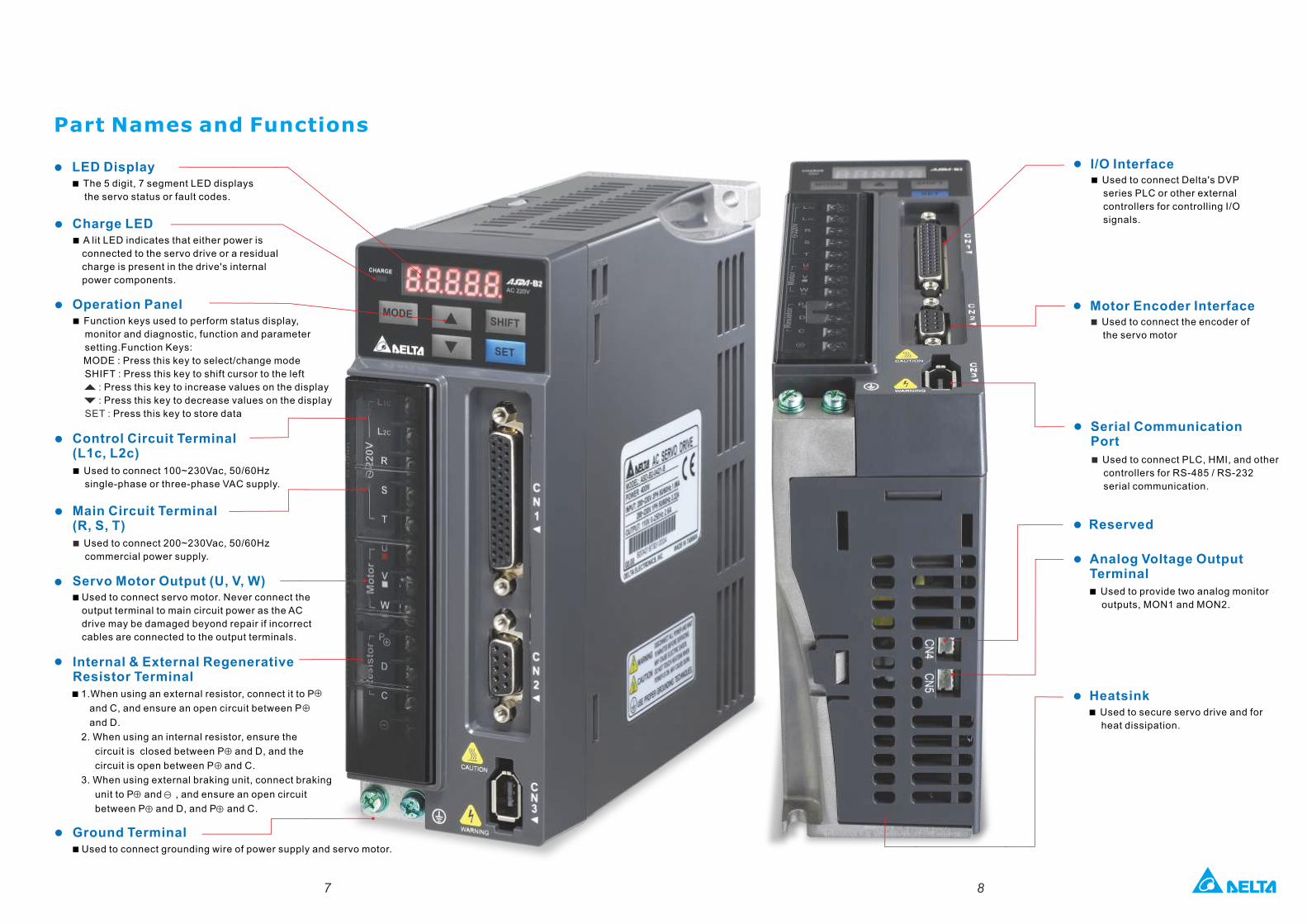
Part Names and Functions
< The 5 digit, 7 segment LED displays
the servo status or fault codes.
<1.When using an external resistor, connect it to P
and C, and ensure an open circuit between P
and D.
2. When using an internal resistor, ensure the
circuit is closed between P and D, and the
circuit is open between P and C.
3. When using external braking unit, connect braking
unit to P and , and ensure an open circuit
between P and D, and P and C.
<Used to connect servo motor. Never connect the
output terminal to main circuit power as the AC
drive may be damaged beyond repair if incorrect
cables are connected to the output terminals.
LED Display
Internal & External RegenerativeResistor Terminal
Servo Motor Output (U, V, W)
< A lit LED indicates that either power is
connected to the servo drive or a residual
charge is present in the drive's internal
power components.
Charge LED
< Function keys used to perform status display,
monitor and diagnostic, function and parameter
setting.Function Keys:
MODE : Press this key to select/change mode
SHIFT : Press this key to shift cursor to the left
: Press this key to increase values on the display
: Press this key to decrease values on the display
SET : Press this key to store data
Operation Panel
< Used to connect 100~230Vac, 50/60Hz
single-phase or three-phase VAC supply.
Control Circuit Terminal (L1c, L2c)
< Used to connect 200~230Vac, 50/60Hz
commercial power supply.
Main Circuit Terminal (R, S, T)
Ground Terminal <Used to connect grounding wire of power supply and servo motor.
7 8
< Used to secure servo drive and for
heat dissipation.
< Used to provide two analog monitor
outputs, MON1 and MON2.
Analog Voltage Output Terminal
Heatsink
< Used to connect Delta's DVP
series PLC or other external
controllers for controlling I/O
signals.
I/O Interface
< Used to connect the encoder of
the servo motor
Motor Encoder Interface
< Used to connect PLC, HMI, and other
controllers for RS-485 / RS-232
serial communication.
Serial Communication Port
Reserved
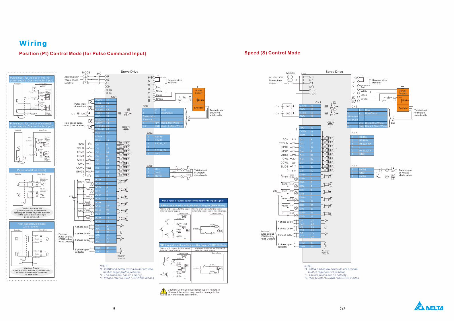
PNP transistor with multiple emitter fingers(SOURCE Mode)
Wiring
Caution: Because this photocoupler is a unidirectional
optocoupler, please pay close attention on the current direction of input
pulse command.
Pulse input (Line driver)
Pulse input, for the use of external power supply (Open-collector input)
Pulse input, for the use of internal power supply (Open-collector input)
High-speed pulse input (Line receiver)
Caution: Ensure that the ground terminal of the controller
and the servo drive are connected to each other.
Position (Pt) Control Mode (for Pulse Command Input)
AC 200/230V
Three-phase
50/60Hz
/SIGN
SIGN
/PULSE
PULSE
37
39
41
43
RST
L2C
L1C
P
D
C
U
V
WGreen
MCCB
CN1
MC
RS485-
RS485+
RS232_RX
-
RS232_TX
GND
CN3
Pulse input(Line driver)
Twisted-pair or twisted-shield cable
CN2
High-speed pulse input (Line receiver)
SG
Encoder
Power Supply
-
10kΩ10 V
Red
White
Black
*1
10kΩ
10kΩ
Encoder pulse output (PG Dividing Ratio Output)
Servo Drive
Blue
Blue/Black
-
-
Red & Red/White
Black & Black/White
CN5
V
V
10kΩ
10kΩ
SG
DI1
DI2
DI3
DI4
DI5
DI6
DI7
DI8
DI9
SON
CCLR
TCM0
TCM1
ARST
CWL
CCWL
EMGS
0
DC24V*3
24V
1.5kΩSRDY
ZSPD
ALRM
TPOS
1.5kΩ
1.5kΩ
1.5kΩ
1.5kΩ
OA
/OA
OB
/OB
OZ
/OZ
A phase pulse
B phase pulse
Z phase pulse
Max. output current 3A voltage 50V
44
19
OCZ
GNDZ phase open collector
*3
9
10
34
8
33
32
31
30
12
0
Brake24V
BRKR
(
EMGS
*2
/HSIGN
HSIGN
/HPULSE
HPULSE
40
42
36
38
18
19
T-REF
GND
17
11
14
VDD
COM+
COM-
DO1+
DO1-
DO2+
DO2-
DO3+
DO3-
DO4+
DO4-
DO5+
DO5-
DO6+
DO6-
7
6
5
4
3
2
1
26
28
27
16
15
21
22
25
23
13
24
T+
T -
-
-
+5V
GND
4
5
Reserved
Reserved
8
6,7
6
5
4
3
2
1
1
2
3
MON1
GND
MON2
AC 200/230V
Three-phase
50/60Hz
RST
L2C
L1C
P
D
C
U
V
W
MCCB MC
-
*1
CN1
20
19
V-REF
GND
10kΩ10 V 10kΩ
10kΩ
18
19
T-REF
GND10kΩ10 V 10kΩ
10kΩ
CN3
CN2
SG
CN5
V
V
10kΩ
10kΩ
SG
24V
BRKR
(
EMGS
*2
DI1
DI2
DI3
DI4
DI5
DI6
DI7
DI8
DI9
SON
TRQLM
SPD0
SPD1
ARST
CWL
CCWL
EMGS
0
DC24V
24V
1.5kΩSRDY
ZSPD
TSPD
ALRM
BRKR
1.5kΩ
1.5kΩ
1.5kΩ
1.5kΩ
*3
VDD
COM+
COM-
9
10
34
8
33
32
31
30
12
0
NPN transistor with multiple emitter fingers (SINK Mode)
Servo Drive
VDD
DC24V
COM+
COM-
SON
C
E
B
Approx.4.7kΩ
Approx.4.7kΩ
COM+
SON
DC24V
VDD
DC24V
COM+
COM-
SON
E
C
BRCOM+
SON
DC24V
WARNING
NOTE: *1. 200W and below drives do not provide built-in regenerative resistor.*2. The brake coil has no polarity.*3. Please refer to SINK / SOURCE modes
Speed (S) Control Mode
17
11
14
DO1+
DO1-
DO2+
DO2-
DO3+
DO3-
DO4+
DO4-
DO5+
DO5-
DO6+
DO6-
7
6
5
4
3
2
1
26
28
27
16
15
21
22
25
23
13
24
OA
/OA
OB
/OB
OZ
/OZ
44
19
OCZ
GND
Wiring of DI signal, for the use of internal power supply
T+
T -
-
-
+5V
GND
6
5
4
3
2
1
RS485-
RS485+
RS232_RX
-
RS232_TX
GND
1
2
3
MON1
GND
MON2
Use a relay or open-collector transistor to input signal
Twisted-pair or twisted-shield cable
RegenerativeResistor
Caution: Do not use dual power supply. Failure to observe this caution may result in damage to the servo drive and servo motor.
Wiring of DI signal, for the use of external power supply, inductive load
Servo Drive
Wiring of DI signal, for the use of internal power supply
Wiring of DI signal, for the use of external power supply
Servo Drive Servo Drive
Approx.4.7kΩ
Approx.4.7kΩ
Approx.4.7kΩ
Servo Drive
Green
Red
White
Black
RegenerativeResistor
Twisted-pair or twisted-shield cable
Encoder
Power Supply
Brake
Blue
Blue/Black
-
-
Red & Red/White
Black & Black/White
4
5
Reserved
Reserved
8
6,7
Twisted-pair or twisted-shield cable
A phase pulse
B phase pulse
Z phase pulse
Z phase open collector
Max. output current 3A voltage 50V
Encoder pulse output (PG Dividing Ratio Output)
Controller Servo Drive
Approx.
2kΩ
Controller Servo Drive
/SIGN
SG
39
37
/PULSE
PULSE 43
41
Controller Servo Drive
Max. input pulse frequencyis 500kpps
Max. input pulse frequencyis 500kpps
SIGN 51Ω
51Ω
51Ω
51Ω
42 HSIGN
40 /HSIGN
38 HPULSE
36 /HPULSE
19 GNDGND
SG
Controller Servo Drive
2kΩ
2kΩ
2kΩ
2kΩ
100kΩ
100Ω
NOTE: *1. 200W and below drives do not provide built-in regenerative resistor.*2. The brake coil has no polarity.*3. Please refer to SINK / SOURCE modes
9 10
5kΩ
5kΩ
5kΩ
5kΩ
5kΩ
5kΩ
5kΩ
5kΩ
5kΩ
5kΩ
5kΩ
5kΩ
5kΩ
5kΩ
5kΩ
5kΩ
5kΩ
5kΩ
SG
/PULSE
COM-
41
14
37
PULL_HI
/SIGN
35
VDD 17DC24V
75Ω
75Ω
75Ω
75Ω
2kΩ
2kΩ
Max. input pulse frequencyis 200kpps
Max. input pulse frequencyis 200kpps
Approx.
2kΩ
-
+
SG
DC24V
PULL_HI 35
/SIGN 37
/PULSE 41
75Ω
75Ω
75Ω
75Ω
2kΩ
2kΩ
Max. input pulse frequencyis 200kpps
Max. input pulse frequencyis 200kpps
Approx.
2kΩ
Approx.4.7kΩ
1.5kΩ
1.5kΩ
Approx.
2kΩ
RST
L2C
L1C
MCCB MC
-
*1
CN1
10kΩ10 V 10kΩ
10kΩ
10kΩ10 V 10kΩ
10kΩ
CN3
CN2
SG
CN5
V
V
10kΩ
10kΩSG
24V
BRKR
(
EMGS
*2
SON
SPDLM
TCM0
TCM1
ARST
CWL
CCWL
EMGS
0
DC24V
24V
1.5kΩSRDY
ZSPD
TSPD
ALRM
BRKR
1.5kΩ
1.5kΩ
1.5kΩ
1.5kΩ
OA
/OA
OB
/OB
OZ
/OZ
44
19
OCZ
GND
*3
1.5kΩ0
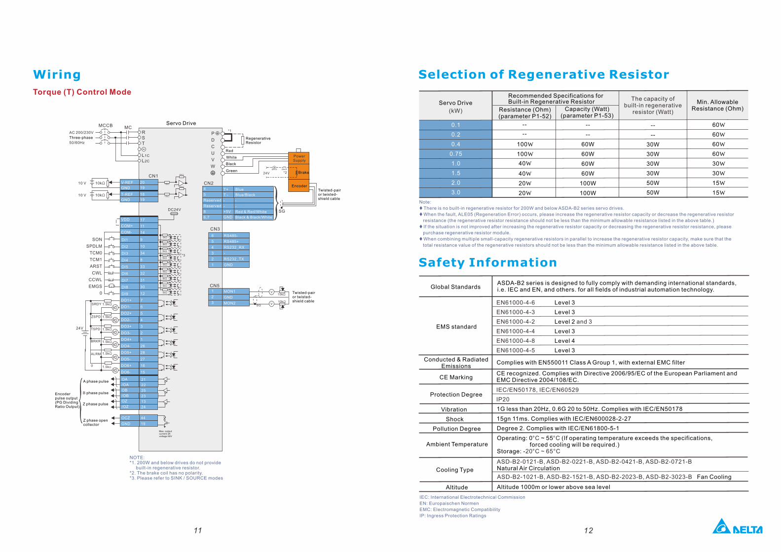
Torque (T) Control Mode
20
19
V-REF
GND
18
19
T-REF
GND
DI1
DI2
DI3
DI4
DI5
DI6
DI7
DI8
DI9
17
11
14
VDD
COM+
COM-
9
10
34
8
33
32
31
30
12
7
6
5
4
3
2
1
26
28
27
16
15
DO1+
DO1-
DO2+
DO2-
DO3+
DO3-
DO4+
DO4-
DO5+
DO5-
DO6+
DO6-
21
22
25
23
13
24
T+
T -
-
-
+5V
GND
6
5
4
3
2
1
RS485-
RS485+
RS232_RX
-
RS232_TX
GND
1
2
3
MON1
GND
MON2
..
Selection of Regenerative Resistor
Servo Drive
(kW)
0.1
0.2
0.4
0.75
1.0
1.5
2.0
3.0
Resistance (Ohm) (parameter P1-52)
--
--
100W
100W
40W
40W
20W
20W
Capacity (Watt) (parameter P1-53)
--
--
60W
60W
60W
60W
100W
100W
Recommended Specifications for Built-in Regenerative Resistor
60W
60W
60W
60W
30W
30W
15W
15W
Min. Allowable Resistance (Ohm)
Note:
t There is no built-in regenerative resistor for 200W and below ASDA-B2 series servo drives.
t When the fault, ALE05 (Regeneration Error) occurs, please increase the regenerative resistor capacity or decrease the regenerative resistor
resistance (the regenerative resistor resistance should not be less than the minimum allowable resistance listed in the above table.)
t If the situation is not improved after increasing the regenerative resistor capacity or decreasing the regenerative resistor resistance, please
purchase regenerative resistor module.
t When combining multiple small-capacity regenerative resistors in parallel to increase the regenerative resistor capacity, make sure that the
total resistance value of the regenerative resistors should not be less than the minimum allowable resistance listed in the above table.
Safety Information
ASDA-B2 series is designed to fully comply with demanding international standards, i.e. IEC and EN, and others. for all fields of industrial automation technology.Global Standards
EN61000-4-6 Level 3
EN61000-4-3 Level 3
EN61000-4-2 and 3Level 2
EN61000-4-4 Level 3
EN61000-4-8 Level 4
EN61000-4-5 Level 3
EMS standard
Conducted & Radiated Emissions
Complies with EN550011 Class A Group 1, with external EMC filter
CE MarkingCE recognized. Complies with Directive 2006/95/EC of the European Parliament and EMC Directive 2004/108/EC.
IEC/EN50178, IEC/EN60529
IP20Protection Degree
Vibration 1G less than 20Hz, 0.6G 20 to 50Hz. Complies with IEC/EN50178
Shock 15gn 11ms. Complies with IEC/EN600028-2-27
Pollution Degree Degree 2. Complies with IEC/EN61800-5-1
Ambient Temperature Operating: 0 ~ 55 (If operating temperature exceeds the specifications,°C °C forced cooling will be required.)Storage: -20°C ~ 65°C
ASD-B2-0121-B, ASD-B2-0221-B, ASD-B2-0421-B, ASD-B2-0721-B Natural Air CirculationCooling TypeASD-B2-1021-B, ASD-B2-1521-B, ASD-B2-2023-B, ASD-B2-3023-B Fan Cooling
Altitude Altitude 1000m or lower above sea level
IEC: International Electrotechnical Commission
EN: Europaischen Normen
EMC: Electromagnetic Compatibility
IP: Ingress Protection Ratings
Servo Drive
AC 200/230V
Three-phase
50/60Hz
Encoder pulse output (PG Dividing Ratio Output)
A phase pulse
B phase pulse
Z phase pulse
Z phase open collector
Max. output current 3A voltage 50V
Green
Twisted-pair or twisted-shield cable
Encoder
Power Supply
Red
White
Black
Brake
RegenerativeResistor
Blue
Blue/Black
-
-
Red & Red/White
Black & Black/White
4
5
Reserved
Reserved
8
6,7
Twisted-pair or twisted-shield cable
NOTE: *1. 200W and below drives do not provide built-in regenerative resistor.*2. The brake coil has no polarity.*3. Please refer to SINK / SOURCE modes
11 12
5kΩ
5kΩ
5kΩ
5kΩ
5kΩ
5kΩ
5kΩ
5kΩ
5kΩ
--
--
30W
30W
30W
30W
50W
50W
The capacity of built-in regenerative
resistor (Watt)
P
D
C
U
V
W
Wiring
13 14
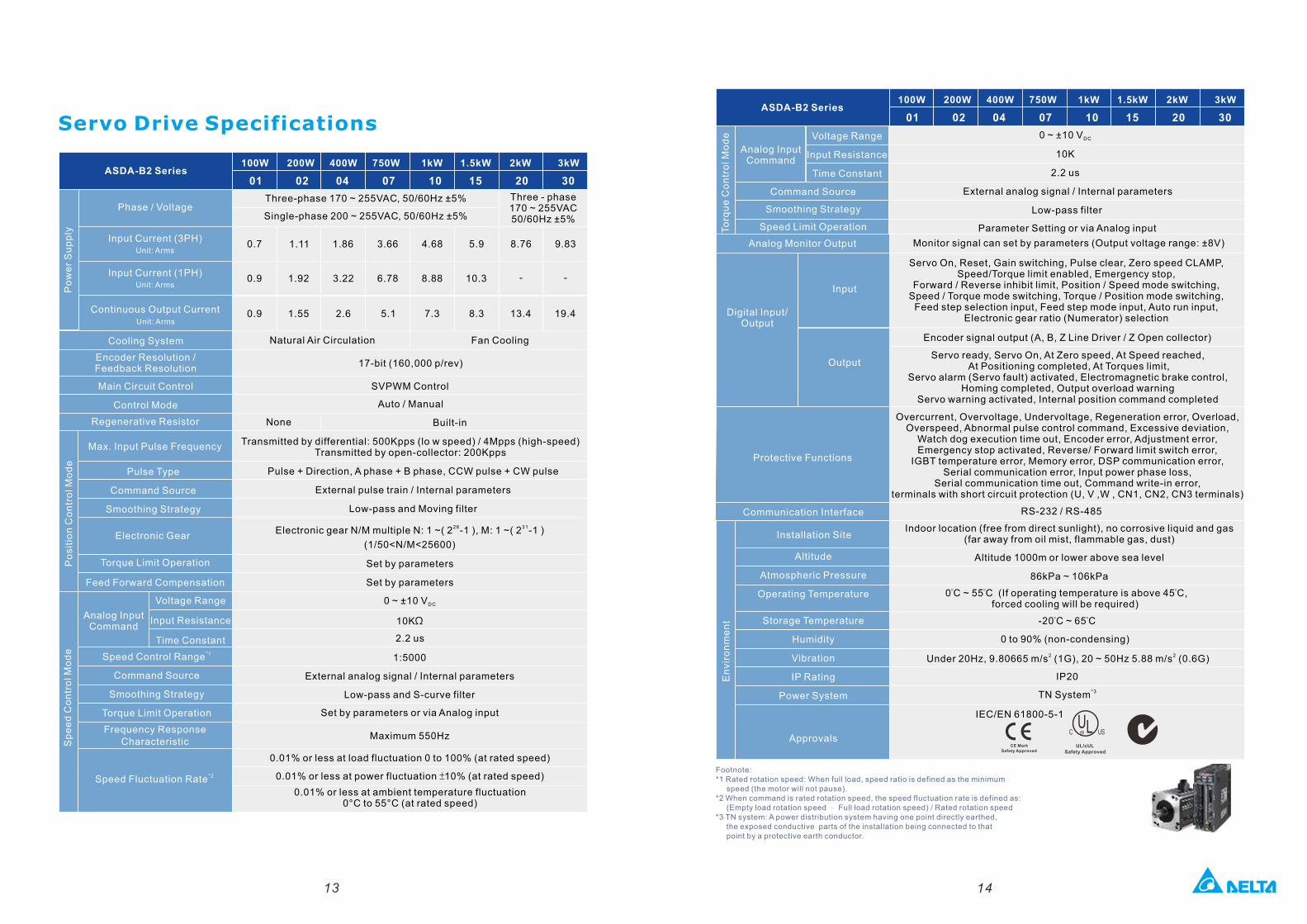
ASDA-B2 Series
Cooling System
Encoder Resolution / Feedback Resolution
Main Circuit Control
Control Mode
Regenerative Resistor
Pulse Type
Command Source
Smoothing Strategy
Max. Input Pulse Frequency
Electronic Gear
Torque Limit Operation
Feed Forward Compensation
Po
sit
ion C
on
tro
l Mo
de
Voltage Range
Input Resistance
Time Constant*1Speed Control Range
Command Source
Smoothing Strategy
Torque Limit Operation
Frequency Response Characteristic
Voltage Range
Input Resistance
Time Constant
Analog Input Command
Command Source
Smoothing Strategy
Speed Limit Operation
100W 200W 400W 750W 1kW 1.5kW 2kW 3kW
01 02 04 07 10 15 20 30
Natural Air Circulation Fan Cooling
17-bit (160 000 p/rev),
SVPWM Control
Auto / Manual
None Built-in
Transmitted by differential: 500Kpps (lo w speed) / 4Mpps (high-speed)Transmitted by open-collector: 200Kpps
Pulse + Direction, A phase + B phase, CCW pulse + CW pulse
External pulse train / Internal parameters
Low-pass and Moving filter
26 31Electronic gear N/M multiple N: 1 ~( 2 -1 ), M: 1 ~( 2 -1 )
(1/50<N/M<25600)
Set by parameters
Set by parameters
0 ~ ±10 V DC
10KΩ
2.2 us
1:5000
External analog signal / Internal parameters
Low-pass and S-curve filter
Set by parameters or via Analog input
Maximum 550Hz
0.01% or less at load fluctuation 0 to 100% (at rated speed)
0.01% or less at power fluctuation ±10% (at rated speed)
0.01% or less at ambient temperature fluctuation 0°C to 55°C (at rated speed)
0 ~ ±10 V DC
10K
2.2 us
External analog signal / Internal parameters
Low-pass filter
Parameter Setting or via Analog input
Analog Input Command
Sp
ee
d C
on
tro
l Mo
de
To
rqu
e C
on
tro
l Mo
de
Servo Drive Specifications
*2Speed Fluctuation Rate
Overcurrent, Overvoltage, Undervoltage, Regeneration error, Overload, Overspeed, Abnormal pulse control command, Excessive deviation,
Watch dog execution time out, Encoder error, Adjustment error, Emergency stop activated, Reverse/ Forward limit switch error,
IGBT temperature error, Memory error, DSP communication error, Serial communication error, Input power phase loss,
Serial communication time out, Command write-in error, terminals with short circuit protection (U, V ,W , CN1, CN2, CN3 terminals)
Encoder signal output (A, B, Z Line Driver / Z Open collector)
Monitor signal can set by parameters (Output voltage range: ±8V)
RS-232 / RS-485
Indoor location (free from direct sunlight), no corrosive liquid and gas (far away from oil mist, flammable gas, dust)
Altitude 1000m or lower above sea level
86kPa ~ 106kPa
0°C ~ 55°C (If operating temperature is above 45°C, forced cooling will be required)
0 to 90% (non-condensing)
2 2Under 20Hz, 9.80665 m/s (1G), 20 ~ 50Hz 5.88 m/s (0.6G)
IP20
*3TN System
ASDA-B2 Series100W 200W 400W 750W 1kW 1.5kW 2kW 3kW
01 02 04 07 10 15 20 30
Analog Monitor Output
Digital Input/Output
Input
Output
Communication Interface
Installation Site
Altitude
Atmospheric Pressure
Operating Temperature
Storage Temperature
Humidity
Vibration
IP Rating
Power System
En
vir
on
me
nt
Approvals
Footnote:*1 Rated rotation speed: When full load, speed ratio is defined as the minimum speed (the motor will not pause).*2 When command is rated rotation speed, the speed fluctuation rate is defined as: (Empty load rotation speed – Full load rotation speed) / Rated rotation speed*3 TN system: A power distribution system having one point directly earthed, the exposed conductive parts of the installation being connected to that point by a protective earth conductor.
Servo On, Reset, Gain switching, Pulse clear, Zero speed CLAMP, Speed/Torque limit enabled, Emergency stop,
Forward / Reverse inhibit limit, Position / Speed mode switching, Speed / Torque mode switching, Torque / Position mode switching,
Feed step selection input, Feed step mode input, Auto run input, Electronic gear ratio (Numerator) selection
Servo ready, Servo On, At Zero speed, At Speed reached, At Positioning completed, At Torques limit,
Servo alarm (Servo fault) activated, Electromagnetic brake control, Homing completed, Output overload warning
Servo warning activated, Internal position command completed
Protective Functions
0.9 1.55 2.6 5.1 7.3 8.3 13.4 19.4
0.7 1.11 1.86 3.66 4.68 5.9 8.76 9.83
0.9 1.92 3.22 6.78 8.88 10.3 - -
Input Current (3PH)Unit: Arms
Input Current (1PH)Unit: Arms
Phase / Voltage
Continuous Output CurrentUnit: Arms
Po
we
r S
up
ply
Three-phase 170 ~ 255VAC , 50/60Hz ±5%
Single-phase 200 ~ 255VAC , 50/60Hz ±5%
Three - phase 170 ~ 255VAC50/60Hz ±5%
IEC/EN 61800-5-1
-20°C ~ 65°C
15 16
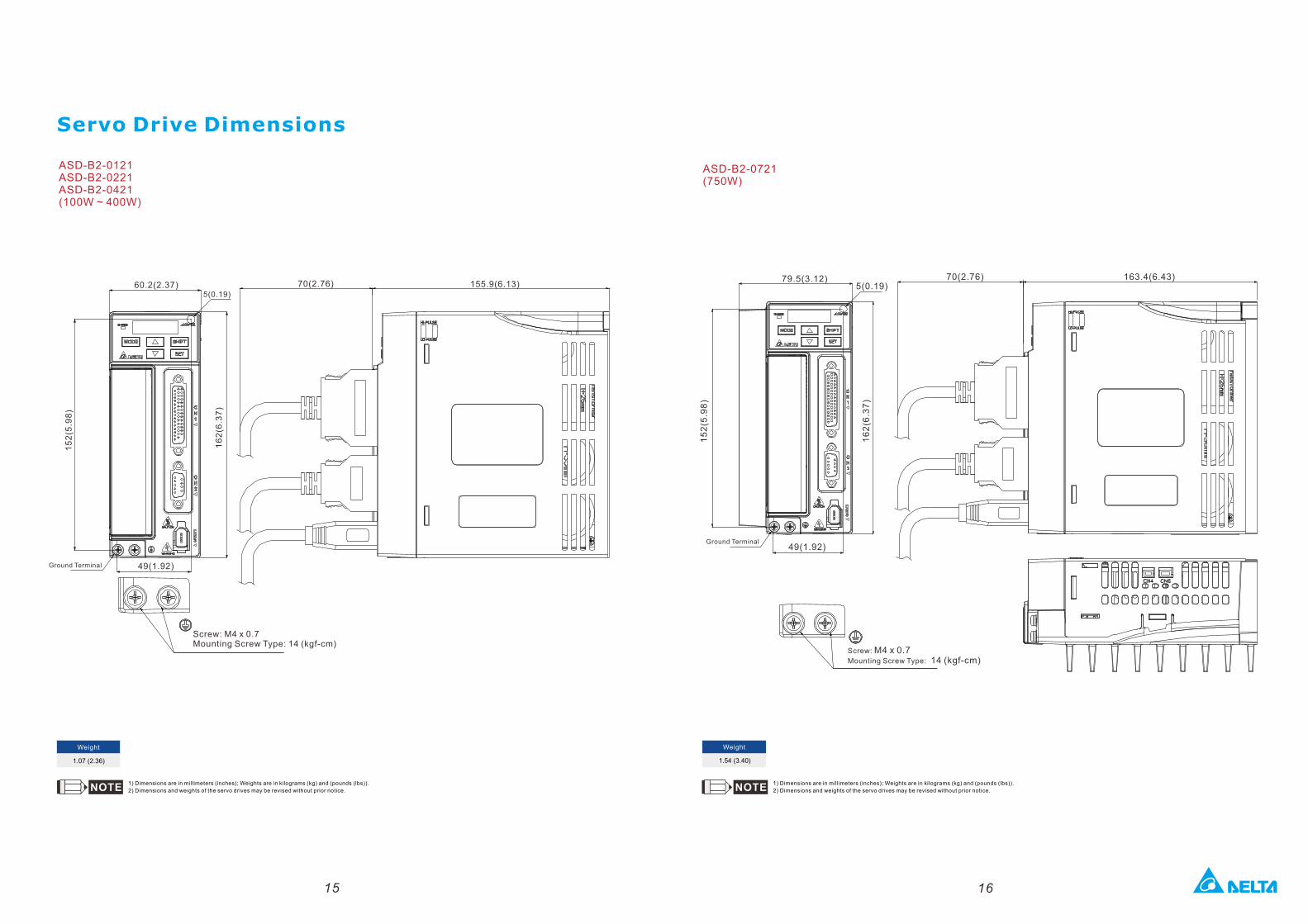
1.54 (3.40)
Weight
1) Dimensions are in millimeters (inches); Weights are in kilograms (kg) and (pounds (lbs)).
2) Dimensions and weights of the servo drives may be revised without prior notice.
1.07 (2.36)
Weight
Screw: M4 x 0.7Mounting Screw Type: 14 (kgf-cm)
79.5(3.12)5(0.19)
70(2.76) 163.4(6.43)
49(1.92)
15
2(5
.98
)
16
2(6
.37
)
Servo Drive Dimensions
1) Dimensions are in millimeters (inches); Weights are in kilograms (kg) and (pounds (lbs)).
2) Dimensions and weights of the servo drives may be revised without prior notice.
ASD-B2-0121 ASD-B2-0221 ASD-B2-0421 (100W ~ 400W)
ASD-B2-0721 (750W)
Ground Terminal
Ground Terminal
Screw: M4 x 0.7Mounting Screw Type: 14 (kgf-cm)
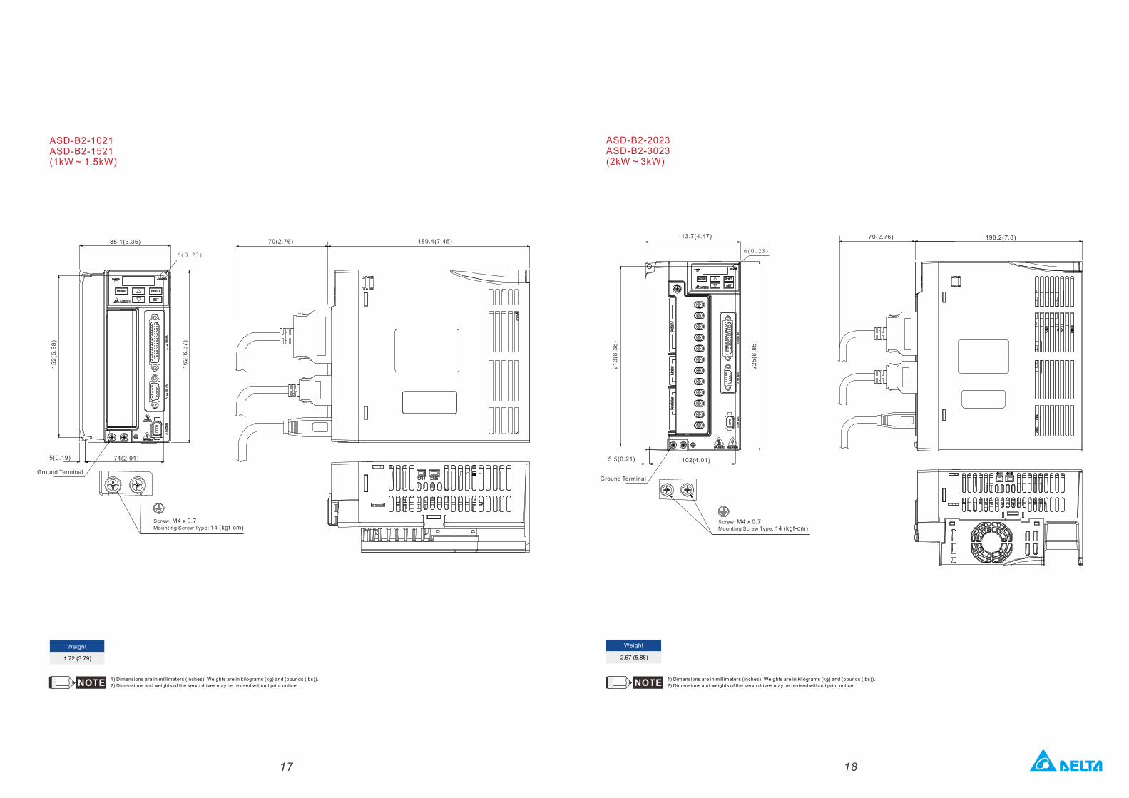
113.7(4.47) 70(2.76) 198.2(7.8)
102(4.01)5.5(0.21)
21
3(8
.38
)
22
5(8
.85
)
6(0.23)
17 18
ASD-B2-1021 ASD-B2-1521 (1kW ~ 1.5kW)
1.72 (3.79)
Weight
Screw: M4 x 0.7Mounting Screw Type: 14 (kgf-cm)
85.1(3.35)
5(0.19)
70(2.76) 189.4(7.45)
74(2.91)
15
2(5
.98
)
16
2(6
.37
)
6(0.23)
1) Dimensions are in millimeters (inches); Weights are in kilograms (kg) and (pounds (lbs)).
2) Dimensions and weights of the servo drives may be revised without prior notice.
ASD-B2-2023 ASD-B2-3023 (2kW ~ 3kW)
2.67 (5.88)
Weight
1) Dimensions are in millimeters (inches); Weights are in kilograms (kg) and (pounds (lbs)).
2) Dimensions and weights of the servo drives may be revised without prior notice.
Ground TerminalGround Terminal
19 20
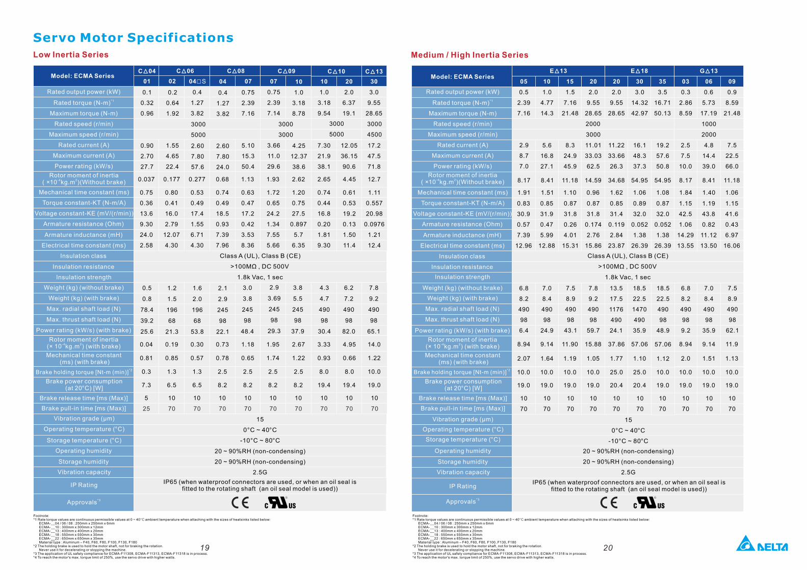
Medium / High Inertia SeriesLow Inertia Series
Servo Motor Specifications
Model: ECMA Series
Rated output power (kW)
*1Rated torque (N-m)
Maximum torque (N-m)
Rated speed (r/min)
Maximum speed (r/min)
Rated current (A)
Maximum current (A)
Power rating (kW/s)
Rotor moment of inertia-4 2( ×10 kg.m )(Without brake)
Mechanical time constant (ms)
Torque constant-KT (N-m/A)
Armature resistance (Ohm)
Armature inductance (mH)
Electrical time constant (ms)
Insulation class
Insulation resistance
Insulation strength
Weight (kg) (without brake)
Weight (kg) (with brake)
Max. radial shaft load (N)
Max. thrust shaft load (N)
Power rating (kW/s) (with brake)
Rotor moment of inertia-4 2(× 10 kg.m ) (with brake)
Mechanical time constant (ms) (with brake)
Brake power consumption (at 20 ) [W] °C
Brake release time [ms (Max)]
Brake pull-in time [ms (Max)]
Vibration grade (μm)
Operating temperature (°C)
Storage temperature (°C)
Operating humidity
Storage humidity
Vibration capacity
IP Rating
*3Approvals
Voltage constant-KE (mV/(r/min))
Model: ECMA Series
Rated output power (kW)
*1Rated torque (N-m)
Maximum torque (N-m)
Rated speed (r/min)
Maximum speed (r/min)
Rated current (A)
Maximum current (A)
Power rating (kW/s)
Rotor moment of inertia-4 2( ×10 kg.m )(Without brake)
Mechanical time constant (ms)
Torque constant-KT (N-m/A)
Armature resistance (Ohm)
Armature inductance (mH)
Electrical time constant (ms)
Insulation class
Insulation resistance
Insulation strength
Weight (kg) (without brake)
Weight (kg) (with brake)
Max. radial shaft load (N)
Max. thrust shaft load (N)
Power rating (kW/s) (with brake)
Voltage constant-KE (mV/(r/min))
Rotor moment of inertia-4 2(× 10 kg.m ) (with brake)
Mechanical time constant (ms) (with brake)
Brake power consumption (at 20 ) [W] °C
Brake release time [ms (Max)]
Brake pull-in time [ms (Max)]
Vibration grade (μm)
Operating temperature ( )°C
Storage temperature ( )°C
Operating humidity
Storage humidity
Vibration capacity
IP Rating
*3Approvals
3000
3000
3000
5000
E 13 ▲ E 18 ▲ G 13 ▲
05 10 15 20 20 30 03 06 09
0.5
2.39
7.16
1.0
4.77
14.3
1.5
7.16
21.48
2.0
9.55
28.65
3.0
14.32
42.97
2.0
9.55
28.65
0.3
2.86
8.59
0.6
5.73
17.19
0.9
8.59
21.48
2000 1000
2000 3000
2.9
8.7
7.0
5.6
16.8
27.1
8.3
24.9
45.9
11.01
33.03
62.5
11.22
33.66
26.3
16.1
48.3
37.3
2.5
7.5
10.0
4.8
14.4
39.0
7.5
22.5
66.0
6.8
8.2
490
98
6.4
7.0
8.4
490
98
24.9
7.5
8.9
490
98
43.1
7.8
9.2
490
98
59.7
13.5
17.5
1176
490
24.1
18.5
22.5
1470
490
35.9
6.8
8.2
490
98
9.2
7.0
8.4
490
98
35.9
7.5
8.9
490
98
62.1
C 04 ▲
01
0.1
0.32
0.96
0.90
2.70
27.7
0.5
0.8
78.4
39.2
25.6
02
0.2
0.64
1.92
1.55
4.65
22.4
1.2
1.5
196
68
21.3
04□S
0.4
1.27
3.82
1.6
2.0
196
68
53.8
2.60
7.80
57.6
04
0.4
1.27
3.82
3000
5000
2.1
2.9
245
98
22.1
2.60
7.80
24.0
07
0.75
2.39
7.16
3.0
3.8
245
98
48.4
5.10
15.3
50.4
07
0.75
2.39
7.14
2.9
3.69
245
98
29.3
3.66
11.0
29.6
10
1.0
3.18
8.78
4.25
12.37
38.6
C 10▲
10 20
1.0
3.18
9.54
2.0
6.37
19.1
3.8
5.5
245
98
37.9
6.2
7.2
490
98
82.0
7.30
21.9
38.1
12.05
36.15
90.6
C 06▲ C 08▲ C 09▲
Class A (UL), Class B (CE)
>100MΩ , DC 500V
1.8k Vac, 1 sec
IP65 (when waterproof connectors are used, or when an oil seal is fitted to the rotating shaft (an oil seal model is used))
4.3
4.7
490
98
30.4
30
3.0
9.55
28.65
7.8
9.2
490
98
65.1
17.2
47.5
71.8
C 13▲
3000
4500
35
3.5
16.71
50.13
19.2
57.6
50.8
18.5
22.5
490
98
48.9
15
0°C ~ 40 °C
-10°C ~ 80 °C
20 ~ 90%RH (non-condensing)
20 ~ 90%RH (non-condensing)
2.5G
25 70 70 70 70 70 70 70 70 70
5 10 10 10 10 10 10 10 10 10
7.3 6.5 6.5 8.2 8.2 8.2 8.2 19.4 19.4 19.0
0.04
0.81
0.3
0.19
0.85
1.3
0.30
0.57
1.3
0.73
0.78
2.5
1.18
0.65
2.5
1.95
1.74
2.5
2.67
1.22
2.5
3.33
0.93
8.0
4.95
0.66
8.0
14.0
1.22
10.0
0.75
0.36
13.6
9.30
24.0
2.58
0.80
0.41
16.0
2.79
12.07
4.30
0.53
0.49
17.4
1.55
6.71
4.30
0.74
0.49
18.5
0.93
7.39
7.96
0.63
0.47
17.2
0.42
3.53
8.36
1.72
0.65
24.2
1.34
7.55
5.66
1.20
0.75
27.5
0.897
5.7
6.35
0.74
0.44
16.8
0.20
1.81
9.30
0.61
0.53
19.2
0.13
1.50
11.4
1.11
0.557
20.98
0.0976
1.21
12.4
0.037 0.177 0.277 0.68 1.13 1.93 2.62 2.65 4.45 12.7
0.83
30.9
0.57
7.39
12.96
8.17
1.91
0.85
31.9
0.47
5.99
12.88
0.87
31.8
0.26
4.01
15.31
0.87
31.8
0.174
2.76
15.86
0.85
31.4
0.119
2.84
23.87
0.89
32.0
0.052
1.38
26.39
0.87
32.0
0.052
1.38
26.39
1.15
42.5
1.06
14.29
13.55
1.19
43.8
0.82
11.12
13.50
1.15
41.6
0.43
6.97
16.06
8.41
1.51
11.18
1.10
14.59
0.96
54.95
1.06
54.95
1.08
8.17
1.84
8.41
1.40
11.18
1.06
34.68
1.62
10
70
10
70
10
70
10
70
10
70
10
70
10
70
10
70
10
70
10
70
19.0 19.0 19.0 19.0 20.4 20.4 19.0 19.0 19.0 19.0
10.010.0 10.0 10.0 25.0 25.0 10.010.0 10.0 10.0
8.94
2.07
9.14
1.64
11.90
1.19
15.88
1.05
37.86
1.77
57.06
1.10
57.06
1.12
8.94
2.0
9.14
1.51
11.9
1.13
Class A (UL), Class B (CE)
>100MΩ , DC 500V
1.8k Vac, 1 sec
IP65 (when waterproof connectors are used, or when an oil seal is fitted to the rotating shaft (an oil seal model is used))
15
0°C ~ 40 °C
-10°C ~ 80 °C
20 ~ 90%RH (non-condensing)
20 ~ 90%RH (non-condensing)
2.5G
Footnote:*1 Rate torque values are continuous permissible values at 0 ~ 40 ambient temperature when attaching with the sizes of heatsinks listed below:°C ECMA-__04 / 06 / 08 : 250mm x 250mm x 6mm ECMA-__10 : 300mm x 300mm x 12mm ECMA-__13 : 400mm x 400mm x 20mm ECMA-__18 : 550mm x 550mm x 30mm ECMA-__22 : 650mm x 650mm x 35mm Material type : Aluminum – F40, F60, F80, F100, F130, F180*2 The holding brake is used to hold the motor shaft, not for braking the rotation. Never use it for decelerating or stopping the machine.*3 The application of UL safety compliance for ECMA-F11308, ECMA-F11313, ECMA-F11318 is in process.*4 To reach the motor's max. torque limit of 250%, use the servo drive with higher watts.
*2Brake holding torque [Nt-m (min)]
*2Brake holding torque [Nt-m (min)]
Footnote:*1 Rate torque values are continuous permissible values at 0 ~ 40 ambient temperature when attaching with the sizes of heatsinks listed below:°C ECMA-__04 / 06 / 08 : 250mm x 250mm x 6mm ECMA-__10 : 300mm x 300mm x 12mm ECMA-__13 : 400mm x 400mm x 20mm ECMA-__18 : 550mm x 550mm x 30mm ECMA-__22 : 650mm x 650mm x 35mm Material type : Aluminum – F40, F60, F80, F100, F130, F180*2 The holding brake is used to hold the motor shaft, not for braking the rotation. Never use it for decelerating or stopping the machine.*3 The application of UL safety compliance for ECMA-F11308, ECMA-F11313, ECMA-F11318 is in process.*4 To reach the motor's max. torque limit of 250%, use the servo drive with higher watts.
21 22
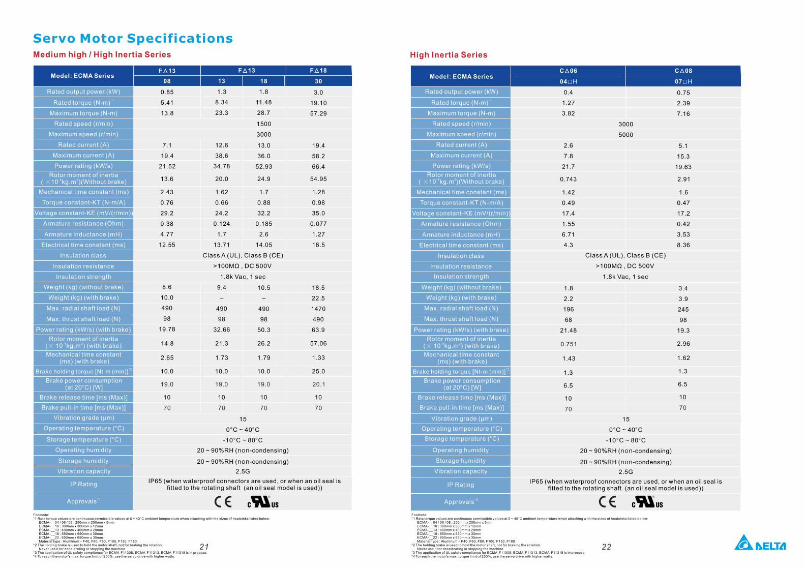
High Inertia SeriesMedium high / High Inertia Series
Servo Motor Specifications
Model: ECMA Series
Rated output power (kW)
*1Rated torque (N-m)
Maximum torque (N-m)
Rated speed (r/min)
Maximum speed (r/min)
Rated current (A)
Maximum current (A)
Power rating (kW/s)
Rotor moment of inertia-4 2( ×10 kg.m )(Without brake)
Mechanical time constant (ms)
Torque constant-KT (N-m/A)
Armature resistance (Ohm)
Armature inductance (mH)
Electrical time constant (ms)
Insulation class
Insulation resistance
Insulation strength
Weight (kg) (without brake)
Weight (kg) (with brake)
Max. radial shaft load (N)
Max. thrust shaft load (N)
Power rating (kW/s) (with brake)
Rotor moment of inertia-4 2(× 10 kg.m ) (with brake)
Mechanical time constant (ms) (with brake)
*2Brake holding torque [Nt-m (min)]
Brake power consumption (at 20 ) [W] °C
Brake release time [ms (Max)]
Brake pull-in time [ms (Max)]
Vibration grade (μm)
Operating temperature (°C)
Storage temperature (°C)
Operating humidity
Storage humidity
Vibration capacity
IP Rating
*3Approvals
Voltage constant-KE (mV/(r/min))
Model: ECMA Series
Rated output power (kW)
*1Rated torque (N-m)
Maximum torque (N-m)
Rated speed (r/min)
Maximum speed (r/min)
Rated current (A)
Maximum current (A)
Power rating (kW/s)
Rotor moment of inertia-4 2( ×10 kg.m )(Without brake)
Mechanical time constant (ms)
Torque constant-KT (N-m/A)
Armature resistance (Ohm)
Armature inductance (mH)
Electrical time constant (ms)
Insulation class
Insulation resistance
Insulation strength
Weight (kg) (without brake)
Weight (kg) (with brake)
Max. radial shaft load (N)
Max. thrust shaft load (N)
Power rating (kW/s) (with brake)
Voltage constant-KE (mV/(r/min))
Rotor moment of inertia-4 2(× 10 kg.m ) (with brake)
Mechanical time constant (ms) (with brake)
*2Brake holding torque [Nt-m (min)]
Brake power consumption (at 20 ) [W] °C
Brake release time [ms (Max)]
Brake pull-in time [ms (Max)]
Vibration grade (μm)
Operating temperature ( )°C
Storage temperature ( )°C
Operating humidity
Storage humidity
Vibration capacity
IP Rating
*3Approvals
IP65 (when waterproof connectors are used, or when an oil seal is fitted to the rotating shaft (an oil seal model is used))
15
0°C ~ 40 °C
-10°C ~ 80 °C
20 ~ 90%RH (non-condensing)
20 ~ 90%RH (non-condensing)
2.5G
F 13 ▲
08
0.85
5.41
13.8
7.1
19.4
21.52
8.6
10.0
490
98
19.78
13
1.3
8.34
23.3
12.6
38.6
34.78
9.4
–
490
98
32.66
18
1.8
11.48
28.7
10.5
–
490
98
50.3
13.0
36.0
52.93
30
3.0
19.10
57.29
1500
3000
18.5
22.5
1470
490
63.9
19.4
58.2
66.4
F 13▲ F 18▲
70 70 70 70
10 10 10 10
19.0 19.0 19.0 20.1
10.0 10.0 10.0 25.0
14.8
2.65
21.3
1.73
26.2
1.79
57.06
1.33
2.43
0.76
29.2
0.38
4.77
12.55
1.62
0.66
24.2
0.124
1.7
13.71
1.7
0.88
32.2
0.185
2.6
14.05
1.28
0.98
35.0
0.077
1.27
16.5
13.6 20.0 24.9 54.95
Class A (UL), Class B (CE)
>100MΩ , DC 500V
1.8k Vac, 1 sec
0.4
1.27
3.82
2.6
7.8
21.7
1.8
2.2
196
68
21.48
07□H
0.75
2.39
7.16
3.4
3.9
245
98
19.3
5.1
15.3
19.63
C 08▲
04□H
C 06▲
3000
5000
IP65 (when waterproof connectors are used, or when an oil seal is fitted to the rotating shaft (an oil seal model is used))
15
0°C ~ 40 °C
-10°C ~ 80 °C
20 ~ 90%RH (non-condensing)
20 ~ 90%RH (non-condensing)
2.5G
70 70
10 10
6.5 6.5
1.3 1.3
0.751
1.43
2.96
1.62
1.42
0.49
17.4
1.55
6.71
4.3
1.6
0.47
17.2
0.42
3.53
8.36
0.743 2.91
Class A (UL), Class B (CE)
>100MΩ , DC 500V
1.8k Vac, 1 sec
Footnote:*1 Rate torque values are continuous permissible values at 0 ~ 40 ambient temperature when attaching with the sizes of heatsinks listed below:°C ECMA-__04 / 06 / 08 : 250mm x 250mm x 6mm ECMA-__10 : 300mm x 300mm x 12mm ECMA-__13 : 400mm x 400mm x 20mm ECMA-__18 : 550mm x 550mm x 30mm ECMA-__22 : 650mm x 650mm x 35mm Material type : Aluminum – F40, F60, F80, F100, F130, F180*2 The holding brake is used to hold the motor shaft, not for braking the rotation. Never use it for decelerating or stopping the machine.*3 The application of UL safety compliance for ECMA-F11308, ECMA-F11313, ECMA-F11318 is in process.*4 To reach the motor's max. torque limit of 250%, use the servo drive with higher watts.
Footnote:*1 Rate torque values are continuous permissible values at 0 ~ 40 ambient temperature when attaching with the sizes of heatsinks listed below:°C ECMA-__04 / 06 / 08 : 250mm x 250mm x 6mm ECMA-__10 : 300mm x 300mm x 12mm ECMA-__13 : 400mm x 400mm x 20mm ECMA-__18 : 550mm x 550mm x 30mm ECMA-__22 : 650mm x 650mm x 35mm Material type : Aluminum – F40, F60, F80, F100, F130, F180*2 The holding brake is used to hold the motor shaft, not for braking the rotation. Never use it for decelerating or stopping the machine.*3 The application of UL safety compliance for ECMA-F11308, ECMA-F11313, ECMA-F11318 is in process.*4 To reach the motor's max. torque limit of 250%, use the servo drive with higher watts.
23 24
Speed-Torque Curves (T-N Curves)
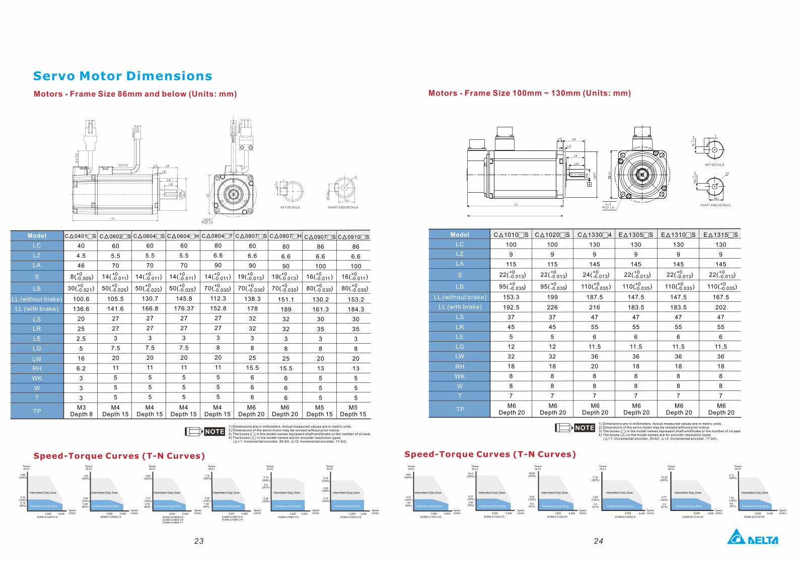
Motors - Frame Size 100mm ~ 130mm (Units: mm)Motors - Frame Size 86mm and below (Units: mm)
Servo Motor Dimensions
LG LR
LE
LS
LW
LB
h7
SHAFT END DETAILS
KEY DETAILS
Sh
6
4-LZPCD LA
W -
0.0
36
0
-0
.03
60
T
TP
RH
LC
LL
Speed-Torque Curves (T-N Curves)
Torque (N.m)
Speed (r/min)
Model
LC
LZ
LA
S
LB
LL (without brake)
LL (with brake)
LS
LR
LE
LG
LW
RH
WK
W
T
C 0401□S ▲
40
4.5
46
+0-0.009
100.6
136.6
20
25
2.5
5
16
6.2
3
3
3
M3Depth 8 TP
C 0602□S ▲
60
5.5
70
14( )
105.5
141.6
27
27
3
7.5
20
11
5
5
5
M4Depth 15
C 0604□S ▲
60
5.5
70
130.7
166.8
27
27
3
7.5
20
11
5
5
5
M4Depth 15
M4Depth 15
M6Depth 20
C 0804□7 ▲
80
6.6
90
112.3
152.8
27
27
3
8
20
11
5
5
5
C 0807□S ▲
80
6.6
90
138.3
178
32
32
3
8
25
15.5
6
6
6
C 0604□H ▲ C 0807□H ▲
60
5.5
70
145.8
176.37
27
27
3
7.5
20
11
5
5
5
M4Depth 15
1) Dimensions are in millimeters. Actual measured values are in metric units.2) Dimensions of the servo motor may be revised without prior notice.3) The boxes (c) in the model names represent shaft end/brake or the number of oil seal.4) The boxes ( ) in the model names are for encoder resolution types ▲ ( =1: Incremental encoder, 20-bit; =2: Incremental encoder, 17-bit).▲ ▲
������
+0-0.021������
8( )
30( )
+0-0.011������
+0-0.025������50( )
14( ) +0-0.011������
+0-0.025������50( )
14( ) +0-0.011
������
+0-0.030
������70( )
19( )+0-0.013������
+0-0.030
������70( )
M5Depth 15
86
6.6
100
130.2
161.3
30
35
3
8
20
13
5
5
5
16( )+0-0.011������
+0-0.030
������80( )
C 0907□S ▲
ECMA-C10602 S5,0003,000
ECMA-C10401 S
5,0003,000
0.38(60%)
1.92(300%)
0.64(100%)
0.96(300%)
0.32(100%)
0.19(60%)
3,0002,000
7.14(298%)
2.38(100%)
6.0(251%)
ECMA-C10907 S ECMA-C10910 S
8.78(276%)
3.18(100%)
3,0002,000
5.85(180%)
M5Depth 15
86
6.6
100
153.2
184.3
30
35
3
8
20
13
5
5
5
16( )+0-0.011������
+0-0.030
������80( )
C 0910□S ▲
14( ) +0-0.011������
+0-0.025������50( )
M6Depth 20
80
6.6
90
151.1
189
32
32
3
8
25
15.5
6
6
6
19( )+0-0.013������
+0-0.030
������70( )
ECMA-C10807 S
5,0003,000
7.16(300%)
2.39(100%)1.43
(60%)
ECMA-C10807 H
3.82(300%)
1.27(100%)0.76
(60%)
5,0003,000
ECMA-C10604 SECMA-C10604 HECMA-C10804 7
Intermittent Duty Zone
Continuous Duty Zone
Torque (N.m)
Speed (r/min)
Intermittent Duty Zone
Continuous Duty Zone
Torque (N.m)
Speed (r/min)
Intermittent Duty Zone
Continuous Duty Zone
Torque (N.m)
Speed (r/min)
Intermittent Duty Zone
Continuous Duty Zone
Torque (N.m)
Speed (r/min)
Intermittent Duty Zone
Continuous Duty Zone
Torque (N.m)
Speed (r/min)
Intermittent Duty Zone
Continuous Duty Zone
Model
LC
LZ
LA
S
LB
LS
LR
LE
LG
LW
RH
WK
W
T
TP
C 1010□S ▲
100
9
115
153.3
192.5
37
45
5
12
32
18
8
8
7
M6Depth 20
C 1020□S ▲
100
9
115
199
226
37
45
5
12
32
18
8
8
7
M6Depth 20
C 1330□4 ▲
130
9
145
187.5
216
47
55
6
11.5
36
20
8
8
7
M6Depth 20
E 1305□S ▲
130
9
145
147.5
183.5
47
55
6
11.5
36
18
8
8
7
M6Depth 20
E 1310□S ▲
130
9
145
147.5
183.5
47
55
6
11.5
36
18
8
8
7
M6Depth 20
E 1315□S ▲
130
9
145
167.5
202
47
55
6
11.5
36
18
8
8
7
M6Depth 20
22( )+0-0.013
������
+0-0.035
������95( )
19.11(300%)
6.37(100%)
3.82(60%)
5,0003,000
ECMA-C11020 S
28.65(300%)
9.55(100%)
6.4(67%)
2,0001,000
ECMA-C11330 4 ECMA-E11310 S
3,0002,000
ECMA-E11315 S
9.54(300%)
3.18(100%)
1.91(60%)
5,0003,000
ECMA-C11010 S
4.8(67%)
21.5(300%)
7.16(100%)
ECMA-E11305 S
3,0002,000
7.16(300%)
2.39(100%)
1.6(67%)
22( )+0-0.013
������
+0-0.035
������95( )
24( )+0-0.013
������
+0-0.035
������110( )
22( )+0-0.013
������
+0-0.035
������110( )
22( )+0-0.013
������
+0-0.035
������110( )
22( )+0-0.013
������
+0-0.035
������110( )
3,0002,000
14.32(300%)
4.77(100%)
3.2(67%)
Torque (N.m)
Speed (r/min)
Intermittent Duty Zone
Continuous Duty Zone
Torque (N.m)
Speed (r/min)
Intermittent Duty Zone
Continuous Duty Zone
Torque (N.m)
Speed (r/min)
Intermittent Duty Zone
Continuous Duty Zone
Torque (N.m)
Speed (r/min)
Intermittent Duty Zone
Continuous Duty Zone
Torque (N.m)
Speed (r/min)
Intermittent Duty Zone
Continuous Duty Zone
Torque (N.m)
Speed (r/min)
Intermittent Duty Zone
Continuous Duty Zone
1) Dimensions are in millimeters. Actual measured values are in metric units.2) Dimensions of the servo motor may be revised without prior notice.3) The boxes (c) in the model names represent shaft end/brake or the number of oil seal.4) The boxes ( ) in the model names are for encoder resolution types ▲ ( =1: Incremental encoder, 20-bit; =2: Incremental encoder, 17-bit).▲ ▲
LL (without brake)
LL (with brake)
LG LR
LE
LS
LWL
Bh
7
Sh
6
4-LZPCD LA
LC
SHAFT END DETAILSKEY DETAILS
LL
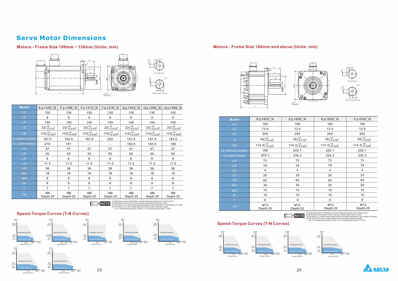
Servo Motor Dimensions
25 26
Motors - Frame Size 180mm and above (Units: mm)Motors - Frame Size 100mm ~ 130mm (Units: mm)
LG LR
LE
LS
LW
LB
h7
SHAFT END DETAILS
KEY DETAILS
Sh
6
4-LZPCD LA
W -
0.0
36
0
-0
.03
60
T
TP
RH
LC
LL
Speed-Torque Curves (T-N Curves)
Speed-Torque Curves (T-N Curves)
Model
LC
LZ
LA
S
LB
LS
LR
LE
LG
LW
RH
WK
W
T
TP
E 1820□S ▲
180
13.5
200
169
203.1
73
79
4
20
63
30
10
10
8
E 1830□S ▲
180
13.5
200
202.1
235.3
73
79
4
20
63
30
10
10
8
F 1830□S ▲
180
13.5
200
202.1
235.3
73
79
4
20
63
30
10
10
8
M12Depth 25
M12Depth 25
M12Depth 25
LR
Sh
6
LG
LE
LS
LW
Lb
h7
SHAFT END DETAILS
KEY DETAILS
T
LC
W
TP
RH
LL
4-LZPCD LA
35( )+0-0.016������+0-0.035������114.3( )
35( )+0-0.016������+0-0.035������114.3( )
35( )+0-0.016������+0-0.035������114.3( )
3,0002,000
ECMA-E11320 S
28.66(300%)
9.55(100%)
6.4(67%)
23.3(280%)
8.34(100%)
4.17(50%)
3,0001,500
ECMA-F11313 S
28.66(300%)
9.55(100%)
6.40(67%)
3,0002,000
ECMA-E11820 S
42.97(300%)
14.32(100%)
9.59(67%)
50.13(300%)
16.71(100%)
11.2(67%)
3,0002,000
ECMA-E11830 S
3,0002,000
ECMA-E11835 S
8.59(300%)
2.86(100%)
1.43(50%)
2,0001,000
ECMA-G11303 S
E 1835□S ▲
180
13.5
200
202.1
235.3
73
79
4
20
63
30
10
10
8
M12Depth 25
35( )+0-0.016������+0-0.035������114.3( )
57.29(300%)
19.1(100%)
9.55(67%)
3,0001,500
ECMA-F11830 S
Model
LC
LZ
LA
S
LB
LS
LR
LE
LG
LW
RH
WK
W
T
TP
F 1308□S ▲
130
9
145
152.5
181
47
55
6
11.5
36
18
8
8
7
M6Depth 20
22( )+0-0.013������+0-0.035������110( )
F 1313□S ▲
130
9
145
187.5
- -
47
55
6
11.5
36
18
8
8
7
M6Depth 20
22( )+0-0.013������+0-0.035������110( )
F 1318□S ▲
130
9
145
202
- -
47
55
6
11.5
36
18
8
8
7
M6Depth 20
22( )+0-0.013������+0-0.035������110( )
G 1303□S ▲
130
9
145
147.5
183.5
47
55
6
11.5
36
18
8
8
7
M6Depth 20
22( )+0-0.013������+0-0.035������110( )
E 1320□S ▲
130
9
145
187.5
216
47
55
6
11.5
36
18
8
8
7
M6Depth 20
22( )+0-0.013������+0-0.035������110( )
G 1306□S ▲
130
9
145
147.5
183.5
47
55
6
11.5
36
18
8
8
7
M6Depth 20
22( )+0-0.013������+0-0.035������110( )
G 1309□S ▲
130
9
145
163.5
198
47
55
6
11.5
36
18
8
8
7
M6Depth 20
22( )+0-0.013������+0-0.035������110( )
3,0001,500
ECMA-F11308 S
13.80(255%)
7(130%)5.41(100%)
2.70(50%)
2,000
28.7(250%)
11.48(100%)
5.74(50%)
3,0001,500
ECMA-F11318 S
2,000
17.19(300%)
5.73(100%)
2.87(50%)
2,0001,000
ECMA-G11306 S
21.48(250%)
8.59(100%)
4.29(50%)
2,0001,000
ECMA-G11309 S
LL (without brake)
LL (with brake)
Torque (N.m)
Speed (r/min)
Intermittent Duty Zone
Continuous Duty Zone
Torque (N.m)
Speed (r/min)
Intermittent Duty Zone
Continuous Duty Zone
Torque (N.m)
Speed (r/min)
Intermittent Duty Zone
Continuous Duty Zone
Torque (N.m)
Speed (r/min)
Intermittent Duty Zone
Continuous Duty Zone
Torque (N.m)
Speed (r/min)
Intermittent Duty Zone
Continuous Duty Zone
Torque (N.m)
Speed (r/min)
Intermittent Duty Zone
Continuous Duty Zone
Torque (N.m)
Speed (r/min)
Intermittent Duty Zone
Continuous Duty Zone
LL (without brake)
LL (with brake)
Torque (N.m)
Speed (r/min)
Intermittent Duty Zone
Continuous Duty Zone
Torque (N.m)
Speed (r/min)
Intermittent Duty Zone
Continuous Duty Zone
Torque (N.m)
Speed (r/min)
Intermittent Duty Zone
Continuous Duty Zone
Torque (N.m)
Speed (r/min)
Intermittent Duty Zone
Continuous Duty Zone
1) Dimensions are in millimeters. Actual measured values are in metric units.2) Dimensions of the servo motor may be revised without prior notice.3) The boxes (c) in the model names represent shaft end/brake or the number of oil seal.4) The boxes ( ) in the model names are for encoder resolution types ▲ ( =1: Incremental encoder, 20-bit; =2: Incremental encoder, 17-bit).▲ ▲
1) Dimensions are in millimeters. Actual measured values are in metric units.2) Dimensions of the servo motor may be revised without prior notice.3) The boxes (c) in the model names represent shaft end/brake or the number of oil seal.4) The boxes ( ) in the model names are for encoder resolution types ▲ ( =1: Incremental encoder, 20-bit; =2: Incremental encoder, 17-bit).▲ ▲
27 28
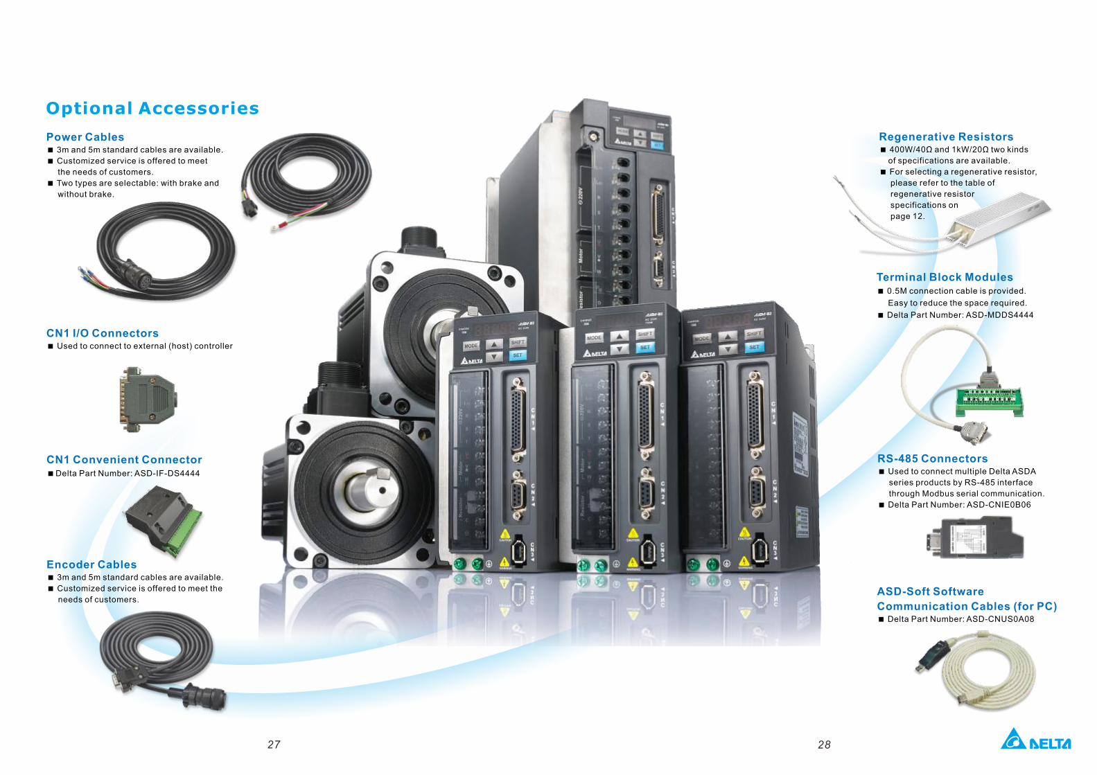
Terminal Block Modules< 0.5M connection cable is provided.
Easy to reduce the space required.
< Delta Part Number: ASD-MDDS4444
CN1 Convenient Connector<Delta Part Number: ASD-IF-DS4444
Optional Accessories
Power Cables< 3m and 5m standard cables are available.
< Customized service is offered to meet
the needs of customers.
< Two types are selectable: with brake and
without brake.
Encoder Cables< 3m and 5m standard cables are available.
< Customized service is offered to meet the
needs of customers.
CN1 I/O Connectors< Used to connect to external (host) controller
Regenerative Resistors< 400W/40Ω and 1kW/20Ω two kinds
of specifications are available.
< For selecting a regenerative resistor,
please refer to the table of
regenerative resistor
specifications on
page 12.
RS-485 Connectors< Used to connect multiple Delta ASDA
series products by RS-485 interface
through Modbus serial communication.
< Delta Part Number: ASD-CNIE0B06
ASD-Soft Software
Communication Cables (for PC)< Delta Part Number: ASD-CNUS0A08
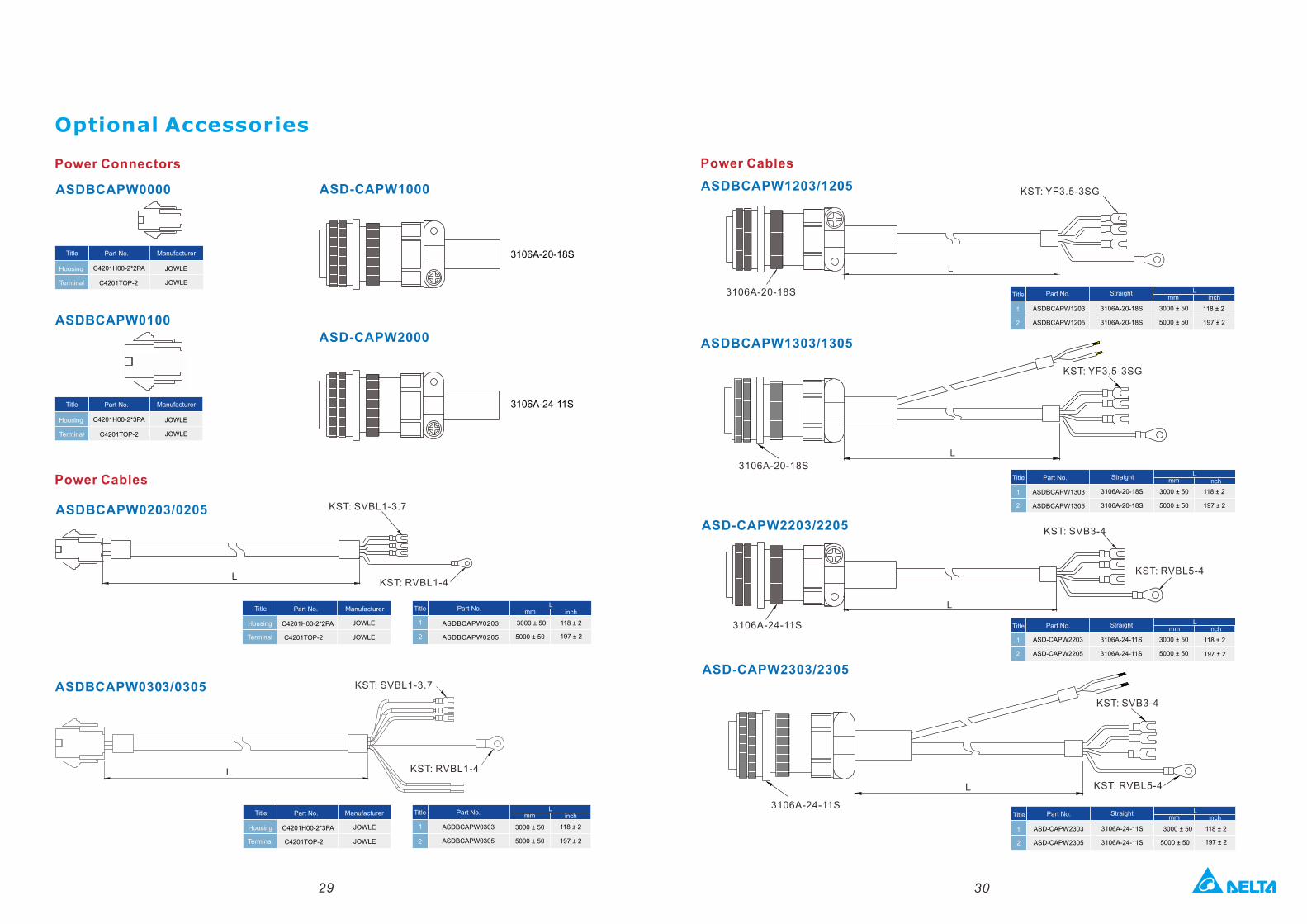
ASDBCAPW0000 ASD-CAPW1000
Housing
Terminal
Title
C4201H00-2*2PA
C4201TOP-2
Manufacturer
JOWLE
JOWLE
3106A-20-18S
3106A-24-11S
ASD-CAPW2000
ASDBCAPW0100
Housing
Terminal
Title
C4201H00-2*3PA
C4201TOP-2
Manufacturer
JOWLE
JOWLE
ASDBCAPW0203/0205
Title Manufacturer
Housing C4201H00-2*2PA JOWLE
Terminal C4201TOP-2 JOWLE
TitleL
mm inch
1 ASDBCAPW0203 3000 ± 50 118 ± 2
2 ASDBCAPW0205 5000 ± 50 197 ± 2
ASDBCAPW0303/0305
Title Manufacturer
Housing C4201H00-2*3PA JOWLE
Terminal C4201TOP-2 JOWLE
TitleL
mm inch
1 ASDBCAPW0303 3000 ± 50 118 ± 2
2 ASDBCAPW0305 5000 ± 50 197 ± 2
KST: SVBL1-3.7
KST: RVBL1-4L
KST: SVBL1-3.7
KST: RVBL1-4L
29
ASDBCAPW1303/1305
ASD-CAPW2203/2205
Title Straight Lmm inch
1 ASD-CAPW2203 3106A-24-11S
2 ASD-CAPW2205 3106A-24-11S
Title Straight L
mm inch
1 ASDBCAPW1303 3106A-20-18S 3000 ± 50 118 ± 2
2 ASDBCAPW1305 3106A-20-18S 5000 ± 50 197 ± 2
ASDBCAPW1203/1205
Title Straight Lmm inch
1 ASDBCAPW1203 3106A-20-18S 3000 ± 50 118 ± 2
2 ASDBCAPW1205 3106A-20-18S 5000 ± 50 197 ± 2
3106A-20-18S
KST: YF3.5-3SG
L
3106A-20-18S
KST: YF3.5-3SG
L
3106A-24-11S
KST: SVB3-4
L
KST: RVBL5-4
3000 ± 50 118 ± 2
5000 ± 50 197 ± 2
30
ASD-CAPW2303/2305
3106A-24-11S
KST: SVB3-4
KST: RVBL5-4L
Title Straight Lmm inch
1 ASD-CAPW2303 3106A-24-11S
2 ASD-CAPW2305 3106A-24-11S
3000 ± 50 118 ± 2
5000 ± 50 197 ± 2
Optional Accessories
Power Connectors
Power Cables
Power Cables
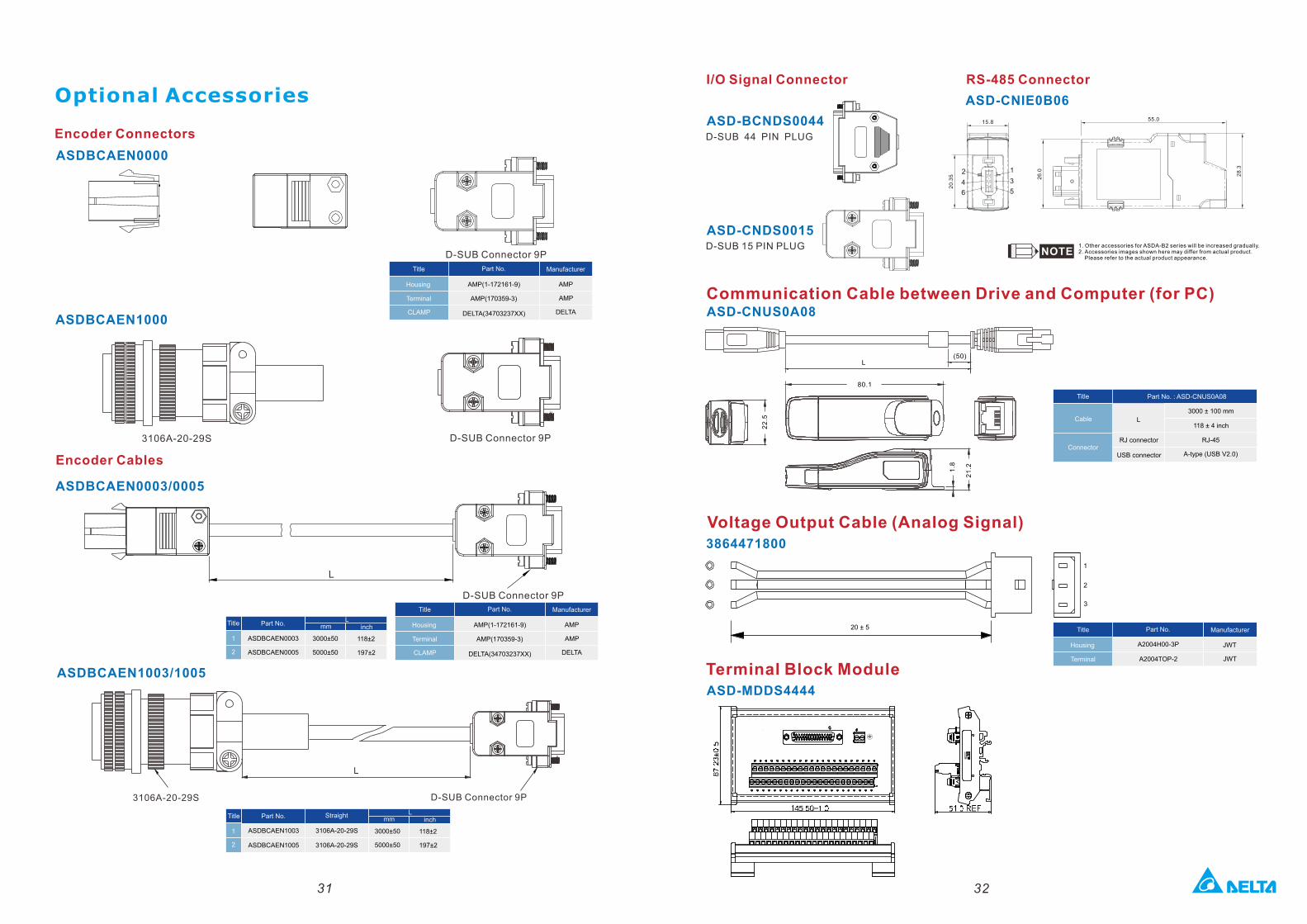
ASDBCAEN0000
Housing
Terminal
Title
AMP(1-172161-9)
Manufacturer
AMP
AMP
ASDBCAEN1000
AMP(170359-3)
DELTADELTA(34703237XX)CLAMP
D-SUB Connector 9P
3106A-20-29S D-SUB Connector 9P
ASDBCAEN0003/0005
D-SUB Connector 9P
L
LTitle
inchmm
1 ASDBCAEN0003
2 ASDBCAEN0005
Housing
Terminal
Title
AMP(1-172161-9)
Manufacturer
AMP
AMPAMP(170359-3)
DELTADELTA(34703237XX)CLAMP
ASDBCAEN1003/1005
D-SUB Connector 9P
L
3106A-20-29S
31
Optional Accessories
Encoder Cables
Encoder Connectors
32
3000±50
5000±50
118±2
197±2
LTitle
inchmm
1 ASDBCAEN1003
2 ASDBCAEN1005
3000±50 118±2
5000±50 197±2
3106A-20-29S
3106A-20-29S
Straight
ASD-BCNDS0044D-SUB 44 PIN PLUG
ASD-CNDS0015
ASD-CNUS0A08
Cable
Title
L
Part No. : ASD-CNUS0A08
3000 ± 100 mm
118 ± 4 inch
RJ-45
A-type (USB V2.0)Connector
RJ connector
USB connector
L(50)
80.1
21
.21.8
22
.5
1
2
3
20 ± 5
Housing
Terminal
Title
A2004H00-3P
Manufacturer
JWT
JWTA2004TOP-2
D-SUB 15 PIN PLUG
Terminal Block ModuleASD-MDDS4444
I/O Signal Connector RS-485 Connector
ASD-CNIE0B06
1. Other accessories for ASDA-B2 series will be increased gradually.2. Accessories images shown here may differ from actual product. Please refer to the actual product appearance.
Communication Cable between Drive and Computer (for PC)
Voltage Output Cable (Analog Signal)3864471800
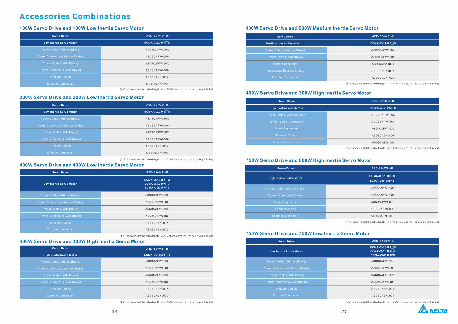
100W Servo Drive and 100W Low Inertia Servo Motor
200W Servo Drive and 200W Low Inertia Servo Motor
400W Servo Drive and 400W Low Inertia Servo Motor
(X=3 indicates that the cable length is 3m; X=5 indicates that the cable length is 5m)
400W Servo Drive and 500W Medium Inertia Servo Motor
400W Servo Drive and 300W High Inertia Servo Motor
750W Servo Drive and 750W Low Inertia Servo Motor
(X=3 indicates that the cable length is 3m; X=5 indicates that the cable length is 5m)
(X=3 indicates that the cable length is 3m; X=5 indicates that the cable length is 5m)
400W Servo Drive and 400W High Inertia Servo Motor
(X=3 indicates that the cable length is 3m; X=5 indicates that the cable length is 5m)
750W Servo Drive and 600W High Inertia Servo Motor
(X=3 indicates that the cable length is 3m; X=5 indicates that the cable length is 5m)
(X=3 indicates that the cable length is 3m; X=5 indicates that the cable length is 5m)
(X=3 indicates that the cable length is 3m; X=5 indicates that the cable length is 5m)
(X=3 indicates that the cable length is 3m; X=5 indicates that the cable length is 5m)
Accessories Combinations
ASD-B2-0421-B
ASDBCAPW020X
ASDBCAPW0000
ASDBCAPW030X
ASDBCAPW0100
ASDBCAEN000X
ASDBCAEN0000
ECMA-C 0604 H▲ □
33 34
ASD-B2-0121-B
ECMA-C 0401 S▲ □
ASDBCAPW020X
ASDBCAPW0000
ASDBCAPW030X
ASDBCAPW0100
ASDBCAEN000X
ASDBCAEN0000
ASD-B2-0221-B
ECMA-C 0602 S▲ □
ASDBCAPW020X
ASDBCAPW0000
ASDBCAPW030X
ASDBCAPW0100
ASDBCAEN000X
ASDBCAEN0000
ECMA-C 0604 S▲ □
ECMA-C 0804 7▲ □
ECMA-CM0604PS
ASD-B2-0421-B
ASDBCAPW020X
ASDBCAPW0000
ASDBCAPW030X
ASDBCAPW0100
ASDBCAEN000X
ASDBCAEN0000
ASD-B2-0421-B
ECMA-E 1305 S▲ □
ASDBCAPW120X
ASDBCAPW130X
ASD-CAPW1000
ASDBCAEN100X
ASDBCAEN1000
ASD-B2-0421-B
ECMA-G 1303 S▲ □
ASDBCAPW120X
ASDBCAPW130X
ASD-CAPW1000
ASDBCAEN100X
ASDBCAEN1000
ECMA-G 1306 S▲ □
ECMA-GM1306PS
ASD-B2-0721-B
ASDBCAPW120X
ASDBCAPW130X
ASD-CAPW1000
ASDBCAEN100X
ASDBCAEN1000
ECMA-C 0807 S▲ □
ECMA-C 0907 7▲ □
ECMA-CM0807PS
ASD-B2-0721-B
ASDBCAPW020X
ASDBCAPW0000
ASDBCAPW030X
ASDBCAPW0100
ASDBCAEN000X
ASDBCAEN0000
Servo Drive
Low Inertia Servo Motor
Power Cables (Without Brake)
Power Connectors (Without Brake)
Power Cables (With Brake)
Power Connectors (With Brake)
Encoder Cables
Encoder Connectors
Servo Drive
Low Inertia Servo Motor
Power Cables (Without Brake)
Power Connectors (Without Brake)
Power Cables (With Brake)
Power Connectors (With Brake)
Encoder Cables
Encoder Connectors
Servo Drive
Power Cables (Without Brake)
Power Connectors (Without Brake)
Power Cables (With Brake)
Power Connectors (With Brake)
Encoder Cables
Encoder Connectors
Low Inertia Servo Motor
Servo Drive
High Inertia Servo Motor
Power Cables (Without Brake)
Power Connectors (Without Brake)
Power Cables (With Brake)
Power Connectors (With Brake)
Encoder Cables
Encoder Connectors
Servo Drive
Medium Inertia Servo Motor
Power Cables (Without Brake)
Power Cables (With Brake)
Power Connectors
Incremental Encoder Cables
Encoder Connectors
Servo Drive
Power Cables (Without Brake)
Power Cables (With Brake)
Power Connectors
Encoder Cables
Encoder Connectors
High Inertia Servo Motor
Servo Drive
High Inertia Servo Motor
Power Cables (Without Brake)
Power Cables (With Brake)
Power Connectors
Encoder Cables
Encoder Connectors
Servo Drive
Power Cables (Without Brake)
Power Connectors (Without Brake)
Power Cables (With Brake)
Power Connectors (With Brake)
Encoder Cables
Encoder Connectors
Low Inertia Servo Motor
Accessories Combinations
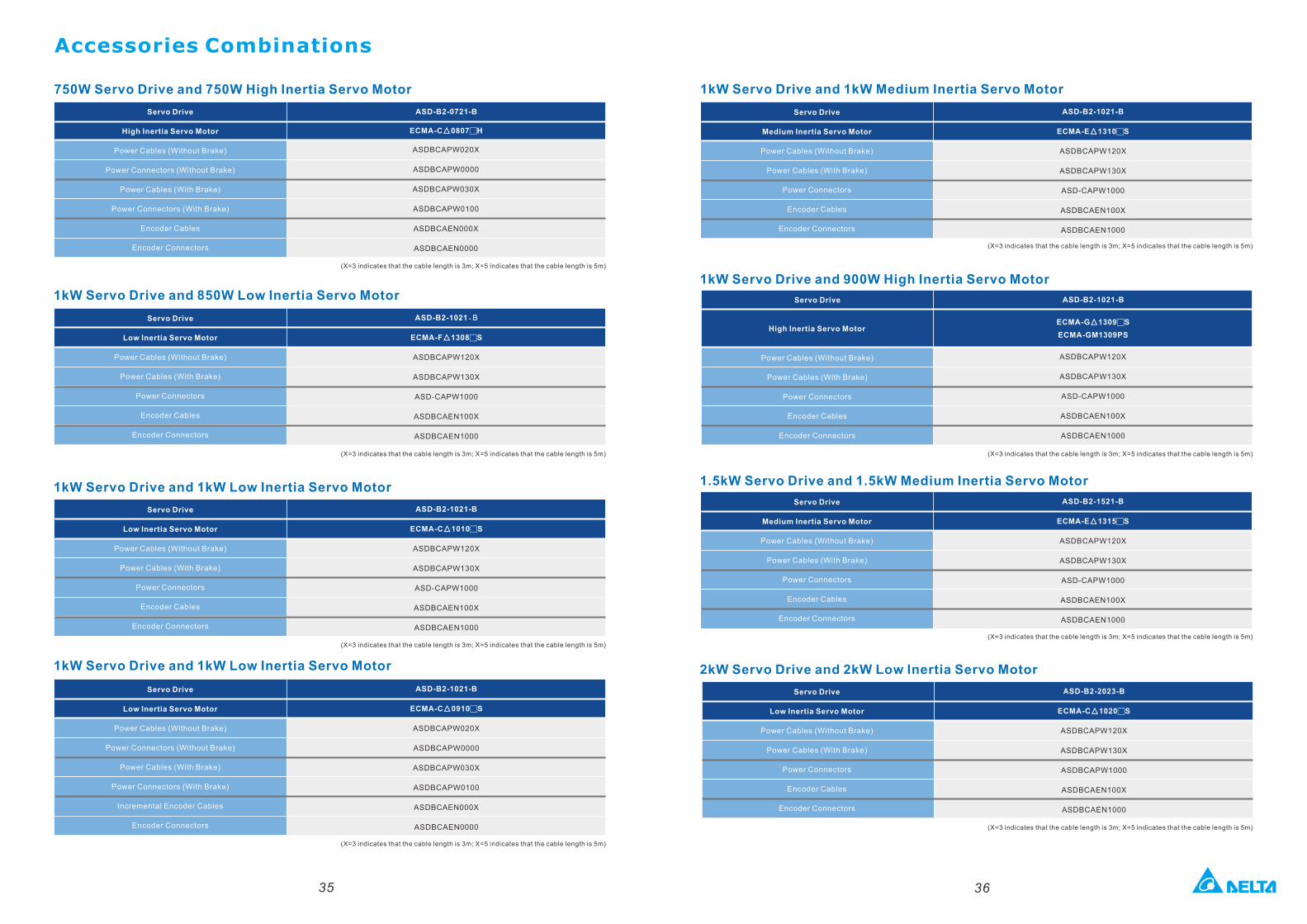
750W Servo Drive and 750W High Inertia Servo Motor
1kW Servo Drive and 850W Low Inertia Servo Motor
1kW Servo Drive and 1kW Low Inertia Servo Motor
1kW Servo Drive and 1kW Low Inertia Servo Motor 2kW Servo Drive and 2kW Low Inertia Servo Motor
35 36
ASD-B2-1021-B
ECMA-C 1010 S▲ □
ASDBCAPW120X
ASDBCAPW130X
ASD-CAPW1000
ASDBCAEN100X
ASDBCAEN1000
ASD-B2-1021-B
ECMA-E 1310 S▲ □
ASDBCAPW120X
ASDBCAPW130X
ASD-CAPW1000
ASDBCAEN100X
ASDBCAEN1000
ECMA-G 1309 S▲ □
ECMA-GM1309PS
ASD-B2-1021-B
ASDBCAPW120X
ASDBCAPW130X
ASD-CAPW1000
ASDBCAEN100X
ASDBCAEN1000
ASD-B2-1521-B
ECMA-E 1315 S▲ □
ASDBCAPW120X
ASDBCAPW130X
ASD-CAPW1000
ASDBCAEN100X
ASDBCAEN1000
ECMA-C 0807▲ □H
ASD-B2-0721-B
ASDBCAPW020X
ASDBCAPW0000
ASDBCAPW030X
ASDBCAPW0100
ASDBCAEN000X
ASDBCAEN0000
ASD-B2-1021-B
ECMA-F 1308 S▲ □
ASDBCAPW120X
ASDBCAPW130X
ASD-CAPW1000
ASDBCAEN100X
ASDBCAEN1000
ASD-B2-1021-B
ECMA-C 0910 S▲ □
ASDBCAPW020X
ASDBCAPW0000
ASDBCAPW030X
ASDBCAPW0100
ASDBCAEN000X
ASDBCAEN0000
ASD-B2-2023-B
ECMA-C 1020 S▲ □
ASDBCAPW120X
ASDBCAPW130X
ASDBCAPW1000
ASDBCAEN100X
ASDBCAEN1000
Servo Drive
Low Inertia Servo Motor
Power Cables (Without Brake)
Power Connectors (Without Brake)
Power Cables (With Brake)
Power Connectors (With Brake)
Incremental Encoder Cables
Encoder Connectors
Servo Drive
High Inertia Servo Motor
Power Cables (Without Brake)
Power Connectors (Without Brake)
Power Cables (With Brake)
Power Connectors (With Brake)
Encoder Cables
Encoder Connectors
Servo Drive
Low Inertia Servo Motor
Power Cables (Without Brake)
Power Cables (With Brake)
Power Connectors
Encoder Cables
Encoder Connectors
Servo Drive
Low Inertia Servo Motor
Power Cables (Without Brake)
Power Cables (With Brake)
Power Connectors
Encoder Cables
Encoder Connectors
(X=3 indicates that the cable length is 3m; X=5 indicates that the cable length is 5m)
(X=3 indicates that the cable length is 3m; X=5 indicates that the cable length is 5m)
(X=3 indicates that the cable length is 3m; X=5 indicates that the cable length is 5m)
(X=3 indicates that the cable length is 3m; X=5 indicates that the cable length is 5m)
1kW Servo Drive and 1kW Medium Inertia Servo Motor
1kW Servo Drive and 900W High Inertia Servo Motor
1.5kW Servo Drive and 1.5kW Medium Inertia Servo Motor
(X=3 indicates that the cable length is 3m; X=5 indicates that the cable length is 5m)
(X=3 indicates that the cable length is 3m; X=5 indicates that the cable length is 5m)
(X=3 indicates that the cable length is 3m; X=5 indicates that the cable length is 5m)
(X=3 indicates that the cable length is 3m; X=5 indicates that the cable length is 5m)
Servo Drive
Medium Inertia Servo Motor
Power Cables (Without Brake)
Power Cables (With Brake)
Power Connectors
Encoder Cables
Encoder Connectors
Servo Drive
Medium Inertia Servo Motor
Power Cables (Without Brake)
Power Cables (With Brake)
Power Connectors
Encoder Cables
Encoder Connectors
Servo Drive
Low Inertia Servo Motor
Power Cables (Without Brake)
Power Cables (With Brake)
Power Connectors
Encoder Cables
Encoder Connectors
Servo Drive
Power Cables (Without Brake)
Power Cables (With Brake)
Power Connectors
Encoder Cables
Encoder Connectors
High Inertia Servo Motor
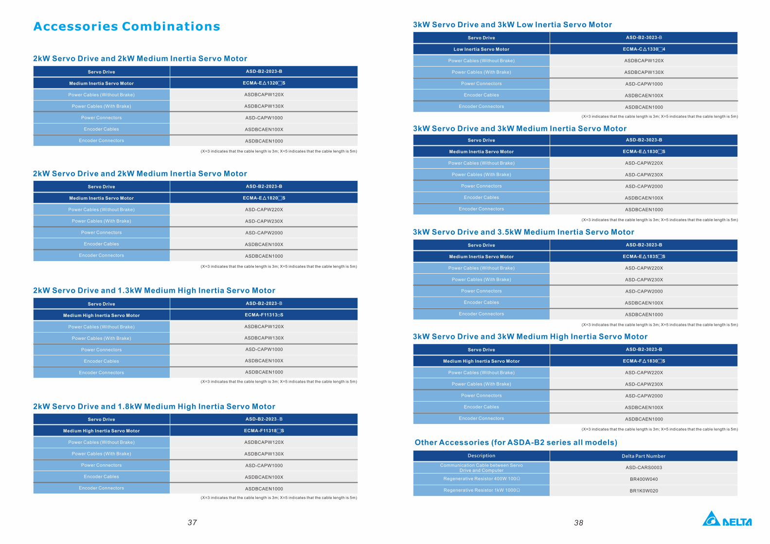
Accessories Combinations
2kW Servo Drive and 2kW Medium Inertia Servo Motor
2kW Servo Drive and 2kW Medium Inertia Servo Motor
2kW Servo Drive and 1.3kW Medium High Inertia Servo Motor
2kW Servo Drive and 1.8kW Medium High Inertia Servo Motor
37
ASD-B2-2023-B
ECMA-E 1320 S▲ □
ASDBCAPW120X
ASDBCAPW130X
ASD-CAPW1000
ASDBCAEN100X
ASDBCAEN1000
ASD-B2-2023-B
ECMA-E 1820 S▲ □
ASD-CAPW220X
ASD-CAPW230X
ASD-CAPW2000
ASDBCAEN100X
ASDBCAEN1000
38
ASD-B2-3023-B
ECMA-E 1830 S▲ □
ASD-CAPW220X
ASD-CAPW230X
ASD-CAPW2000
ASDBCAEN100X
ASDBCAEN1000
ASD-B2-3023-B
ECMA-F 1830 S▲ □
ASD-CAPW220X
ASD-CAPW230X
ASD-CAPW2000
ASDBCAEN100X
ASDBCAEN1000
ASD-B2-3023-B
ECMA-E 1835 S▲ □
ASD-CAPW220X
ASD-CAPW230X
ASD-CAPW2000
ASDBCAEN100X
ASDBCAEN1000
ASD-B2-3023-B
ECMA-C 1330 4▲ □
ASDBCAPW120X
ASDBCAPW130X
ASD-CAPW1000
ASDBCAEN100X
ASDBCAEN1000
ASD-B2-2023 B-
ECMA-F11313 S□
Other Accessories (for ASDA-B2 series all models)
Description
ASD-CARS0003
BR400W040
BR1K0W020
Delta Part Number
ASDBCAPW120X
ASDBCAPW130X
ASD-CAPW1000
ASDBCAEN100X
ASDBCAEN1000
ASD-B2-2023-B
ECMA-F11318 S□
ASDBCAPW120X
ASDBCAPW130X
ASD-CAPW1000
ASDBCAEN100X
ASDBCAEN1000
Servo Drive
Medium Inertia Servo Motor
Power Cables (Without Brake)
Power Cables (With Brake)
Power Connectors
Encoder Cables
Encoder Connectors
Servo Drive
Medium Inertia Servo Motor
Power Cables (Without Brake)
Power Cables (With Brake)
Power Connectors
Encoder Cables
Encoder Connectors
Servo Drive
Medium High Inertia Servo Motor
Power Cables (Without Brake)
Power Cables (With Brake)
Power Connectors
Encoder Cables
Encoder Connectors
Servo Drive
Medium High Inertia Servo Motor
Power Cables (Without Brake)
Power Cables (With Brake)
Power Connectors
Encoder Cables
Encoder Connectors
(X=3 indicates that the cable length is 3m; X=5 indicates that the cable length is 5m)
(X=3 indicates that the cable length is 3m; X=5 indicates that the cable length is 5m)
(X=3 indicates that the cable length is 3m; X=5 indicates that the cable length is 5m)
(X=3 indicates that the cable length is 3m; X=5 indicates that the cable length is 5m)
3kW Servo Drive and 3kW Low Inertia Servo Motor
3kW Servo Drive and 3kW Medium Inertia Servo Motor
3kW Servo Drive and 3.5kW Medium Inertia Servo Motor
3kW Servo Drive and 3kW Medium High Inertia Servo Motor
Servo Drive
Low Inertia Servo Motor
Power Cables (Without Brake)
Power Cables (With Brake)
Power Connectors
Encoder Cables
Encoder Connectors
Servo Drive
Medium Inertia Servo Motor
Power Cables (Without Brake)
Power Cables (With Brake)
Power Connectors
Encoder Cables
Encoder Connectors
Servo Drive
Medium Inertia Servo Motor
Power Cables (Without Brake)
Power Cables (With Brake)
Power Connectors
Encoder Cables
Encoder Connectors
Servo Drive
Medium High Inertia Servo Motor
Power Cables (Without Brake)
Power Cables (With Brake)
Power Connectors
Encoder Cables
Encoder Connectors
(X=3 indicates that the cable length is 3m; X=5 indicates that the cable length is 5m)
(X=3 indicates that the cable length is 3m; X=5 indicates that the cable length is 5m)
(X=3 indicates that the cable length is 3m; X=5 indicates that the cable length is 5m)
(X=3 indicates that the cable length is 3m; X=5 indicates that the cable length is 5m)
Communication Cable between ServoDrive and Computer
Regenerative Resistor 400W 100Ω
Regenerative Resistor 1kW 1000Ω