Embed Size (px)
Citation preview
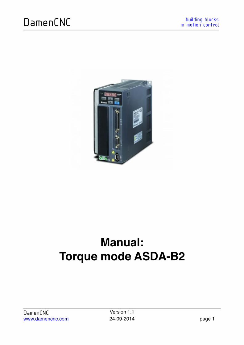
Manual:Torque mode ASDA-B2
DamenCNC building blocksDamenCNC in motion control
DamenCNC Version 1.1www.damencnc.com 24-09-2014 page 1
DamenCNC B.V. the NetherlandsLouis Pasteurweg 15-17
2408 AH Alphen aan den Rijn
Author:Harm van Scheppingen
Revision historyRevision historyRevision history
-
DamenCNC building blocksDamenCNC in motion control
DamenCNC Version 1.1www.damencnc.com 24-09-2014 page 2
PrefaceThank you for choosing the
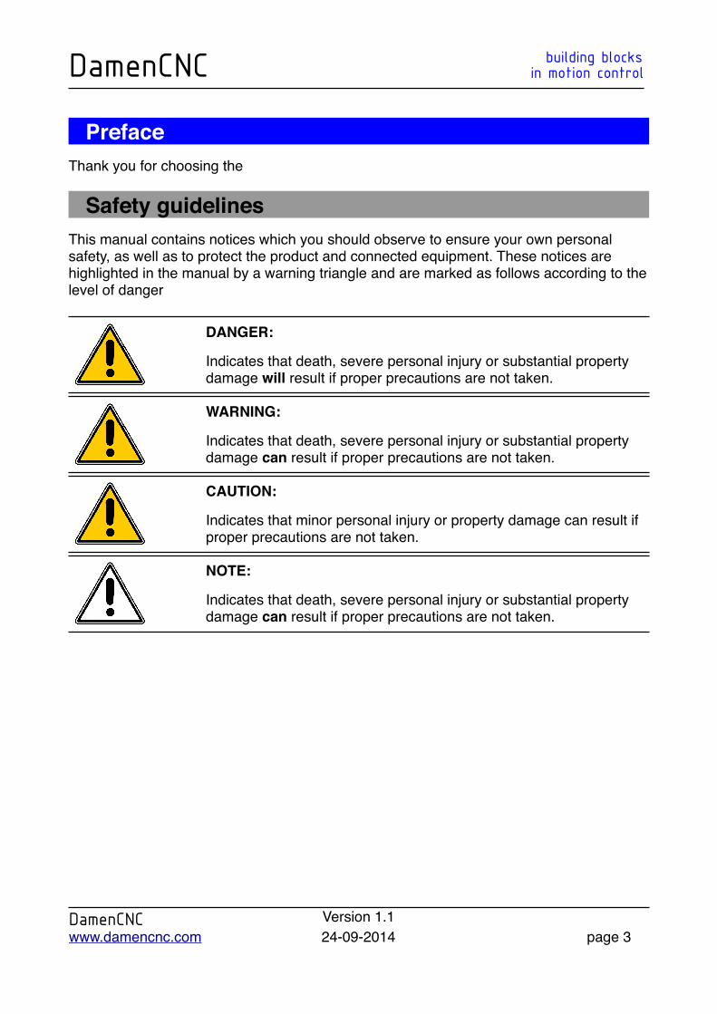
Safety guidelinesThis manual contains notices which you should observe to ensure your own personal safety, as well as to protect the product and connected equipment. These notices are highlighted in the manual by a warning triangle and are marked as follows according to the level of danger
DANGER:
Indicates that death, severe personal injury or substantial property damage will result if proper precautions are not taken.
WARNING:
Indicates that death, severe personal injury or substantial property damage can result if proper precautions are not taken.
CAUTION:
Indicates that minor personal injury or property damage can result if proper precautions are not taken.
NOTE:
Indicates that death, severe personal injury or substantial property damage can result if proper precautions are not taken.
DamenCNC building blocksDamenCNC in motion control
DamenCNC Version 1.1www.damencnc.com 24-09-2014 page 3
Content Page
1. Introduction! 6
2. Powering the drive ! 7
2.1 Drive powering check! 8
3 Wiring the motor and encoder to the drive! 8
3.1 Wiring the motor to the drive ! 8
3.2 Wiring the motor brake ! 9
3.3 Wiring the encoder! 10
3.4 Wiring the control cable ! 11
3.5 Drive powering check! 12
4. Parameter settings ! 13
4.1 P2-15, P2-16 & P2-17 input! 15
4.2 P1-44 Electronic gear ratio! 16
4.3 P1-01 control mode! 17
4.4 P1-12 Torque command! 18
4.5 P1-13 Torque command! 19
4.6 P1-14 Torque command! 20
4.7 P2-10 Digital input terminal! 21
4.8 P2-12 Digital input terminal! 22
4.9 P1-55 Digital input terminal! 23
4.10 P1-07 Digital input terminal! 24
DamenCNC building blocksDamenCNC in motion control
DamenCNC Version 1.1www.damencnc.com 24-09-2014 page 4
4.11 Saving the altered parameters ! 25
DamenCNC building blocksDamenCNC in motion control
DamenCNC Version 1.1www.damencnc.com 24-09-2014 page 5
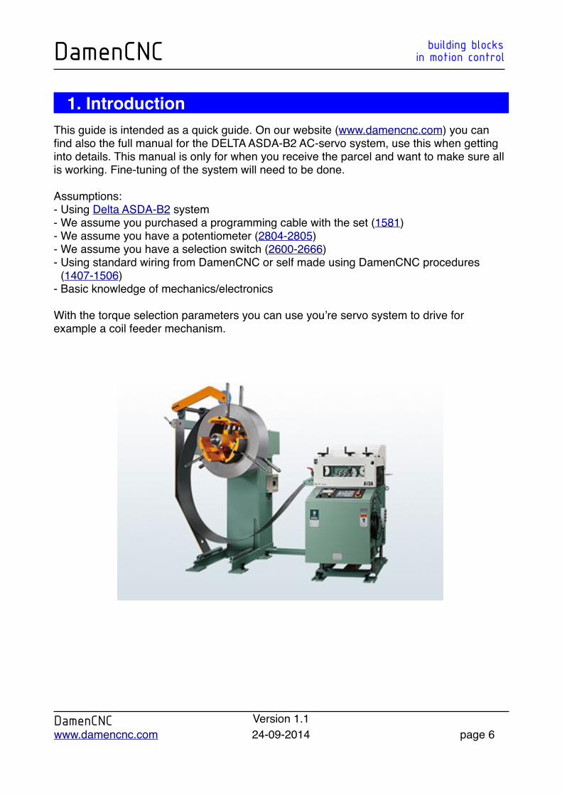
1. IntroductionThis guide is intended as a quick guide. On our website (www.damencnc.com) you can find also the full manual for the DELTA ASDA-B2 AC-servo system, use this when getting into details. This manual is only for when you receive the parcel and want to make sure all is working. Fine-tuning of the system will need to be done.
Assumptions:- Using Delta ASDA-B2 system- We assume you purchased a programming cable with the set (1581)- We assume you have a potentiometer (2804-2805)- We assume you have a selection switch (2600-2666)- Using standard wiring from DamenCNC or self made using DamenCNC procedures
(1407-1506)- Basic knowledge of mechanics/electronics
With the torque selection parameters you can use you’re servo system to drive for example a coil feeder mechanism.
DamenCNC building blocksDamenCNC in motion control
DamenCNC Version 1.1www.damencnc.com 24-09-2014 page 6
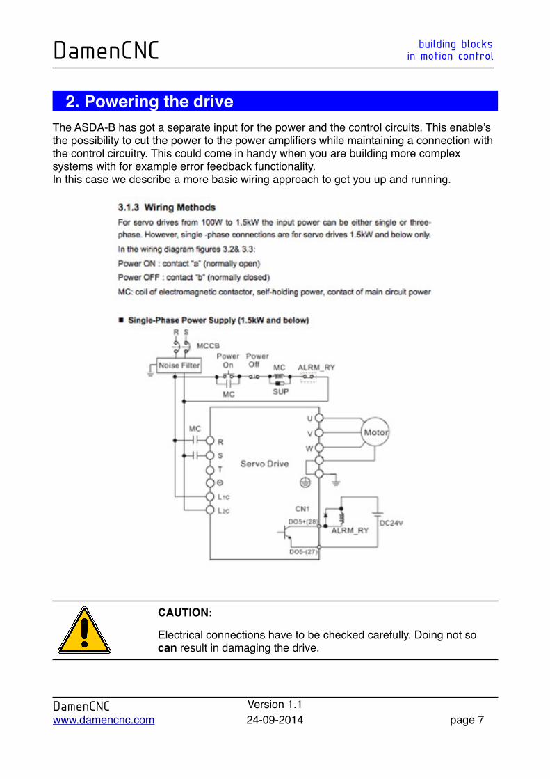
2. Powering the driveThe ASDA-B has got a separate input for the power and the control circuits. This enable’s the possibility to cut the power to the power amplifiers while maintaining a connection with the control circuitry. This could come in handy when you are building more complex systems with for example error feedback functionality. In this case we describe a more basic wiring approach to get you up and running.
CAUTION:
Electrical connections have to be checked carefully. Doing not so can result in damaging the drive.
DamenCNC building blocksDamenCNC in motion control
DamenCNC Version 1.1www.damencnc.com 24-09-2014 page 7

2.1 Drive powering checkWith the power connections made you can now power the drive. Please note that no motor is connected to the drive. When the drive is powered up it should display the AL011 message, which indicates that there is no encoder connected to the drive. This is the correct message for this situation.
3 Wiring the motor and encoder to the drive
3.1 Wiring the motor to the driveFor the power connection we use a industrial 4P circular connector. This connector is compatible with our servo cable sets.
Pin Motor side Drive Symbol
1 Red U
2 White V
3 Black W
4 Green/Yellow Connect to ground terminal of drive
CAUTION:
Electrical connections have to be checked carefully. Doing not so can result in damaging the drive.
DamenCNC building blocksDamenCNC in motion control
DamenCNC Version 1.1www.damencnc.com 24-09-2014 page 8
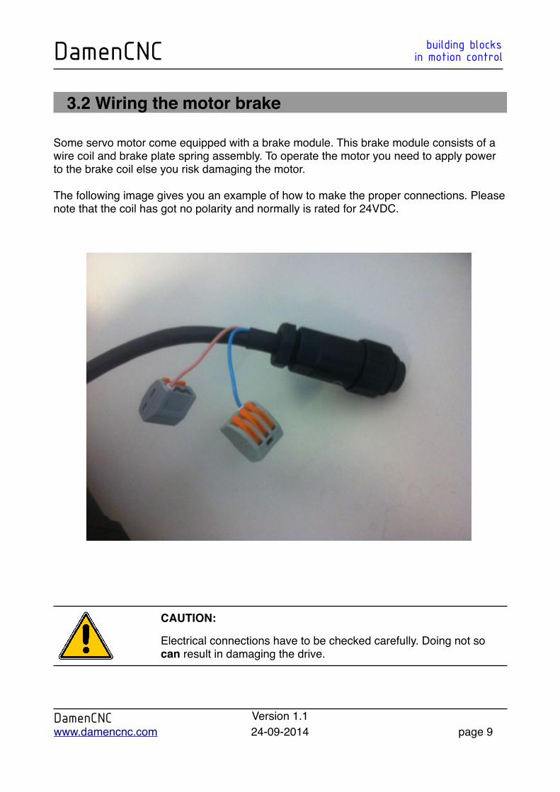
3.2 Wiring the motor brake
Some servo motor come equipped with a brake module. This brake module consists of a wire coil and brake plate spring assembly. To operate the motor you need to apply power to the brake coil else you risk damaging the motor.
The following image gives you an example of how to make the proper connections. Please note that the coil has got no polarity and normally is rated for 24VDC.
CAUTION:
Electrical connections have to be checked carefully. Doing not so can result in damaging the drive.
DamenCNC building blocksDamenCNC in motion control
DamenCNC Version 1.1www.damencnc.com 24-09-2014 page 9
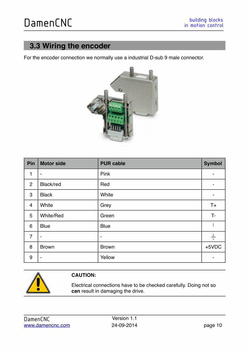
3.3 Wiring the encoderFor the encoder connection we normally use a industrial D-sub 9 male connector.
Pin Motor side PUR cable Symbol
1 - Pink -
2 Black/red Red -
3 Black White -
4 White Grey T+
5 White/Red Green T-
6 Blue Blue
7 - -
8 Brown Brown +5VDC
9 - Yellow -
CAUTION:
Electrical connections have to be checked carefully. Doing not so can result in damaging the drive.
DamenCNC building blocksDamenCNC in motion control
DamenCNC Version 1.1www.damencnc.com 24-09-2014 page 10

3.4 Wiring the control cableTo make the proper connections we only need the CN1 connector, as shown in on the image below.
ASDA-B2ASDA-B2 0-10V V2 CableCable
Pin Description Remark Cable color Symbol
14 Ground GND Brown
17 +24V 12-24VDC Yellow
18 Analog input AVI White
19 Ground GND Brown
34 Digital input 3 FWD Green
DamenCNC building blocksDamenCNC in motion control
DamenCNC Version 1.1www.damencnc.com 24-09-2014 page 11
3.5 Drive powering checkWith all cables connected, power the drive once more. You should now see a different error message. Before the drive display AL011 message and now i displays the AL013 message. If you still see the AL011 message something is wrong with you’re wiring, please start with verifying the encoder cable connections.
The AL013 message means that the emergency stop is active. To get rid of this parameter we need to chance some of the drive parameters. The following chapter explains how to do this.
DamenCNC building blocksDamenCNC in motion control
DamenCNC Version 1.1www.damencnc.com 24-09-2014 page 12
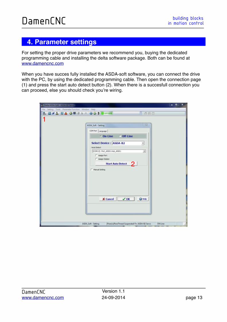
4. Parameter settingsFor setting the proper drive parameters we recommend you, buying the dedicated programming cable and installing the delta software package. Both can be found at www.damencnc.com
When you have succes fully installed the ASDA-soft software, you can connect the drive with the PC, by using the dedicated programming cable. Then open the connection page (1) and press the start auto detect button (2). When there is a succesfull connection you can proceed, else you should check you’re wiring.
DamenCNC building blocksDamenCNC in motion control
DamenCNC Version 1.1www.damencnc.com 24-09-2014 page 13
1
2
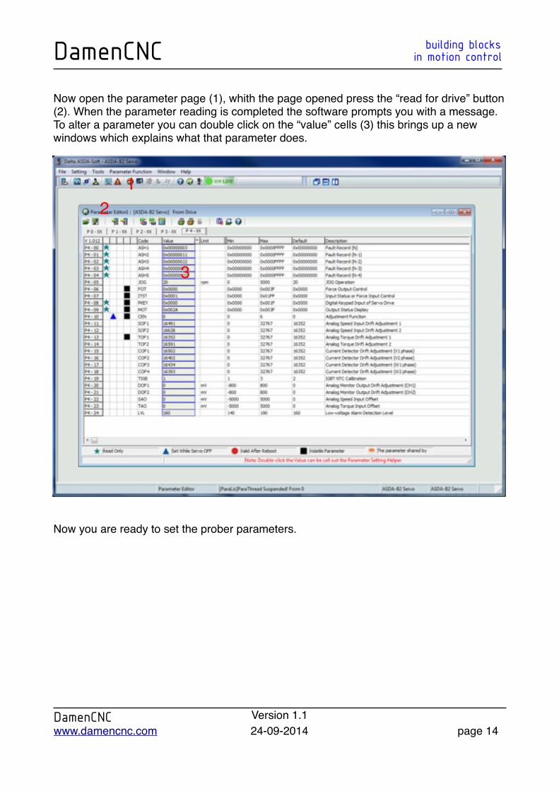
Now open the parameter page (1), whith the page opened press the “read for drive” button (2). When the parameter reading is completed the software prompts you with a message.To alter a parameter you can double click on the “value” cells (3) this brings up a new windows which explains what that parameter does.
Now you are ready to set the prober parameters.
DamenCNC building blocksDamenCNC in motion control
DamenCNC Version 1.1www.damencnc.com 24-09-2014 page 14
12
3
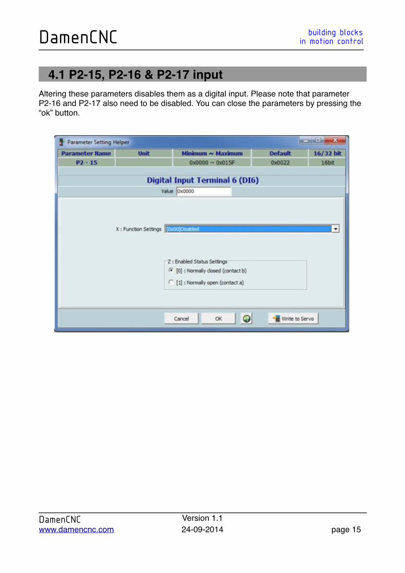
4.1 P2-15, P2-16 & P2-17 inputAltering these parameters disables them as a digital input. Please note that parameter P2-16 and P2-17 also need to be disabled. You can close the parameters by pressing the “ok” button.
DamenCNC building blocksDamenCNC in motion control
DamenCNC Version 1.1www.damencnc.com 24-09-2014 page 15
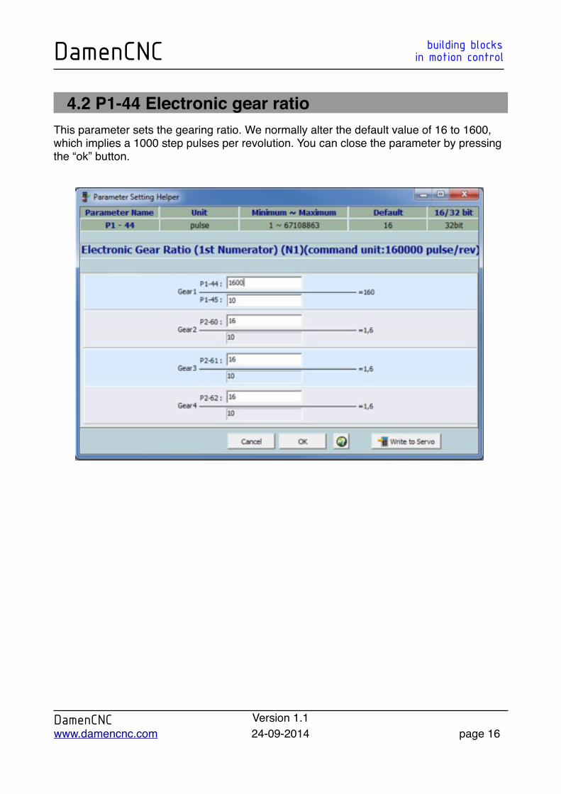
4.2 P1-44 Electronic gear ratioThis parameter sets the gearing ratio. We normally alter the default value of 16 to 1600, which implies a 1000 step pulses per revolution. You can close the parameter by pressing the “ok” button.
DamenCNC building blocksDamenCNC in motion control
DamenCNC Version 1.1www.damencnc.com 24-09-2014 page 16

4.3 P1-01 control modeAltering this parameter enables the possibility to switch between position and torque mode. Open this parameter and change its value to 0x0003. You can close the parameter by pressing the “ok” button.
Please note that this parameter will be valid after rebooting the drive.
DamenCNC building blocksDamenCNC in motion control
DamenCNC Version 1.1www.damencnc.com 24-09-2014 page 17
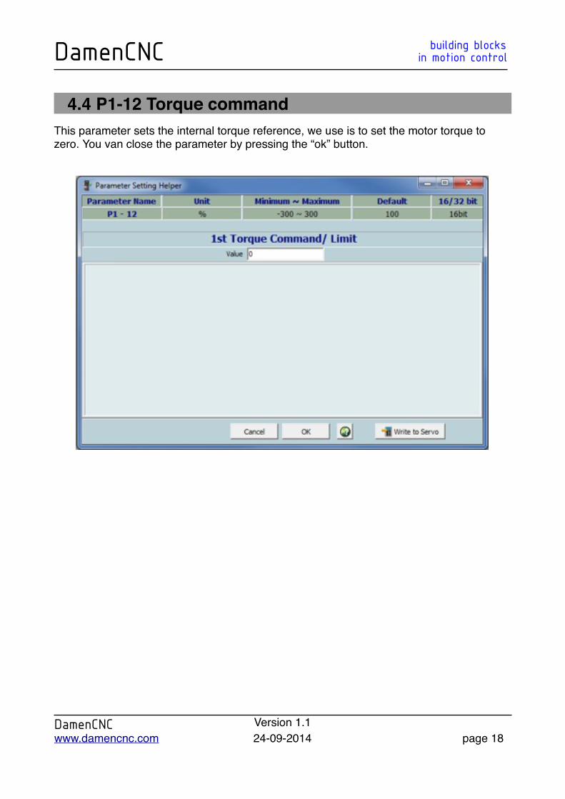
4.4 P1-12 Torque commandThis parameter sets the internal torque reference, we use is to set the motor torque to zero. You van close the parameter by pressing the “ok” button.
DamenCNC building blocksDamenCNC in motion control
DamenCNC Version 1.1www.damencnc.com 24-09-2014 page 18
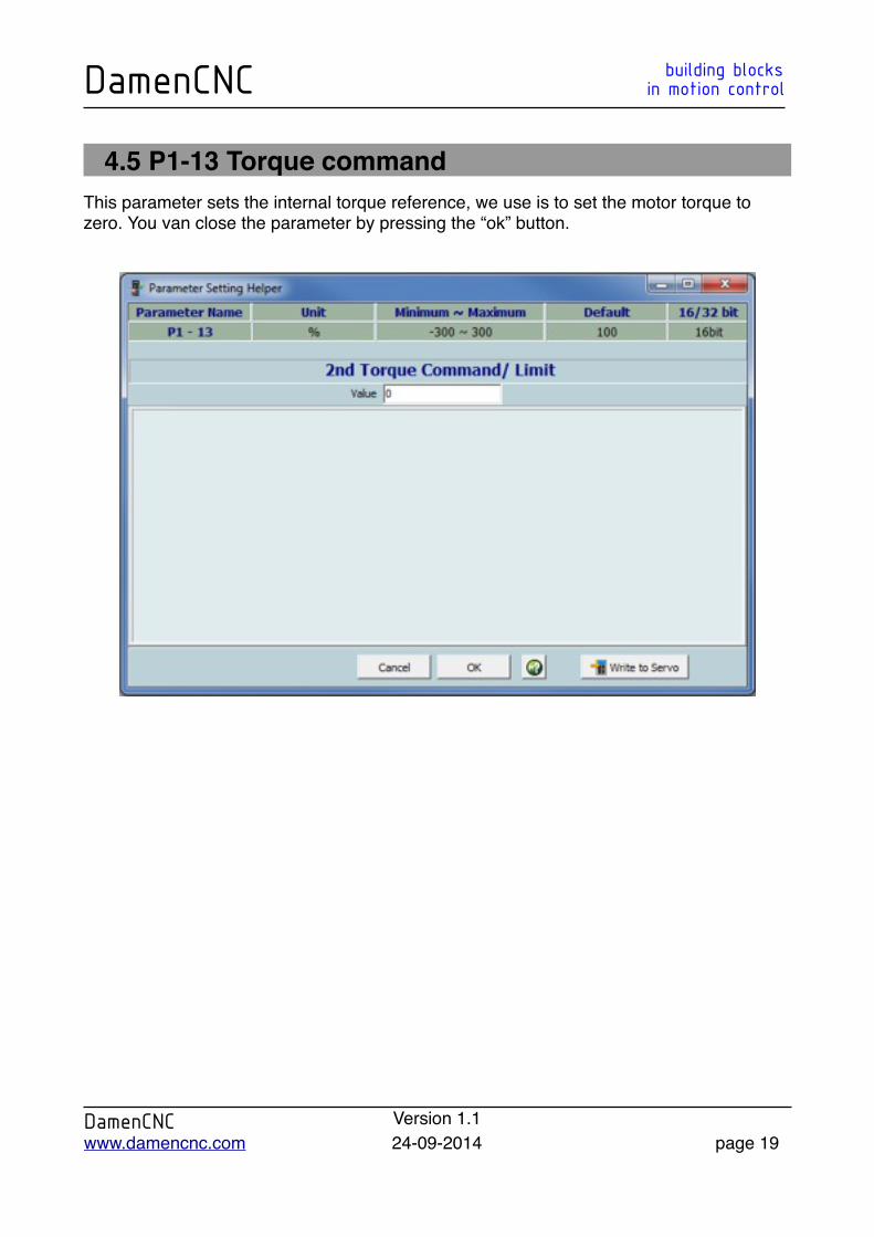
4.5 P1-13 Torque commandThis parameter sets the internal torque reference, we use is to set the motor torque to zero. You van close the parameter by pressing the “ok” button.
DamenCNC building blocksDamenCNC in motion control
DamenCNC Version 1.1www.damencnc.com 24-09-2014 page 19
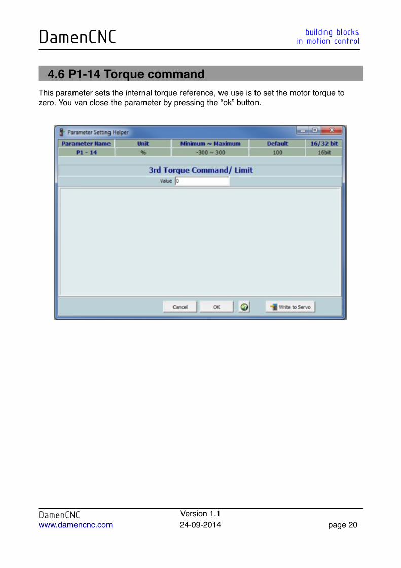
4.6 P1-14 Torque commandThis parameter sets the internal torque reference, we use is to set the motor torque to zero. You van close the parameter by pressing the “ok” button.
DamenCNC building blocksDamenCNC in motion control
DamenCNC Version 1.1www.damencnc.com 24-09-2014 page 20
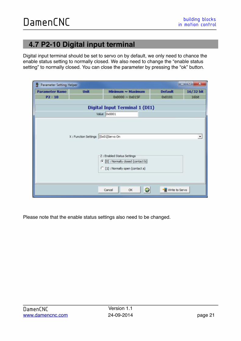
4.7 P2-10 Digital input terminalDigital input terminal should be set to servo on by default, we only need to chance the enable status setting to normally closed. We also need to change the “enable status setting” to normally closed. You can close the parameter by pressing the “ok” button.
Please note that the enable status settings also need to be changed.
DamenCNC building blocksDamenCNC in motion control
DamenCNC Version 1.1www.damencnc.com 24-09-2014 page 21
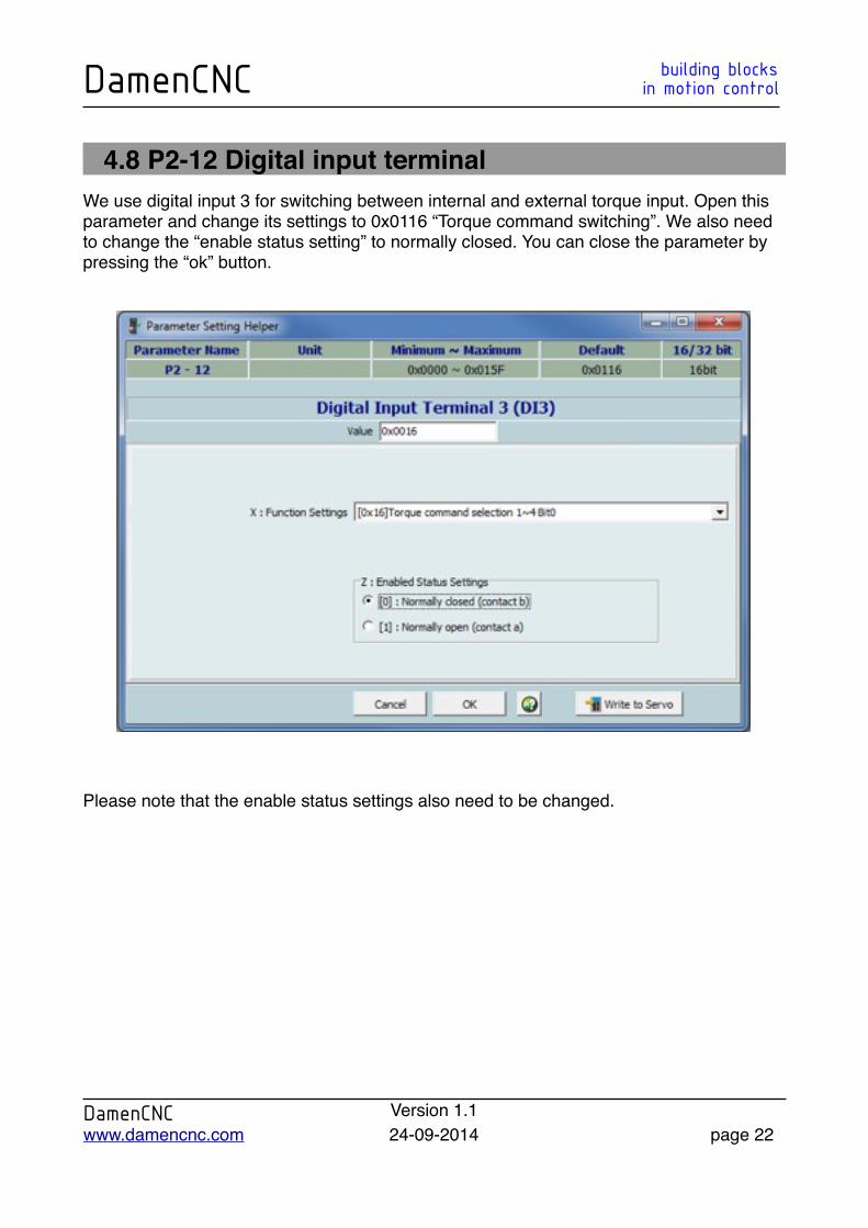
4.8 P2-12 Digital input terminalWe use digital input 3 for switching between internal and external torque input. Open this parameter and change its settings to 0x0116 “Torque command switching”. We also need to change the “enable status setting” to normally closed. You can close the parameter by pressing the “ok” button.
Please note that the enable status settings also need to be changed.
DamenCNC building blocksDamenCNC in motion control
DamenCNC Version 1.1www.damencnc.com 24-09-2014 page 22
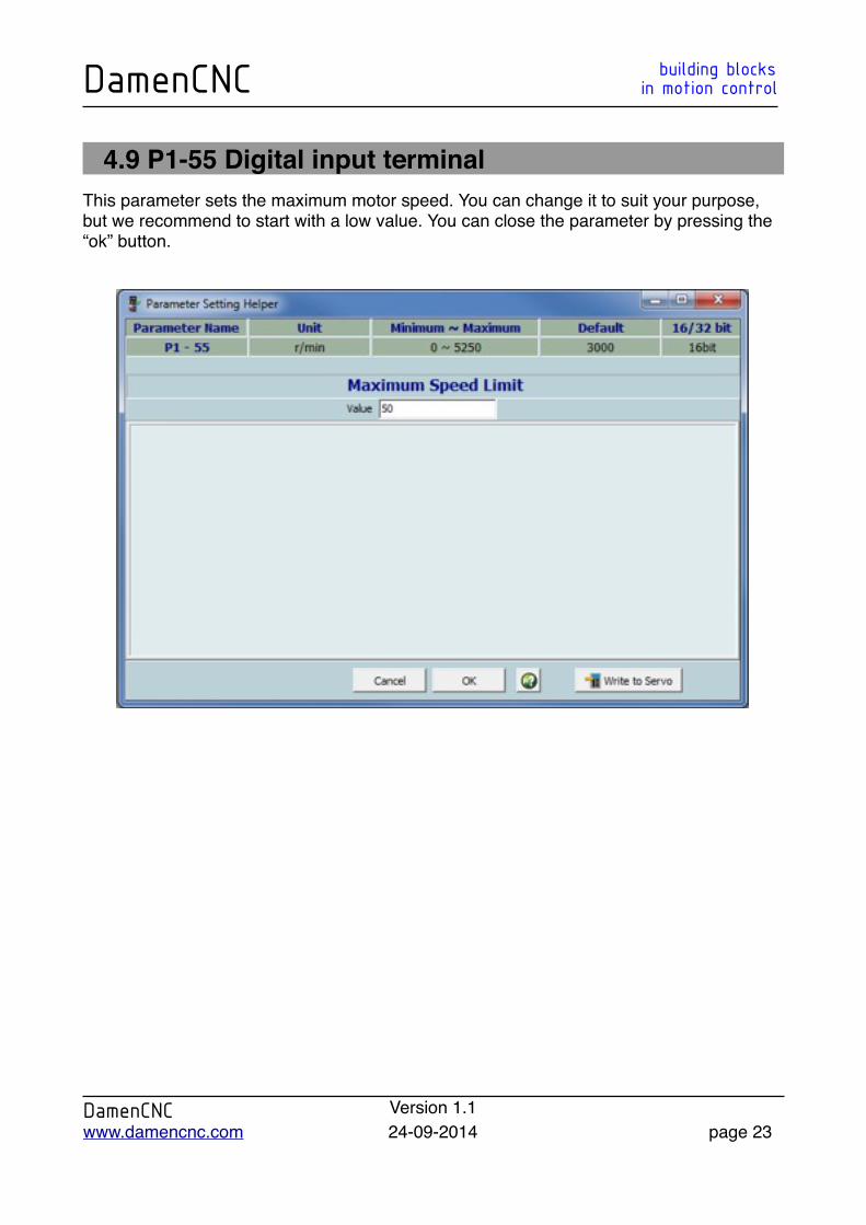
4.9 P1-55 Digital input terminalThis parameter sets the maximum motor speed. You can change it to suit your purpose, but we recommend to start with a low value. You can close the parameter by pressing the “ok” button.
DamenCNC building blocksDamenCNC in motion control
DamenCNC Version 1.1www.damencnc.com 24-09-2014 page 23
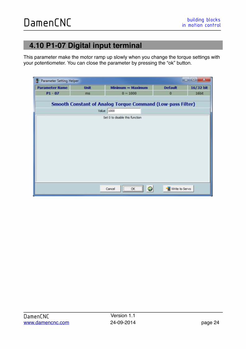
4.10 P1-07 Digital input terminalThis parameter make the motor ramp up slowly when you change the torque settings with your potentiometer. You can close the parameter by pressing the “ok” button.
DamenCNC building blocksDamenCNC in motion control
DamenCNC Version 1.1www.damencnc.com 24-09-2014 page 24
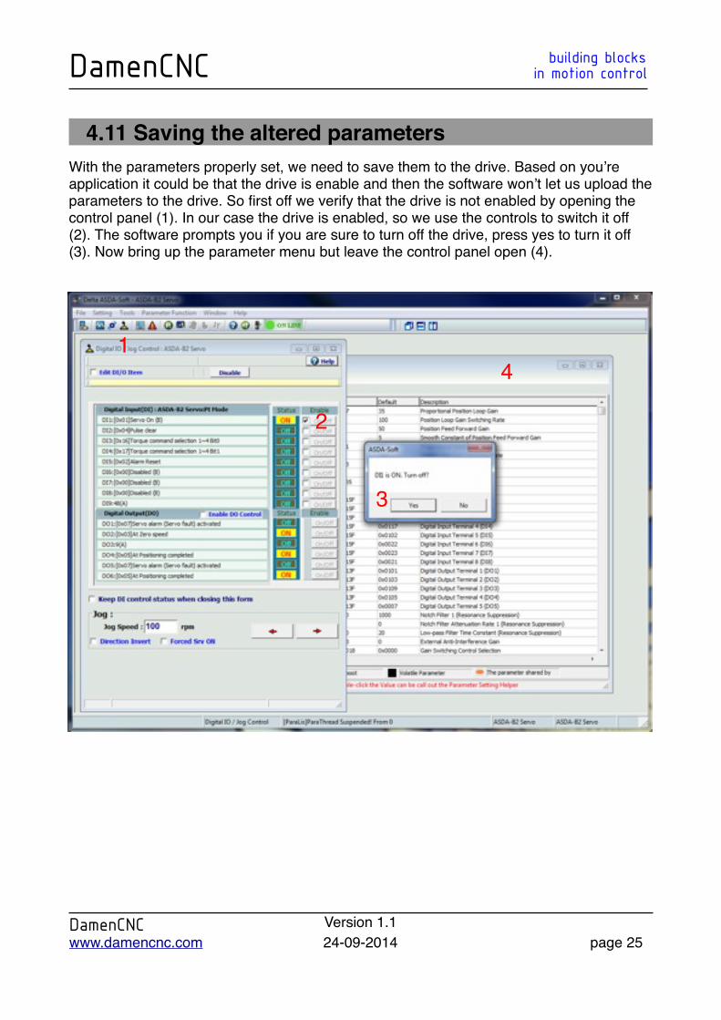
4.11 Saving the altered parametersWith the parameters properly set, we need to save them to the drive. Based on you’re application it could be that the drive is enable and then the software won’t let us upload the parameters to the drive. So first off we verify that the drive is not enabled by opening the control panel (1). In our case the drive is enabled, so we use the controls to switch it off (2). The software prompts you if you are sure to turn off the drive, press yes to turn it off (3). Now bring up the parameter menu but leave the control panel open (4).
DamenCNC building blocksDamenCNC in motion control
DamenCNC Version 1.1www.damencnc.com 24-09-2014 page 25
2
1
3
4
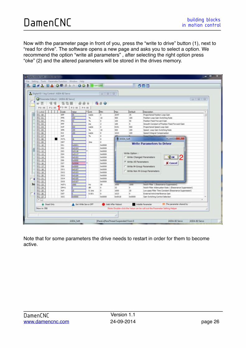
Now with the parameter page in front of you, press the “write to drive” button (1), next to “read for drive”. The software opens a new page and asks you to select a option. We recommend the option “write all parameters” , after selecting the right option press “oke” (2) and the altered parameters will be stored in the drives memory.
Note that for some parameters the drive needs to restart in order for them to become active.
DamenCNC building blocksDamenCNC in motion control
DamenCNC Version 1.1www.damencnc.com 24-09-2014 page 26
1
2