Embed Size (px)
Citation preview
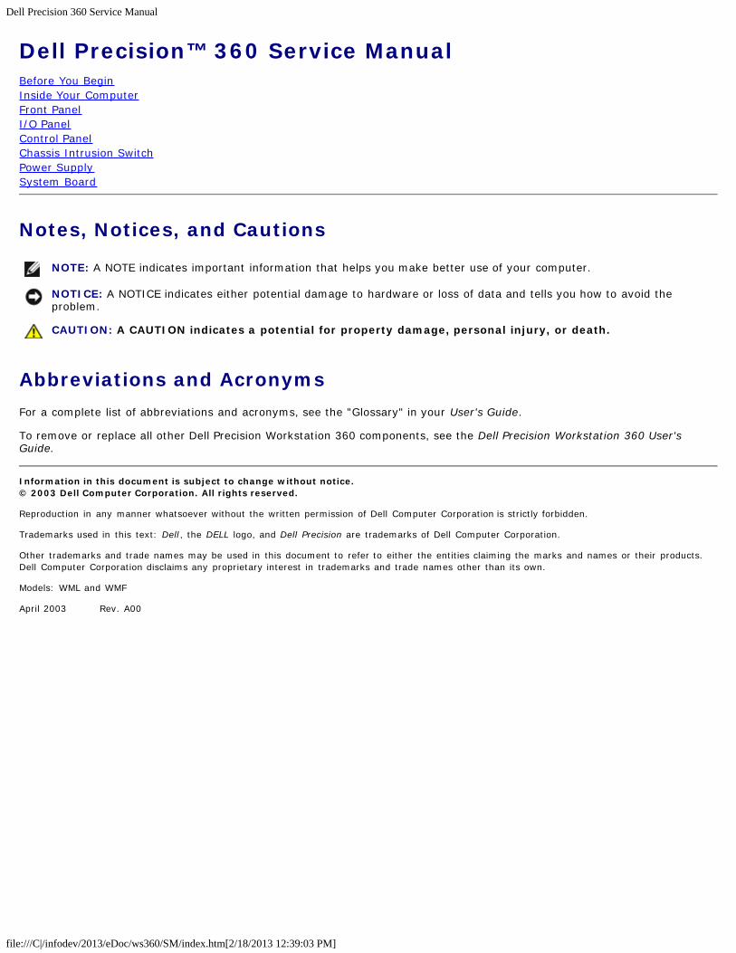
Dell Precision 360 Service Manual
file:///C|/infodev/2013/eDoc/ws360/SM/index.htm[2/18/2013 12:39:03 PM]
Dell Precision™ 360 Service ManualBefore You BeginInside Your ComputerFront PanelI/O PanelControl PanelChassis Intrusion SwitchPower SupplySystem Board
Notes, Notices, and Cautions
NOTE: A NOTE indicates important information that helps you make better use of your computer.
NOTICE: A NOTICE indicates either potential damage to hardware or loss of data and tells you how to avoid theproblem.
CAUTION: A CAUTION indicates a potential for property damage, personal injury, or death.
Abbreviations and AcronymsFor a complete list of abbreviations and acronyms, see the "Glossary" in your User's Guide.
To remove or replace all other Dell Precision Workstation 360 components, see the Dell Precision Workstation 360 User'sGuide.
Information in this document is subject to change without notice.© 2003 Dell Computer Corporation. All rights reserved.
Reproduction in any manner whatsoever without the written permission of Dell Computer Corporation is strictly forbidden.
Trademarks used in this text: Dell, the DELL logo, and Dell Precision are trademarks of Dell Computer Corporation.
Other trademarks and trade names may be used in this document to refer to either the entities claiming the marks and names or their products.Dell Computer Corporation disclaims any proprietary interest in trademarks and trade names other than its own.
Models: WML and WMF
April 2003 Rev. A00
Before You Begin: Dell Precision 360 Service Manual
file:///C|/infodev/2013/eDoc/ws360/SM/before.htm[2/18/2013 12:39:21 PM]
Back to Contents Page
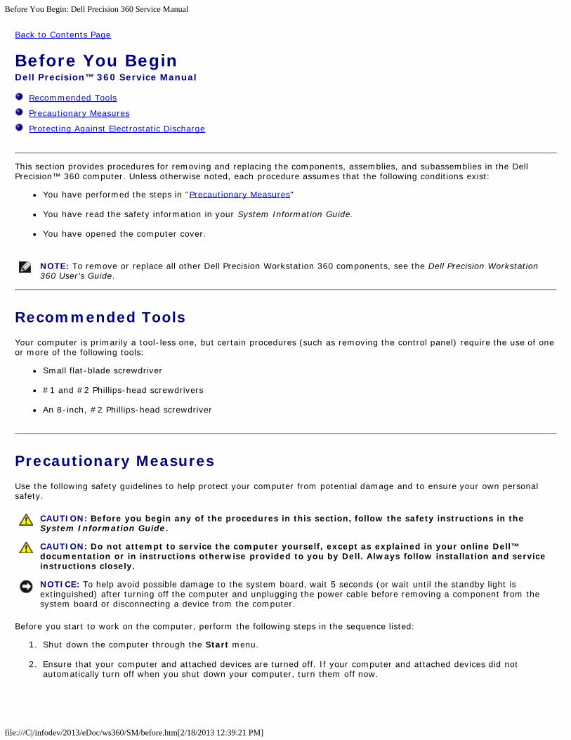
Before You BeginDell Precision™ 360 Service Manual
Recommended Tools
Precautionary Measures
Protecting Against Electrostatic Discharge
This section provides procedures for removing and replacing the components, assemblies, and subassemblies in the DellPrecision™ 360 computer. Unless otherwise noted, each procedure assumes that the following conditions exist:
You have performed the steps in "Precautionary Measures"
You have read the safety information in your System Information Guide.
You have opened the computer cover.
NOTE: To remove or replace all other Dell Precision Workstation 360 components, see the Dell Precision Workstation360 User's Guide.
Recommended ToolsYour computer is primarily a tool-less one, but certain procedures (such as removing the control panel) require the use of oneor more of the following tools:
Small flat-blade screwdriver
#1 and #2 Phillips-head screwdrivers
An 8-inch, #2 Phillips-head screwdriver
Precautionary MeasuresUse the following safety guidelines to help protect your computer from potential damage and to ensure your own personalsafety.
CAUTION: Before you begin any of the procedures in this section, follow the safety instructions in theSystem Information Guide.
CAUTION: Do not attempt to service the computer yourself, except as explained in your online Dell™documentation or in instructions otherwise provided to you by Dell. Always follow installation and serviceinstructions closely.
NOTICE: To help avoid possible damage to the system board, wait 5 seconds (or wait until the standby light isextinguished) after turning off the computer and unplugging the power cable before removing a component from thesystem board or disconnecting a device from the computer.
Before you start to work on the computer, perform the following steps in the sequence listed:
1. Shut down the computer through the Start menu.
2. Ensure that your computer and attached devices are turned off. If your computer and attached devices did notautomatically turn off when you shut down your computer, turn them off now.
Before You Begin: Dell Precision 360 Service Manual
file:///C|/infodev/2013/eDoc/ws360/SM/before.htm[2/18/2013 12:39:21 PM]
NOTICE: To disconnect a network cable, first unplug the cable from your computer and then unplug it from thenetwork wall jack.
3. Disconnect any telephone or telecommunication lines from the computer.
4. Disconnect your computer and all attached devices from electrical outlets, and then press the power button to groundthe system board.
In addition, take note of these safety guidelines when appropriate:
When you disconnect a cable, pull on its connector or on its strain-relief loop, not on the cable itself. Some cables havea connector with locking tabs; if you are disconnecting this type of cable, press in on the locking tabs beforedisconnecting the cable. As you pull connectors apart, keep them evenly aligned to avoid bending any connector pins.Also, before you connect a cable, ensure that both connectors are correctly oriented and aligned.
Handle components and cards with care. Do not touch the components or contacts on a card. Hold a card by its edgesor by its metal mounting bracket. Hold a component such as a microprocessor chip by its edges, not by its pins.
Protecting Against Electrostatic DischargeStatic electricity can harm delicate components inside your computer. To prevent static damage, discharge static electricityfrom your body before you touch any of your computer's electronic components, such as the microprocessor. You can do soby touching an unpainted metal surface on the computer chassis.
As you continue to work inside the computer, periodically touch an unpainted metal surface to remove any static charge yourbody may have accumulated.
You can also take the following steps to prevent damage from electrostatic discharge (ESD):
When unpacking a static-sensitive component from its shipping carton, do not remove the component from theantistatic packing material until you are ready to install the component in your computer. Just before unwrapping theantistatic packaging, be sure to discharge static electricity from your body.
When transporting a sensitive component, first place it in an antistatic container or packaging.
Handle all sensitive components in a static-safe area. If possible, use antistatic floor pads and workbench pads.
Back to Contents Page

Inside Your Computer: Dell Precision 360 Service Manual
file:///C|/infodev/2013/eDoc/ws360/SM/inside.htm[2/18/2013 12:39:34 PM]
Back to Contents Page
Inside Your ComputerDell Precision™ 360 Service Manual
Mini-Tower Computer
Desktop Computer
Cable Colors – Mini-Tower and Desktop Computers
System Board Components
Jumper Settings
CAUTION: Before performing any of the procedures in this section, follow the safety instructions in theSystem Information Guide.
CAUTION: To avoid electrical shock, always unplug your computer from the electrical outlet before openingthe cover.
CAUTION: To prevent static damage to components inside your computer, discharge static electricity fromyour body before you touch any of your computer's electronic components. You can do so by touching anunpainted metal surface on the computer chassis.
NOTICE: Be careful when opening the computer cover to ensure that you do not accidentally disconnect cables fromthe system board.
Mini-Tower Computer
Inside Your Computer: Dell Precision 360 Service Manual
file:///C|/infodev/2013/eDoc/ws360/SM/inside.htm[2/18/2013 12:39:34 PM]
1 hard drive 6 heat sink and blowerassembly
2 internal speaker(optional)
7 power supply
3 chassis intrusion switch 8 floppy drive (optional)
4 system board 9 CD/DVD drive
5 padlock ring
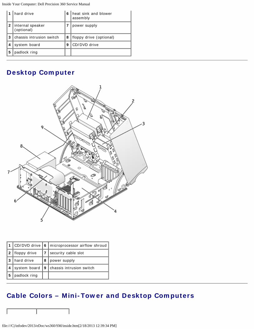
Desktop Computer
1 CD/DVD drive 6 microprocessor airflow shroud
2 floppy drive 7 security cable slot
3 hard drive 8 power supply
4 system board 9 chassis intrusion switch
5 padlock ring
Cable Colors – Mini-Tower and Desktop Computers
Inside Your Computer: Dell Precision 360 Service Manual
file:///C|/infodev/2013/eDoc/ws360/SM/inside.htm[2/18/2013 12:39:34 PM]
Device Cable Color
Hard drive Blue pull tab
Floppy drive Black pull tab
CD/DVD drive Orange pull tab
I/O panel Yellow pull tab
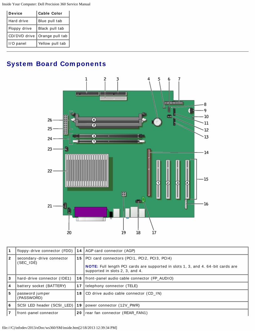
System Board Components
1 floppy-drive connector (FDD) 14 AGP card connector (AGP)
2 secondary-drive connector(SEC_IDE)
15 PCI card connectors (PCI1, PCI2, PCI3, PCI4)
NOTE: Full length PCI cards are supported in slots 1, 3, and 4. 64-bit cards aresupported in slots 2, 3, and 4.
3 hard-drive connector (IDE1) 16 front-panel audio cable connector (FP_AUDIO)
4 battery socket (BATTERY) 17 telephony connector (TELE)
5 password jumper(PASSWORD)
18 CD drive audio cable connector (CD_IN)
6 SCSI LED header (SCSI_LED) 19 power connector (12V_PWR)
7 front-panel connector 20 rear fan connector (REAR_FAN1)
Inside Your Computer: Dell Precision 360 Service Manual
file:///C|/infodev/2013/eDoc/ws360/SM/inside.htm[2/18/2013 12:39:34 PM]
(FRONT_PANEL)
8 standby power light(PWR_LED)
21 rear fan connector (REAR_FAN2)
9 internal speaker (SPKR) 22 microprocessor and heat-sink connector (CPU_0 PIN_#A1)
10 clear CMOS jumper (CMOS) 23 microprocessor fan connector (CPU_FAN)
11 serial ATA connector(SATA_1)
24 memory module connectors (1, 3)
12 front fan (FRONT_FAN) 25 power connector (PWR)
13 serial ATA connector(SATA_0)
26 memory module connectors (2, 4)
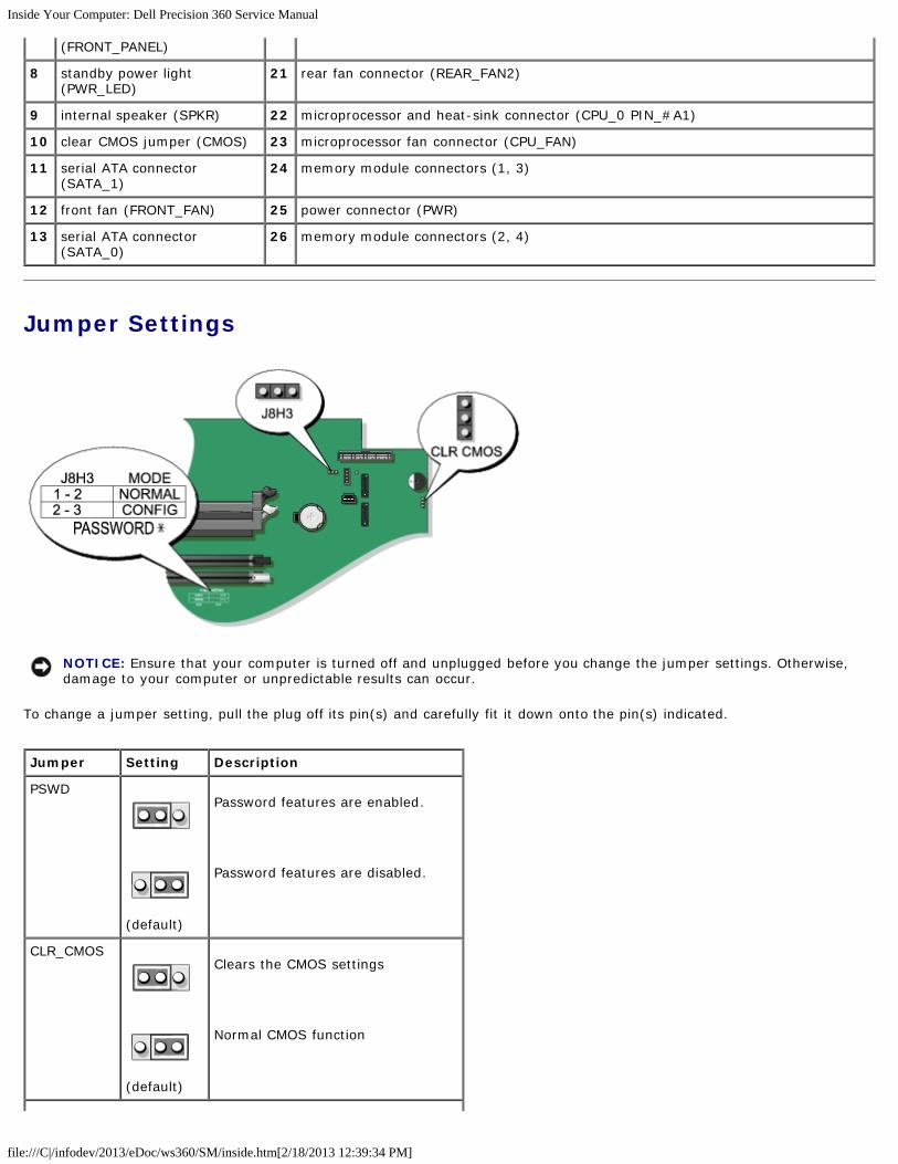
Jumper Settings
NOTICE: Ensure that your computer is turned off and unplugged before you change the jumper settings. Otherwise,damage to your computer or unpredictable results can occur.
To change a jumper setting, pull the plug off its pin(s) and carefully fit it down onto the pin(s) indicated.
Jumper Setting Description
PSWD
(default)
Password features are enabled.
Password features are disabled.
CLR_CMOS
(default)
Clears the CMOS settings
Normal CMOS function

Inside Your Computer: Dell Precision 360 Service Manual
file:///C|/infodev/2013/eDoc/ws360/SM/inside.htm[2/18/2013 12:39:34 PM]
jumpered unjumpered
Back to Contents Page
Front Panel : Dell Precision 360 Service Manual
file:///C|/infodev/2013/eDoc/ws360/SM/frtpnl.htm[2/18/2013 12:39:35 PM]
Back to Contents Page
Front PanelDell Precision™ 360 Service Manual
Removing the Front Panel – Mini-Tower Computer
Removing the Front Panel – Desktop Computer
Replacing the Front Panel
CAUTION: Before performing any of the procedures in this section, follow the safety instructions in theSystem Information Guide.
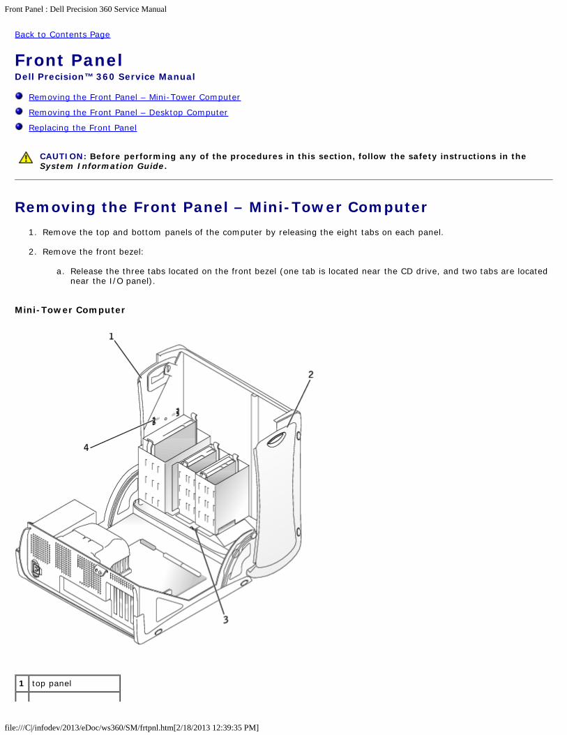
Removing the Front Panel – Mini-Tower Computer1. Remove the top and bottom panels of the computer by releasing the eight tabs on each panel.
2. Remove the front bezel:
a. Release the three tabs located on the front bezel (one tab is located near the CD drive, and two tabs are locatednear the I/O panel).
Mini-Tower Computer
1 top panel
Front Panel : Dell Precision 360 Service Manual
file:///C|/infodev/2013/eDoc/ws360/SM/frtpnl.htm[2/18/2013 12:39:35 PM]
2 bottom panel
3 front-panel tabs (3)
4 top-panel tabs (8)
b. Close the cover and remove the front bezel.
3. Remove the screw that holds the control panel to the computer, and remove the control panel.
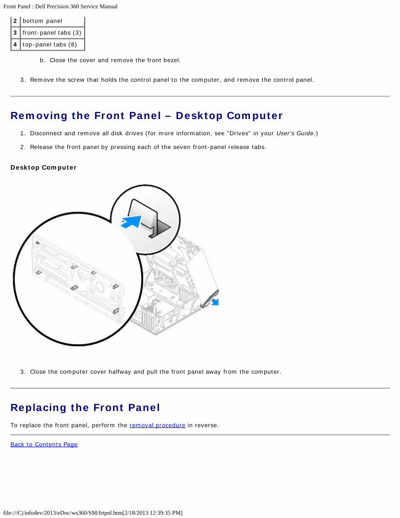
Removing the Front Panel – Desktop Computer1. Disconnect and remove all disk drives (for more information, see "Drives" in your User's Guide.)
2. Release the front panel by pressing each of the seven front-panel release tabs.
Desktop Computer
3. Close the computer cover halfway and pull the front panel away from the computer.
Replacing the Front PanelTo replace the front panel, perform the removal procedure in reverse.
Back to Contents Page
I/O Panel: Dell Precision 360 Service Manual
file:///C|/infodev/2013/eDoc/ws360/SM/iopnl.htm[2/18/2013 12:39:36 PM]
Back to Contents Page
I/O PanelDell Precision™ 360 Service Manual
I/O Panel Components
Removing the I/O Panel
Replacing the I/O Panel
CAUTION: Before performing any of the procedures in this section, follow the safety instructions in theSystem Information Guide.
CAUTION: To prevent static damage to components inside your computer, discharge static electricity fromyour body before you touch any of your computer's electronic components. You can do so by touching anunpainted metal surface on the computer chassis.
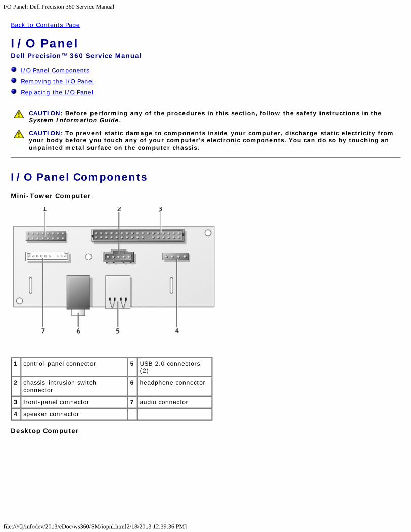
I/O Panel ComponentsMini-Tower Computer
1 control-panel connector 5 USB 2.0 connectors(2)
2 chassis-intrusion switchconnector
6 headphone connector
3 front-panel connector 7 audio connector
4 speaker connector
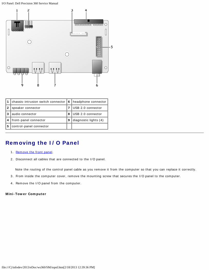
Desktop Computer
I/O Panel: Dell Precision 360 Service Manual
file:///C|/infodev/2013/eDoc/ws360/SM/iopnl.htm[2/18/2013 12:39:36 PM]
1 chassis-intrusion switch connector 6 headphone connector
2 speaker connector 7 USB 2.0 connector
3 audio connector 8 USB 2.0 connector
4 front-panel connector 9 diagnostic lights (4)
5 control-panel connector
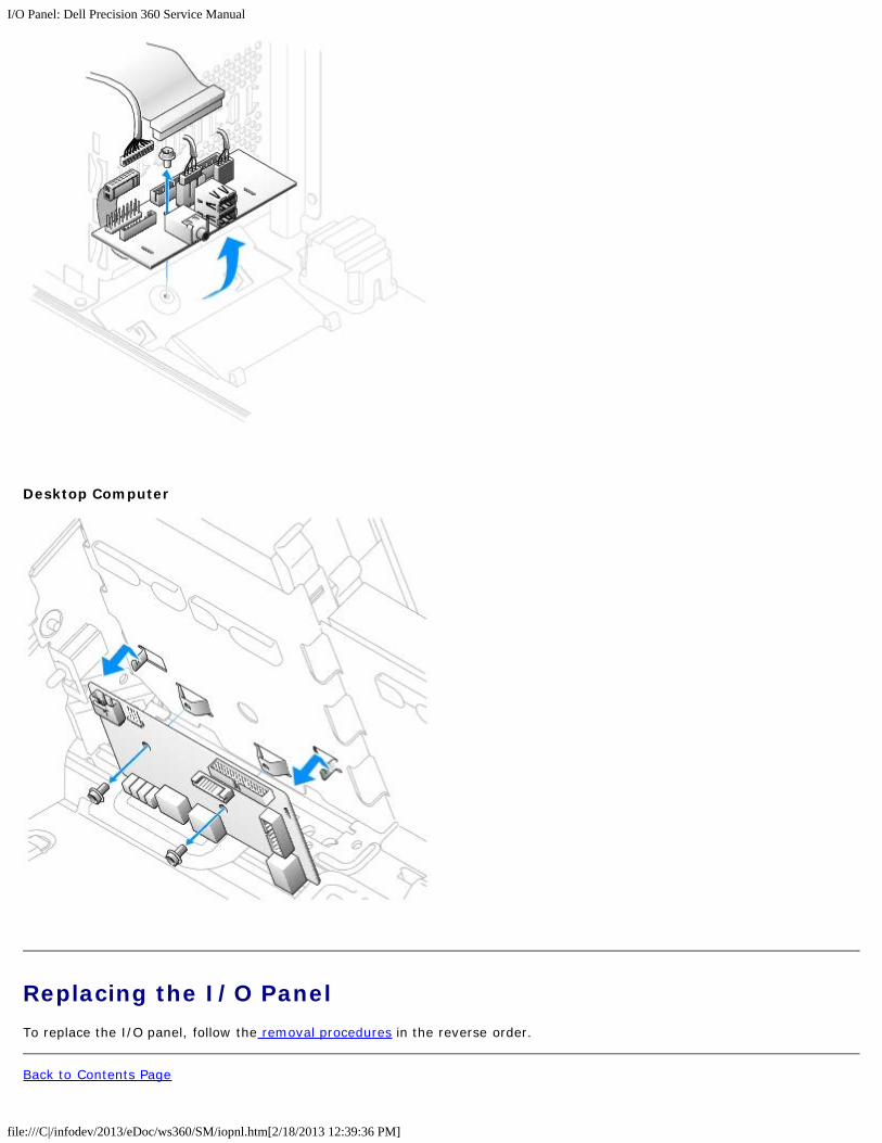
Removing the I/O Panel1. Remove the front panel.
2. Disconnect all cables that are connected to the I/O panel.
Note the routing of the control panel cable as you remove it from the computer so that you can replace it correctly.
3. From inside the computer cover, remove the mounting screw that secures the I/O panel to the computer.
4. Remove the I/O panel from the computer.
Mini-Tower Computer
I/O Panel: Dell Precision 360 Service Manual
file:///C|/infodev/2013/eDoc/ws360/SM/iopnl.htm[2/18/2013 12:39:36 PM]
Desktop Computer
Replacing the I/O PanelTo replace the I/O panel, follow the removal procedures in the reverse order.
Back to Contents Page

I/O Panel: Dell Precision 360 Service Manual
file:///C|/infodev/2013/eDoc/ws360/SM/iopnl.htm[2/18/2013 12:39:36 PM]
Control Panel: Dell Precision 360 Service Manual
file:///C|/infodev/2013/eDoc/ws360/SM/cntrlpnl.htm[2/18/2013 12:39:36 PM]
Back to Contents Page
Control PanelDell Precision™ 360 Service Manual
Control-Panel Components
Removing the Control Panel
Replacing the Control Panel
CAUTION: Before performing any of the procedures in this section, follow the safety instructions in theSystem Information Guide.
CAUTION: To prevent static damage to components inside your computer, discharge static electricity fromyour body before you touch any of your computer's electronic components. You can do so by touching anunpainted metal surface on the computer chassis.
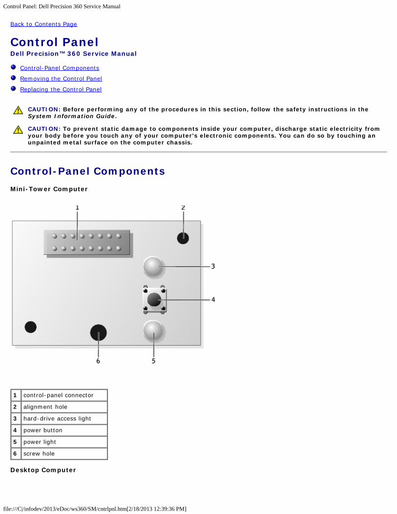
Control-Panel ComponentsMini-Tower Computer
1 control-panel connector
2 alignment hole
3 hard-drive access light
4 power button
5 power light
6 screw hole
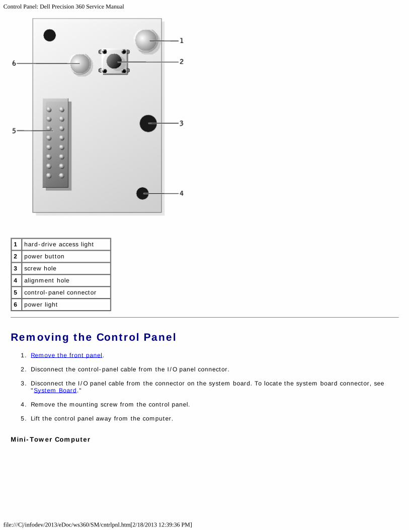
Desktop Computer
Control Panel: Dell Precision 360 Service Manual
file:///C|/infodev/2013/eDoc/ws360/SM/cntrlpnl.htm[2/18/2013 12:39:36 PM]
1 hard-drive access light
2 power button
3 screw hole
4 alignment hole
5 control-panel connector
6 power light
Removing the Control Panel1. Remove the front panel.
2. Disconnect the control-panel cable from the I/O panel connector.
3. Disconnect the I/O panel cable from the connector on the system board. To locate the system board connector, see"System Board."
4. Remove the mounting screw from the control panel.
5. Lift the control panel away from the computer.
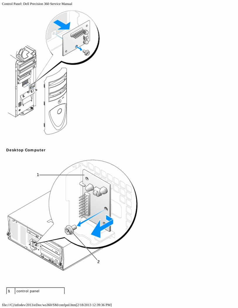
Mini-Tower Computer
Control Panel: Dell Precision 360 Service Manual
file:///C|/infodev/2013/eDoc/ws360/SM/cntrlpnl.htm[2/18/2013 12:39:36 PM]
Desktop Computer
1 control panel

Control Panel: Dell Precision 360 Service Manual
file:///C|/infodev/2013/eDoc/ws360/SM/cntrlpnl.htm[2/18/2013 12:39:36 PM]
2 mounting screw
Replacing the Control PanelFollow the removal procedure in reverse order, ensuring that the tabs on the top panel, bottom panel, and front panel aresecure.
Back to Contents Page

Chassis Intrusion Switch: Dell Precision 360 Service Manual
file:///C|/infodev/2013/eDoc/ws360/SM/chsintr.htm[2/18/2013 12:39:37 PM]
Back to Contents Page
Chassis Intrusion SwitchDell Precision™ 360 Service Manual
Removing the Chassis Intrusion Switch
Resetting the Chassis Intrusion Detector
Replacing the Chassis Intrusion Switch
CAUTION: Before performing any of the procedures in this section, follow the safety instructions in theSystem Information Guide.
CAUTION: To prevent static damage to components inside your computer, discharge static electricity fromyour body before you touch any of your computer's electronic components. You can do so by touching anunpainted metal surface on the computer chassis.
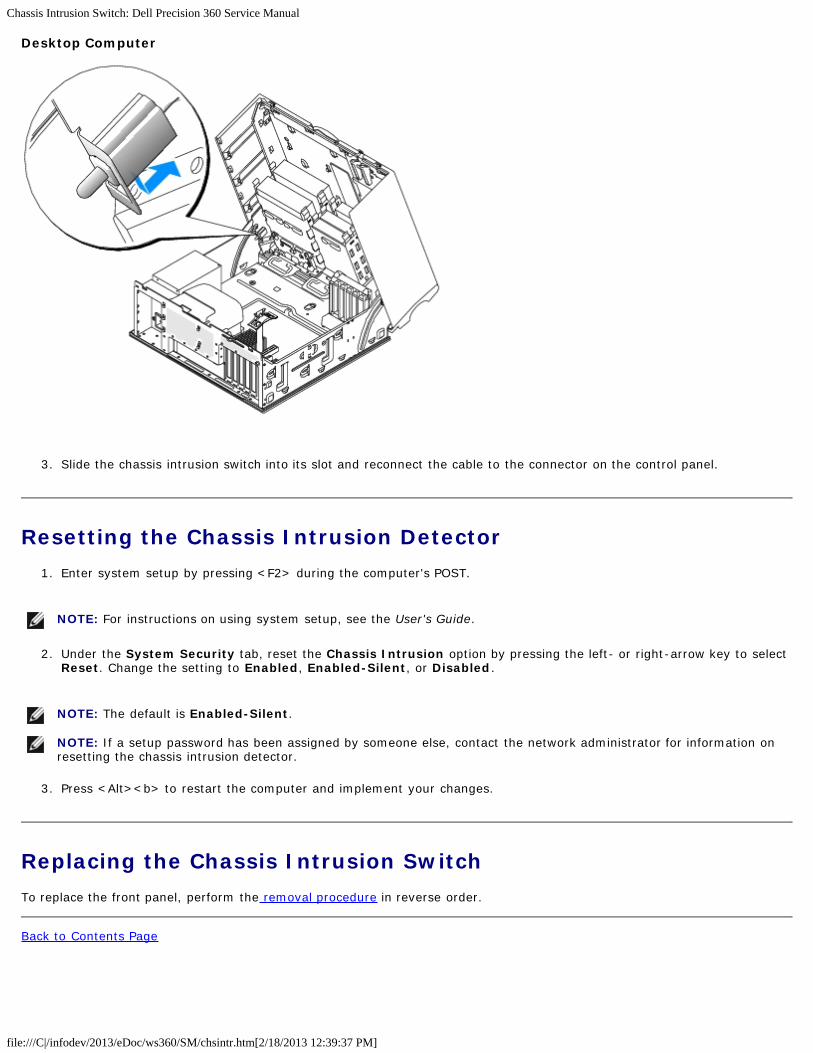
Removing the Chassis Intrusion Switch1. Disconnect the chassis intrusion switch cable from the control panel on the front of the computer.
Note the routing of the chassis intrusion cable as you remove it from the chassis. Chassis hooks may hold the cable inplace inside the chassis.
2. Slide the chassis intrusion switch out of its slot, and remove the switch and its attached cable from the computer.
Mini Tower Computer
Chassis Intrusion Switch: Dell Precision 360 Service Manual
file:///C|/infodev/2013/eDoc/ws360/SM/chsintr.htm[2/18/2013 12:39:37 PM]
Desktop Computer
3. Slide the chassis intrusion switch into its slot and reconnect the cable to the connector on the control panel.
Resetting the Chassis Intrusion Detector1. Enter system setup by pressing <F2> during the computer's POST.
NOTE: For instructions on using system setup, see the User's Guide.
2. Under the System Security tab, reset the Chassis Intrusion option by pressing the left- or right-arrow key to selectReset. Change the setting to Enabled, Enabled-Silent, or Disabled.
NOTE: The default is Enabled-Silent.
NOTE: If a setup password has been assigned by someone else, contact the network administrator for information onresetting the chassis intrusion detector.
3. Press <Alt><b> to restart the computer and implement your changes.
Replacing the Chassis Intrusion SwitchTo replace the front panel, perform the removal procedure in reverse order.
Back to Contents Page
Power Supply: Dell Precision 360 Service Manual
file:///C|/infodev/2013/eDoc/ws360/SM/pwrsply.htm[2/18/2013 12:39:38 PM]
Back to Contents Page
Power SupplyDell Precision™ 360 Service Manual
Removing the Power Supply
Replacing the Power Supply
CAUTION: Before performing any of the procedures in this section, follow the safety instructions in theSystem Information Guide.
CAUTION: To prevent static damage to components inside your computer, discharge static electricity fromyour body before you touch any of your computer's electronic components. You can do so by touching anunpainted metal surface on the computer chassis.
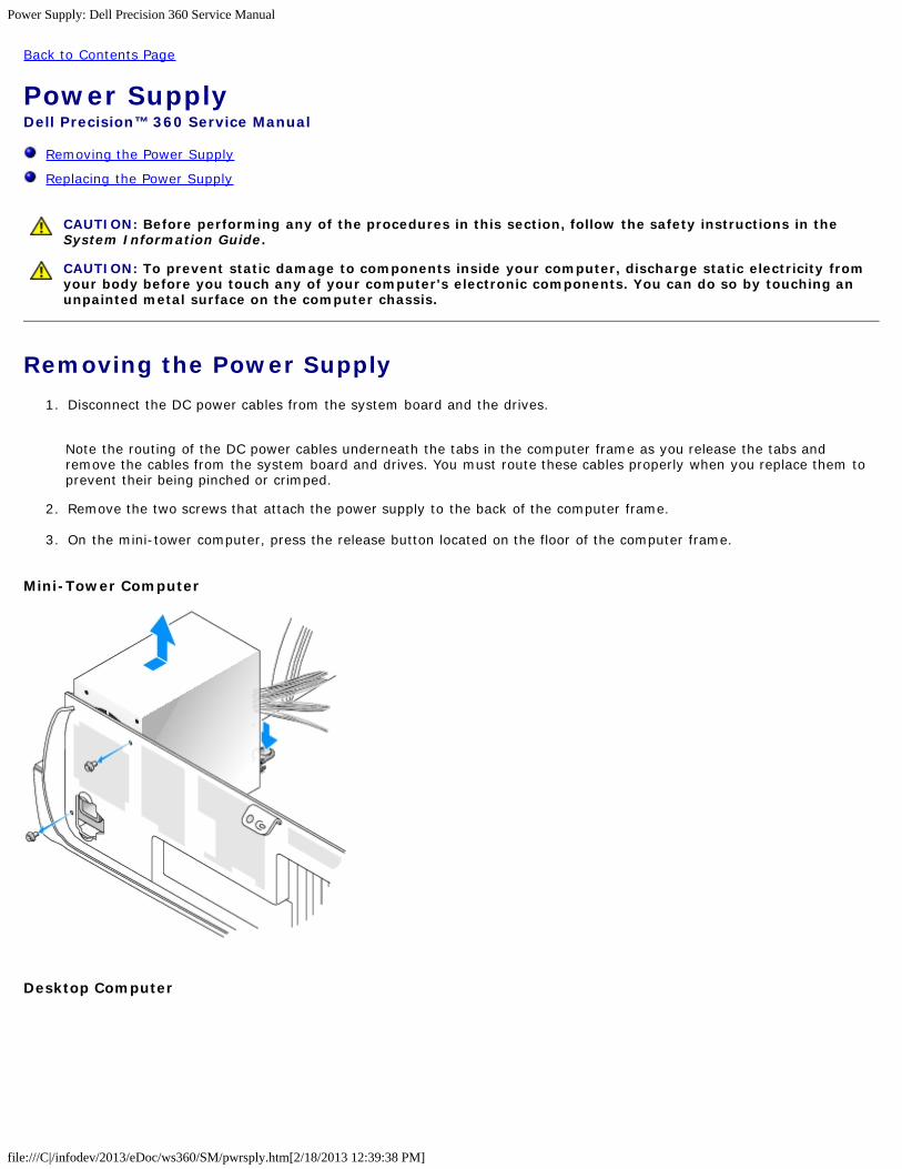
Removing the Power Supply1. Disconnect the DC power cables from the system board and the drives.
Note the routing of the DC power cables underneath the tabs in the computer frame as you release the tabs andremove the cables from the system board and drives. You must route these cables properly when you replace them toprevent their being pinched or crimped.
2. Remove the two screws that attach the power supply to the back of the computer frame.
3. On the mini-tower computer, press the release button located on the floor of the computer frame.
Mini-Tower Computer
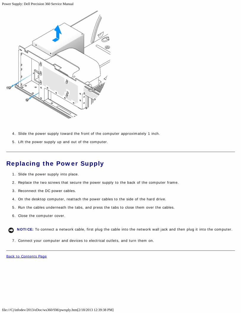
Desktop Computer
Power Supply: Dell Precision 360 Service Manual
file:///C|/infodev/2013/eDoc/ws360/SM/pwrsply.htm[2/18/2013 12:39:38 PM]
4. Slide the power supply toward the front of the computer approximately 1 inch.
5. Lift the power supply up and out of the computer.
Replacing the Power Supply1. Slide the power supply into place.
2. Replace the two screws that secure the power supply to the back of the computer frame.
3. Reconnect the DC power cables.
4. On the desktop computer, reattach the power cables to the side of the hard drive.
5. Run the cables underneath the tabs, and press the tabs to close them over the cables.
6. Close the computer cover.
NOTICE: To connect a network cable, first plug the cable into the network wall jack and then plug it into the computer.
7. Connect your computer and devices to electrical outlets, and turn them on.
Back to Contents Page
System Board: Dell Precision 360 Service Manual
file:///C|/infodev/2013/eDoc/ws360/SM/sysbrd.htm[2/18/2013 12:39:38 PM]
Back to Contents Page
System BoardDell Precision™ 360 Service Manual
Removing the System Board
Replacing the System Board
CAUTION: Before performing any of the procedures in this section, follow the safety instructions in theSystem Information Guide.
CAUTION: To prevent static damage to components inside your computer, discharge static electricity fromyour body before you touch any of your computer's electronic components. You can do so by touching anunpainted metal surface on the computer chassis.
NOTICE: The system board and metal tray are connected and removed as one piece.
Removing the System Board1. Remove any components that restrict access to the system board.
2. Disconnect all cables from the system board.
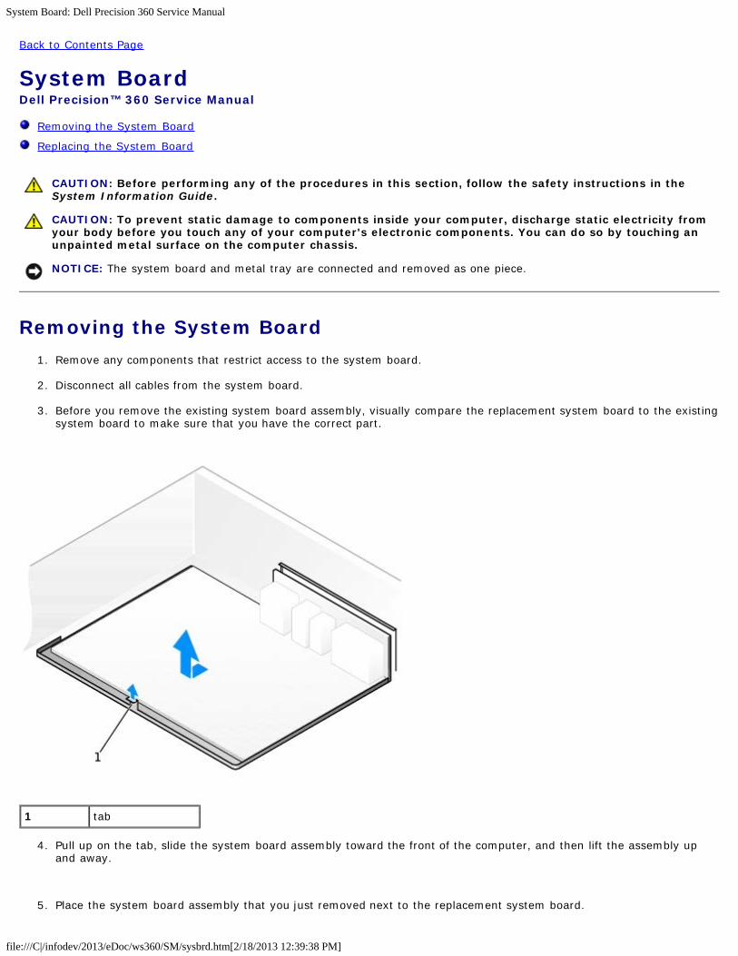
3. Before you remove the existing system board assembly, visually compare the replacement system board to the existingsystem board to make sure that you have the correct part.
1 tab
4. Pull up on the tab, slide the system board assembly toward the front of the computer, and then lift the assembly upand away.
5. Place the system board assembly that you just removed next to the replacement system board.
System Board: Dell Precision 360 Service Manual
file:///C|/infodev/2013/eDoc/ws360/SM/sysbrd.htm[2/18/2013 12:39:38 PM]
Replacing the System Board1. Transfer components from the existing system board to the replacement system board:
a. Remove the memory modules and install them on the replacement board.
CAUTION: The microprocessor package and heat-sink assembly can get hot. To avoid burns, ensure thatthe package and assembly have had sufficient time to cool before you touch them.
b. Remove the heat-sink assembly and microprocessor from the existing system board and transfer them to thereplacement system board.
2. Configure the settings of the replacement system board.
3. Set the jumpers on the replacement system board so they are identical to the ones on the existing board.
NOTE: Some components and connectors on the replacement system board may be in different locations than thecorresponding connectors on the existing system board.
4. Orient the replacement board by aligning the notches on the bottom of the board with the tabs on the computer.
5. Slide the system board assembly toward the back of the computer until the assembly clicks into position.
6. Replace any components and cables that you removed from the system board.
Back to Contents Page