Embed Size (px)
Citation preview
Dell PowerEdge FN I/O Module Getting Started Guide
Regulatory Model: FN I/O Module
Notes, cautions, and warningsNOTE: A NOTE indicates important information that helps you make better use of your computer.
CAUTION: A CAUTION indicates either potential damage to hardware or loss of data and tells you how to avoid the problem.
WARNING: A WARNING indicates a potential for property damage, personal injury, or death.
Copyright © 2015 Dell Inc. All rights reserved. This product is protected by U.S. and international copyright and intellectual property laws. Dell™ and the Dell logo are trademarks of Dell Inc. in the United States and/or other jurisdictions. All other marks and names mentioned herein may be trademarks of their respective companies.
2016 - 01
Rev. A01
1About this GuideThis document helps you in getting started with Dell PowerEdge FN I/O Module. For complete installation and configuration information, refer to the following documents:
Table 1. Dell PowerEdge FN I/O Module Documents
Information Documentation
Hardware installation and power-up instructions Installing the Dell PowerEdge FN I/O Module
Software configuration Dell PowerEdge FN I/O Module Configuration Guide
Command line interface Dell PowerEdge FN I/O Module Command Line Reference Guide
Latest updates Dell Networking OS Release Notes for the Dell PowerEdge FN I/O Module
About this Guide 3
2IntroductionThis document provides basic information about the Dell PowerEdge FN I/O Module, including how to install and perform the initial configuration. This document assumes the Dell PowerEdge FX2 server chassis is installed correctly. For complete installation instructions, see the Dell PowerEdge FN I/O Module Installation Guide.
For information about how to bring up, configure, and monitor the switch features, see the Dell PowerEdge FN I/O Module Configuration Guide, which is available on the Dell Support website at http://www.dell.com/support/manuals.
Product DescriptionThe FN I/O Module is a Layer 2/Layer 3, 12x10-Gigabit Ethernet switch that operates in a Dell PowerEdge FX2 server chassis. The chassis supports up to eight servers and two FN I/O modules with four uplink interfaces each. The FN I/O Module operates in Layer 2 I/O Aggregation mode or Layer 2/Layer 3 switch mode.
The Dell PowerEdge FX2 server chassis is managed by a single chassis management controller (CMC), which is similar to the CMC unit on the Dell PowerEdge M1000e and provides management connectivity to two FN I/O modules and the iDRAC units of all eight servers.
NOTE: By default, the FN I/O Module is in standalone mode. You can change the mode into Full Switch mode using the stack-unit stack-unit-id iom-mode full-switch command. For more information, see the Dell PowerEdge FN I/O Module Command Line Reference Guide.
4 Introduction
3Hardware OverviewThis section contains information about FN input/output module (IOM) characteristics and modular hardware configurations.
Internal Ports
The FN I/O Module provides 8x10 Gigabit Ethernet internal ports. The internal ports are connected to a server through the Dell PowerEdge FX2 server chassis midplane. It also provides an internal Ethernet interface — the out-of-band (OOB) interface, which is dedicated to switch management traffic on this port. The OOB interface is segregated from operational network traffic on the switch ports and cannot be switched or routed to the operational network.
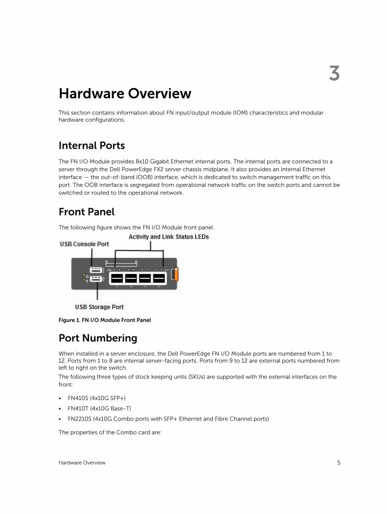
Front PanelThe following figure shows the FN I/O Module front panel.
Figure 1. FN I/O Module Front Panel
Port NumberingWhen installed in a server enclosure, the Dell PowerEdge FN I/O Module ports are numbered from 1 to 12. Ports from 1 to 8 are internal server-facing ports. Ports from 9 to 12 are external ports numbered from left to right on the switch.
The following three types of stock keeping units (SKUs) are supported with the external interfaces on the front:
• FN410S (4x10G SFP+)
• FN410T (4x10G Base-T)
• FN2210S (4x10G Combo ports with SFP+ Ethernet and Fibre Channel ports)
The properties of the Combo card are:
Hardware Overview 5
• Ports 9 and 10 are Fibre Channel (FC) type and support eight Gigabit FC, by default.
• Ports 11 and 12 are Ethernet type and support 10 Gigabit Ethernet, by default.
• You can also convert ports 9 and 10 to Ethernet type by using the port mode command.
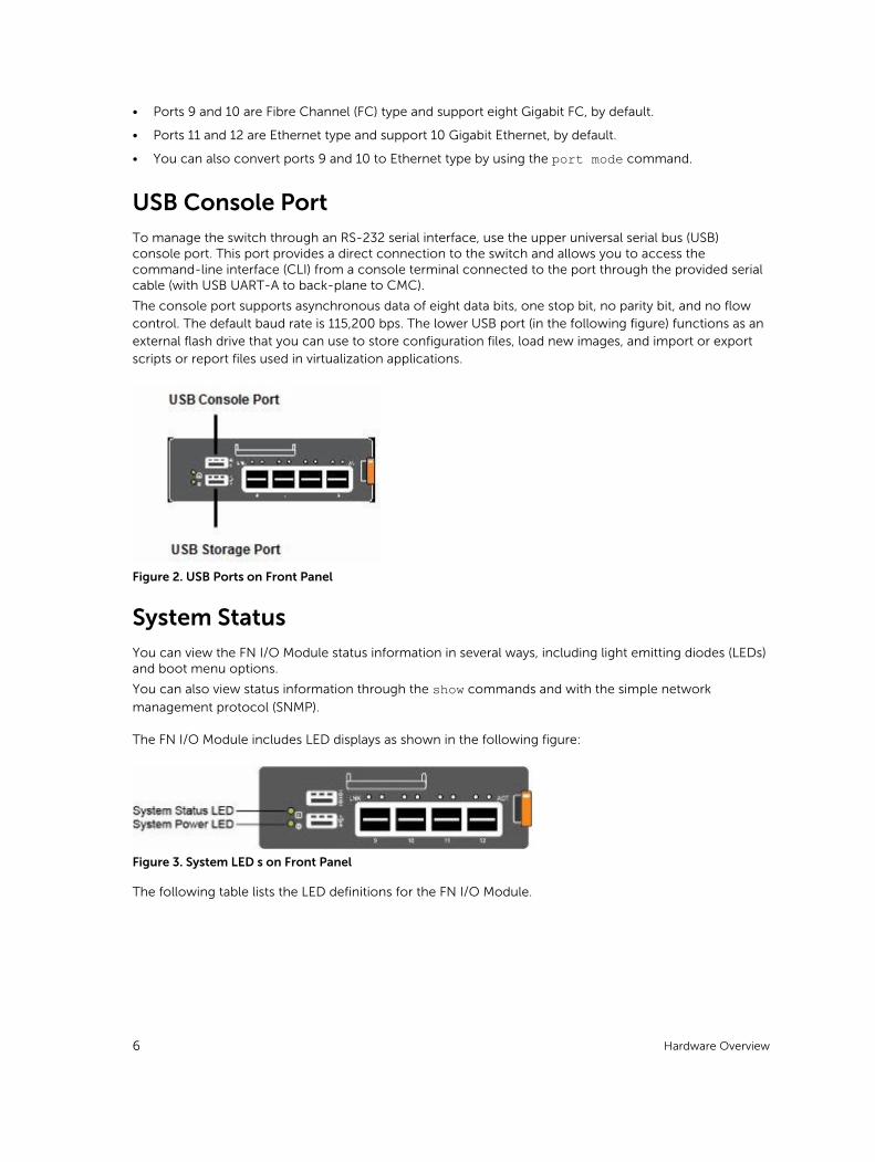
USB Console PortTo manage the switch through an RS-232 serial interface, use the upper universal serial bus (USB) console port. This port provides a direct connection to the switch and allows you to access the command-line interface (CLI) from a console terminal connected to the port through the provided serial cable (with USB UART-A to back-plane to CMC).
The console port supports asynchronous data of eight data bits, one stop bit, no parity bit, and no flow control. The default baud rate is 115,200 bps. The lower USB port (in the following figure) functions as an external flash drive that you can use to store configuration files, load new images, and import or export scripts or report files used in virtualization applications.
Figure 2. USB Ports on Front Panel
System StatusYou can view the FN I/O Module status information in several ways, including light emitting diodes (LEDs) and boot menu options.
You can also view status information through the show commands and with the simple network
management protocol (SNMP).
The FN I/O Module includes LED displays as shown in the following figure:
Figure 3. System LED s on Front Panel
The following table lists the LED definitions for the FN I/O Module.
6 Hardware Overview
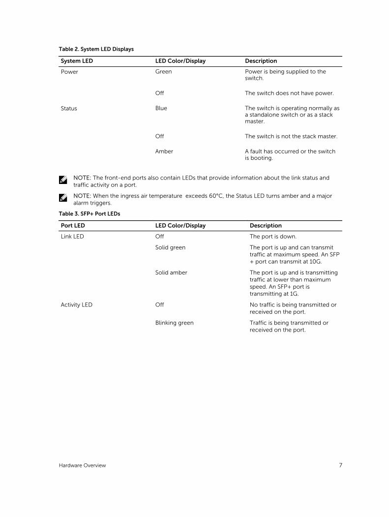
Table 2. System LED Displays
System LED LED Color/Display Description
Power Green Power is being supplied to the switch.
Off The switch does not have power.
Status Blue The switch is operating normally as a standalone switch or as a stack master.
Off The switch is not the stack master.
Amber A fault has occurred or the switch is booting.
NOTE: The front-end ports also contain LEDs that provide information about the link status and traffic activity on a port.
NOTE: When the ingress air temperature exceeds 60°C, the Status LED turns amber and a major alarm triggers.
Table 3. SFP+ Port LEDs
Port LED LED Color/Display Description
Link LED Off The port is down.
Solid green The port is up and can transmit traffic at maximum speed. An SFP+ port can transmit at 10G.
Solid amber The port is up and is transmitting traffic at lower than maximum speed. An SFP+ port is transmitting at 1G.
Activity LED Off No traffic is being transmitted or received on the port.
Blinking green Traffic is being transmitted or received on the port.
Hardware Overview 7
4InstallationThis switch installation procedure assumes that the Dell PowerEdge FX2 server chassis is installed correctly. For complete installation instructions, refer to the Dell PowerEdge FX2 server chassis Installation Guide.
• AC/DC power cord — The cord reaches from the power outlet to the Utility-panel connector.
• Cabling — The cabling is routed to avoid sources of electrical noise such as radio transmitters, broadcast amplifiers, power lines, and fluorescent lighting fixtures.
• Airflow — The airflow around the switch and through the vents is unrestricted.
Unpacking the FN I/O Module
When unpacking the FN I/O Module, ensure that the following items are included:
• One FN I/O Module
• One USB type A-to-DB-9 female cable
• Getting Started Guide
• Safety and Regulatory Information
• Warranty and Support Information
• Software License Agreement
Unpacking StepsNOTE: Before unpacking the FN I/O Module, inspect the container and immediately report any evidence of damage.
1. Place the container on a clean, flat surface and cut all straps securing the container.
2. Open the container or remove the container top.
3. Carefully remove the switch from the container and place it on a secure and clean surface.
4. Remove all packing material.
5. Inspect the product and accessories for damage.
8 Installation
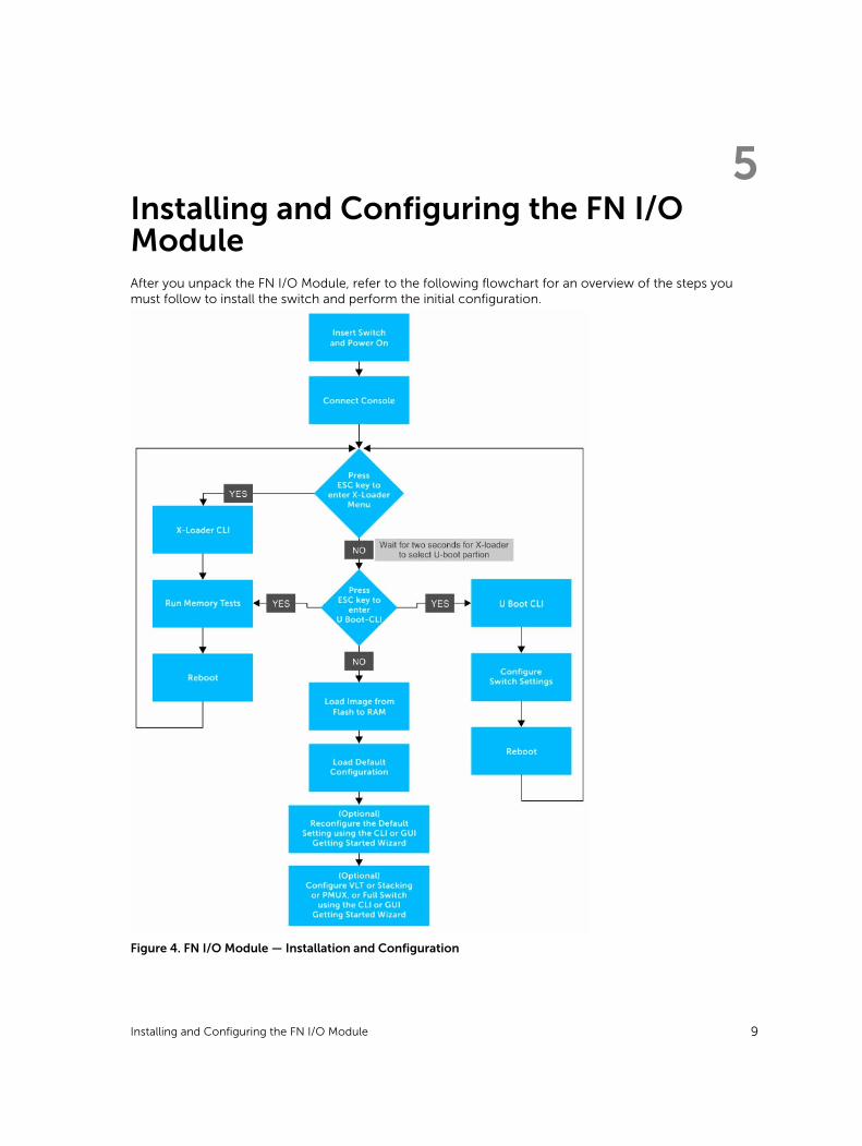
5Installing and Configuring the FN I/O ModuleAfter you unpack the FN I/O Module, refer to the following flowchart for an overview of the steps you must follow to install the switch and perform the initial configuration.
Figure 4. FN I/O Module — Installation and Configuration
Installing and Configuring the FN I/O Module 9
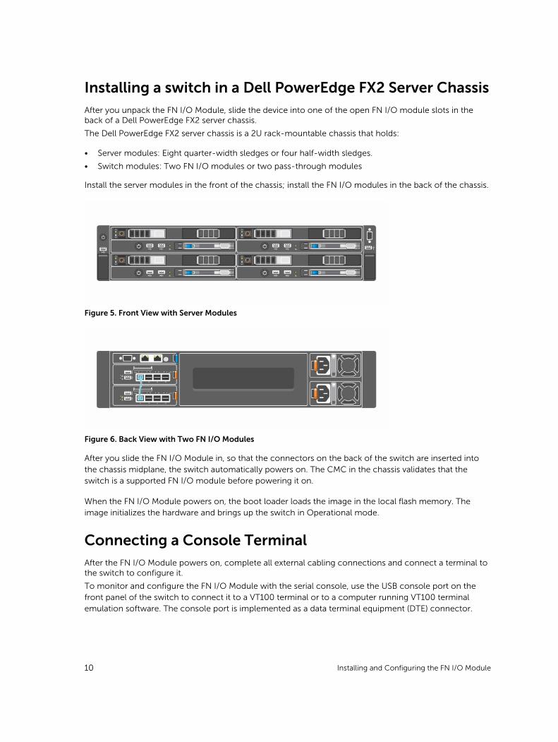
Installing a switch in a Dell PowerEdge FX2 Server ChassisAfter you unpack the FN I/O Module, slide the device into one of the open FN I/O module slots in the back of a Dell PowerEdge FX2 server chassis.
The Dell PowerEdge FX2 server chassis is a 2U rack-mountable chassis that holds:
• Server modules: Eight quarter-width sledges or four half-width sledges.
• Switch modules: Two FN I/O modules or two pass-through modules
Install the server modules in the front of the chassis; install the FN I/O modules in the back of the chassis.
Figure 5. Front View with Server Modules
Figure 6. Back View with Two FN I/O Modules
After you slide the FN I/O Module in, so that the connectors on the back of the switch are inserted into the chassis midplane, the switch automatically powers on. The CMC in the chassis validates that the switch is a supported FN I/O module before powering it on.
When the FN I/O Module powers on, the boot loader loads the image in the local flash memory. The image initializes the hardware and brings up the switch in Operational mode.
Connecting a Console TerminalAfter the FN I/O Module powers on, complete all external cabling connections and connect a terminal to the switch to configure it.
To monitor and configure the FN I/O Module with the serial console, use the USB console port on the front panel of the switch to connect it to a VT100 terminal or to a computer running VT100 terminal emulation software. The console port is implemented as a data terminal equipment (DTE) connector.
10 Installing and Configuring the FN I/O Module
To use the console port, you need the following equipment:
• VT100-compatible terminal, a desktop, or a portable computer with a serial port running VT100 terminal emulation software, such as Microsoft HyperTerminal.
• A serial cable (provided) with a USB type-A connector for the console port and DB-9 connector for the terminal.
To connect a terminal to the switch console port, perform the following tasks:
1. Connect the DB-9 connector on the serial cable to the terminal or computer running VT100 terminal emulation software.
2. Configure the terminal emulation software as follows:
a. Select the appropriate serial port (for example, COM 1) to connect to the console.
b. Set the data rate to 115200 baud.
c. Set the data format to 8 data bits, 1 stop bit, and no parity.
d. Set the flow control to none.
e. Set the terminal emulation mode to VT100.
f. Select Terminal keys for Function, Arrow, and Ctrl keys. Ensure that the setting is for Terminal keys (not Microsoft Windows keys).
The default enable password is calvin.
3. Connect the USB connector on the cable directly to the switch console port. The console port is located on the left side of the front-end ports.
Invoking the X-Loader and U-Boot CLIsDuring the boot process, you can perform various configuration tasks by accessing the X-Loader and U-Boot CLIs, such as running memory tests (X-Loader) and activating the backup image or recovering a password (U-Boot).
You are first prompted to enter the X-Loader CLI by pressing the ESC key when the following message displays:
Hit ESC key to stop autoboot
If you do not press a key, the boot process continues and you are prompted to enter the U-Boot CLI by pressing any key.
After performing any of the X-Loader or U-Boot tasks, the switch automatically reboots when you exit the CLI. To continue with the boot process without entering either CLI, do not press ESC key.
Installing and Configuring the FN I/O Module 11
6Next StepsYou can customize the FN I/O Module for use in your data center network. To perform additional switch configuration, do one of the following:
• For remote OOB management, enter the OOB management interface IP address into a Telnet or secure shell (SSH) client and log in to the switch using the user ID and password to access the CLI. The default user ID is root and the default password is calvin.
• For local management using the CLI, use the attached console connection.
• For remote in-band management from a network management station, enter the IP address of the default virtual local area network (VLAN) and log in to the switch to access the CLI.
• In a Dell Networking OS upgrade, ensure that the FN I/O Module is running the latest Dell Networking OS version by entering the show version command.
For information about how to configure the software features, see the Dell PowerEdge FN I/O Module Configuration Guide, which is available on the Dell Support website at http://www.dell.com/support/manuals.
For information about how to configure the Dell PowerEdge FN I/O Module using Graphical User Interface (GUI), see the Dell Blade I/O Manager Online Help.
12 Next Steps
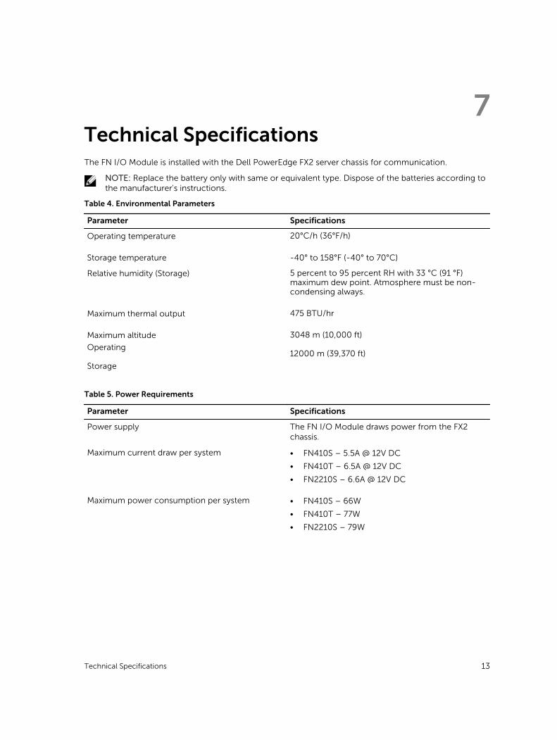
7Technical SpecificationsThe FN I/O Module is installed with the Dell PowerEdge FX2 server chassis for communication.
NOTE: Replace the battery only with same or equivalent type. Dispose of the batteries according to the manufacturer's instructions.
Table 4. Environmental Parameters
Parameter Specifications
Operating temperature 20°C/h (36°F/h)
Storage temperature -40° to 158°F (-40° to 70°C)
Relative humidity (Storage) 5 percent to 95 percent RH with 33 °C (91 °F) maximum dew point. Atmosphere must be non-condensing always.
Maximum thermal output 475 BTU/hr
Maximum altitude
Operating
Storage
3048 m (10,000 ft)
12000 m (39,370 ft)
Table 5. Power Requirements
Parameter Specifications
Power supply The FN I/O Module draws power from the FX2 chassis.
Maximum current draw per system • FN410S – 5.5A @ 12V DC
• FN410T – 6.5A @ 12V DC
• FN2210S – 6.6A @ 12V DC
Maximum power consumption per system • FN410S – 66W
• FN410T – 77W
• FN2210S – 79W
Technical Specifications 13