Embed Size (px)
Citation preview

Dell PowerEdge FN I/O AggregatorCommand Line Reference Guide
9.8(0.0)

Notes, cautions, and warningsNOTE: A NOTE indicates important information that helps you make better use of your computer.
CAUTION: A CAUTION indicates either potential damage to hardware or loss of data and tells you how to avoid the problem.
WARNING: A WARNING indicates a potential for property damage, personal injury, or death.
Copyright © 2015 Dell Inc. All rights reserved. This product is protected by U.S. and international copyright and intellectual property laws. Dell™
and the Dell logo are trademarks of Dell Inc. in the United States and/or other jurisdictions. All other marks and names mentioned herein may be trademarks of their respective companies.
2015–05
Rev. A03

Contents
1 About this Guide.............................................................................................................14Objectives......................................................................................................................................................................... 14Audience........................................................................................................................................................................... 14Conventions...................................................................................................................................................................... 14Information Icons.............................................................................................................................................................. 15
2 Before You Start............................................................................................................ 16Operational Modes............................................................................................................................................................16Default Settings................................................................................................................................................................ 16Other Auto-Configured Settings....................................................................................................................................... 17DCB Support.....................................................................................................................................................................17FCoE Connectivity............................................................................................................................................................ 17iSCSI Operation.................................................................................................................................................................18Link Aggregation............................................................................................................................................................... 18Link Tracking..................................................................................................................................................................... 18VLANs...............................................................................................................................................................................18Where to Go From Here....................................................................................................................................................19
3 CLI Basics..................................................................................................................... 20Accessing the Command Line.......................................................................................................................................... 20Multiple Configuration Users............................................................................................................................................ 20Navigating the CLI............................................................................................................................................................ 21Obtaining Help.................................................................................................................................................................. 21Using the Keyword no Command..................................................................................................................................... 23Filtering show Commands................................................................................................................................................ 23Command Modes............................................................................................................................................................. 24Track Login Activity.......................................................................................................................................................... 26
Restrictions for Tracking Login Activity.......................................................................................................................26Configuring Login Activity Tracking............................................................................................................................ 26Display Login Statistics............................................................................................................................................... 26
Limit Concurrent Login Sessions.......................................................................................................................................27
Restrictions for Limiting the Number of Concurrent Sessions.................................................................................... 27Configuring Concurrent Session Limit.........................................................................................................................27Enabling the System to Clear Existing Sessions..........................................................................................................28
4 File Management...........................................................................................................29boot system gateway....................................................................................................................................................... 29boot system stack-unit.....................................................................................................................................................29cd.....................................................................................................................................................................................30copy................................................................................................................................................................................. 30copy running-config startup-config..................................................................................................................................32delete............................................................................................................................................................................... 32
3

dir.....................................................................................................................................................................................33format flash......................................................................................................................................................................33HTTP Copy via CLI...........................................................................................................................................................34logging coredump stack-unit............................................................................................................................................ 35pwd..................................................................................................................................................................................35rename............................................................................................................................................................................. 35restore factory-defaults....................................................................................................................................................36show boot system............................................................................................................................................................ 37show file...........................................................................................................................................................................38show file-systems.............................................................................................................................................................39show os-version............................................................................................................................................................... 40show running-config........................................................................................................................................................ 40show version.................................................................................................................................................................... 42upgrade boot....................................................................................................................................................................43upgrade system................................................................................................................................................................44
5 Control and Monitoring................................................................................................. 46asset-tag.......................................................................................................................................................................... 46clear alarms...................................................................................................................................................................... 46clear command history..................................................................................................................................................... 47configure.......................................................................................................................................................................... 47debug cpu-traffic-stats.................................................................................................................................................... 48debug ifm trace-flags....................................................................................................................................................... 48disable.............................................................................................................................................................................. 49enable...............................................................................................................................................................................49end...................................................................................................................................................................................50exit...................................................................................................................................................................................50ftp-server enable............................................................................................................................................................. 50ftp-server topdir............................................................................................................................................................... 51ftp-server username........................................................................................................................................................ 52hostname......................................................................................................................................................................... 52ip telnet server enable...................................................................................................................................................... 53ip telnet source-interface................................................................................................................................................. 53line................................................................................................................................................................................... 54ping.................................................................................................................................................................................. 54reload............................................................................................................................................................................... 55service timestamps.......................................................................................................................................................... 55show alarms..................................................................................................................................................................... 56show command-history.................................................................................................................................................... 57show configuration lock....................................................................................................................................................58show cpu-traffic-stats......................................................................................................................................................59show debugging...............................................................................................................................................................59show diag.........................................................................................................................................................................60show environment............................................................................................................................................................60show inventory..................................................................................................................................................................61show memory...................................................................................................................................................................62
4
show processes cpu.........................................................................................................................................................63show processes ipc flow-control...................................................................................................................................... 65show processes memory..................................................................................................................................................66show revision....................................................................................................................................................................68show server-interfaces.....................................................................................................................................................69show system.................................................................................................................................................................... 70show tech-support............................................................................................................................................................71show uplink brief...............................................................................................................................................................74show util-threshold cpu.................................................................................................................................................... 75show util-threshold memory............................................................................................................................................. 75ssh-peer-stack-unit.......................................................................................................................................................... 76telnet................................................................................................................................................................................76telnet-peer-stack-unit.......................................................................................................................................................77terminal length..................................................................................................................................................................77terminal monitor............................................................................................................................................................... 78terminal xml...................................................................................................................................................................... 78trace route........................................................................................................................................................................79undebug all.......................................................................................................................................................................80write.................................................................................................................................................................................80
6 u-Boot........................................................................................................................... 81boot change......................................................................................................................................................................81boot show net config retries............................................................................................................................................. 81boot write net config retries............................................................................................................................................. 82boot zero..........................................................................................................................................................................82default gateway................................................................................................................................................................82enable...............................................................................................................................................................................83help.................................................................................................................................................................................. 83ignore enable password.................................................................................................................................................... 84ignore startup-config........................................................................................................................................................84interface management ethernet ip address...................................................................................................................... 84no default gateway...........................................................................................................................................................85no interface management ethernet ip address................................................................................................................. 85reload............................................................................................................................................................................... 85show boot blc...................................................................................................................................................................86show boot selection......................................................................................................................................................... 86show bootflash................................................................................................................................................................. 87show bootvar....................................................................................................................................................................87show default gateway...................................................................................................................................................... 88show interface management ethernet..............................................................................................................................88show interface management port config..........................................................................................................................89syntax help....................................................................................................................................................................... 89
7 Data Center Bridging (DCB)..........................................................................................90advertise dcbx-appln-tlv...................................................................................................................................................90advertise dcbx-tlv............................................................................................................................................................. 91
5

bandwidth-percentage..................................................................................................................................................... 92clear dcbx counters.......................................................................................................................................................... 92clear ets counters.............................................................................................................................................................93clear pfc counters.............................................................................................................................................................93dcb-enable....................................................................................................................................................................... 94dcb enable pfc-queues..................................................................................................................................................... 94dcb enable auto-detect on-next-reload............................................................................................................................95dcb-map stack-unit all stack-ports all............................................................................................................................... 97dcbx-port role...................................................................................................................................................................98dcbx version.....................................................................................................................................................................99debug dcbx...................................................................................................................................................................... 99fc-map............................................................................................................................................................................100fcoe-map.........................................................................................................................................................................101fcoe priority-bits............................................................................................................................................................. 102iscsi priority-bits..............................................................................................................................................................102keepalive......................................................................................................................................................................... 102interface vlan (NPIV proxy gateway)...............................................................................................................................103pfc mode on................................................................................................................................................................... 104pfc no-drop queues........................................................................................................................................................ 104priority-group bandwidth pfc.......................................................................................................................................... 105priority-pgid.................................................................................................................................................................... 106qos-policy-output ets...................................................................................................................................................... 107scheduler........................................................................................................................................................................ 108show dcb........................................................................................................................................................................ 109show interface dcbx detail.............................................................................................................................................. 109show interface ets........................................................................................................................................................... 112show interface pfc...........................................................................................................................................................115show interface pfc statistics............................................................................................................................................ 117show qos dcb-map.......................................................................................................................................................... 118show stack-unit stack-ports ets details........................................................................................................................... 119show stack-unit stack-ports pfc details.......................................................................................................................... 120
8 Dynamic Host Configuration Protocol.......................................................................... 122clear ip dhcp client statistics........................................................................................................................................... 122debug ip dhcp client events............................................................................................................................................ 123debug ip dhcp client packets...........................................................................................................................................123ip address dhcp...............................................................................................................................................................124release dhcp interface..................................................................................................................................................... 124renew dhcp interface...................................................................................................................................................... 125show ip dhcp client statistics.......................................................................................................................................... 126show ip dhcp lease..........................................................................................................................................................126
9 FIP Snooping............................................................................................................... 127clear fip-snooping database interface vlan...................................................................................................................... 127
clear fip-snooping statistics.......................................................................................................................................127feature fip-snooping..................................................................................................................................................128
6

fip-snooping enable...................................................................................................................................................128fip-snooping fc-map................................................................................................................................................. 129fip-snooping port-mode fcf.......................................................................................................................................129
show fip-snooping statistics........................................................................................................................................... 130debug fip-snooping......................................................................................................................................................... 132show fip-snooping config................................................................................................................................................133show fip-snooping enode................................................................................................................................................134show fip-snooping fcf..................................................................................................................................................... 135show fip-snooping sessions............................................................................................................................................ 135show fip-snooping statistics........................................................................................................................................... 136show fip-snooping system.............................................................................................................................................. 139show fip-snooping vlan................................................................................................................................................... 140
10 Internet Group Management Protocol (IGMP)............................................................ 141IGMP Commands............................................................................................................................................................ 141IGMP Snooping Commands............................................................................................................................................ 142clear ip igmp groups........................................................................................................................................................ 142debug ip igmp................................................................................................................................................................. 142ip igmp group-join-limit....................................................................................................................................................143ip igmp querier-timeout................................................................................................................................................... 143ip igmp query-interval......................................................................................................................................................144ip igmp query-max-resp-time.......................................................................................................................................... 144ip igmp snooping enable..................................................................................................................................................145ip igmp snooping fast-leave............................................................................................................................................ 145ip igmp snooping flood.................................................................................................................................................... 146ip igmp snooping last-member-query-interval................................................................................................................. 146ip igmp snooping mrouter................................................................................................................................................147ip igmp snooping querier................................................................................................................................................. 147ip igmp version................................................................................................................................................................148show ip igmp groups....................................................................................................................................................... 148show ip igmp interface.................................................................................................................................................... 149show ip igmp snooping mrouter...................................................................................................................................... 150
11 Interfaces.................................................................................................................... 151Port Interface Commands................................................................................................................................................151Port Channel Commands.................................................................................................................................................151Time Domain Reflectometer (TDR) Commands.............................................................................................................. 152Virtual LAN (VLAN) Commands..................................................................................................................................... 152auto vlan......................................................................................................................................................................... 152channel-member.............................................................................................................................................................153clear counters................................................................................................................................................................. 154clear mac-address-table dynamic................................................................................................................................... 154default vlan-id.................................................................................................................................................................155description......................................................................................................................................................................155feature fc........................................................................................................................................................................156flowcontrol......................................................................................................................................................................156
7

interface......................................................................................................................................................................... 158interface ManagementEthernet......................................................................................................................................159interface port-channel.................................................................................................................................................... 160interface range................................................................................................................................................................ 161interface vlan.................................................................................................................................................................. 162intf-type cr4 autoneg...................................................................................................................................................... 163keepalive......................................................................................................................................................................... 164minimum-links................................................................................................................................................................. 164monitor interface............................................................................................................................................................ 165mtu................................................................................................................................................................................. 167name...............................................................................................................................................................................168negotiation auto..............................................................................................................................................................169show config (INTERFACE mode)....................................................................................................................................170show config (from INTERFACE RANGE mode).............................................................................................................. 170show config (from INTERFACE VLAN mode).................................................................................................................. 171show config (from PROTOCOL LLDP mode).................................................................................................................. 171show interfaces...............................................................................................................................................................172show interfaces configured............................................................................................................................................. 175show interfaces description............................................................................................................................................ 175show interfaces port-channel..........................................................................................................................................176show interfaces stack-unit.............................................................................................................................................. 179show interfaces status....................................................................................................................................................180show interfaces switchport..............................................................................................................................................181show tdr......................................................................................................................................................................... 182show vlan........................................................................................................................................................................183shutdown........................................................................................................................................................................184speed (for 1000/10000 interfaces)................................................................................................................................. 185stack-unit port-group port mode ethernet...................................................................................................................... 186tdr-cable-test..................................................................................................................................................................186vlan tagged (CMC)......................................................................................................................................................... 187vlan untagged (CMC)..................................................................................................................................................... 188
12 IPv4 Routing.............................................................................................................. 190clear tcp statistics...........................................................................................................................................................190debug ip dhcp................................................................................................................................................................. 190debug ip icmp.................................................................................................................................................................. 191ip route........................................................................................................................................................................... 192management route..........................................................................................................................................................193show arp.........................................................................................................................................................................194show ip interface............................................................................................................................................................ 195show ip management-route.............................................................................................................................................197show ip multicast-cam stack-unit....................................................................................................................................197show ip route.................................................................................................................................................................. 199show tcp statistics.........................................................................................................................................................200
13 iSCSI Optimization.....................................................................................................203
8

advertise dcbx-app-tlv................................................................................................................................................... 203iscsi aging time...............................................................................................................................................................203iscsi cos......................................................................................................................................................................... 204iscsi enable.....................................................................................................................................................................205iscsi priority-bits.............................................................................................................................................................205iscsi profile-compellent...................................................................................................................................................206iscsi target port..............................................................................................................................................................206show iscsi.......................................................................................................................................................................207show iscsi sessions.........................................................................................................................................................207show iscsi sessions detailed........................................................................................................................................... 208
14 Isolated Networks.......................................................................................................210io-aggregator isolated-network vlan................................................................................................................................210show io-aggregator isolated-networks ...........................................................................................................................210
15 Link Aggregation Control Protocol (LACP)................................................................. 212auto-lag enable............................................................................................................................................................... 212clear lacp counters..........................................................................................................................................................212debug lacp...................................................................................................................................................................... 213io-aggregator auto-lag enable......................................................................................................................................... 213lacp link-fallback member................................................................................................................................................214lacp long-timeout............................................................................................................................................................ 214lacp port-priority............................................................................................................................................................. 215port-channel mode......................................................................................................................................................... 215port-channel-protocol lacp..............................................................................................................................................216show interfaces port-channel..........................................................................................................................................217show io-aggregator auto-lag status................................................................................................................................ 219show lacp.......................................................................................................................................................................220show link-bundle-distribution port-channel..................................................................................................................... 221show port-channel-flow................................................................................................................................................. 222
16 Layer 2.......................................................................................................................224MAC Addressing Commands..........................................................................................................................................224Virtual LAN (VLAN) Commands.....................................................................................................................................224clear mac-address-table dynamic...................................................................................................................................224description..................................................................................................................................................................... 225mac-address-table aging-time........................................................................................................................................225mac-address-table static................................................................................................................................................226mac-address-table station-move refresh-arp................................................................................................................. 226show cam mac stack-unit...............................................................................................................................................227show mac-address-table................................................................................................................................................ 228
17 Link Layer Discovery Protocol (LLDP)........................................................................ 231advertise dot3-tlv............................................................................................................................................................231advertise management-tlv..............................................................................................................................................232clear lldp counters.......................................................................................................................................................... 232
9

clear lldp neighbors.........................................................................................................................................................233debug lldp interface........................................................................................................................................................233disable............................................................................................................................................................................234hello............................................................................................................................................................................... 234multiplier........................................................................................................................................................................ 235protocol lldp (Configuration)...........................................................................................................................................235protocol lldp (Interface)..................................................................................................................................................236show lldp neighbors........................................................................................................................................................236show lldp statistics......................................................................................................................................................... 237
18 NPIV Proxy Gateway..................................................................................................238dcb-map.........................................................................................................................................................................238description (for FCoE maps).......................................................................................................................................... 239fabric-id vlan.................................................................................................................................................................. 239fcf-priority......................................................................................................................................................................240fc-map............................................................................................................................................................................ 241fcoe-map........................................................................................................................................................................ 241feature fc....................................................................................................................................................................... 243fka-adv-period............................................................................................................................................................... 243keepalive........................................................................................................................................................................ 244show fcoe-map.............................................................................................................................................................. 244show fc sw.....................................................................................................................................................................246show interfaces status................................................................................................................................................... 247show npiv devices.......................................................................................................................................................... 247show qos dcb-map........................................................................................................................................................ 250show running-config fcoe-map....................................................................................................................................... 251
19 Port Monitoring......................................................................................................... 252description..................................................................................................................................................................... 252monitor session.............................................................................................................................................................. 253show config................................................................................................................................................................... 254show monitor session.....................................................................................................................................................254show running-config monitor session.............................................................................................................................255source (port monitoring)................................................................................................................................................255
20 Quality of Service (QoS)........................................................................................... 257Per-Port QoS Commands...............................................................................................................................................257Policy-Based QoS Commands........................................................................................................................................257bandwidth-percentage................................................................................................................................................... 257description..................................................................................................................................................................... 258dot1p-priority................................................................................................................................................................. 258policy-aggregate............................................................................................................................................................ 259policy-map-output......................................................................................................................................................... 260qos-policy-output........................................................................................................................................................... 261rate-shape...................................................................................................................................................................... 261service-class bandwidth-percentage..............................................................................................................................262
10

service-class dot1p-mapping..........................................................................................................................................262service-class dynamic dot1p...........................................................................................................................................263service-policy output......................................................................................................................................................264service-queue................................................................................................................................................................ 265show qos dcb-map........................................................................................................................................................ 266show qos dot1p-queue-mapping.................................................................................................................................... 267show qos qos-policy-output........................................................................................................................................... 267trust...............................................................................................................................................................................268
21 Security..................................................................................................................... 269AAA Accounting Commands..........................................................................................................................................269
aaa accounting.........................................................................................................................................................269aaa accounting suppress.......................................................................................................................................... 270aaa authorization commands.....................................................................................................................................271aaa authorization config-commands......................................................................................................................... 271aaa authorization exec..............................................................................................................................................272accounting................................................................................................................................................................272show accounting...................................................................................................................................................... 273
Authentication and Password Commands...................................................................................................................... 273aaa authentication enable.........................................................................................................................................273aaa authentication login............................................................................................................................................275banner exec..............................................................................................................................................................276banner login..............................................................................................................................................................277banner motd.............................................................................................................................................................278debug radius.............................................................................................................................................................278debug tacacs+......................................................................................................................................................... 279exec-banner............................................................................................................................................................. 279ip radius source-interface.........................................................................................................................................280ip tacacs source-interface........................................................................................................................................280login authentication...................................................................................................................................................281
RADIUS Commands........................................................................................................................................................281radius-server deadtime............................................................................................................................................. 281radius-server host.................................................................................................................................................... 282radius-server key......................................................................................................................................................283radius-server retransmit........................................................................................................................................... 284radius-server timeout............................................................................................................................................... 284show privilege.......................................................................................................................................................... 285
Suppressing AAA Accounting for Null Username Sessions.............................................................................................285TACACS+ Commands....................................................................................................................................................285
TACACS+ Accounting.............................................................................................................................................. 285tacacs-server host................................................................................................................................................... 287tacacs-server key.....................................................................................................................................................287timeout login response............................................................................................................................................. 288
SSH Server and SCP Commands...................................................................................................................................289enable password...................................................................................................................................................... 289enable restricted...................................................................................................................................................... 290
11

service password-encryption................................................................................................................................... 290show ip ssh...............................................................................................................................................................291show ip ssh client-pub-keys......................................................................................................................................291show ip ssh rsa-authentication.................................................................................................................................292show users...............................................................................................................................................................292ssh........................................................................................................................................................................... 293username................................................................................................................................................................. 293
22 Stacking Commands................................................................................................. 295power-cycle stack-unit...................................................................................................................................................295reset stack-unit..............................................................................................................................................................296show system stack-ports............................................................................................................................................... 297show system stack-unit iom-mode.................................................................................................................................298show system stack-unit stack-group..............................................................................................................................299stack-unit iom-mode......................................................................................................................................................299stack-unit priority...........................................................................................................................................................300stack-unit renumber........................................................................................................................................................301
23 Storm Control........................................................................................................... 302io-aggregator broadcast storm-control.......................................................................................................................... 302show io-aggregator broadcast storm-control status...................................................................................................... 303show storm-control unknown-unicast............................................................................................................................303storm-control broadcast (Interface)...............................................................................................................................304storm-control multicast (Interface)................................................................................................................................ 304storm-control unknown-unicast (Interface)................................................................................................................... 305
24 System Time............................................................................................................. 306calendar set................................................................................................................................................................... 306clock read-calendar........................................................................................................................................................ 307clock set.........................................................................................................................................................................307clock summer-time date.................................................................................................................................................308clock summer-time recurring..........................................................................................................................................309clock timezone................................................................................................................................................................310clock update-calendar......................................................................................................................................................311ntp server........................................................................................................................................................................ 311show calendar.................................................................................................................................................................312show clock......................................................................................................................................................................312
25 Uplink Failure Detection (UFD).................................................................................. 314clear ufd-disable..............................................................................................................................................................314debug uplink-state-group................................................................................................................................................315defer-timer......................................................................................................................................................................315description...................................................................................................................................................................... 316downstream....................................................................................................................................................................316downstream auto-recover...............................................................................................................................................317downstream disable links.................................................................................................................................................317
12

enable............................................................................................................................................................................. 318show running-config uplink-state-group......................................................................................................................... 318show uplink-state-group................................................................................................................................................. 319uplink-state-group..........................................................................................................................................................320upstream.........................................................................................................................................................................321
26 Virtual Link Trunking (VLT)........................................................................................323back-up destination........................................................................................................................................................323clear vlt statistics........................................................................................................................................................... 324lacp ungroup member-independent................................................................................................................................324peer-link port-channel.................................................................................................................................................... 325show vlt backup-link...................................................................................................................................................... 326show vlt brief................................................................................................................................................................. 326show vlt detail................................................................................................................................................................ 327show vlt mismatch......................................................................................................................................................... 327show vlt role...................................................................................................................................................................328show vlt statistics.......................................................................................................................................................... 328stack-unit iom-mode......................................................................................................................................................330system-mac................................................................................................................................................................... 330unit-id............................................................................................................................................................................. 331vlt domain....................................................................................................................................................................... 331vlt-peer-lag port-channel............................................................................................................................................... 332
27 Debugging and Diagnostics....................................................................................... 333Offline Diagnostic Commands........................................................................................................................................ 333Hardware Commands.....................................................................................................................................................333clear hardware stack-unit...............................................................................................................................................334diag stack-unit............................................................................................................................................................... 334hardware watchdog....................................................................................................................................................... 335offline stack-unit............................................................................................................................................................ 336show diag.......................................................................................................................................................................336show hardware stack-unit..............................................................................................................................................339show hardware system-flow...........................................................................................................................................347show hardware buffer interface..................................................................................................................................... 349show hardware counters interface interface................................................................................................................... 351show hardware stack-unit buffer-stats-snapshot (Total Buffer Information).................................................................. 352show hardware buffer-stats-snapshot........................................................................................................................... 354show hardware drops..................................................................................................................................................... 357
A Internet Control Message Protocol (ICMP) Message Types........................................359
13

1About this GuideThis book provides information about the Dell Networking OS command line interface (CLI) on the Dell PowerEdge FN I/O Aggregator.
This book also includes information about the protocols and features found in the Dell Networking OS and on the Dell Networking systems supported by the Dell Networking OS.
ReferencesFor more information about your system, refer to the following documents:
• Dell PowerEdge FN I/O Aggregator Configuration Guide
• Dell PowerEdge FN I/O Aggregator Getting Started Guide
• Release Notes for the Dell PowerEdge FN I/O Aggregator
ObjectivesThis book is intended as a reference guide for the Aggregator CLI commands, with detailed syntax statements, along with usage information and sample output.
This guide contains an Appendix with a list of the request for comment (RFCs) and management information base files (MIBs) supported.
NOTE: For more information about when to use the CLI commands, refer to the Dell PowerEdge FN I/O Aggregator Configuration Guide for your system.
AudienceThis book is intended for system administrators who are responsible for configuring or maintaining networks. This guide assumes that you are knowledgeable in Layer 2 and Layer 3 networking technologies.
ConventionsThis book uses the following conventions to describe command syntax.
Keyword Keywords are in Courier font and must be entered in the CLI as listed.
parameter Parameters are in italics and require a number or word to be entered in the CLI.
{X} Keywords and parameters within braces must be entered in the CLI.
14

[X] Keywords and parameters within brackets are optional.
x|y Keywords and parameters separated by a bar require you to choose one option.
x||y Keywords and parameters separated by a double bar allows you to choose any or all of the options.
Information IconsThis book uses the following information symbols:
NOTE: The Note icon signals important operational information.
CAUTION: The Caution icon signals information about situations that could result in equipment damage or loss of data.
WARNING: The Warning icon signals information about hardware handling that could result in injury.
15

2Before You StartBy following the instructions in the Dell PowerEdge FN I/O Aggregator Getting Started Guide that is shipped with the product, you install the Aggregator in a Dell PowerEdge FX2 server chassis.
The Aggregator installs with zero-touch configuration. After you power it on, an Aggregator boots up with default settings and auto-configures with software features enabled. This chapter describes the default settings and software features that are automatically configured at startup. Use the tasks described in the other chapters to reconfigure the Aggregator for customized network operation.
Operational ModesThe I/O Aggregator supports four operational modes. Select the operational mode that meets your deployment needs. To enable a new operational mode, reload the switch.
• Standalone mode — stack-unit unit iom-mode standalone. This is the default mode for IOA. It is fully automated zero-touch mode that allows you to configure VLAN memberships. (Supported in CMC)
• Programmable MUX mode (PMUX) — stack-unit unit iom-mode programmable-mux. Select this mode to configure PMUX mode CLI commands.
• Stacking mode — stack-unit unit iom-mode stacking. Select this mode to stack up to 6 IOA stack units as a single logical switch. The stack units can be in the same or on different chassis. This is a low-touch mode where all configuration except VLAN membership is automated. To enable VLAN, you must configure it. In this operational mode, base module links are dedicated to stacking.
• Virtual Link Trunking mode (VLT) — stack-unit unit iom-mode vlt. Select this mode to multi-home server interfaces to different IOA modules. This is a low-touch mode where all configuration except VLAN membership is automated. To enable VLAN, you must configure it. In this mode, base module links are dedicated to VLT interconnect.
For more information, refer to the Dell PowerEdge M I/O Aggregator Configuration Guide.
Default SettingsThe I/O Aggregator provides zero-touch configuration with the following default configuration settings:
• Default user name (root)
• Password (calvin)
• VLAN (vlan1) and IP address for in-band management (DHCP-assigned)
• IP address for out-of-band (OOB) management (DHCP-assigned)
• Read-only SNMP community name (public)
• Broadcast storm control (enabled)
• Unregistered Multicast Packets flooding (enabled)
• IGMP snooping in all VLANs except the default VLAN (enabled)
• VLAN configuration (all ports belong to all VLANs)
You can change any of these default settings using the CLI. Refer to the appropriate chapter for details.
16

NOTE: You can also change many of the default settings using the chassis management controller (CMC) interface. For information about how to access the CMC to configure an Aggregator, refer to the Dell PowerEdge M1000e Enclosure Hardware Owner's Manual or Dell Chassis Management Controller (CMC) User’s Guide on the Dell Support website at http://support.dell.com/support/edocs/systems/pem/en/index.htm.
Other Auto-Configured SettingsAfter the Aggregator powers on, it auto-configures and is operational with software features enabled, including:
• VLANs: All ports are configured as members of all (4094) VLANs. All VLANs are up and can send or receive layer 2 traffic. For more information, refer to VLANs.
• Data Center Bridging Capability Exchange Protocol (DCBX)
• Fibre Channel over Ethernet (FCoE) connectivity
• FCoE Initiation Protocol (FIP) snooping
• Hybrid ports: Ports are administratively up and auto-configured to operate as hybrid ports to transmit tagged and untagged VLAN traffic.
• iSCSI optimization
• IGMP snooping
• Jumbo frames: Ports are set to a maximum MTU of 12,000 bytes by default.
• Link aggregation: All uplink ports are configured in a single LAG (LAG 128).
• Link Layer Discovery Protocol (LLDP): Enabled on all ports.
• Link tracking: Enables server-facing links to be brought up only if the uplink port-channel (LAG 128) is up.
• Stacking: Stacking is supported only on the 40GbE ports on the base module. A single stack is limited to six Aggregators in the same chassis. Up to three stacks are supported in an M1000e chassis. To configure a switch stack, you must use the CLI. For more information, refer to Stacking Commands.
DCB SupportDCB enhancements for data center networks are supported to eliminate packet loss and provision links with required bandwidth.
The Aggregator provides zero-touch configuration for DCB. The Aggregator auto-configures DCBX port roles to match the DCBX configuration in the ToR switches to which it connects through its uplink ports.
The Aggregator supports DCB only in standalone mode and not in the stacking mode.
FCoE ConnectivityMany data centers use Fibre Channel (FC) in storage area networks (SANs). Fibre Channel over Ethernet (FCoE) encapsulates Fibre Channel frames over Ethernet networks.
On an Aggregator, the internal ports support FCoE connectivity and connect to the converged network adapter (CNA) in blade servers. FCoE allows Fibre Channel to use 10-Gigabit Ethernet networks while preserving the Fibre Channel protocol.
The Aggregator also provides zero-touch configuration for FCoE configuration. The Aggregator auto-configures to match the FCoE settings used in the ToR switches to which it connects through its uplink ports.
17

iSCSI OperationSupport for iSCSI traffic is turned on by default when the Aggregator powers up. No configuration is required.
When the Aggregator powers up, it monitors known TCP ports for iSCSI storage devices on all interfaces. When a session is detected, an entry is created and monitored as long as the session is active.
The Aggregator also detects iSCSI storage devices on all interfaces and auto-configures to optimize performance. Performance optimization operations, such as Jumbo frame size support, and disabling storm control on interfaces connected to an iSCSI equallogic (EQL) storage device, are applied automatically.
CLI configuration is necessary only when the configuration includes iSCSI storage devices that cannot be automatically detected and when non-default QoS handling is required.
Link AggregationIn Standalone, and VLT modes, all uplink ports (except port 9 in VLT mode) are configured in a single LAG (LAG 128). There can be multiple uplink LAGs in programmable-mux mode. Server-facing ports are auto-configured as part of link aggregation groups if the corresponding server is configured for LACP-based NIC teaming. Static LAGs are supported in PMUX mode.
NOTE: The recommended LACP timeout is Long-Timeout mode.
Link TrackingBy default, all server-facing ports are tracked by the operational status of the uplink LAG. If the uplink LAG goes down, the Aggregator loses its connectivity and is no longer operational; all server-facing ports are brought down.
NOTE: If installed servers do not have connectivity to a ToR switch, check the Link Status LED of uplink ports on the Aggregator. If all LEDs are ON, check the LACP configuration on the ToR switch that is connected to the Aggregator to ensure the LACP is correctly configured.
VLANsBy default, all Aggregator ports belong to all 4094 VLANs and are members of untagged VLAN 1. You can use the CLI or CMC interface to configure only the required VLANs on a port.
When you configure VLANs on server-facing interfaces (ports 1 to 8), you can assign VLANs to a port or a range of ports by entering the vlan tagged or vlan untagged commands in interface configuration mode; for example:
Dell(conf)# interface tengigabitethernet 0/2 - 4Dell(conf-if-range-te-0/2-4)# vlan tagged 5,7,10-12Dell(conf-if-range-te-0/2-4)# vlan untagged 3
NOTE: You can also use the CMC interface to configure VLANs.
Uplink LAG
The tagged VLAN membership of the uplink LAG is automatically configured based on the tagged and untagged VLAN configuration of all server-facing ports (ports 1 to 8).
The untagged VLAN used for the uplink LAG is always the default VLAN.
18

Server-Facing LAGs
The tagged VLAN membership of a server-facing LAG is automatically configured based on the server-facing ports that are members of the LAG.
The untagged VLAN of a server-facing LAG is configured based on the untagged VLAN to which the lowest numbered server-facing port in the LAG belongs.
NOTE: Dell Networking recommends that you configure the same VLAN membership on all LAG member ports.
Stacking Mode
When you configure an Aggregator to operate in stacking mode (See “Configuring and Bringing Up a Stack” in the Dell Networking Configuration Guide for the M I/O Aggregator), VLANs are reconfigured as follows:
If an Aggregator port belonged to all 4094 VLANs in standalone mode (default), all VLAN membership is removed and the port is assigned only to default VLAN 1. You must configure additional VLAN membership as necessary.
If you had manually configured an Aggregator port to belong to one or more VLANs (non-default) in standalone mode, the VLAN configuration is retained in stacking mode only on the master switch.
When you reconfigure an Aggregator from stacking to standalone mode:
Aggregator ports that you manually configured for VLAN membership in stacking mode retain their VLAN configuration in standalone mode.
To restore the default auto-VLAN mode of operation (in which all ports are members of all 4094 VLANs) on a port, enter the auto vlan command:
Dell(conf)# interface tengigabitethernet 0/2Dell(conf-if-te-0/2)# auto vlanThe auto vlan command is applicable only in Standalone mode.
To get the default standalone mode configurations:
1. Delete the startup-config file and reboot the system.
2. Restore to factory default settings.
Where to Go From HereYou can customize the Aggregator for use in your data center network as necessary. To perform additional switch configuration, do one of the following:
• For remote out-of-band management, enter the OOB management interface IP address into a Telnet or SSH client and log in to the switch using the user ID and password to access the CLI.
• For local management using the CLI, use the attached console connection.
• For remote in-band management from a network management station, enter the VLAN IP address of the management port and log in to the switch to access the CLI.
If you installed the Aggregator in a stack, you can configure additional settings for switch stacking
In case of a Dell Networking OS upgrade, you can check to see that an Aggregator is running the latest Dell Networking OS version by entering the show version command. To download a Dell Networking OS version, go to http://support.dell.com.
Refer to the appropriate chapter for detailed information on how to configure specific software settings.
19
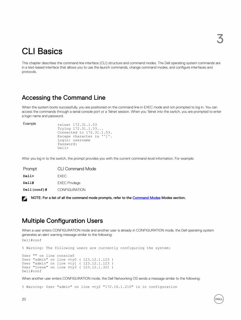
3CLI BasicsThis chapter describes the command line interface (CLI) structure and command modes. The Dell operating system commands are in a text-based interface that allows you to use the launch commands, change command modes, and configure interfaces and protocols.
Accessing the Command LineWhen the system boots successfully, you are positioned on the command line in EXEC mode and not prompted to log in. You can access the commands through a serial console port or a Telnet session. When you Telnet into the switch, you are prompted to enter a login name and password.
Example telnet 172.31.1.53Trying 172.31.1.53...Connected to 172.31.1.53.Escape character is '^]'.Login: usernamePassword: Dell>
After you log in to the switch, the prompt provides you with the current command-level information. For example:
Prompt CLI Command Mode
Dell> EXEC
Dell# EXEC Privilege
Dell(conf)# CONFIGURATION
NOTE: For a list of all the command mode prompts, refer to the Command Modes Modes section.
Multiple Configuration UsersWhen a user enters CONFIGURATION mode and another user is already in CONFIGURATION mode, the Dell operating system generates an alert warning message similar to the following:
Dell#conf
% Warning: The following users are currently configuring the system:
User "" on line console0User "admin" on line vty0 ( 123.12.1.123 )User "admin" on line vty1 ( 123.12.1.123 )User "Irene" on line vty3 ( 123.12.1.321 )Dell#confWhen another user enters CONFIGURATION mode, the Dell Networking OS sends a message similar to the following:
% Warning: User "admin" on line vty2 "172.16.1.210" is in configuration
20

In this case, the user is “admin” on vty2.
Navigating the CLIThe Dell Networking OS displays a CLI prompt comprised of the host name and CLI mode.
• Host name is the initial part of the prompt and is “Dell” by default. You can change the host name with the hostname command.
• CLI mode is the second part of the prompt and reflects the current CLI mode. For a list of the Dell Networking OS command modes, refer to the command mode list in the Accessing the Command Line section.
The CLI prompt changes as you move up and down the levels of the command structure. Starting with CONFIGURATION mode, the command prompt adds modifiers to further identify the mode. For more information about command modes, refer to the Command Modes section.
Prompt CLI Command Mode
Dell> EXEC
Dell# EXEC Privilege
Dell(conf)# CONFIGURATION
Dell(conf-if-te-0/0)#
Dell(conf-if-vl-1)#
Dell(conf-if-ma-0/0)#
Dell(conf-if-range)#
INTERFACE
Dell(conf-line-console)#
Dell(conf-line-vty)#
LINE
Dell(conf-mon-sess)# MONITOR SESSION
Obtaining HelpAs soon as you are in a command mode there are several ways to access help.
To obtain a list of keywords at any command mode:
Type a ? at the prompt or after a keyword. There must always be a space before the ?.
To obtain a list of keywords with a brief functional description:
Type help at the prompt.
To obtain a list of available options:
Type a keyword and then type a space and a ?.
To obtain a list of partial keywords using a partial keyword:
Type a partial keyword and then type a ?.
21

Example The following is an example of typing ip ? at the prompt:
Dell(conf)#ip ?igmp Internet Group Management Protocolroute Establish static routestelnet Specify telnet options
When entering commands, you can take advantage of the following timesaving features:
• The commands are not case-sensitive.
• You can enter partial (truncated) command keywords. For example, you can enter int tengig int for the interface tengigabitethernet interface command.
• To complete keywords in commands, use the TAB key.
• To display the last enabled command, use the up Arrow key.
• To erase the previous character, use either the Backspace key or Delete key.
• To navigate left or right in the Dell Networking OS command line, use the left and right Arrow keys.
The shortcut key combinations at the Dell Networking OS command line are as follows:
Key Combination Action
CNTL-A Moves the cursor to the beginning of the command line.
CNTL-B Moves the cursor back one character.
CNTL-D Deletes the character at the cursor.
CNTL-E Moves the cursor to the end of the line.
CNTL-F Moves the cursor forward one character.
CNTL-I Completes a keyword.
CNTL-K Deletes all the characters from the cursor to the end of the command line.
CNTL-L Re-enters the previous command.
CNTL-N Returns to the more recent commands in the history buffer after recalling commands with Ctrl-P or the up Arrow key.
CNTL-P Recalls commands, beginning with the last command.
CNTL-U Deletes the line.
CNTL-W Deletes the previous word.
CNTL-X Deletes the line.
CNTL-Z Comes back to EXEC mode from any CONFIGURATION mode.
Esc B Moves the cursor back one word.
Esc F Moves the cursor forward one word.
Esc D Deletes all the characters from the cursor to the end of the word.
22

Using the Keyword no CommandTo disable, delete or return to default values, use the no form of the commands.
For most commands, if you type the keyword no in front of the command, you disable that command or delete it from the running
configuration. In this guide, the no form of the command is described in the Syntax portion of the command description. For
example:
Syntax no {boot | default | enable | ftp-server | hardware | hostname | ip | line | logging | monitor | service | io-aggregator broadcast storm-control | snmp-server | username}
Defaults None
Command Modes CONFIGURATION
Supported Modes All Modes
Command HistoryVersion Description
9.4(0.0) Supported on the FN I/O Aggregator.
8.3.17.0 Supported on the M I/O Aggregator.
Filtering show CommandsTo find specific information, display certain information only or begin the command output at the first instance of a regular expression or phrase, you can filter the display output of a show command.
When you execute a show command, and then enter a pipe ( | ), one of the following parameters, and a regular expression, the
resulting output either excludes or includes those parameters.
NOTE: The Dell Networking OS accepts a space before or after the pipe, no space before or after the pipe, or any combination. For example: Dell#command | grep TenGig|except regular-expression | find regular-expression.
except displays only the text that does not match the pattern (or regular expression)
find searches for the first occurrence of a pattern
grep displays text that matches a pattern.
no-more does not paginate the display output
save copies the output to a file for future use
The grep command option has an ignore-case sub-option that makes the search case-insensitive. For example, the commands:
• show run | grep Ethernet returns a search result with instances containing a capitalized “Ethernet,” such as interface TenGigabitEthernet 0/1.
• show run | grep ethernet does not return the search result above because it only searches for instances containing a non-capitalized “ethernet”.
• show run | grep Ethernet ignore-case returns instances containing both “Ethernet” and “ethernet”.
23

Displaying All Output
To display the output all at once (not one screen at a time), use the no-more option after the pipe. This operation is similar to the
terminal length screen-length command except that the no-more option affects the output of just the specified
command. For example:
Dell#show running-config|no-more
Filtering the Command Output Multiple Times
You can filter a single command output multiple times. To filter a command output multiple times, place the save option as the last
filter. For example:
Dell# command | grep regular-expression | except regular-expression | grep other-regular-expression | find regular-expression | no-more | save
Command ModesTo navigate and launch various CLI modes, use specific commands. Navigation to these modes is described in the following sections.
EXEC Mode
When you initially log in to the switch, by default, you are logged in to EXEC mode. This mode allows you to view settings and enter EXEC Privilege mode, which is used to configure the device.
When you are in EXEC mode, the > prompt is displayed following the host name prompt, which is “Dell” by default. You can change the host name prompt using the hostname command.
NOTE: Each mode prompt is preceded by the host name.
EXEC Privilege Mode
The enable command accesses EXEC Privilege mode. If an administrator has configured an “Enable” password, you are prompted
to enter it.
EXEC Privilege mode allows you to access all the commands accessible in EXEC mode, plus other commands, such as to clear address resolution protocol (ARP) entries and IP addresses. In addition, you can access CONFIGURATION mode to configure interfaces, routes and protocols on the switch. While you are logged in to EXEC Privilege mode, the # prompt displays.
CONFIGURATION Mode
In EXEC Privilege mode, use the configure command to enter CONFIGURATION mode and configure routing protocols and
access interfaces.
To enter CONFIGURATION mode:
1. Verify that you are logged in to EXEC Privilege mode.
2. Enter the configure command. The prompt changes to include (conf).
From this mode, you can enter INTERFACE mode by using the interface command.
INTERFACE Mode
To configure interfaces or IP services on those interfaces, use INTERFACE mode. An interface can be physical (for example, a TenGigabit Ethernet port) or virtual (for example, the VLAN interface).
24

To enter INTERFACE mode:
1. Verify that you are logged in to CONFIGURATION mode.
2. Enter the interface command and then enter an interface type and interface number that is available on the switch.
The prompt changes to include the designated interface and slot/port number. For example:
Prompt Interface Type
Dell(conf-if-te-0/1)#
Ten-Gigabit Ethernet interface then slot/port information
Dell(conf-if-vl-1)#
VLAN Interface then VLAN number (range 1–4094)
Dell(conf-if-ma-0/1)#
Management Ethernet interface then slot/port information
Dell(conf-if-range)#
Designated interface range (used for bulk configuration)
LINE Mode
To configure the console or virtual terminal parameters, use LINE mode.
To enter LINE mode:
1. Verify that you are logged in to CONFIGURATION mode.
2. Enter the line command. Include the keywords console or vty and their line number available on the switch. The prompt changes to include (config-line-console) or (config-line-vty).
You can exit this mode by using the exit command.
MONITOR SESSION Mode
In CONFIGURATION mode, use the monitor session command to enter MONITOR SESSION mode and configure port
monitoring.
To enter MONITOR SESSION mode:
1. Verify that you are logged in to CONFIGURATION mode.
2. Use the monitor session command. Include the monitor session ID. The prompt changes to include (conf-mon-sess).
You can return to CONFIGURATION mode by using the exit command.
PROTOCOL LLDP Mode
In CONFIGURATION mode, use the protocol lldp command to enter PROTOCOL LLDP mode and configure the LLDP
protocol.
To enter PROTOCOL LLDP mode:
1. Verify that you are logged in to CONFIGURATION mode.
2. Enter the protocol lldp command. The prompt changes to include Dell(config-lldp).
You can return to CONFIGURATION mode by using the exit command.
25

Track Login ActivityDell Networking OS enables you to track the login activity of users and view the successful and unsuccessful login events.
When you log in using the console or VTY line, the system displays the last successful login details of the current user and the number of unsuccessful login attempts since your last successful login to the system. The system stores the number of unsuccessful login attempts that have occurred in the last 30 days by default. You can change the default value to any number of days from 1 to 30. By default, login activity tracking is disabled. You can enable it using the login statistics enable command from the
configuration mode.
Restrictions for Tracking Login Activity
These restrictions apply for tracking login activity:
• Only the system and security administrators can configure login activity tracking and view the login activity details of other users.
• Login statistics is not applicable for login sessions that do not use user names for authentication. For example, the system does not report login activity for a telnet session that prompts only a password.
Configuring Login Activity Tracking
To enable and configure login activity tracking, follow these steps:
1. Enable login activity tracking.
CONFIGURATION mode
login statistics enable
After enabling login statistics, the system stores the login activity details for the last 30 days.
2. (Optional) Configure the number of days for which the system stores the user login statistics. The range is from 1 to 30.
CONFIGURATION mode
login statistics time-period days
Example of Configuring Login Activity Tracking
The following example enables login activity tracking. The system stores the login activity details for the last 30 days.
Dell(config)#login statistics enableThe following example enables login activity tracking and configures the system to store the login activity details for 12 days.
Dell(config)#login statistics enableDell(config)#login statistics time-period 12
Display Login Statistics
To view the login statistics, use the show login statistics command.Example of the show login statistics Command
The show login statistics command displays the successful and failed login details of the current user in the last 30 days or
the custom defined time period.
Dell#show login statistics
------------------------------------------------------------------User: adminLast login time: Mon Feb 16 04:40:00 2015Last login location: Line vty0 ( 10.14.1.97 )Unsuccessful login attempt(s) since the last successful login: 0Unsuccessful login attempt(s) in last 30 day(s): 3------------------------------------------------------------------
26

Example of the show login statistics all command
The show login statistics all command displays the successful and failed login details of all users in the last 30 days or
the custom defined time period.
Dell#show login statistics all
------------------------------------------------------------------User: adminLast login time: Mon Feb 16 04:40:00 2015Last login location: Line vty0 ( 10.14.1.97 )Unsuccessful login attempt(s) since the last successful login: 0Unsuccessful login attempt(s) in last 7 day(s): 3------------------------------------------------------------------
------------------------------------------------------------------User: secadmLast login time: Mon Feb 16 04:45:29 2015Last login location: Line vty0 ( 10.14.1.97 )Unsuccessful login attempt(s) since the last successful login: 0Unsuccessful login attempt(s) in last 7 day(s): 0------------------------------------------------------------------Example of the show login statistics user user-id command
The show login statistics user user-id command displays the successful and failed login details of a specific user in
the last 30 days or the custom defined time period.
Dell#show login statistics user admin
------------------------------------------------------------------User: adminLast login time: Mon Feb 16 04:40:00 2015Last login location: Line vty0 ( 10.14.1.97 )Unsuccessful login attempt(s) since the last successful login: 0Unsuccessful login attempt(s) in last 11 day(s): 3------------------------------------------------------------------
Limit Concurrent Login SessionsDell Networking OS enables you to limit the number of concurrent login sessions of users on VTY, Aux, and console lines. You can also clear any of your existing sessions when you reach the maximum permitted number of concurrent sessions.
By default, you can use all 10 VTY lines, one console line, and one Aux line. You can limit the number of available sessions using the login concurrent-session limit command and so restrict users to that specific number of sessions. You can optionally
configure the system to provide an option to the users to clear any of their existing sessions.
Restrictions for Limiting the Number of Concurrent Sessions
These restrictions apply for limiting the number of concurrent sessions:
• Only the system and security administrators can limit the number of concurrent sessions and enable the clear-line option.
• Users can clear their existing sessions only if the system is configured with the login concurrent-session clear-line enable command.
Configuring Concurrent Session Limit
To configure concurrent session limit, follow this procedure:
• Limit the number of concurrent sessions for all users.
CONFIGURATION mode
27

login concurrent-session limit number-of-sessions
Example of Configuring Concurrent Session Limit
The following example limits the permitted number of concurrent login sessions to 4.
Dell(config)#login concurrent-session limit 4
Enabling the System to Clear Existing Sessions
To enable the system to clear existing login sessions, follow this procedure:
• Use the following command.
CONFIGURATION mode
login concurrent-session clear-line enable
Example of Enabling the System to Clear Existing Sessions
The following example enables you to clear your existing login sessions.
Dell(config)#login concurrent-session clear-line enableExample of Clearing Existing Sessions
When you try to login, the following message appears with all your existing concurrent sessions, providing an option to close any one of the existing sessions:
$ telnet 10.11.178.14Trying 10.11.178.14...Connected to 10.11.178.14.Escape character is '^]'.Login: adminPassword:Current sessions for user admin:Line Location2 vty 0 10.14.1.973 vty 1 10.14.1.97Clear existing session? [line number/Enter to cancel]:When you try to create more than the permitted number of sessions, the following message appears, prompting you to close one of the existing sessions. If you close any of the existing sessions, you are allowed to login. :
$ telnet 10.11.178.17Trying 10.11.178.17...Connected to 10.11.178.17.Escape character is '^]'.Login: adminPassword:
Maximum concurrent sessions for the user reached.Current VTY sessions for user admin:Line Location2 vty 0 10.14.1.973 vty 1 10.14.1.974 vty 2 10.14.1.975 vty 3 10.14.1.97Kill existing session? [line number/Enter to cancel]:
28

4File ManagementThis chapter contains commands needed to manage the configuration files and includes other file management commands.
The commands in this chapter are supported by the Dell Networking OS.
boot system gatewaySpecify the IP address of the default next-hop gateway for the management subnet.
Syntax boot system gateway ip-addressParameters
ip-address Enter an IP address in dotted decimal format.
Command Modes CONFIGURATION
Supported Modes All Modes
Command HistoryVersion Description
9.4(0.0) Supported on the FN I/O Aggregator.
8.3.17.0 Supported on the M I/O Aggregator.
Usage Information Saving the address to the startup configuration file preserves the address in NVRAM in case the startup configuration file is deleted.
boot system stack-unitSpecify the location of the Dell Networking OS image to be used to boot the system.
Syntax boot system stack-unit <0-5 | all> {default | primary | secondary}Parameters
0-5 Enter the stack member unit identifier of the stack member.
all Enter the keyword all to set the primary, secondary, and default images for the
system.
default Enter the keyword default to set the default image path for the system.
primary Enter the keyword primary to set the primary image path for the system.
secondary Enter the keyword secondary to set the secondary image path for the system.
29

Command Modes CONFIGURATION
Supported Modes All Modes
Command HistoryVersion Description
8.3.17.0 Supported on the M I/O Aggregator.
9.4(0.0) Supported on the FN I/O aggregator.
Usage Information The system first attempts to load the image from the primary path. If it fails to boot, the system tries to load the image from the secondary path and if that also fails, the system loads the default image.
cdChange to a different working directory.
Syntax cd directoryParameters
directory (OPTONAL) Enter one of the following:
• flash: (internal Flash) or any sub-directory
• usbflash: (external Flash) or any sub-directory
Command Modes EXEC Privilege
Supported Modes All Modes
Command HistoryVersion Description
9.4(0.0) Supported on the FN I/O Aggregator.
8.3.17.0 Supported on the M I/O Aggregator.
copyCopy one file to another location. The Dell Networking OS supports IPv4 addressing for FTP, TFTP, and SCP (in the hostip field).
Syntax copy source-file-url destination-file-urlParameters
file-url Enter the following location keywords and information:
• To copy a file from the internal FLASH, enter flash:// then the filename.
• To copy the running configuration, enter the keywords running-config.
• To copy the startup configuration, enter the keywords startup-config.
• To copy a file on the external FLASH, enter usbflash:// then the filename.
Command Modes EXEC Privilege
30

Supported Modes All Modes
Command HistoryVersion Description
9.4(0.0) Supported on the FN I/O Aggregator.
8.3.17.0 Supported on the M I/O Aggregator.
Usage Information The Dell Networking OS supports a maximum of 100 files, at the root directory level, on both the internal and external Flash.
The usbflash commands are supported. For a list of approved USB vendors, refer to the Dell Networking
OS Release Notes.
When copying a file to a remote location (for example, using Secure Copy [SCP]), enter only the keywords and Dell Networking OS prompts you for the rest of the information.
NOTE: Dell Networking OS imposes a length limit on the password you create for performing the secure copy operation. Your password can be no longer than 32 characters.
For example, when using SCP, you can enter the copy running-config scp: command. The running-
config is the source and the target is specified in the ensuing prompts. Dell Networking OS prompts you to enter any required information, as needed for the named destination — remote destination, destination filename, user ID and password, and so forth.
When you use the copy running-config startup-config command to copy the running
configuration (the startup configuration file amended by any configuration changes made because the system was started) to the startup configuration file, Dell Networking OS creates a backup file on the internal flash of the startup configuration.
The Dell Networking OS supports copying the running-configuration to a TFTP server or to an FTP server:
• copy running-config tftp:• copy running-config ftp:
NOTE: Dell Networking OS imposes a length limit on the password you create for accessing the FTP server. Your password can be no longer than 32 characters.
In the copy scp: flash: example, specifying SCP in the first position indicates that the target to
specify in the ensuing prompts. Entering flash: in the second position means that the target is the
internal Flash. In this example, the source is on a secure server running SSH, so you are prompted for the UDP port of the SSH server on the remote host.
Example (running-config scp:)
Dell#copy running-config scp:Address or name of remote host []: 10.10.10.1Port number of the server [22]: 99Destination file name [startup-config]: old_runningUser name to login remote host: sburgessPassword to login remote host:
Password to login remote host? dilling
Example (copy scp:) Dell#copy scp: flash:Address or name of remote host []: 10.11.199.134Port number of the server [22]: 99Source file name []: test.cfgUser name to login remote host: admin
31

Password to login remote host:Destination file name [test.cfg]: test1.cfg
Related Commands cd — Changes the working directory.
copy running-config startup-configCopy running configuration to the startup configuration.
Syntax copy running-config startup-config {duplicate}Command Modes EXEC Privilege
Supported Modes All Modes
Command HistoryVersion Description
9.4(0.0) Supported on the FN I/O Aggregator.
8.3.17.0 Supported on the M I/O Aggregator.
Usage Information This command is useful for quickly making a change configuration on one chassis available on external flash to move it to another chassis.
deleteDelete a file from the flash. After deletion, files cannot be restored.
Syntax delete flash: ([flash://]filepath) usbflash ([usbflash://]filepath)Parameters
flash-url Enter the following location and keywords:
• For a file or directory on the internal Flash, enter flash:// then the filename or directory name.
• For a file or directory on an external USB drive, enter usbflash:// then the filename or directory name.
no-confirm (OPTIONAL) Enter the keywords no-confirm to specify that the Dell
Networking OS does not require user input for each file prior to deletion.
Command Modes EXEC Privilege
Supported Modes All Modes
Command HistoryVersion Description
9.4(0.0) Supported on the FN I/O Aggregator.
8.3.17.0 Supported on the M I/O Aggregator
32

dirDisplays the files in a file system. The default is the current directory.
Syntax dir [filename | directory name:]Parameters
filename | directory name:
(OPTIONAL) Enter one of the following:
• For a file or directory on the internal Flash, enter flash:// then the filename or directory name.
• For a file or directory on an external USB drive, enter usbflash:// then the filename or directory name.
Command Modes EXEC Privilege
Supported Modes All Modes
Command HistoryVersion Description
9.4(0.0) Supported on the FN I/O Aggregator.
8.3.17.0 Supported on the M I/O Aggregator.
Example Dell#dirDirectory of flash:
1 drwx 4096 Jan 01 1980 00:00:00 +00:00 .2 drwx 2048 Mar 06 2010 00:36:21 +00:00 ..3 drwx 4096 Feb 25 2010 23:32:50 +00:00 TRACE_LOG_DIR4 drwx 4096 Feb 25 2010 23:32:50 +00:00 CORE_DUMP_DIR5 d--- 4096 Feb 25 2010 23:32:50 +00:00 ADMIN_DIR6 -rwx 720969768 Mar 05 2010 03:25:40 +00:00 6gb7 -rwx 4260 Mar 03 2010 22:04:50 +00:00 prem-23-5-128 -rwx 31969685 Mar 05 2010 17:56:26 +00:00DellS-XL-8-3-16-148.bin9 -rwx 3951 Mar 06 2010 00:36:18 +00:00 startup-config
flash: 2143281152 bytes total (1389801472 bytes free)Dell#
Related Commands cd — Changes the working directory.
format flashErase all existing files and reformat the filesystem in the internal flash memory. After the filesystem is formatted, files cannot be restored.
Syntax format {flash: | usbflash:}Defaults flash memory
Command Modes EXEC Privilege
Supported Modes All Modes
Command HistoryVersion Description
9.4(0.0) Supported on the FN I/O Aggregator.
33

Version Description
8.3.17.0 Supported on the M I/O Aggregator.
Usage Information You must include the colon (:) when entering this command.
CAUTION: This command deletes all files, including the startup configuration file. So, after executing this command, consider saving the running config as the startup config (use the write memory command or copy run start command).
Related Commands copy – copies the current configuration to either the startup-configuration file or the terminal.
show file – displays the contents of a text file in the local filesystem.
show file-systems – displays information about the file systems on the system.
HTTP Copy via CLICopy one file to another location. Dell Networking OS supports IPv4 and IPv6 addressing for FTP, TFTP, and SCP (in the hostip field).
Syntax copy http://10.16.206.77/sample_file flash://sample_filecopy flash://sample_file http://10.16.206.77/sample_fileYou can copy from the server to the switch and vice-versa.
Parameters copy http: flash:
Address or name of remote host []: 10.16.206.77
Port number of the server [80]:
Source file name []: sample_file
User name to login remote host: x
Password to login remote host:
Destination file name [sample_file]:
Defaults None.
Command Modes EXEC
Supported Modes All Modes
Command HistoryVersion Description
9.4(0.0) Introduced on the FN I/O Aggregator.
9.3(0.1) Introduced on the M I/O Aggregator.
Example copy http://admin:[email protected]/sample_file flash://sample_file
Related Commands copy ftp:flash
34

Copy files from FTP server to switch
logging coredump stack-unitEnable the coredump.
Syntax logging coredump stack-unit allCommand Modes CONFIGURATION
Supported Modes All Modes
Command HistoryVersion Description
9.4(0.0) Supported on the FN I/O Aggregator.
8.3.17.0 Supported on the M I/O Aggregator.
Usage Information The Kernel core dump can be large and may take up to five to 30 minutes to upload. The Dell Networking OS does not overwrite application core dumps so delete them as necessary to conserve space on the flash; if the flash is out of memory, the coredump is aborted. The Dell Networking OS completes the coredump process and waits until the upload is complete before rebooting the system.
pwdDisplay the current working directory.
Syntax pwdCommand Modes EXEC Privilege
Supported Modes All Modes
Command HistoryVersion Description
9.4(0.0) Supported on the FN I/O Aggregator.
8.3.17.0 Supported on the M I/O Aggregator.
Example Dell#pwdflash:Dell#
Related Commands cd – changes the directory.
renameRename a file in the local file system.
Syntax rename url url
35

Parametersurl Enter the following keywords and a filename:
• For a file on the internal Flash, enter flash:// then the filename.
• For a file on an external USB drive, enter usbflash:// then the filename.
Command Modes EXEC Privilege
Supported Modes All Modes
Command HistoryVersion Description
9.4(0.0) Supported on the FN I/O Aggregator.
8.3.17.0 Supported on the M I/O Aggregator.
restore factory-defaultsRestore factory defaults.
Syntax restore factory-defaults stack-unit id {clear-all | nvram}Parameters
factory-defaults Return the system to its factory default mode.
id Enter the stack member unit identifier to restore the mentioned stack-unit. The range is from 0 to 6. Enter the keyword all to restore all units in the stack.
clear-all Enter the keywords clear-all to reset the NvRAM and the system startup
configuration.
nvram Enter the keyword nvram to reset the NvRAM only.
Command Modes EXEC Privilege
Supported Modes All Modes
Command HistoryVersion Description
9.4(0.0) Supported on the FN I/O aggregator.
8.3.17.0 Supported on the M I/O Aggregator.
Usage Information Restoring factory defaults deletes the existing startup configuration and all persistent settings (stacking, fanout, and so forth).
When restoring all units in a stack, all the units in the stack are placed into stand-alone mode.
When restoring a single unit in a stack, that unit placed in stand-alone mode. No other units in the stack are affected.
When restoring units in stand-alone mode, the units remin in stand-alone mode after the restoration. After the restore is complete, the units power cycle immediately.
CAUTION: There is no undo for this command.
36

Example Dell#restore factory-defaults stack-unit 0 clear-all*************************************************************** Warning - Restoring factory defaults will delete the existing ** startup-config and all persistent settings (stacking, fanout, etc.)** After restoration the unit(s) will be powercycled immediately. ** Proceed with caution ! ***************************************************************Proceed with factory settings? Confirm [yes/no]:yes-- Restore status --Unit Nvram Config------------------------0 Success SuccessPower-cycling the unit(s).Dell#
Example (NvRAM, all)
Dell#restore factory-defaults stack-unit all nvram*************************************************************** Warning - Restoring factory defaults will delete the existing ** persistent settings (stacking, fanout, etc.) ** All the units in the stack will be split into standalone units. ** After restoration the unit(s) will be powercycled immediately. ** Proceed with caution ! ***************************************************************Proceed with factory settings? Confirm [yes/no]:yes-- Restore status --Unit Nvram Config------------------------0 Success1 Success2 Success3 Not present4 Not present5 Not presentPower-cycling the unit(s).Dell#
Example (NvRAM, single unit)
Dell#restore factory-defaults stack-unit 1 nvram*************************************************************** Warning - Restoring factory defaults will delete the existing ** persistent settings (stacking, fanout, etc.) ** After restoration the unit(s) will be powercycled immediately. ** Proceed with caution ! ***************************************************************Proceed with factory settings? Confirm [yes/no]:yes-- Restore status --Unit Nvram Config------------------------1 SuccessPower-cycling the unit(s).Dell#
show boot systemDisplays information about boot images currently configured on the system.
Syntax show boot system stack-unit {0-5 | all}Parameters
0–5 Enter this information to display the boot image information of only the entered stack-unit.
37

all Enter the keyword all to display the boot image information of all the stack-units
in the stack.
Defaults none
Command Modes• EXEC
• EXEC Privilege
Supported Modes All Modes
Command HistoryVersion Description
9.4(0.0) Supported on the FN I/O Aggregator.
8.3.17.0 Supported on the M I/O Aggregator.
Example Dell#show boot system stack-unit allCurrent system image information in the system:=============================================Type Boot Type A B---------------------------------------------Stack-unit 0 is not present.Stack-unit 1 DOWNLOAD BOOT 9-1-0-218 9-1-0-202Stack-unit 2 is not present.Stack-unit 3 is not present.Stack-unit 4 is not present.Stack-unit 5 is not present.
show fileDisplays contents of a text file in the local filesystem.
Syntax show file urlParameters
url Enter one of the following:
• For a file on the internal Flash, enter flash:// then the filename.
• For a file on the external Flash, enter usbflash:// then the filename.
Command Modes EXEC Privilege
Supported Modes All Modes
Command HistoryVersion Description
9.4(0.0) Supported on the FN I/O Aggregator.
8.3.17.0 Supported on the M I/O Aggregator.
Example Dell#show file flash://startup-config! Version E8-3-17-38boot system stack-unit 1 primary tftp://10.11.9.21/dv-m1000e-2-b2boot system stack-unit 1 default system: A:boot system gateway 10.11.209.62!
38
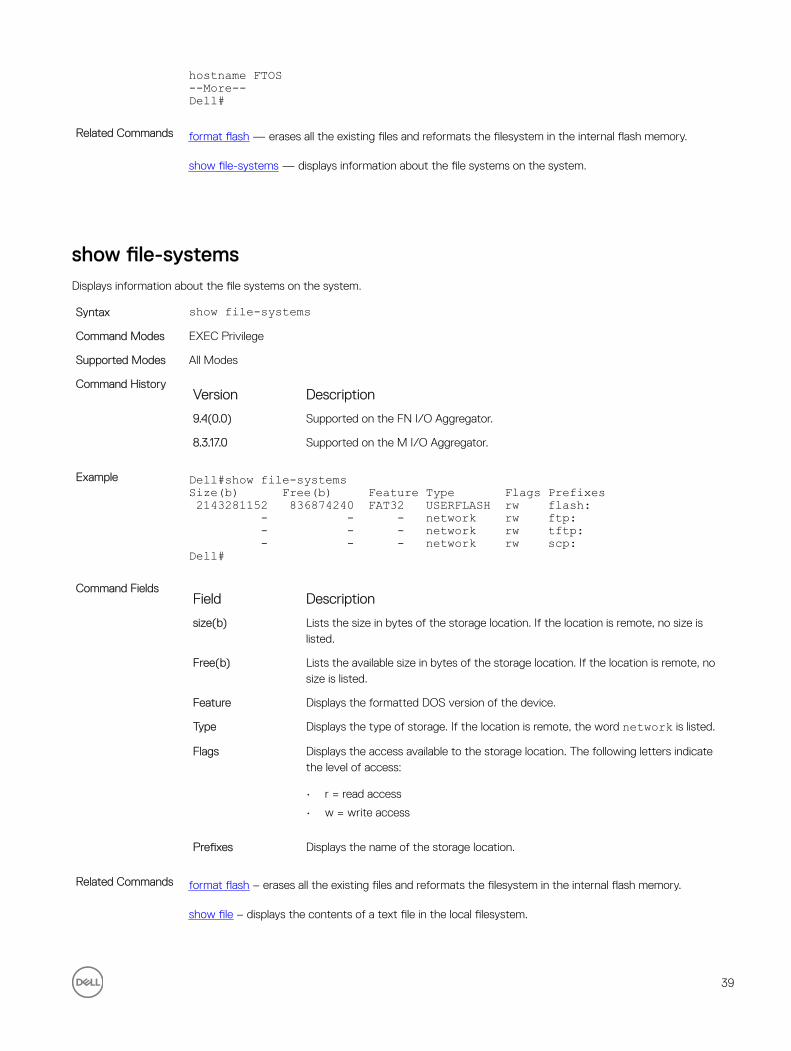
hostname FTOS--More--Dell#
Related Commands format flash — erases all the existing files and reformats the filesystem in the internal flash memory.
show file-systems — displays information about the file systems on the system.
show file-systemsDisplays information about the file systems on the system.
Syntax show file-systemsCommand Modes EXEC Privilege
Supported Modes All Modes
Command HistoryVersion Description
9.4(0.0) Supported on the FN I/O Aggregator.
8.3.17.0 Supported on the M I/O Aggregator.
Example Dell#show file-systemsSize(b) Free(b) Feature Type Flags Prefixes 2143281152 836874240 FAT32 USERFLASH rw flash: - - - network rw ftp: - - - network rw tftp: - - - network rw scp:Dell#
Command FieldsField Description
size(b) Lists the size in bytes of the storage location. If the location is remote, no size is listed.
Free(b) Lists the available size in bytes of the storage location. If the location is remote, no size is listed.
Feature Displays the formatted DOS version of the device.
Type Displays the type of storage. If the location is remote, the word network is listed.
Flags Displays the access available to the storage location. The following letters indicate the level of access:
• r = read access
• w = write access
Prefixes Displays the name of the storage location.
Related Commands format flash – erases all the existing files and reformats the filesystem in the internal flash memory.
show file – displays the contents of a text file in the local filesystem.
39

show os-versionDisplays the release and software image version information of the image file specified.
Syntax show os-version [file-url]Parameters
file-url (OPTIONAL) Enter the following location keywords and information:
• For a file on the internal Flash, enter flash:// then the filename.
• For a file on an FTP server, enter ftp://user:password@hostip/filepath.
• For a file on a TFTP server, enter tftp://hostip/filepath.
• For a file on the external Flash, enter usbflash://filepath then the filename.
Defaults none
Command Modes EXEC Privilege
Supported Modes All Modes
Command HistoryVersion Description
9.4(0.0) Supported on the FN I/O Aggregator.
8.3.17.0 Supported on the M I/O Aggregator.
Usage InformationNOTE: A filepath that contains a dot ( . ) is not supported.
Example Dell#show os-version
RELEASE IMAGE INFORMATION :--------------------------------------------------------------Platform Version Size ReleaseTimeIOM-Series: XL 8-3-17-38 31603078 Jul 19 2012 06:02:28
TARGET IMAGE INFORMATION :--------------------------------------------------------------Type Version Target checksumruntime 8-3-17-38 Control Processor passed
CPLD IMAGE INFORMATION :--------------------------------------------------------------Card CPLD Name VersionStack-unit 1 IOM SYSTEM CPLD 6Dell#
show running-configDisplays the current configuration and display changes from the default values.
Syntax show running-config [entity] [configured] [status]Parameters
entity (OPTIONAL) To display that entity’s current (non-default) configuration, enter one of the following keywords:
40

NOTE: If you did not configure anything for that entity, nothing displays and the prompt returns.
boot for the current boot configuration
ftp for the current FTP configuration
igmp for the current IGMP configuration
interface for the current interface configuration
line for the current line configuration
lldp for the current lldp configuration
logging for the current logging configuration
management-route
for the current Management port forwarding configuration
monitor for the current Monitor configuration
snmp for the current SNMP configuration
uplink-state-group
for the uplink state group configuration
users for the current users configuration
configured (OPTIONAL) Enter the keyword configured to display line card interfaces with
non-default configurations only.
status (OPTIONAL) Enter the keyword status to display the checksum for the running
configuration and the start-up configuration.
Command Modes EXEC Privilege
Supported Modes All Modes
Command HistoryVersion Description
9.4(0.0) Supported on the FN I/O aggregator.
8.3.17.0 Supported on the M I/O Aggregator.
Example Dell#show running-configCurrent Configuration ...! Version 9-4(0-180)!boot system stack-unit 0 primary tftp://10.11.8.12/dv-ci-stomp-tc-1-a1!redundancy auto-synchronize full!hostname Dell...
Example Dell#show running-config status
running-config bytes 5063, checksum 0xF6F801ACstartup-config bytes 4835, checksum 0x764D3787Dell#
41

Usage Information The status option allows you to display the size and checksum of the running configuration and the
startup configuration.
show versionDisplays the current Dell Networking OS version information on the system.
Syntax show versionCommand Modes EXEC Privilege
Supported Modes All Modes
Command HistoryVersion Description
9.4(0.0) Supported on the FN I/O Aggregator.
8.3.17.0 Supported on the M I/O Aggregator.
Example Dell#show versionDell Force10 Real Time Operating System SoftwareDell Force10 Operating System Version: 1.0Dell Force10 Application Software Version: E8-3-17-38Copyright (c) 1999-2012 by Dell Inc. All Rights Reserved.Build Time: Thu Jul 19 05:59:59 PDT 2012Build Path: /sites/sjc/work/swsystems01-2/ravisubramani/ravis-8317/SW/SRC/Cp_src/TacacsFTOS uptime is 4 day(s), 4 hour(s), 3 minute(s)System image file is "dv-m1000e-2-b2" System Type: I/O-AggregatorControl Processor: MIPS RMI XLP with 2147483648 bytes of memory.
256M bytes of boot flash memory.
1 34-port GE/TE (XL)56 Ten GigabitEthernet/IEEE 802.3 interface(s)
Command FieldsLines Beginning With
Description
Dell Force10 Network...
Name of the operating system
Dell Force10 Operating...
OS version number
Dell Force10 Application...
Software version
Copyright (c)... Copyright information
Build Time... Software build’s date stamp
Build Path... Location of the software build files loaded on the system
Dell Force10 uptime is...
Amount of time the system has been up
System image... Image file name
Chassis Type: System type (M I/O Aggregator)
42

Lines Beginning With
Description
Control Processor:...
Control processor information and amount of memory on processor
256M bytes... Amount of boot flash memory on the system
1 34 Port Hardware configuration of the system, including the number and type of physical interfaces available
upgrade bootUpgrade the bootflash image or bootselector image.
Syntax upgrade boot {all | bootflash-image | bootselector-image} stack-unit {0-5 | all} {booted | flash: |ftp: | tftp: | usbflash:} (A: | B:}
Parametersall Enter the keyword all to change both the bootflash and bootselecter images.
bootflash-image Enter the keywords bootflash-image to change the bootflash image.
bootselector-image Enter the keywords bootselector-image to change the bootselector image.
0–5 Enter the keyword 0–5 to upgrade only the mentioned stack-unit.
all Enter the keyword all to upgrade all the member stack-units.
booted Enter the keyword booted to upgradefrom the current image in the M I/O
Aggregator.
ftp: After entering the keyword ftp:, you can either follow it with the location of the
source file in this form: //userid:password@hostip/filepath or press
Enter to launch a prompt sequence.
tftp: After entering the keyword tftp:, you can either follow it with the location of the
source file in this form: //hostlocation/filepath or press Enter to launch a
prompt sequence.
flash: After entering the keyword flash:, you can either follow it with the location of
the source file in this form: //filepath or press Enter to launch a prompt
sequence.
usbflash: After entering the keyword usbflash:, you can either follow it with the location
of the source file in this form: //filepath or press Enter to launch a prompt
sequence.
A: Enter this keyword to upgrade the bootflash partition A.
B: Enter this keyword to upgrade the bootflash partition B.
Defaults none
Command Modes EXEC Privilege
Supported Modes All Modes
43

Command HistoryVersion Description
9.4(0.0) Supported on the FN I/O Aggregator.
8.3.17.0 Supported on the M I/O Aggregator.
Usage Information You must reload the Dell Networking OS after executing this command.
Example Dell#upgrade boot ?all Upgrade both boot flash image and selector imagebootflash-image Upgrade boot flash imagebootselector-image Upgrade boot selector imageDell#
upgrade systemUpgrade the bootflash image or system image.
Syntax upgrade system {flash: | ftp: | scp: | tftp: | usbflash: | stack-unit {0-5 | all} {A: | B:}
Parameters0–5 Enter the keyword 0–5 to upgrade only the mentioned stack-unit.
all Enter the keyword all to upgrade all the member units of the stack.
ftp After entering the keyword ftp you can either follow it with the location of the
source file in this form://userid:password@hostip/filepath, or press
Enter to launch a prompt sequence.
scp After entering the keyword scp you can either follow it with the location of the
source file in this form://userid:password@hostip/filepath, or press
Enter to launch a prompt sequence.
tftp After entering the keyword tftp you can either follow it with the location of the
source file in this form://hostlocation/filepath, or press Enter to launch a
prompt sequence.
flash After entering the keyword flash you can either follow it with the location of the
source file in this form://filepath, or press Enter to launch a prompt sequence.
usbflash After entering the keyword usbflash you can either follow it with the location of
the source file in this form://filepath, or press Enter to launch a prompt
sequence.
A: Enter this keyword to upgrade the bootflash partition A.
B: Enter this keyword to upgrade the bootflash partition B.
Defaults none
Command Modes EXEC Privilege
Supported Modes All Modes
44

Command HistoryVersion Description
9.4(0.0) Supported on the FN I/O Aggregator.
8.3.17.0 Supported on the M I/O Aggregator.
Usage Information You must reload Dell Networking OS after executing this command. Use the command upgrade system stack-unit to copy Dell Networking OS from the management unit to one or more stack members.
Example Dell#upgrade system ?flash: Copy from flash file system (flash://filepath)ftp: Copy from remote file system, IPv4 or IPv6, (ftp://userid:password@hostip/filepath)scp: Copy from remote file system, IPv4 or IPv6, (scp://userid:password@hostip/filepath)stack-unit Sync image to the stack-unittftp: Copy from remote file system, IPv4 or IPv6, (tftp://hostip/filepath)usbflash: Copy from usbflash file system (usbflash://filepath)Dell#
45

5Control and MonitoringThis chapter describes control and monitoring for the I/O Aggregator.
asset-tagAssign and store a unique asset-tag to the stack member.
Syntax asset-tag stack-unit unit id Asset-tag IDTo remove the asset tag, use the no stack-unit unit-id Asset-tag ID command.
Parametersstack-unit unit-id Enter the keywords stack-unit then the unit-id to assign a tag to the
specific member. The range is from 0 to 5.
Asset-tag ID Enter a unique asset-tag ID to assign to the stack member. This option accepts a maximum of 10 characters, including all special characters except double quotes. To include a space in the asset-tag, enter a space within double quotes.
Defaults No asset-tag is assigned.
Command Modes EXEC Privilege
Supported Modes All Modes
Command HistoryVersion Description
9.4(0.0) Supported on the FN I/O Aggregator.
9.2(0.0) Introduced on the M I/O Aggregator.
Related Commands show system— Displays the current status of all stack members or a specific member.
clear alarmsClear the alarms on the system.
Syntax clear alarmsCommand Modes EXEC Privilege
Supported Modes All Modes
Command HistoryVersion Description
9.4(0.0) Supported on the FN I/O Aggregator.
46

Version Description
8.3.17.0 Supported on the M I/O Aggregator.
Usage Information This command clears alarms that are no longer active. If an alarm situation is still active, it is seen in the system output.
clear command historyClear the command history log.
Syntax clear command historyCommand Modes EXEC Privilege
Supported Modes All Modes
Command HistoryVersion Description
9.4(0.0) Supported on the FN I/O Aggregator.
8.3.17.0 Supported on the M I/O Aggregator.
Related Commands show command-history— displays a buffered log of all the commands all users enter along with a time stamp.
configureEnter CONFIGURATION mode from EXEC Privilege mode.
Syntax configure [terminal]Parameters
terminal (OPTIONAL) Enter the keyword terminal to specify that you are configuring
from the terminal.
Command Modes EXEC Privilege
Supported Modes All Modes
Command HistoryVersion Description
9.4(0.0) Supported on the FN I/O Aggregator.
8.3.17.0 Supported on the M I/O Aggregator.
Example Dell#configureDell(conf)#
47

debug cpu-traffic-statsEnable the collection of computer processor unit (CPU) traffic statistics.
Syntax debug cpu-traffic-statsDefaults Disabled
Command Modes EXEC Privilege
Supported Modes All Modes
Command HistoryVersion Description
9.4(0.0) Supported on the FN I/O Aggregator.
8.3.17.0 Supported on the M I/O Aggregator.
Usage Information This command enables (and disables) the collection of CPU traffic statistics from the time this command is executed (not from system boot). However, excessive traffic a CPU receives automatically triggers (turn on) the collection of CPU traffic statics.
To view the traffic statistics, use the show cpu-traffic-stats command.
If the CPU receives excessive traffic, traffic is rate controlled.
NOTE: You must enable this command before the show cpu-traffic-stats command
displays traffic statistics. Dell Networking recommends disabling debugging (no debug cpu-traffic-stats) after troubleshooting is complete.
Related Commands show cpu-traffic-stats— displays the cpu traffic statistics.
debug ifm trace-flagsTurn on the IFM internal trace-flags.
Syntax debug ifm trace-flags trace-flagsTo disable this command, use the no debug ifm trace-flags command.
Parameterstrace-flags Enter a hexadecimal number representing the trace-flag.
Defaults None
Command Modes EXEC Privilege
Supported Modes All Modes
Command HistoryVersion Description
9.4(0.0) Supported on the FN I/O Aggregator.
8.3.17.0 Supported on the M I/O Aggregator.
NOTE: Use this command only when you are working directly with a technical support representative to troubleshoot a problem. Do not use this command unless a technical support representative instructs you to do so.
48

disableReturn to EXEC mode.
Syntax disable [level]Parameters
level (OPTIONAL) Enter a number for a privilege level of the Dell Networking OS. The range is from 0 to 15. The default is 1.
Defaults 1
Command Modes EXEC Privilege
Supported Modes All Modes
Command HistoryVersion Description
9.4(0.0) Supported on the FN I/O Aggregator.
8.3.17.0 Supported on the M I/O Aggregator.
enableEnter EXEC Privilege mode or any other privilege level configured. After entering this command, you may need to enter a password.
Syntax enable [level]Parameters
level (OPTIONAL) Enter a number for a privilege level of the Dell Networking OS. The range is from 0 to 15. The default is 15.
Defaults 15
Command Modes EXEC
Supported Modes All Modes
Command HistoryVersion Description
9.4(0.0) Supported on the FN I/O Aggregator.
8.3.17.0 Supported on the M I/O Aggregator.
Usage Information Users entering EXEC Privilege mode or any other configured privilege level can access configuration commands. To protect against unauthorized access, use the enable password command to configure a
password for the enable command at a specific privilege level. If no privilege level is specified, the default
is privilege level 15.
Related Commands enable password— configures a password for the enable command and to access a privilege level.
49

endReturn to EXEC Privilege mode from other command modes (for example, CONFIGURATION mode).
Syntax endCommand Modes
• CONFIGURATION
• LINE
• INTERFACE
• MONITOR SESSION
• PROTOCOL LLDP
Supported Modes All Modes
Command HistoryVersion Description
9.4(0.0) Supported on the FN I/O Aggregator.
8.3.17.0 Supported on the M I/O Aggregator.
Related Commands exit— returns to the lower command mode.
exitReturn to the lower command mode.
Syntax exitCommand Modes
• EXEC Privilege
• CONFIGURATION
• LINE
• INTERFACE
• PROTOCOL LLDP
Supported Modes All Modes
Command HistoryVersion Description
9.4(0.0) Supported on the FN I/O Aggregator.
8.3.17.0 Supported on the M I/O Aggregator.
Related Commands end — returns to EXEC Privilege mode.
ftp-server enableEnable FTP server functions on the system.
Syntax ftp-server enable
50

Defaults Disabled
Command Modes CONFIGURATION
Supported Modes All Modes
Command HistoryVersion Description
9.4(0.0) Supported on the FN I/O Aggregator.
8.3.17.0 Supported on the M I/O Aggregator.
Example morpheus% ftp 10.31.1.111Connected to 10.31.1.111.220 FTOS (1.0) FTP server readyName (10.31.1.111:dch): dch331 Password requiredPassword:230 User logged inftp> pwd257 Current directory is "flash:"ftp> dir200 Port set okay150 Opening ASCII mode data connectionsize date time name-------- ------ ------ -------- 512 Jul-20-2004 18:15:00 tgtimg 512 Jul-20-2004 18:15:00 diagnostic 512 Jul-20-2004 18:15:00 other 512 Jul-20-2004 18:15:00 tgt226 Transfer complete329 bytes received in 0.018 seconds (17.95 Kbytes/s)ftp>
Related Commands ftp-server topdir— sets the directory to be used for incoming FTP connections.
ftp-server username— sets a username and password for incoming FTP connections.
ftp-server topdirSpecify the top-level directory to be accessed when an incoming FTP connection request is made.
Syntax ftp-server topdir directoryParameters
directory Enter the directory path.
Defaults The internal flash is the default directory.
Command Modes CONFIGURATION
Supported Modes All Modes
Command HistoryVersion Description
9.4(0.0) Supported on the FN I/O Aggregator.
8.3.17.0 Supported on the M I/O Aggregator.
51

Usage Information After you enable FTP server functions with the ftp-server enable command, Dell Networking
recommends specifying a top-level directory path. Without a top-level directory path specified, the Dell Networking OS directs users to the flash directory when logging in to the FTP server.
Related Commands ftp-server enable — enables FTP server functions on the M I/O Aggregator.
ftp-server username— sets a username and password for incoming FTP connections to the M I/O Aggregator.
ftp-server usernameCreate a user name and associated password for incoming FTP server sessions.
Syntax ftp-server username username password [encryption-type] passwordParameters
username Enter a text string up to 40 characters long as the user name.
password password Enter the keyword password then a string up to 40 characters long as the
password. Without specifying an encryption type, the password is unencrypted.
encryption-type (OPTIONAL) After the keyword password, enter one of the following numbers:
• 0 (zero) for an unecrypted (clear text) password
• 7 (seven) for a hidden text password
Defaults Not enabled.
Command Modes CONFIGURATION
Supported Modes All Modes
Command HistoryVersion Description
9.4(0.0) Supported on the FN I/O Aggregator.
8.3.17.0 Supported on the M I/O Aggregator.
hostnameSet the host name of the system.
Syntax hostname nameParameters
name Enter a text string, up to 32 characters long.
Defaults Dell Networking Operating System (OS)
Command Modes CONFIGURATION
Supported Modes All Modes
52

Command HistoryVersion Description
9.4(0.0) Supported on the FN I/O Aggregator.
8.3.17.0 Supported on the M I/O Aggregator.
Usage Information The hostname is used in the prompt.
ip telnet server enableEnable the Telnet server on the switch.
Syntax ip telnet server enableTo disable the Telnet server, use the no ip telnet server enable command.
Defaults Enabled
Command Modes CONFIGURATION
Supported Modes All Modes
Command HistoryVersion Description
9.4(0.0) Supported on the FN I/O Aggregator.
8.3.17.0 Supported on the M I/O Aggregator.
ip telnet source-interfaceSet an interface’s IP address as the source address in outgoing packets for Telnet sessions.
Syntax ip telnet source-interface interfaceParameters
interface Enter the following keyword and slot/port or number information:
• For a 10-Gigabit Ethernet interface, enter the keyword TenGigabitEthernet followed by the slot/port information.
• For VLAN interface, enter the keyword vlan then a number from 1 to 4094.
Defaults The IP address on the system that is closest to the Telnet address is used in the outgoing packets.
Command Modes CONFIGURATION
Supported Modes All Modes
Command HistoryVersion Description
9.4(0.0) Supported on the FN I/O Aggregator.
8.3.17.0 Supported on the M I/O Aggregator.
53

Related Commands telnet — telnets to another device.
lineEnable and configure console and virtual terminal lines to the system. This command accesses LINE mode, where you can set the access conditions for the designated line.
Syntax line {console 0 | vty number [end-number]}Parameters
console 0 Enter the keyword console 0 to configure the console port.
The console option is <0-0>.
vty number Enter the keyword vty followed by a number from 0 to 9 to configure a virtual
terminal line for Telnet sessions.
The system supports 10 Telnet sessions.
end-number (OPTIONAL) Enter a number from 1 to 9 as the last virtual terminal line to configure.
You can configure multiple lines at one time.
Defaults Not configured
Command Modes CONFIGURATION
Supported Modes All Modes
Command HistoryVersion Description
9.4(0.0) Supported on the FN I/O Aggregator.
8.3.17.0 Supported on the M I/O Aggregator.
Usage Information You cannot delete a terminal connection.
Related Commands show memory— View current memory usage on the M I/O Aggregator.
pingTest connectivity between the system and another device by sending echo requests and waiting for replies.
Syntax ping hostParameters
host Enter the host name or the destination IP address of the device to which you are testing connectivity.
Command Modes• EXEC
• EXEC Privilege
54

Supported Modes All Modes
Command HistoryVersion Description
9.4(0.0) Supported on the FN I/O Aggregator.
Usage Information When you enter the ping command without specifying an IP address (Extended Ping), you are prompted
for a target IP address, a repeat count, a datagram size (up to 1500 bytes), a timeout (in seconds), and for Extended Commands. For information on the ICMP message codes that return from a ping command,
refer to Internet Control Message Protocol (ICMP) Message Types.
Example (IPv4) Dell#ping 172.31.1.255
Type Ctrl-C to abort.
Sending 5, 100-byte ICMP Echos to 172.31.1.255, timeout is 2 seconds:Reply to request 1 from 172.31.1.208 0 msReply to request 1 from 172.31.1.216 0 msReply to request 1 from 172.31.1.205 16 ms::Reply to request 5 from 172.31.1.209 0 msReply to request 5 from 172.31.1.66 0 msReply to request 5 from 172.31.1.87 0 msDell#
reloadReboot the Dell Networking OS.
Syntax reloadCommand Modes EXEC Privilege
Supported Modes All Modes
Command HistoryVersion Description
9.4(0.0) Supported on the FN I/O Aggregator.
8.3.17.0 Supported on the M I/O Aggregator.
Usage Information If there is a change in the configuration, the Dell Networking OS prompts you to save the new configuration. Or you can save your running configuration with the copy running-config command.
Related Commands reset stack-unit — resets any designated stack member except the management unit.
service timestampsAdd time stamps to debug and log messages. This command adds either the uptime or the current time and date.
Syntax service timestamps [debug | log] [datetime [localtime] [msec] [show-timezone] | uptime]
Parametersdebug (OPTIONAL) Enter the keyword debug to add timestamps to debug messages.
55

log (OPTIONAL) Enter the keyword log to add timestamps to log messages with
severity from 0 to 6.
datetime (OPTIONAL) Enter the keyword datetime to have the current time and date
added to the message.
localtime (OPTIONAL) Enter the keyword localtime to include the localtime in the
timestamp.
msec (OPTIONAL) Enter the keyword msec to include milliseconds in the timestamp.
show-timezone (OPTIONAL) Enter the keyword show-timezone to include the time zone
information in the timestamp.
uptime (OPTIONAL) Enter the keyword uptime to have the timestamp based on time
elapsed since system reboot.
Defaults Not configured.
Command Modes CONFIGURATION
Supported Modes All Modes
Command HistoryVersion Description
9.4(0.0) Supported on the FN I/O Aggregator.
8.3.17.0 Supported on the M I/O Aggregator.
Usage Information If you do not specify parameters and enter service timestamps, it appears as service timestamps debug uptime in the running-configuration.
To view the current options set for the service timestamps command, use the show running-config command.
show alarmsDisplay the active major and minor alarms on the system.
Syntax show alarms [threshold]Command Modes
• EXEC
• EXEC Privilege
Supported Modes All Modes
Command HistoryVersion Description
9.4(0.0) Supported on the FN I/O Aggregator.
Example Dell# show alarms
-- Minor Alarms --Alarm Type Duration---------------------------------------No minor alarms
56

-- Major Alarms --Alarm Type Duration----------------------------------------No major alarms
Dell#
Dell# show alarms threshold
-- Temperature Limits (deg C) ------------------------------------------------------------------------------- Ingress-Air Off Ingress-Air Major Off Major Shutdown Unit0 58 61 84 86 90 Dell#
show command-historyDisplay a buffered log of all commands all users enter along with a time stamp.
Syntax show command-historyDefaults None
Command Modes• EXEC
• EXEC Privilege
Supported Modes All Modes
Command HistoryVersion Description
9.4(0.0) Supported on the FN I/O Aggregator.
8.3.17.0 Supported on the M I/O Aggregator.
Usage Information One trace log message is generated for each command. No password information is saved to this file.
Example Dell#show command-history[4/20 10:27:23]: CMD-(CLI):[enable]by default from console[4/20 10:27:23]: CMD-(CLI):[configure terminal]by default from console - Repeated 1 time.[4/20 10:27:23]: CMD-(CLI):[snmp-server community public ro]by default fromconsole[4/20 10:27:23]: CMD-(CLI):[logging 172.16.1.162]by default from console[4/20 10:27:23]: CMD-(CLI):[logging 10.10.10.4]by default from console[4/20 10:27:24]: CMD-(CLI):[logging 10.1.2.4]by default from console[4/20 10:27:24]: CMD-(CLI):[logging 172.31.1.4]by default from console[4/20 10:27:24]: CMD-(CLI):[logging 133.33.33.4]by default from console[4/20 10:27:24]: CMD-(CLI):[management route 172.16.1.0 /24 10.11.209.4]by defaultfrom console[4/20 10:27:24]: CMD-(CLI):[service timestamps log datetime]by default fromconsole[4/20 10:27:24]: CMD-(CLI):[line console 0]by default from console[4/20 10:27:24]: CMD-(CLI):[exec-timeout 0]by default from console[4/20 10:27:24]: CMD-(CLI):[exit]by default from console[4/20 10:27:29]: CMD-(CLI):[show version]by default from console[4/20 10:27:56]: CMD-(CLI):[show interfaces tengigabitethernet 0/3]by default fromconsole
57

[4/20 10:55:8]: CMD-(CLI):[show lldp neighbors]by default from console[4/20 15:17:6]: CMD-(CLI):[show cam-acl]by default from console[4/20 16:34:59]: CMD-(CLI):[show running-config interface tengigabitethernet 0/55]by default from console[4/20 16:38:14]: CMD-(CLI):[show vlan]by default from console[5/4 9:11:52]: CMD-(TEL0):[show version]by admin from vty0 (10.11.68.14)[5/4 9:12:9]: CMD-(TEL0):[show hosts]by admin from vty0 (10.11.68.14)[5/4 9:14:38]: CMD-(TEL0):[show arp]by admin from vty0 (10.11.68.14)[5/4 9:19:29]: CMD-(TEL0):[enable]by admin from vty0 (10.11.68.14)[5/4 9:19:35]: CMD-(TEL0):[configure]by admin from vty0 (10.11.68.14) - Repeated 1 time.[5/4 9:19:50]: CMD-(TEL0):[interface tengigabitethernet 0/16]by admin from vty0(10.11.68.14)[5/4 9:20:11]: CMD-(TEL0):[exit]by admin from vty0 (10.11.68.14)Dell#
Related Commands clear command history — clears the command history log.
show configuration lockDisplay the configuration lock status.
Syntax show configuration lockDefaults None
Command Modes EXEC Privilege
Supported Modes All Modes
Command HistoryVersion Description
9.4(0.0) Supported on the FN I/O Aggregator.
8.3.17.0 Supported on the M I/O Aggregator.
Usage Information The type may be auto, manual, or rollback. When set to auto, Dell Networking OS automatically denies access to CONFIGURATION mode to all other users every time the user on the listed VTY line enters CONFIGURATION mode. When set to manual, the user on the listed VTY line must explicitly set the lock each time before entering CONFIGURATION mode. Rollback indicates that Dell Networking OS is in a rollback process. The line number shown in the output can be used to send the messages to that session or release a lock on a VTY line.
Example Dell#show configuration lockConfigure exclusively locked by the following line:Line : vty 0Line number : 2User : adminType : AUTOState : LOCKEDIp address : 10.11.9.97Dell#
58

show cpu-traffic-statsDisplay the CPU traffic statistics.
Syntax show cpu-traffic-stats [port number | all]Parameters
port number (OPTIONAL) Enter the port number to display traffic statistics on that port only. The range is from 1 to 1568.
all (OPTIONAL) Enter the keyword all to display traffic statistics on all the interfaces
receiving traffic, sorted based on the traffic.
Defaults all
Command Modes EXEC
Supported Modes All Modes
Command HistoryVersion Description
9.4(0.0) Supported on the FN I/O Aggregator.
8.3.17.0 Supported on the M I/O Aggregator.
Usage Information Traffic statistics are sorted on a per-interface basis; the interface receiving the most traffic is displayed first. All CPU and port information is displayed unless a specific port or CPU is specified. Traffic information is displayed for router ports only; not for management interfaces. The traffic statistics are collected only after the debug cpu-traffic-stats command is executed; not from the system bootup.
NOTE: After debugging is complete, use the no debug cpu-traffic-stats command to shut
off traffic statistics collection.
Example Dell#show cpu-traffic-statsProcessor : CP-------------- Received 100% traffic on TenGigabitEthernet 8/2 Total packets:100 LLC:0, SNAP:0, IP:100, ARP:0, other:0 Unicast:100, Multicast:0, Broadcast:0Dell#
Related Commands debug cpu-traffic-stats — enables CPU traffic statistics for debugging.
show debuggingView a list of all enabled debugging processes.
Syntax show debuggingCommand Modes EXEC Privilege
Supported Modes All Modes
Command HistoryVersion Description
9.4(0.0) Supported on the FN I/O Aggregator.
8.3.17.0 Supported on the M I/O Aggregator.
59

Example Dell#show debugGeneric IP: (Access List: test) IP packet debugging is on for (Access List: test) TenGigabitEthernet 0/16 ICMP packet debugging is on for TenGigabitEthernet 0/16OSPF:1 OSPF packet debugging is onDHCP: DHCP debugging is onDell#
show diagDisplay the diagnostics information.
Syntax show diag {information | stack-unit number [detail | summary]] | testcase}Parameters
information Enter the keyword information to view current diagnostics information in the
system.
stack-unit unit-id (OPTIONAL) Enter the keywords stack-unit then the unit-id to display
information on a specific stack member. The range is from 0 to 5.
detail (OPTIONAL) Enter the keyword detail to view detailed diagnostics information.
summary (OPTIONAL) Enter the keyword summary to view a summary of the diagnostics
information.
testcase Enter the keyword testcase to view current diagnostics testcases available in
the system.
Defaults Summary
Command Modes EXEC Privilege
Supported Modes All Modes
Command HistoryVersion Description
9.4(0.0) Supported on the FN I/O Aggregator.
8.3.17.0 Supported on the M I/O Aggregator.
show environmentDisplays the system component status (for example, temperature or voltage).
Syntax show environment [all | stack-unit unit-id]Parameters
all Enter the keyword all to view all components.
stack-unit unit-id Enter the keywords stack-unit then the unit-id to display information on a specific
stack member. The range is from 0 to 5.
60

thermal sensor Enter the keywords thermal-sensor to view all components.
Command Modes• EXEC
• EXEC Privilege
Supported Modes All Modes
Command HistoryVersion Description
9.4(0.0) Supported on the FN I/O Aggregator.
8.3.17.0 Supported on the M I/O Aggregator.
Example (all) Dell#show environment all
-- Unit Environment Status --Unit Status Temp Voltage TempStatus---------------------------------------------------------------------------* 1 online 66C ok 2* Management Unit-- Thermal Sensor Readings (deg C) --Unit Sensor0 Sensor1 Sensor2 Sensor3 Sensor4 Sensor5 Sensor6 Sensor7Sensor8 Sensor9------------------------------------------------------------------------------------------------1 51 51 63 61 61 61 67 61 64 66Dell#
Example (stack-unit) Dell#show environment stack-unit
-- Unit Environment Status --Unit Status Temp Voltage TempStatus---------------------------------------------------------------------------* 1 online 66C ok 2* Management UnitDell#
Example (thermal-sensor)
Dell#show environment thermal-sensor
-- Thermal Sensor Readings (deg C) --Unit Sensor0 Sensor1 Sensor2 Sensor3 Sensor4 Sensor5 Sensor6 Sensor7Sensor8 Sensor9------------------------------------------------------------------------------------------------1 51 51 64 61 61 61 67 61 64 66Dell#
show inventoryDisplay the switch type, components (including media), and Dell Networking OS version including hardware identification numbers and configured protocols.
Syntax show inventory [media slot]
61

Parametersmedia slot (OPTIONAL) Enter the keyword media then the stack ID of the stack member you want to display pluggable media inventory.
Defaults none
Command Modes EXEC
Supported Modes All Modes
Command HistoryVersion Description
9.4(0.0) Supported on the FN I/O Aggregator.
Usage Information If there are no fiber ports in the unit, just the header under show inventory media displays. If there are fiber ports but no optics inserted, the output displays
"Media not present or accessible".
Example Dell#show inventory System Type : PE-FN-410S-IOA System Mode : 1.0 Software Version : 1-0(0-1859)
Unit Type Serial Number Part Number Rev Piece Part ID Rev Svc Tag Exprs Svc Code---------------------------------------------------------------------------------------------------------------------* 0 PowerEdge-FN-410S-IOA TW000000000020 07NVPVX01 X01 TW-07NVPV-00000-000-0020 X01 N/A N/A
* - Management Unit
Software Protocol Configured -------------------------------------------------------------- DCBX FIP Snooping IGMP iSCSI LLDP SNMP Dell#
Example (media) Dell#show inventory media ?<0-5> Slot number | Pipe through a command
Dell#show inventory media Slot Port Type Media Serial Number F10Qualified------------------------------------------------------------------------------ 0 9 SFP+ 10GBASE-SR AHJ0BU3 Yes 0 10 SFP+ 10GBASE-CU5M APF125100446U1 Yes 0 11 SFP+ 10GBASE-SR CD23FM12H Yes 0 12 SFP+ 10GBASE-SR CD23FM0XT Yes
Dell#
Related Commands show config (from INTERFACE VLAN mode) — displays information on a specific physical interface or virtual interface.
show memoryDisplay current memory usage on the M I/O Aggregator.
Syntax show memory [stack-unit 0–5]
62

Parametersstack-unit 0–5 (OPTIONAL) Enter the keywords stack-unit then the stack unit ID of the stack
member to display memory information on the designated stack member.
Command Modes• EXEC
• EXEC Privilege
Supported Modes All Modes
Command HistoryVersion Description
9.4(0.0) Supported on the FN I/O Aggregator.
8.3.17.0 Supported on the M I/O Aggregator.
Usage Information The output for show memory command displays the memory usage of LP part (sysdlp) of the system. The
sysdlp is an aggregate task that handles all the tasks running on the CPU.
Example Dell#show memory Statistics On Unit 0 Processor =========================== Total(b) Used(b) Free(b) Lowest(b) Largest(b)268435456 4010354 264425102 264375410 264425102
show processes cpuDisplay CPU usage information based on processes running.
Syntax show processes cpu [management-unit 1-99 [details] | stack-unit 0–5 | summary ]
Parametersmanagement-unit 1-99 [details]
(OPTIONAL) Display processes running in the control processor. The 1-99 variable
sets the number of tasks to display in order of the highest CPU usage in the past five (5) seconds. Add the keyword details to display all running processes
(except sysdlp). Refer to Example (management-unit).
stack-unit 0–5 (OPTIONAL) Enter the keywords stack-unit then the stack member ID. The
range is from 0 to 5.
As an option of the show processes cpu command, this option displays CPU
usage for the designated stack member. Or, as an option of memory, this option
limits the output of memory statistics to the designated stack member. Refer to Example (stack-unit).
summary (OPTIONAL) Enter the keyword summary to view a summary view CPU utilization
of processes related to line card processing. Refer to Example (summary).
Command Modes• EXEC
• EXEC Privilege
Supported Modes All Modes
63

Command HistoryVersion Description
9.4(0.0) Supported on the FN I/O Aggregator.
Example (summary) Dell#show processes cpu summary
CPU utilization 5Sec 1Min 5Min-------------------------------------------UNIT1 4% 3% 2%
Example (management-unit)
Dell#show processes cpu management-unit 5CPU utilization for five seconds: 4%/0%; one minute: 4%; five minutes: 4%PID Runtime(ms) Invoked uSecs 5Sec 1Min 5Min TTYProcess0x00000000 2120 212 10000 3.77% 3.77% 3.77% 0system0x00000112 2472940 247294 10000 0.79% 0.61% 0.65% 0sysdlp0x000000e4 495560 49556 10000 0.20% 0.25% 0.24% 0sysd0x0000013d 34310 3431 10000 0.00% 0.02% 0.00% 0lacp0x00000121 4190 419 10000 0.00% 0.02% 0.00% 0iscsiOpt
PID Runtime(ms) Invoked uSecs 5Sec 1Min 5Min TTY ProcessDell#
Example (stack-unit) Dell#show process cpu stack-unit 1CPU utilization for five seconds: 4%/0%; one minute: 3%; five minutes: 2%PID Runtime(ms) Invoked uSecs 5Sec 1Min 5Min TTY Process0x763a3000 17981680 1798168 10000 3.00% 2.67% 2.67% 0 KP0x762ba000 0 0 0 0.00% 0.00% 0.00% 0 debugagt0x762d9000 0 0 0 0.00% 0.00% 0.00% 0 F10StkMgr0x762f8000 214590 21459 10000 0.00% 0.00% 0.00% 0 lcMgr0x76319000 7890 789 10000 0.00% 0.00% 0.00% 0 dla0x76344000 155770 15577 10000 0.00% 0.00% 0.02% 0 sysAdmTsk0x76363000 583230 58323 10000 0.00% 0.00% 0.02% 0 timerMgr0x76381000 658850 65885 10000 0.00% 0.17% 0.08% 0 PM0x76299000 80110 8011 10000 0.00% 0.00% 0.00% 0 diagagt0x763c3000 0 0 0 0.00% 0.00% 0.00% 0 evagt--More--
Related Commands show diag — displays the data plane or management plane input and output statistics of the designated component of the designated stack member.
show hardware system-flow — displays Layer 3 ACL or QoS data for the selected stack member and stack member port-pipe.
show interfaces stack-unit — displays information on all interfaces on a specific stack member.
show processes memory — displays CPU usage information based on running processes.
64

show processes ipc flow-controlDisplay the single window protocol queue (SWPQ) statistics.
Syntax show processes ipc flow-control [cp] Parameters
cp (OPTIONAL) Enter the keyword cp to view the control processor’s SWPQ
statistics.
Defaults none
Command Modes• EXEC
• EXEC Privilege
Supported Modes All Modes
Command HistoryVersion Description
9.4(0.0) Supported on the FN I/O Aggregator.
8.3.17.0 Supported on the M I/O Aggregator.
Usage InformationField Description
Source QID /Tx Process
Source Service Identifier
Destination QID/Rx Process
Destination Service Identifier
Cur Len Current number of messages enqueued
High Mark Highest number of packets in the queue at any time
#of to / Timeout Timeout count
#of Retr /Retries Number of retransmissions
#msg Sent/Msg Sent/
Number of messages sent
#msg Ackd/Ack Rcvd
Number of messages acknowledged
Retr /Available Retra
Number of retries left
Total/ Max Retra Number of retries allowed
Important Points:
• The SWP provides flow control-based reliable communication between the sending and receiving software tasks.
• A sending task enqueues messages into the SWP queue3 for a receiving task and waits for an acknowledgement.
• If no response is received within a defined period of time, the SWP timeout mechanism resubmits the message at the head of the FIFO queue.
• After retrying a defined number of times, the SWP-2-NOMORETIMEOUT timeout message is generated.
65

• In the example, a retry (Retries) value of zero indicates that the SWP mechanism reached the maximum number of retransmissions without an acknowledgement.
Example Dell#show processes ipc flow-control
Q Statistics on CP ProcessorTxProcess RxProcess Cur High Time Retr Msg Ack Aval MaxLen Mark Out ies Sent Rcvd Retra RetraACL0 RTM0 0 0 0 0 0 0 10 10ACL0 DIFFSERV0 0 0 0 0 0 0 10 10ACL0 IGMP0 0 0 0 0 0 0 10 10ACL0 PIM0 0 0 0 0 0 0 10 10LACP0 IFMGR0 0 24 0 0 34 34 25 25STP0 L2PM0 0 0 0 0 0 0 25 25L2PM0 STP0 0 1 0 0 2 2 25 25FRRP0 L2PM0 0 0 0 0 0 0 25 25DHCP0 ACL0 0 0 0 0 0 0 25 25DHCP0 IPMGR0 0 0 0 0 0 0 25 25DHCP0 IFMGR0 0 0 0 0 0 0 25 25SMUX0 IFMGR0 0 38 0 0 47 47 60 60SMUX0 LACP0 0 1 0 0 3 3 60 60--More--
Dell#
show processes memoryDisplay memory usage information based on processes running in the system.
Syntax show processes memory {management-unit | stack unit {0–5 | all | summary}}Parameters
management-unit Enter the keywords management-unit for CPU memory usage of the stack
management unit.
stack unit 0–5 Enter the keywords stack unit then a stack unit ID of the member unit for
which to display memory usage on the forwarding processor.
all Enter the keyword all for detailed memory usage on all stack members.
summary Enter the keyword summary for a brief summary of memory availability and usage
on all stack members.
Command Modes• EXEC
• EXEC Privilege
66
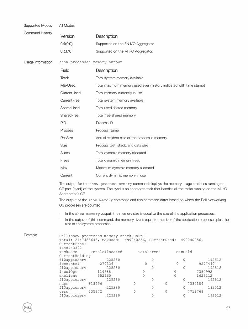
Supported Modes All Modes
Command HistoryVersion Description
9.4(0.0) Supported on the FN I/O Aggregator.
8.3.17.0 Supported on the M I/O Aggregator.
Usage Information show processes memory output
Field Description
Total: Total system memory available
MaxUsed: Total maximum memory used ever (history indicated with time stamp)
CurrentUsed: Total memory currently in use
CurrentFree: Total system memory available
SharedUsed: Total used shared memory
SharedFree: Total free shared memory
PID Process ID
Process Process Name
ResSize Actual resident size of the process in memory
Size Process test, stack, and data size
Allocs Total dynamic memory allocated
Frees Total dynamic memory freed
Max Maximum dynamic memory allocated
Current Current dynamic memory in use
The output for the show process memory command displays the memory usage statistics running on
CP part (sysd) of the system. The sysd is an aggregate task that handles all the tasks running on the M I/O Aggregator’s CP.
The output of the show memory command and this command differ based on which the Dell Networking
OS processes are counted.
• In the show memory output, the memory size is equal to the size of the application processes.
• In the output of this command, the memory size is equal to the size of the application processes plus the size of the system processes.
Example Dell#show processes memory stack-unit 1Total: 2147483648, MaxUsed: 499040256, CurrentUsed: 499040256, CurrentFree:1648443392TaskName TotalAllocated TotalFreed MaxHeld CurrentHoldingf10appioserv 225280 0 0 192512fcoecntrl 270336 0 0 9277440f10appioserv 225280 0 0 192512iscsiOpt 114688 0 0 7380992dhclient 552960 0 0 1626112f10appioserv 225280 0 0 192512ndpm 618496 0 0 7389184f10appioserv 225280 0 0 192512vrrp 335872 0 0 7712768f10appioserv 225280 0 0 192512
67

frrp 180224 0 0 7192576f10appioserv 225280 0 0 192512xstp 2740224 0 0 9445376f10appioserv 225280 0 0 192512pim 1007616 0 0 7585792f10appioserv 225280 0 0 192512igmp 417792 0 0 14774272f10appioserv 225280 0 0 192512mrtm 5496832 0 0 12636160
--More--
Example (management-unit)
Dell#show processes memory management-unitTotal : 2147483648, MaxUsed : 499093504 [07/23/2012 17:42:16]CurrentUsed: 499093504, CurrentFree: 1648390144SharedUsed : 18470440, SharedFree : 2501104
PID Process ResSize Size Allocs Frees Max Current633 fcoecntrl 9277440 270336 1380528 132512 12811441248016289 iscsiOpt 7380992 114688 23262 16564 232626698476 dhclient 1626112 552960 0 0 00521 ndpm 7389184 618496 4848 0 48484848160 vrrp 7712768 335872 880 0 880880318 frrp 7192576 180224 71086 66256 213944830218 xstp 9445376 2740224 21858 0 2185821858277 pim 7585792 1007616 62168 0 6216862168--More--
show revisionDisplays the revision numbers of all stack-units.
Syntax show revisionCommand Modes
• EXEC Privilege
Supported Modes All Modes
Command HistoryVersion Description
9.4(0.0) Supported on the FN I/O Aggregator.
8.3.17.0 Supported on the M I/O Aggregator.
Example (Command)
Dell#show revision-- Stack unit 1 --IOM SYSTEM CPLD : 1Dell#
68

show server-interfacesDisplays server port information.
Syntax show server-interfaces{brief|detail}Command Modes
• EXEC Privilege
Supported Modes All Modes
Command HistoryVersion Description
9.4(0.0) Supported on the FN I/O Aggregator.
8.3.17.0 Supported on the M I/O Aggregator.
Example (brief Command)
Dell#show server-interfaces brief---------------- show server ports brief ---------------------Interface OK Status Protocol DescriptionTenGigabitEthernet 1/1 NO up downTenGigabitEthernet 1/2 NO up downTenGigabitEthernet 1/3 NO up downTenGigabitEthernet 1/4 NO up downTenGigabitEthernet 1/5 YES up upTenGigabitEthernet 1/6 NO up downTenGigabitEthernet 1/7 NO up downTenGigabitEthernet 1/8 NO up downTenGigabitEthernet 1/9 NO up downTenGigabitEthernet 1/10 NO up downTenGigabitEthernet 1/11 NO up downTenGigabitEthernet 1/12 NO up downTenGigabitEthernet 1/13 YES up upTenGigabitEthernet 1/14 NO up downTenGigabitEthernet 1/15 NO up downTenGigabitEthernet 1/16 YES up up--More--Dell#
Example (detail Command)
Dell#show server-interfaces detail---------------- show server ports detail ---------------------TenGigabitEthernet 0/1 is up, line protocol is down(error-disabled[UFD])Hardware is DellForce10Eth, address is 00:1e:c9:f1:00:99Current address is 00:1e:c9:f1:00:99Server Port AdminState is N/APluggable media not presentInterface index is 34149121Internet address is not setMode of IP Address Assignment : NONEDHCP Client-ID :tenG130001ec9f10099MTU 12000 bytes, IP MTU 11982 bytesLineSpeed autoFlowcontrol rx on tx offARP type: ARPA, ARP Timeout 04:00:00Last clearing of "show interface" counters 00:59:19Queueing strategy: fifoInput Statistics:0 packets, 0 bytes0 64-byte pkts, 0 over 64-byte pkts, 0 over 127-byte pkts0 over 255-byte pkts, 0 over 511-byte pkts, 0 over 1023-byte pkts0 Multicasts, 0 Broadcasts0 runts, 0 giants, 0 throttles0 CRC, 0 overrun, 0 discardedOutput Statistics:0 packets, 0 bytes, 0 underruns0 64-byte pkts, 0 over 64-byte pkts, 0 over 127-byte pkts
69

0 over 255-byte pkts, 0 over 511-byte pkts, 0 over 1023-byte pkts0 Multicasts, 0 Broadcasts, 0 Unicasts0 throttles, 0 discarded, 0 collisions, 0 wreddropsRate info (interval 299 seconds):Input 00.00 Mbits/sec, 0 packets/sec, 0.00% of line-rateOutput 00.00 Mbits/sec, 0 packets/sec, 0.00% of line-rateTime since last interface status change: 00:58:08TenGigabitEthernet 0/2 is up, line protocol is down(error-disabled[UFD])Hardware is DellForce10Eth, address is 00:1e:c9:f1:00:99Current address is 00:1e:c9:f1:00:99Server Port AdminState is N/APluggable media not presentInterface index is 34411265Internet address is not setMode of IP Address Assignment : NONEDHCP Client-ID :tenG131001ec9f10099--More--
show systemDisplays the current status of all stack members or a specific stack member.
Syntax show system [brief | stack-unit unit-id]Parameters
brief (OPTIONAL) Enter the keywordbrief to view an abbreviated list of system information.
stack unit unit–id (OPTIONAL) Enter the keywordsstack unit then the stack member ID for information
on the stack member. The range is from 0 to 5.
Command Modes• EXEC
• EXEC Privilege
Supported Modes All Modes
Command HistoryVersion Description
9.4(0.0) Supported on the FN I/O Aggregator.
8.3.17.0 Supported on the M I/O Aggregator.
Example (show system brief command)
Dell#show system briefStack MAC : 00:01:e8:00:ab:03-- Stack Info --Unit UnitType Status ReqTyp CurTyp Version Ports------------------------------------------------------------------------------------0 Member not present1 Management online I/O-Aggregator I/O-Aggregator 8-3-17-38 562 Member not present3 Member not present4 Member not present5 Member not presentDell#
Example (stack-unit command)
Dell#show system stack-unit 1-- Unit 1 --Unit Type : Management UnitStatus : online
70
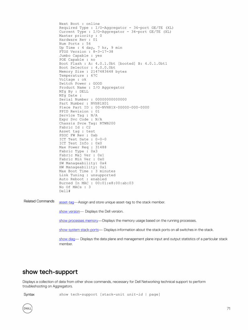
Next Boot : onlineRequired Type : I/O-Aggregator - 34-port GE/TE (XL)Current Type : I/O-Aggregator - 34-port GE/TE (XL)Master priority : 0Hardware Rev : 01Num Ports : 56Up Time : 4 day, 7 hr, 9 minFTOS Version : 8-3-17-38Jumbo Capable : yesPOE Capable : noBoot Flash : A: 4.0.1.0bt [booted] B: 4.0.1.0bt1Boot Selector : 4.0.0.0btMemory Size : 2147483648 bytesTemperature : 67CVoltage : okSwitch Power : GOODProduct Name : I/O AggregatorMfg By : DELLMfg Date :Serial Number : 00000000000000Part Number : NVH81X01Piece Part ID : 00-NVH81X-00000-000-0000PPID Revision : 01Service Tag : N/AExpr Svc Code : N/AChassis Svce Tag: RTWB200Fabric Id : C2Asset tag : testPSOC FW Rev : 0xbICT Test Date : 0-0-0ICT Test Info : 0x0Max Power Req : 31488Fabric Type : 0x3Fabric Maj Ver : 0x1Fabric Min Ver : 0x0SW Manageability: 0x4HW Manageability: 0x1Max Boot Time : 3 minutesLink Tuning : unsupportedAuto Reboot : enabledBurned In MAC : 00:01:e8:00:ab:03No Of MACs : 3Dell#
Related Commands asset-tag—Assign and store unique asset-tag to the stack member.
show version— Displays the Dell version.
show processes memory—Displays the memory usage based on the running processes.
show system stack-ports— Displays information about the stack ports on all switches in the stack.
show diag— Displays the data plane and management plane input and output statistics of a particular stack member.
show tech-supportDisplays a collection of data from other show commands, necessary for Dell Networking technical support to perform troubleshooting on Aggregators.
Syntax show tech-support [stack-unit unit-id | page]
71

Parametersstack-unit (OPTIONAL) Enter the keyword stack-unit to view CPU memory usage for the
stack member designated by unit-id. The range is 0 to 5.
page (OPTIONAL) Enter the keyword page to view 24 lines of text at a time. Press the
SPACE BAR to view the next 24 lines. Press the ENTER key to view the next line of text.
When using the pipe command ( | ), enter one of these keywords to filter command output. Refer to CLI Basics for details on filtering commands.
save Enter the keyword save to save the command output.
flash: Save to local flash drive (flash://filename (max 20 chars))
Command Modes• EXEC Privilege
Supported Modes All Modes
Command HistoryVersion Description
9.4(0.0) Supported on the FN I/O Aggregator.
8.3.17.0 Supported on the M I/O Aggregator.
Usage Information Without the page or stack-unit option, the command output is continuous, use Ctrl-z to interrupt the
command output.
The save option works with other filtering commands. This allows you to save specific information of a
show command. The save entry must always be the last option.
For example: Dell#show tech-support |grep regular-expression |except regular-expression | find regular-expression | save flash://result
This display output is an accumulation of the same information that is displayed when you execute one of the following showcommands:
• show cam• show clock• show environment• show file• show interfaces• show inventory• show processes cpu• show processes memory• show running-conf• show version
Example (save) Dell#show tech-support ?page Page through outputstack-unit Unit Number| Pipe through a command<cr>Dell#show tech-support stack-unit 1 ?page Page through output
72

| Pipe through a command<cr>Dell#show tech-support stack-unit 1 | ?except S how only text that does not match a patternfind Search for the first occurrence of a patterngrep Show only text that matches a patternno-more Don't paginate outputsave Save output to a fileDell#show tech-support stack-unit 1 | save ?flash: Save to local file system (flash://filename (max 20 chars) )usbflash: Save to local file system (usbflash://filename (max 20chars) )Dell#show tech-support stack-unit 1 | save flash://LauraSaveStart saving show command report .......Dell#Dell#dirDirectory of flash:Directory of flash:1 drwx 4096 Jan 01 1980 01:00:00 +01:00 .2 drwx 2048 May 16 2012 10:49:01 +01:00 ..3 drwx 4096 Jan 24 2012 19:38:32 +01:00 TRACE_LOG_DIR4 drwx 4096 Jan 24 2012 19:38:32 +01:00 CORE_DUMP_DIR5 d--- 4096 Jan 24 2012 19:38:34 +01:00 ADMIN_DIR6 -rwx 10303 Mar 15 2012 18:37:20 +01:00 startup-config.bak7 -rwx 7366 Apr 20 2012 10:57:02 +01:00 startup-config8 -rwx 4 Feb 19 2012 07:05:02 +01:00 dhcpBindConflict9 -rwx 12829 Feb 18 2012 02:24:14 +01:00 startup-config.backup10 drwx 4096 Mar 08 2012 22:58:54 +01:00 WJ_running-config11 -rwx 7689 Feb 21 2012 04:45:40 +01:00 stbkupflash: 2143281152 bytes total (2131476480 bytes free)Dell
Example (support) Dell#show tech-support stack-unit 1----------------------------------- show version -------------------------------Dell Networking Real Time Operating System SoftwareDell Networking Operating System Version: 1.0Dell Networking Application Software Version: E8-3-17-38Copyright (c) 1999-2012 by Dell Inc. All Rights Reserved.Build Time: Thu Jul 19 05:59:59 PDT 2012Build Path: /sites/sjc/work/swsystems01-2/ravisubramani/ravis-8317/SW/SRC/Cp_src/TacacsFTOS uptime is 4 day(s), 7 hour(s), 14 minute(s)System image file is "dv-m1000e-2-b2"System Type: I/O-AggregatorControl Processor: MIPS RMI XLP with 2147483648 bytes of memory.256M bytes of boot flash memory.1 34-port GE/TE (XL)56 Ten GigabitEthernet/IEEE 802.3 interface(s)------------------------------------ show clock -------------------------------17:49:37.2 UTC Mon Jul 23 2012----------------------------------- show running-config ------------------------Current Configuration ...! Version E8-3-17-38! Last configuration change at Mon Jul 23 17:10:18 2012 by default!boot system stack-unit 1 primary tftp://10.11.9.21/dv-m1000e-2-b2boot system stack-unit 1 default system: A:boot system gateway 10.11.209.62!redundancy auto-synchronize full!service timestamps log datetime!hostname FTOS
73

----------------------------------- show ip management route -------------------Destination Gateway State----------- ------- -----1--More--Dell#
Related Commands show version — displays the Dell Networking OS version.
show system — displays the current switch status..
show environment — displays system component status.
show processes memory — displays memory usage based on the running processes.
show uplink briefDisplays the uplink port information.
Syntax show uplink {brief|detail}Parameters
brief Enter the keyword brief to display a brief summary of the uplink port information.
detail Enter the keyword detail to display uplink port information with description.
Command Modes• EXEC Privilege
Supported Modes All Modes
Command HistoryVersion Description
9.4(0.0) Supported on the FN I/O Aggregator.
8.3.17.0 Supported on the M I/O Aggregator.
Example (brief) Dell#show uplink brief---------------- show uplink brief ---------------------Interface OK Status Protocol DescriptionTenGigabitEthernet 0/41 NO up downTenGigabitEthernet 0/43 NO up downTenGigabitEthernet 0/44 NO up downTenGigabitEthernet 0/45 NO up downTenGigabitEthernet 0/46 NO up downTenGigabitEthernet 0/47 NO up downTenGigabitEthernet 0/48 NO up downTenGigabitEthernet 0/49 NO up downTenGigabitEthernet 0/50 NO up downTenGigabitEthernet 0/51 NO up downTenGigabitEthernet 0/52 NO up downTenGigabitEthernet 0/53 NO up downTenGigabitEthernet 0/54 NO up downTenGigabitEthernet 0/55 NO up downTenGigabitEthernet 0/56 NO up downTenGigabitEthernet 1/41 NO up downTenGigabitEthernet 1/42 NO up downTenGigabitEthernet 1/43 NO up down
74

--More--4 www.force10networks.com (10.11.84.18) 000.000 ms 000.000 ms 000.000 msDell#
Example (detail) Dell#show uplink detail---------------- show uplink detail ---------------------TenGigabitEthernet 0/41 is up, line protocol is downHardware is DellForce10Eth, address is 00:1e:c9:f1:00:99Current address is 00:1e:c9:f1:00:99Port is not prsentPluggable media not presentInterface index is 44634881Internet address is not setMode of IP Address Assignment : NONEDHCP Client-ID :tenG170001ec9f10099MTU 12000 bytes, IP MTU 11982 bytesLineSpeed autoFlowcontrol rx on tx offARP type: ARPA, ARP Timeout 04:00:00Last clearing of "show interface" counters 2d19h53mQueueing strategy: fifoInput Statistics:0 packets, 0 bytes0 64-byte pkts, 0 over 64-byte pkts, 0 over 127-byte pkts0 over 255-byte pkts, 0 over 511-byte pkts, 0 over 1023-byte pkts0 Multicasts, 0 Broadcasts--More--
show util-threshold cpuDisplays the set CPU utilization threshold values.
Syntax show util-threshold cpuCommand Modes
• EXEC Privilege
Supported Modes All Modes
Command HistoryVersion Description
9.4(0.0) Supported on the FN I/O Aggregator.
8.3.17.0 Supported on the M I/O Aggregator.
Usage Information This command displays all CPU utilization thresholds of the management, standby, and stack-units.
show util-threshold memoryDisplays the set memory utilization threshold values.
Syntax show util-threshold memoryCommand Modes
• EXEC Privilege
75

Supported Modes All Modes
Command HistoryVersion Description
9.4(0.0) Supported on the FN I/O Aggregator.
8.3.17.0 Supported on the M I/O Aggregator.
Usage Information This command displays all memory utilization thresholds of the management, standby, and stack-units.
ssh-peer-stack-unitOpen an SSH connection to the peer stack-unit.
Syntax ssh-peer-stack-unit [-| username]Parameters
-| username (OPTIONAL) Enter the keyword -| followed by your username.
Default: The username associated with the terminal.
Defaults Not configured.
Command Modes• EXEC Privilege
Supported Modes All Modes
Command HistoryVersion Description
9.6(0.0) Supported on the FN I/O Aggregator.
8.3.17.0 Supported on the M I/O Aggregator.
telnetConnect through Telnet to a server. The Telnet client and server in Dell Networking OS support IPv4 connections. You can establish a Telnet session directly to the router or a connection can be initiated from the router.
Syntax telnet {host | ip-address [/source-interface]Parameters
host Enter the name of a server.
ip-address Enter the IPv4 address in dotted decimal format of the server.
source-interface (OPTIONAL) Enter the keywords /source-interface then the interface
information to include the source interface. Enter the following keywords and slot/port or number information:
• For a 10-Gigabit Ethernet interface, enter the keyword TenGigabitEthernet then the slot/port information.
76

• For a VLAN interface, enter the keyword vlan then a number from 1 to 4094.
Defaults Not configured.
Command Modes• EXEC
• EXEC Privilege
Supported Modes All Modes
Command HistoryVersion Description
9.4(0.0) Supported on the FN I/O Aggregator.
8.3.17.0 Supported on the M I/O Aggregator.
Usage Information Telnet to link-local addresses is not supported.
telnet-peer-stack-unitOpen a telnet connection to the peer stack-unit.
Syntax telnet-peer-stack-unitDefaults Not configured.
Command Modes• EXEC Privilege
Supported Modes All Modes
Command HistoryVersion Description
9.6.(0.0) Supported on the FN I/O Aggregator.
8.3.17.0 Supported on the M I/O Aggregator.
terminal lengthConfigure the number of lines displayed on the terminal screen.
Syntax terminal length screen-lengthTo return to the default values, use the no terminal length command.
Parametersscreen-length Enter a number of lines. Entering zero will cause the terminal to display without
pausing. The range is from 0 to 512.
Default: 24 lines
77

Defaults 24 lines
Command Modes• EXEC
• EXEC Privilege
Supported Modes All Modes
Command HistoryVersion Description
9.4(0.0) Supported on the FN I/O Aggregator.
8.3.17.0 Supported on the M I/O Aggregator.
terminal monitorConfigure the Dell Networking OS to display messages on the monitor/terminal.
Syntax terminal monitorTo return to default settings, use the no terminal monitor command.
Defaults Disabled
Command Modes• EXEC
• EXEC Privilege
Supported Modes All Modes
Command HistoryVersion Description
9.4(0.0) Supported on the FN I/O Aggregator.
8.3.17.0 Supported on the M I/O Aggregator.
terminal xmlEnable XML mode in Telnet and SSH client sessions.
Syntax terminal xmlTo exit the XML mode, use the no terminal monitor command.
Defaults Disabled
Command Modes• EXEC
• EXEC Privilege
Supported Modes All Modes
78
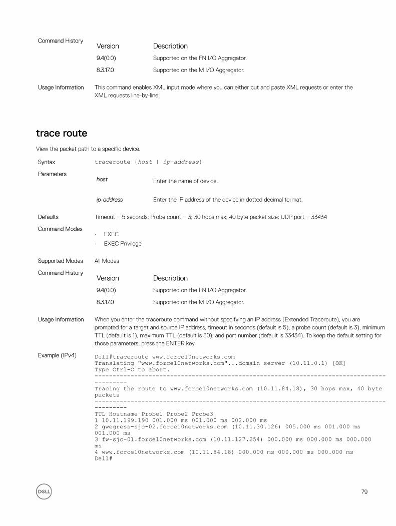
Command HistoryVersion Description
9.4(0.0) Supported on the FN I/O Aggregator.
8.3.17.0 Supported on the M I/O Aggregator.
Usage Information This command enables XML input mode where you can either cut and paste XML requests or enter the XML requests line-by-line.
trace routeView the packet path to a specific device.
Syntax traceroute {host | ip-address}Parameters
host Enter the name of device.
ip-address Enter the IP address of the device in dotted decimal format.
Defaults Timeout = 5 seconds; Probe count = 3; 30 hops max; 40 byte packet size; UDP port = 33434
Command Modes• EXEC
• EXEC Privilege
Supported Modes All Modes
Command HistoryVersion Description
9.4(0.0) Supported on the FN I/O Aggregator.
8.3.17.0 Supported on the M I/O Aggregator.
Usage Information When you enter the traceroute command without specifying an IP address (Extended Traceroute), you are prompted for a target and source IP address, timeout in seconds (default is 5), a probe count (default is 3), minimum TTL (default is 1), maximum TTL (default is 30), and port number (default is 33434). To keep the default setting for those parameters, press the ENTER key.
Example (IPv4) Dell#traceroute www.force10networks.comTranslating "www.force10networks.com"...domain server (10.11.0.1) [OK]Type Ctrl-C to abort.------------------------------------------------------------------------------------------Tracing the route to www.force10networks.com (10.11.84.18), 30 hops max, 40 bytepackets------------------------------------------------------------------------------------------TTL Hostname Probe1 Probe2 Probe31 10.11.199.190 001.000 ms 001.000 ms 002.000 ms2 gwegress-sjc-02.force10networks.com (10.11.30.126) 005.000 ms 001.000 ms001.000 ms3 fw-sjc-01.force10networks.com (10.11.127.254) 000.000 ms 000.000 ms 000.000ms4 www.force10networks.com (10.11.84.18) 000.000 ms 000.000 ms 000.000 msDell#
79

Related Commands ping — Tests the connectivity to a device.
undebug allDisable all debug operations on the system.
Syntax undebug allDefaults none
Command Modes• EXEC Privilege
Supported Modes All Modes
Command HistoryVersion Description
9.4(0.0) Supported on the FN I/O Aggregator.
8.3.17.0 Supported on the M I/O Aggregator.
writeCopy the current configuration to either the startup-configuration file or the terminal.
Syntax write {memory | terminal}Parameters
memory Enter the keyword memory to copy the current running configuration to the
startup configuration file. This command is similar to the copy running-config startup-config command.
terminal Enter the keyword terminal to copy the current running configuration to the
terminal. This command is similar to the show running-configcommand.
Command Modes• EXEC Privilege
Supported Modes All Modes
Command HistoryVersion Description
9.4(0.0) Supported on the FN I/O Aggregator.
8.3.17.0 Supported on the M I/O Aggregator.
Usage Information The write memory command saves the running-configuration to the file labeled startup-configuration.
When using a LOCAL CONFIG FILE other than the startup-config not named “startup-configuration”, the running-config is not saved to that file; use the copy command to save any running-configuration changes
to that local file.
80

6u-BootAll commands in this chapter are in u-Boot mode. These commands are supported on the Dell Networking Aggregator only.
To access this mode, hit any key when the following line appears on the console during a system boot: Hit any key to stop autoboot:
You enter u-Boot immediately, as indicated by the BOOT_USER# prompt.
NOTE: Only the most frequently used commands available in uBoot mode are described in this chapter.
In uBoot mode, you cannot use the Tab key for command completion.
boot changeChange the operating system boot parameters.
Syntax boot change [primary | secondary | default]Command Modes uBoot
Supported Modes All Modes
Command HistoryVersion Description
9.4(0.0) Supported on the FN I/O Aggregator.
8.3.17.0 Supported on the M I/O Aggregator.
boot show net config retriesShow the number of retries for network boot configuration failure.
Syntax boot show net config retriesCommand Modes uBoot
Supported Modes All Modes
Command HistoryVersion Description
9.4(0.0) Supported on the FN I/O Aggregator.
8.3.17.0 Supported on the M I/O Aggregator.
81

Example BOOT_USER# boot show net config retriesNumber of Network Boot Config Retries is : 0BOOT_USER #
boot write net config retriesSet the number of retries for network boot configuration failure.
Syntax boot write net config retries <int>Command Modes uBoot
Supported Modes All Modes
Command HistoryVersion Description
9.4(0.0) Supported on the FN I/O Aggregator.
8.3.17.0 Supported on the M I/O Aggregator.
Example BOOT_USER # boot write net config retries 2Updated number of Network Boot Config retries to 2.BOOT_USER #
boot zeroClears the primary, secondary, or default boot parameters.
Syntax boot zero [primary| secondary| default]Command Modes uBoot
Supported Modes All Modes
Command HistoryVersion Description
9.4(0.0) Supported on the FN I/O Aggregator.
8.3.17.0 Supported on the M I/O Aggregator.
default gatewaySet the default gateway IP address.
Syntax default-gateway <ip-address>Command Modes uBoot
Supported Modes All Modes
82
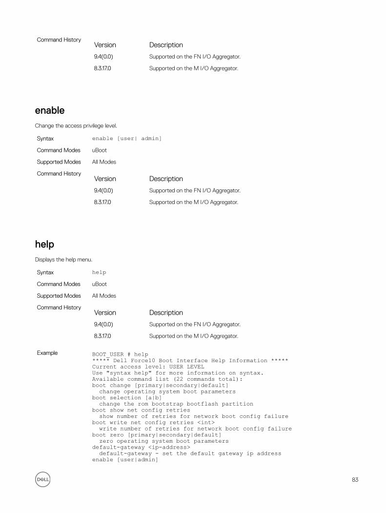
Command HistoryVersion Description
9.4(0.0) Supported on the FN I/O Aggregator.
8.3.17.0 Supported on the M I/O Aggregator.
enableChange the access privilege level.
Syntax enable [user| admin]Command Modes uBoot
Supported Modes All Modes
Command HistoryVersion Description
9.4(0.0) Supported on the FN I/O Aggregator.
8.3.17.0 Supported on the M I/O Aggregator.
helpDisplays the help menu.
Syntax helpCommand Modes uBoot
Supported Modes All Modes
Command HistoryVersion Description
9.4(0.0) Supported on the FN I/O Aggregator.
8.3.17.0 Supported on the M I/O Aggregator.
Example BOOT_USER # help***** Dell Force10 Boot Interface Help Information *****Current access level: USER LEVELUse "syntax help" for more information on syntax.Available command list (22 commands total):boot change [primary|secondary|default] change operating system boot parametersboot selection [a|b] change the rom bootstrap bootflash partitionboot show net config retries show number of retries for network boot config failureboot write net config retries <int> write number of retries for network boot config failureboot zero [primary|secondary|default] zero operating system boot parametersdefault-gateway <ip-address> default-gateway - set the default gateway ip addressenable [user|admin]
83

change access privilege levelhelp display help menu-(36%)-Use <CR> to continue, q to stop:BOOT_USER #
ignore enable passwordIgnore the enabled password.
Syntax ignore enable-passwordCommand Modes uBoot
Supported Modes All Modes
Command HistoryVersion Description
9.4(0.0) Supported on the FN I/O Aggregator.
8.3.17.0 Supported on the M I/O Aggregator.
ignore startup-configIgnore the system startup configuration.
Syntax ignore startup-configCommand Modes uBoot
Supported Modes All Modes
Command HistoryVersion Description
9.4(0.0) Supported on the FN I/O Aggregator.
8.3.17.0 Supported on the M I/O Aggregator.
interface management ethernet ip addressSet the management port IP address and mask.
Syntax interface management ethernet ip address <ip/mask>Command Modes uBoot
Supported Modes All Modes
Command HistoryVersion Description
9.4(0.0) Supported on the FN I/O Aggregator.
84
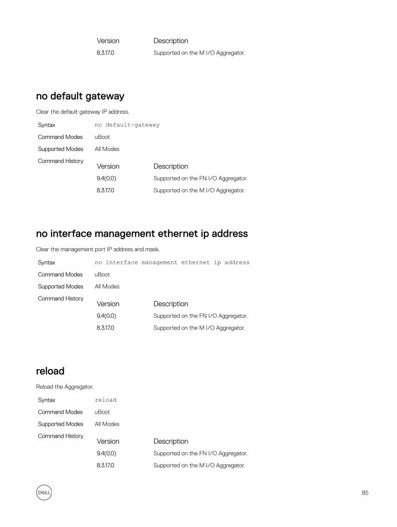
Version Description
8.3.17.0 Supported on the M I/O Aggregator.
no default gatewayClear the default gateway IP address.
Syntax no default-gatewayCommand Modes uBoot
Supported Modes All Modes
Command HistoryVersion Description
9.4(0.0) Supported on the FN I/O Aggregator.
8.3.17.0 Supported on the M I/O Aggregator.
no interface management ethernet ip addressClear the management port IP address and mask.
Syntax no interface management ethernet ip addressCommand Modes uBoot
Supported Modes All Modes
Command HistoryVersion Description
9.4(0.0) Supported on the FN I/O Aggregator.
8.3.17.0 Supported on the M I/O Aggregator.
reloadReload the Aggregator.
Syntax reloadCommand Modes uBoot
Supported Modes All Modes
Command HistoryVersion Description
9.4(0.0) Supported on the FN I/O Aggregator.
8.3.17.0 Supported on the M I/O Aggregator.
85

show boot blcShow the boot loop counter value.
Syntax show boot blcCommand Modes uBoot
Supported Modes All Modes
Command HistoryVersion Description
9.4(0.0) Supported on the FN I/O Aggregator.
8.3.17.0 Supported on the M I/O Aggregator.
Example BOOT_USER # show boot blc ?Total 1 possible command found.Possible command list:show boot blc show the boot loop counter valueBOOT_USER # show boot blcBoot Loop Counter : 10
BOOT_USER #
show boot selectionDisplays the ROM bootstrap bootflash partition.
Syntax show boot selectionCommand Modes uBoot
Supported Modes All Modes
Command HistoryVersion Description
9.4(0.0) Supported on the FN I/O Aggregator.
8.3.17.0 Supported on the M I/O Aggregator.
Example BOOT_USER # show boot blc ?Total 1 possible command found.Possible command list:show boot blc show the boot loop counter valueBOOT_USER # show boot blcBoot Loop Counter : 10
BOOT_USER #
86

show bootflashShow the summary of boot flash information.
Syntax show bootflashCommand Modes uBoot
Supported Modes All Modes
Command HistoryVersion Description
9.4(0.0) Supported on the FN I/O Aggregator.
8.3.17.0 Supported on the M I/O Aggregator.
Example BOOT_USER # show bootflash
GENERAL BOOTFLASH INFO======================Bootflash Partition A: Dell Force10 Networks System Boot Official IOM_LP_IMG_BOOT_LOADER, BSP Release 4.0.1.0bt1 Created Tue May 1 10:56:16 2012 by build on login-sjc-01
Bootflash Partition B: Dell Force10 Networks System Boot Official IOM_LP_IMG_BOOT_LOADER, BSP Release 4.0.1.0bt1 Created Tue May 1 10:56:16 2012 by build on login-sjc-01
Boot Selector Partition: Dell Force10 Networks System Boot Official IOM_XLOAD_LP_IMG_BOOT_SELECTOR, BSP Release 4.0.0.0bt1 Created Tue May 1 10:56:34 2012 by build on login-sjc-01
BOOT_USER #
show bootvarShow the summary of operating system boot parameters.
Syntax show bootvarCommand Modes uBoot
Supported Modes All Modes
Command HistoryVersion Description
9.4(0.0) Supported on the FN I/O Aggregator.
8.3.17.0 Supported on the M I/O Aggregator.
Example BOOT_USER # show bootvar
PRIMARY OPERATING SYSTEM BOOT PARAMETERS:========================================boot device : tftpfile name : premnathManagement Etherenet IP address : 10.16.130.134/16Server IP address : 10.16.127.35
87

Default Gateway IP address : 15.0.0.1Management Etherenet MAC address : 00:01:E8:43:DE:DF
SECONDARY OPERATING SYSTEM BOOT PARAMETERS:========================================No Operating System boot parameters specified!
DEFAULT OPERATING SYSTEM BOOT PARAMETERS:========================================boot device : tftpfile name : FTOS-XL-8-3-16-99.binManagement Etherenet IP address : 10.16.130.134/16Server IP address : 10.16.127.53Default Gateway IP address : 15.0.0.1Management Etherenet MAC address : 00:01:E8:43:DE:DF
BOOT_USER #
show default gatewayDisplays the default gateway IP address.
Syntax show default-gatewayCommand Modes uBoot
Supported Modes All Modes
Command HistoryVersion Description
9.4(0.0) Supported on the FN I/O Aggregator.
8.3.17.0 Supported on the M I/O Aggregator.
Example BOOT_USER # show default-gatewayGateway IP address: 15.0.0.1BOOT_USER #
show interface management ethernetShow the management port IP address and mask.
Syntax show interface management ethernetCommand Modes uBoot
Supported Modes All Modes
Command HistoryVersion Description
9.4(0.0) Supported on the FN I/O Aggregator.
8.3.17.0 Supported on the M I/O Aggregator.
88

Example BOOT_USER # show interface management ethernetManagement ethernet IP address: 10.16.130.134/16BOOT_USER #
show interface management port configShow the management port boot characteristics.
Syntax show interface management port configCommand Modes uBoot
Supported Modes All Modes
Command HistoryVersion Description
9.4(0.0) Supported on the FN I/O Aggregator.
8.3.17.0 Supported on the M I/O Aggregator.
Example BOOT_USER # show interface management port configManagement ethernet Port Configuration: no Auto NegotiateManagement ethernet Port Configuration: 100MManagement ethernet Port Configuration: full duplexBOOT_USER #
syntax helpShow the syntax information.
Syntax helpCommand Modes uBoot
Supported Modes All Modes
Command HistoryVersion Description
9.4(0.0) Supported on the FN I/O Aggregator.
8.3.17.0 Supported on the M I/O Aggregator.
89

7Data Center Bridging (DCB)Data center bridging (DCB) refers to a set of IEEE Ethernet enhancements that provide data centers with a single, robust, converged network to support multiple traffic types, including local area network (LAN), server, and storage traffic. DCB features are auto-configured in standalone mode.
The Dell Networking OS commands for DCB features include 802.1Qbb priority-based flow control (PFC), 802.1Qaz enhanced transmission selection (ETS), and the data center bridging exchange (DCBX) protocol.
CLI commands for individual DCB features are as follows:
DCB command
• dcb enable auto-detect on-next-reload
• show qos dcb-map
PFC Commands
• clear pfc counters
• show interface pfc
• show interface pfc statistics
ETS Commands
• clear ets counters
• show interface ets
DCBX Commands
• dcbx version
• clear dcbx counters
• show dcb
• show interface dcbx detail
advertise dcbx-appln-tlvOn a DCBX port with a manual role, configure the application priority TLVs advertised on the interface to DCBX peers.
Syntax advertise dcbx-appln-tlv {fcoe | iscsi}To remove the application priority TLVs, use the no advertise dcbx-appln-tlv {fcoe | iscsi} command.
Parameters{fcoe | iscsi} Enter the application priority TLVs, where:
• fcoe: enables the advertisement of FCoE in application priority TLVs.
90

• iscsi: enables the advertisement of iSCSI in application priority TLVs.
Defaults Application priority TLVs are enabled to advertise FCoE and iSCSI.
Command Modes PROTOCOL LLDP
Supported Modes Programmable-Mux (PMUX)
Command HistoryVersion Description
9.4(0.0) Supported on the FN I/O Aggregator.
9.2(0.0) Introduced on the M I/O Aggregator.
8.3.16.1 Introduced on the MXL 10/40GbE Switch IO Module.
Usage Information To disable TLV transmission, use the no form of the command; for example, no advertise dcbx-appln-tlv iscsi.
advertise dcbx-tlvOn a DCBX port with a manual role, configure the PFC and ETS TLVs advertised to DCBX peers.
Syntax advertise dcbx-tlv {ets-conf | ets-reco | pfc} [ets-conf | ets-reco | pfc] [ets-conf | ets-reco | pfc]To remove the advertised ETS TLVs, use the no advertise dcbx-tlv command.
Parameters{ets-conf | ets-reco | pfc}
Enter the PFC and ETS TLVs advertised, where:
• ets-conf: enables the advertisement of ETS configuration TLVs.
• ets-reco: enables the advertisement of ETS recommend TLVs.
• pfc: enables the advertisement of PFC TLVs.
Defaults All PFC and ETS TLVs are advertised.
Command Modes PROTOCOL LLDP
Supported Modes Programmable-Mux (PMUX)
Command HistoryVersion Description
9.4(0.0) Supported on the FN I/O Aggregator.
9.2(0.0) Introduced on the M I/O Aggregator.
8.3.16.1 Introduced on the MXL 10/40GbE Switch IO Module.
Usage Information You can configure the transmission of more than one TLV type at a time; for example: advertise dcbx-tlv ets-conf ets-reco.
You can enable ETS recommend TLVs (ets-reco) only if you enable ETS configuration TLVs (ets-conf). To disable TLV transmission, use the no form of the command; for example, no advertise dcbx-tlv pfc ets-reco.
91

DCBX requires that you enable LLDP to advertise DCBX TLVs to peers.
Configure DCBX operation at the INTERFACE level on a switch or globally on the switch. To verify the DCBX configuration on a port, use the show interface dcbx detail command.
bandwidth-percentageAssign a percentage of weight to the class/queue.
Syntax bandwidth-percentage percentageTo remove the bandwidth percentage, use the no bandwidth-percentage command.
Parameterspercentage Enter the percentage assignment of weight to the class/queue. The range is from 1
to 100% (granularity 1%).
Defaults none
Command Modes CONFIGURATION (conf-qos-policy-out)
Supported Modes Programmable-Mux (PMUX)
Command HistoryVersion Description
9.4(0.0) Supported on the FN I/O Aggregator.
9.2(0.0) Introduced on the M I/O Aggregator.
8.3.16.1 Introduced on the MXL 10/40GbE Switch IO Module.
Usage Information The unit of bandwidth percentage is 1%. A bandwidth percentage of 0 is allowed and disables the scheduling of that class. If the sum of the bandwidth percentages given to all eight classes exceeds 100%, the bandwidth percentage automatically scales down to 100%.
Related Commands qos-policy-output — creates a QoS output policy.
clear dcbx countersClear all DCBx TLV counters on an interface.
Syntax clear dcbx counters tengigabitethernet slot/portDefaults none
Command Modes EXEC Privilege
Supported Modes All Modes
Command HistoryVersion Description
9.4(0.0) Supported on the FN I/O Aggregator.
92
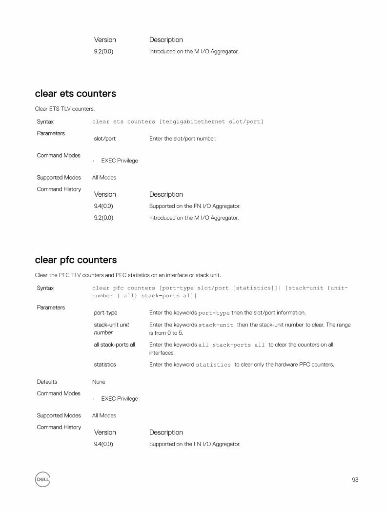
Version Description
9.2(0.0) Introduced on the M I/O Aggregator.
clear ets countersClear ETS TLV counters.
Syntax clear ets counters [tengigabitethernet slot/port]Parameters
slot/port Enter the slot/port number.
Command Modes• EXEC Privilege
Supported Modes All Modes
Command HistoryVersion Description
9.4(0.0) Supported on the FN I/O Aggregator.
9.2(0.0) Introduced on the M I/O Aggregator.
clear pfc countersClear the PFC TLV counters and PFC statistics on an interface or stack unit.
Syntax clear pfc counters [port-type slot/port [statistics]]| [stack-unit {unit-number | all} stack-ports all]
Parametersport-type Enter the keywords port-type then the slot/port information.
stack-unit unit number
Enter the keywords stack-unit then the stack-unit number to clear. The range
is from 0 to 5.
all stack-ports all Enter the keywords all stack-ports all to clear the counters on all
interfaces.
statistics Enter the keyword statistics to clear only the hardware PFC counters.
Defaults None
Command Modes• EXEC Privilege
Supported Modes All Modes
Command HistoryVersion Description
9.4(0.0) Supported on the FN I/O Aggregator.
93
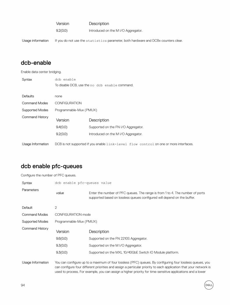
Version Description
9.2(0.0) Introduced on the M I/O Aggregator.
Usage information If you do not use the statistics parameter, both hardware and DCBx counters clear.
dcb-enableEnable data center bridging.
Syntax dcb enableTo disable DCB, use the no dcb enable command.
Defaults none
Command Modes CONFIGURATION
Supported Modes Programmable-Mux (PMUX)
Command HistoryVersion Description
9.4(0.0) Supported on the FN I/O Aggregator.
9.2(0.0) Introduced on the M I/O Aggregator.
Usage Information DCB is not supported if you enable link-level flow control on one or more interfaces.
dcb enable pfc-queuesConfigure the number of PFC queues.
Syntax dcb enable pfc-queues valueParameters
value Enter the number of PFC queues. The range is from 1 to 4. The number of ports supported based on lossless queues configured will depend on the buffer.
Default 2
Command Modes CONFIGURATION mode
Supported Modes Programmable-Mux (PMUX)
Command HistoryVersion Description
9.6(0.0) Supported on the FN 2210S Aggregator.
9.3(0.0) Supported on the M I/O Aggregator.
9.3(0.0) Supported on the MXL 10/40GbE Switch IO Module platform.
Usage Information You can configure up to a maximum of four lossless (PFC) queues. By configuring four lossless queues, you can configure four different priorities and assign a particular priority to each application that your network is used to process. For example, you can assign a higher priority for time-sensitive applications and a lower
94

priority for other services, such as file transfers. You can configure the amount of buffer space to be allocated for each priority and the pause or resume thresholds for the buffer. This method of configuration enables you to effectively manage and administer the behavior of lossless queues.
Example Dell(conf)#dcb pfc-queues 4
dcb enable auto-detect on-next-reloadEnables or disables global DCB on a subsequent reload. This command also internally configures PFC buffers based on DCB enable/disable. Save and reload is mandatory for the configurations to take effect. Auto-detect keyword can be used to re-enable IOA with port wise DCB auto detect feature.
Syntax dcb enable [auto-detect | on-next-reload]To disable global DCB on a subsequent reload, use the no dcb enable on-next-reload command.
Parametersauto-detect Enter the keywords auto-detect to re-enable the Aggregator with port wise DCB auto
detect feature.
on-next-reload Enter the keywords on-next-reload to apply DCB configurations on subsequent reload.
Defaults DCB is globally enabled with auto-detect feature.
Command Modes• CONFIGURATION
Supported Modes All Modes
Command HistoryVersion Description
9.4(0.0) Supported on the FN I/O Aggregator.
8.3.17.3 Added auto-detect parameter on the M I/O Aggregator.
8.3.17.0 Supported on the M I/O Aggregator.
Example (Disable) Dell#show dcb stack-unit 0 port-set 0stack-unit 0 port-set 0DCB Status: Enabled, PFC Queue Count: 4
stack-unit Total Buffer PFC Total Buffer PFC Shared Buffer PFC Available Buffer PP (KB) (KB) (KB) (KB)----------------------------------------------------------------------------------0 0 3822 1912 832 450 Dell(conf)#Dell#Dell#Dell#confDell(conf)#no dcb enable on-next-reloadDell(conf)#endDell#Dell#write memory!Mar 18 00:21:49: %STKUNIT0-M:CP %FILEMGR-5-FILESAVED: Copied running-config to startup-config in flash by default
Dell#reload
95

Proceed with reload [confirm yes/no]: ysyncing disks... doneunmounting file systems...unmounting /f10/flash (/dev/ld0e)...unmounting /usr (mfs:35)...unmounting /lib (mfs:24)...unmounting /f10 (mfs:21)...unmounting /tmp (mfs:15)...unmounting /kern (kernfs)...unmounting / (/dev/md0a)... done rebooting...
Dell#show dcb stack-unit 0 port-set 0stack-unit 0 port-set 0DCB Status: Enabled, PFC Queue Count: 4
stack-unit Total Buffer PFC Total Buffer PFC Shared Buffer PFC Available Buffer PP (KB) (KB) (KB) (KB)----------------------------------------------------------------------------------0 0 3822 1912 832 450 Dell(conf)#Dell#
Example (Enable) Dell#show dcb stack-unit 0 port-set 0stack-unit 0 port-set 0DCB Status: Enabled, PFC Queue Count: 4
stack-unit Total Buffer PFC Total Buffer PFC Shared Buffer PFC Available Buffer PP (KB) (KB) (KB) (KB)----------------------------------------------------------------------------------0 0 3822 1912 832 450 Dell(conf)#Dell#Dell#Dell#Dell#confDell(conf)#dcb enable on-next-reloadDell(conf)#endDell#Mar 18 00:26:07: %STKUNIT0-M:CP %SYS-5-CONFIG_I: Configured from console
Dell#write memory!Mar 18 00:26:11: %STKUNIT0-M:CP %FILEMGR-5-FILESAVED: Copied running-config to startup-config in flash by default
Dell#Dell#reload
Proceed with reload [confirm yes/no]: ysyncing disks... doneunmounting file systems...unmounting /f10/flash (/dev/ld0e)...unmounting /usr (mfs:35)...unmounting /lib (mfs:24)...unmounting /f10 (mfs:21)...unmounting /tmp (mfs:15)...unmounting /kern (kernfs)...unmounting / (/dev/md0a)... donerebooting...Dell#show dcb stack-unit 0 port-set 0stack-unit 0 port-set 0DCB Status: Enabled, PFC Queue Count: 4
stack-unit Total Buffer PFC Total Buffer PFC Shared Buffer PFC Available Buffer PP (KB) (KB) (KB) (KB)----------------------------------------------------------------------------------
96

0 0 3822 1912 832 450 Dell(conf)#
Example (Enable DCB with Auto-Detect)
Dell#show dcb stack-unit 0 port-set 0DCB Status : DisabledPFC Queue Count : 2Total Buffer[lossy + lossless] (in KB) : 3822PFC Total Buffer (in KB) : 1912PFC Shared Buffer (in KB) : 832PFC Available Buffer (in KB) : 1080Dell#Dell#Dell#conDell(conf)#dcb enable auto-detect on-next-reloadDell(conf)#endDell#Mar 18 00:35:19: %STKUNIT0-M:CP %SYS-5-CONFIG_I: Configured from console
Dell#write memory!Mar 18 00:35:24: %STKUNIT0-M:CP %FILEMGR-5-FILESAVED: Copied running-config to startup-config in flash by default
Dell#Dell#reload
Proceed with reload [confirm yes/no]: ysyncing disks... doneunmounting file systems...unmounting /f10/flash (/dev/ld0e)...unmounting /usr (mfs:35)...unmounting /lib (mfs:24)...unmounting /f10 (mfs:21)...unmounting /tmp (mfs:15)...unmounting /kern (kernfs)...unmounting / (/dev/md0a)... done rebooting...Dell#show dcb stack-unit 0 port-set 0stack-unit 0 port-set 0DCB Status: Enabled, PFC Queue Count: 4
stack-unit Total Buffer PFC Total Buffer PFC Shared Buffer PFC Available Buffer PP (KB) (KB) (KB) (KB)----------------------------------------------------------------------------------0 0 3822 1912 832 450 Dell(conf)#
dcb-map stack-unit all stack-ports allApply the specified DCB map on all ports of the switch stack.
Syntax dcb-map stack-unit all stack-ports all dcb-map-nameTo remove the PFC and ETS settings in a DCB map from all stack units, use the no dcb-map stack-unit all stack-ports all command.
Parametersdcb-map-name Enter the name of the DCB map.
Defaults None
97

Command Modes CONFIGURATION
Supported Modes Programmable-Mux (PMUX)
Command HistoryVersion Description
9.4(0.0) Supported on the FN I/O Aggregator.
9.3(0.0) Introduced on the FC Flex IO Modules with I/O Aggregator.
Usage Information The dcb-map stack-unit all stack-ports all command overwrites any previous DCB maps
applied to stack ports.
dcbx-port roleConfigure the DCBX port role the interface uses to exchange DCB information.
Syntax dcbx port-role {config-source | auto-downstream | auto-upstream | manual}To remove DCBX port role, use the no dcbx port-role {config-source | auto-downstream | auto-upstream | manual} command.
Parametersconfig-source | auto-downstream | auto-upstream | manual
Enter the DCBX port role, where:
• config-source: configures the port to serve as the configuration source on the switch.
• auto-upstream: configures the port to receive a peer configuration. The configuration source is elected from auto-upstream ports.
• auto-downstream: configures the port to accept the internally propagated DCB configuration from a configuration source.
• manual: configures the port to operate only on administer-configured DCB parameters. The port does not accept a DCB configuration received form a peer or a local configuration source.
Defaults Manual
Command Modes INTERFACE PROTOCOL LLDP
Supported Modes Programmable-Mux (PMUX)
Command HistoryVersion Description
9.4(0.0) Supported on the FN I/O Aggregator.
9.3(0.0) Introduced on the FC Flex IO module installed in the M I/O Aggregator.
Usage Information DCBX requires that you enable LLDP to advertise DCBX TLVs to peers.
Configure DCBX operation at the INTERFACE level on a switch or globally on the switch. To verify the DCBX configuration on a port, use the show interface dcbx detail command.
98

dcbx versionConfigure the DCBX version used on the interface.
Syntax dcbx version {auto | cee | cin | ieee-v2.5}To remove the DCBX version, use the no dcbx version {auto | cee | cin | ieee-v2.5} command.
Parametersauto | cee | cin | ieee-v2.5
Enter the DCBX version type used on the interface, where:
• auto: configures the port to operate using the DCBX version received from a peer.
• cee: configures the port to use CEE (Intel 1.01).
• cin: configures the port to use Cisco-Intel-Nuova (DCBX 1.0).
• ieee-v2.5: configures the port to use IEEE 802.1az (Draft 2.5).
Defaults Auto
Command Modes INTERFACE PROTOCOL LLDP
Supported Modes All Modes
Command HistoryVersion Description
9.4(0.0) Supported on the FN I/O Aggregator.
9.3(0.0) Introduced on the FC Flex IO module installed in the M I/O Aggregator.
Usage Information DCBX requires that you enable LLDP to advertise DCBX TLVs to peers.
Configure DCBX operation at the INTERFACE level on a switch or globally on the switch. To verify the DCBX configuration on a port, use the show interface dcbx detail command.
debug dcbxEnable DCBX debugging.
Syntax debug dcbx {all | auto-detect-timer | config-exchng | fail | mgmt | resource | sem | tlv}To disable DCBX debugging, use the no debug dcbx command.
Parameters{all | auto-detect-timer | config-exchng | fail | mgmt | resource | sem | tlv}
Enter the type of debugging, where:
• all: enables all DCBX debugging operations.
• auto-detect-timer: enables traces for DCBX auto-detect timers.
• config-exchng: enables traces for DCBX configuration exchanges.
• fail: enables traces for DCBX failures.
• mgmt: enables traces for DCBX management frames.
• resource: enables traces for DCBX system resource frames.
99

• sem: enables traces for the DCBX state machine.
• tlv: enables traces for DCBX TLVs.
Defaults none
Command Modes EXEC Privilege
Supported Modes Programmable-Mux (PMUX)
Command HistoryVersion Description
9.4(0.0) Supported on the FN I/O Aggregator.
9.3(0.0) Introduced on the FC Flex IO module installed in the M I/O Aggregator.
fc-mapIn an FCoE map, configure the FCoE mapped address prefix (FC-MAP) value which is used to identify FCoE traffic transmitted on the FCoE VLAN for the specified fabric.
Syntax fc—map fc-map-valueParameters
fc-map-value Enter the unique MAC address prefix used by a SAN fabric.
The range of FC-MAP values is from 0EFC00 to 0EFCFF.
Defaults None
Command Modes FCoE MAP
Supported Modes Programmable-Mux (PMUX)
Command HistoryVersion Description
9.6(0.0) Supported on the FN 2210S Aggregator.
9.3(0.0) Introduced on the M I/O Aggregator and MXL 10/40GbE Switch with the FC Flex IO module.
Usage Information The FC-MAP value you enter must match the FC-MAP value used by an FC switch or FCoE forwarder (FCF) in the fabric. An FCF switch accepts only FCoE traffic that uses the correct FC-MAP value.
The FC-MAP value is used to generate the fabric-provided MAC address (FP-MAC). The FPMA is used by servers to transmit FCoE traffic to the fabric. An FC-MAP can be associated with only one FCoE VLAN and vice versa.
In an FCoE map, the FC-MAP value, fabric ID, and FCoE VLAN parameters must be unique.
To remove a configured FC-MAP value from an FCoE map, enter the no fc-map command.
Related Commands fcoe-map — creates an FCoE map which contains the parameters used in the communication between servers and a SAN fabric.
100

fcoe-mapCreate an FCoE map which contains the parameters used to configure the links between server CNAs and a SAN fabric. Apply the FCoE map on a server-facing Ethernet port.
Syntax fcoe-map map-nameParameters
map-name Maximum: 32 alphanumeric characters.
Defaults On the FN2210S Aggregator with PMUX modules, the following parameters are applied on all the PMUX module interfaces:
• Description: SAN_FABRIC
• Fabric-id: 1002
• Fcoe-vlan: 1002
• Fc-map: 0x0efc00
• Fcf-priority: 128
• Fka-adv-period: 8000mSec
• Keepalive: enable
• Vlan priority: 3
Command Modes CONFIGURATION
INTERFACE
Supported Modes Programmable-Mux (PMUX)
Command HistoryVersion Description
9.6(0.0) Supported on the FN2210S Aggregator.
9.3(0.0) Introduced on the M I/O Aggregator.
Usage Information An FCoE map is a template used to map FCoE and FC parameters in a converged fabric. An FCoE map is used to virtualize upstream FC ports on an FN2210S Aggregator with the PMUX module NPIV proxy gateway so that they appear to downstream server CNA ports as FCoE forwarder (FCF) ports on an FCoE network. When applied to FC and Ethernet ports on an NPIV proxy gateway, an FCoE map allows the switch to operate as an FCoE-FC bridge between an FC SAN and an FCoE network by providing FCoE-enabled servers and switches with the necessary parameters to log in to a SAN fabric.
On an FN2210S Aggregator a with the PMUX module NPIV proxy gateway, you cannot apply an FCoE map applied on fabric-facing FC ports and server-facing 10–Gigabit Ethernet ports.
An FCoE map consists of the following parameters: the dedicated FCoE VLAN used for storage traffic, the destination SAN fabric (FC-MAP value), FCF priority used by a server, and the FIP keepalive (FKA) advertisement timeout.
In each FCoE map, the fabric ID, FC-MAP value, and FCoE VLAN parameters must be unique. Use one FCoE map to access one SAN fabric. You cannot use the same FCoE map to access different fabrics.
To remove an FCoE map from an Ethernet interface, enter the no fcoe-map map-name command in
Interface configuration mode.
101

fcoe priority-bitsConfigure the FCoE priority advertised for the FCoE protocol in application priority TLVs.
Syntax fcoe priority-bits priority-bitmapTo remove the configured FCoE priority, use the no fcoe priority-bits command.
Parameterspriority-bitmap Enter the priority-bitmap range. The range is from 1 to FF.
Defaults 0x8
Command Modes PROTOCOL LLDP
Supported Modes Programmable-Mux (PMUX)
Command HistoryVersion Description
9.4(0.0) Supported on the FN I/O Aggregator.
9.3(0.0) Introduced on the FC Flex IO module installed in the M I/O Aggregator.
Usage Information This command is available at the global level only.
iscsi priority-bitsConfigure the iSCSI priority advertised for the iSCSI protocol in application priority TLVs.
Syntax iscsi priority-bits priority-bitmapTo remove the configured iSCSI priority, use the no iscsi priority-bits command.
Parameterspriority-bitmap Enter the priority-bitmap range. The range is from 1 to FF.
Defaults 0x10
Command Modes PROTOCOL LLDP
Supported Modes Programmable-Mux (PMUX)
Command HistoryVersion Description
9.4(0.0) Supported on the FN I/O Aggregator.
9.3(0.0) Introduced on the FC Flex IO module installed in the M I/O Aggregator.
Usage Information This command is available at the global level only.
keepaliveSend keepalive packets periodically to keep an interface alive when it is not transmitting data.
Syntax keepalive [seconds]
102

To stop sending keepalive packets, use the no keepalive command.
Parametersseconds (OPTIONAL) For interfaces with PPP encapsulation enabled, enter the number of
seconds between keepalive packets. The range is from 0 to 23767. The default is 10 seconds.
Defaults Enabled.
Command Modes INTERFACE
Supported Modes Programmable-Mux (PMUX)
Command HistoryVersion Description
9.4(0.0) Supported on the FN I/O Aggregator.
8.3.17.0 Introduced on the M I/O Aggregator.
Usage Information When you configure keepalive, the system sends a self-addressed packet out of the configured interface
to verify that the far end of a WAN link is up. When you configure no keepalive, the system does not
send keepalive packets and so the local end of a WAN link remains up even if the remote end is down.
interface vlan (NPIV proxy gateway)Create a dedicated VLAN to be used to send and receive Fibre Channel traffic over FCoE links between servers and a fabric over an Aggregator with the PMUX module of NPIV proxy gateway.
Syntax interface vlan vlan-idParameters
vlan-id Enter a number as the VLAN Identifier. The range is 1 to 4094.
Defaults Not configured.
Command Modes CONFIGURATION
Supported Modes Programmable-Mux (PMUX)
Command HistoryVersion Description
9.4(0.0) Introduced on the FN I/O Aggregator.
9.3(0.0) Introduced on the M I/O Aggregator.
Usage Information FCoE storage traffic received from servers on an M I/O Aggregator with the PMUX module NPIV proxy gateway is de-capsulated into Fibre Channel packets and forwarded over FC links to SAN switches in a specified fabric. You must configure a separate FCoE VLAN for each fabric to which FCoE traffic is forwarded. Any non-FCoE traffic sent on a dedicated FCoE VLAN will be dropped.
You configure the association between a dedicated VLAN, which carries FCoE traffic from server CNAs over the NPIV proxy gateway to a SAN fabric in which destination storage arrays are installed, in an FCoE map by using the fabric id vlan command.
When you apply an FCoE map to a server-facing Ethernet port, the port is automatically configured as a tagged member of the FCoE VLAN.
103

For more information about VLANs and the commands to configure them, refer to the Virtual LAN (VLAN) Commands section.
Example (Single Range)
Dell(conf)#interface vlan 10Dell(conf-if-vl-3)#
pfc mode onEnable the PFC configuration on the port so that the priorities are included in DCBX negotiation with peer PFC devices.
Syntax pfc mode onTo disable the PFC configuration, use the no pfc mode on command.
Defaults PFC mode is on.
Command Modes DCB MAP
Supported Modes Programmable-Mux (PMUX)
Command HistoryVersion Description
9.4(0.0) Introduced on the FN I/O Aggregator.
9.2(0.0) Introduced on the M I/O Aggregator.
Usage Information By applying a DCB input policy with PFC enabled, you enable PFC operation on ingress port traffic. To achieve complete lossless handling of traffic, also enable PFC on all DCB egress ports or configure the dot1p priority-queue assignment of PFC priorities to lossless queues (refer to pfc no-drop queues).
To disable PFC operation on an interface, enter the no pfc mode on command in DCB Input Policy
Configuration mode. PFC is enabled and disabled as global DCB operation is enabled (dcb-enable) or
disabled (no dcb-enable).
You cannot enable PFC and link-level flow control at the same time on an interface.
pfc no-drop queuesConfigure the port queues that still function as no-drop queues for lossless traffic.
Syntax pfc no-drop queues queue-rangeTo remove the no-drop port queues, use the no pfc no-drop queues command.
Parametersqueue-range Enter the queue range. Separate the queue values with a comma; specify a priority
range with a dash; for example, pfc no-drop queues 1,3 or pfc no-drop queues 2-3. The range is from 0 to 3.
Defaults No lossless queues are configured.
104

Command Modes INTERFACE
Supported Modes Programmable-Mux (PMUX)
Command HistoryVersion Description
9.4(0.0) Supported on the FN I/O Aggregator.
9.2(0.0) Introduced on the M I/O Aggregator.
8.3.16.1 Introduced on the MXL 10/40GbE Switch IO Module.
Usage Information The maximum number of lossless queues globally supported on the switch is two.
• The following lists the dot1p priority-queue assignments.
dot1p Value in the Incoming Frame
Description heading
0 0
1 0
2 0
3 1
4 2
5 3
6 3
7 3
priority-group bandwidth pfcConfigure the ETS bandwidth allocation and PFC mode used to manage port traffic in an 802.1p priority group.
Syntax priority-group group-num {bandwidth percentage| strict-priority} pfc {on | off}
Parameterspriority-group group-num
Enter the keyword priority-group followed by the number of an 802.1p
priority group. Use the priority-pgid command to create the priority groups in
a DCB map.
bandwidth percentage
Enter the keyword bandwidth followed by a bandwidth percentage allocated to
the priority group. The range of valid values is 1 to 100. The sum of all allocated bandwidth percentages in priority groups in a DCB map must be 100%.
strict-priority Configure the priority-group traffic to be handled with strict priority scheduling. Strict-priority traffic is serviced first, before bandwidth allocated to other priority groups is made available.
pfc {on | off} Configure whether priority-based flow control is enabled (on) or disabled (off) for port traffic in the priority group.
105

Defaults None
Command Modes DCB MAP
Supported Modes Programmable-Mux (PMUX)
Command HistoryVersion Description
9.4(0.0) Supported on the FN I/O Aggregator.
9.3(0.0) Introduced on the FC Flex IO module installed in the M I/O Aggregator.
Usage Information Use the dcb-map command to configure priority groups with PFC and/or ETS settings and apply them to
Ethernet interfaces.
Use the priority-pgid command to map 802.1p priorities to a priority group. You can assign each 802.1p
priority to only one priority group. A priority group consists of 802.1p priority values that are grouped together for similar bandwidth allocation and scheduling, and that share latency and loss requirements. All 802.1p priorities mapped to the same queue must be in the same priority group.
Repeat the priority-group bandwidth pfc command to configure PFC and ETS traffic handling for
each priority group in a DCB map.
You can enable PFC on a maximum of two priority queues.
If you configure more than one priority group as strict priority, the higher numbered priority queue is given preference when scheduling data traffic.
If a priority group does not use its allocated bandwidth, the unused bandwidth is made available to other priority groups.
To remove a priority-group configuration in a DCB map, enter the no priority-group bandwidth pfc command.
By default, equal bandwidth is assigned to each dot1p priority in a priority group. Use the bandwidth parameter to configure the bandwidth percentage assigned to a priority group. The sum of the bandwidth allocated to all priority groups in a DCB map must be 100% of the bandwidth on the link. You must allocate at least 1% of the total port bandwidth to each priority group.
Related Commands priority-pgid – Configures the 802.1p priority traffic in a priority group for a DCB map.
priority-pgidAssign 802.1p priority traffic to a priority group in a DCB map.
Syntax priority-pgid dot1p0_group-num dot1p1_group-num dot1p2_group-num dot1p3_group-num dot1p4_group-num dot1p5_group-num dot1p6_group-num dot1p7_group-num
Parametersdot1p0_group-num Enter the priority group number for each 802.1p class of traffic in a DCB map.
dot1p1_group-num
dot1p2_group-num
106

dot1p3_group-num
dot1p4_group-num
dot1p5_group-num
dot1p6_group-num
dot1p7_group-num
Defaults None
Command Modes DCB MAP
Supported Modes Programmable-Mux (PMUX)
Command HistoryVersion Description
9.4(0.0) Supported on the FN I/O Aggregator.
9.3(0.0) Introduced on the FC Flex IO module installed in the M I/O Aggregator.
Usage Information PFC and ETS settings are not pre-configured on Ethernet ports. You must use the dcb-map command to
configure different groups of 802.1p priorities with PFC and ETS settings.
Using the priority-pgid command, you assign each 802.1p priority to one priority group. A priority
group consists of 802.1p priority values that are grouped together for similar bandwidth allocation and scheduling, and that share latency and loss requirements. All 802.1p priorities mapped to the same queue must be in the same priority group. For example, the priority-pgid 0 0 0 1 2 4 4 4 command
creates the following groups of 802.1p priority traffic:
• Priority group 0 contains traffic with dot1p priorities 0, 1, and 2.
• Priority group 1 contains traffic with dot1p priority 3.
• Priority group 2 contains traffic with dot1p priority 4.
• Priority group 4 contains traffic with dot1p priority 5, 6, and 7.
To remove a priority-pgid configuration from a DCB map, enter the no priority-pgid command.
Related Commands priority-group bandwidth pfc— Configures the ETS bandwidth allocation and the PFC setting used to manage the port traffic in an 802.1p priority group.
qos-policy-output etsTo configure the ETS bandwidth allocation and scheduling for priority traffic, create a QoS output policy.
Syntax qos-policy-output policy-name etsTo remove the QoS output policy, use the no qos-policy-output ets command.
Parameterspolicy-name Enter the policy name. The maximum is 32 characters.
Command Modes CONFIGURATION
107

Supported Modes All Modes
Command HistoryVersion Description
9.4(0.0) Supported on the FN I/O Aggregator.
9.2(0.0) Introduced on the M I/O Aggregator.
8.3.16.1 Introduced on the MXL 10/40GbE Switch IO Module.
Usage Information If an error occurs in an ETS output-policy configuration, the configuration is ignored and the scheduler and bandwidth allocation settings are reset to the ETS default values (all priorities are in the same ETS priority group and bandwidth is allocated equally to each priority).
If an error occurs when a port receives a peer’s ETS configuration, the port’s configuration is reset to the previously configured ETS output policy. If no ETS output policy was previously applied, the port is reset to the default ETS parameters.
Related Commands• scheduler — schedules the priority traffic in port queues.
• bandwidth-percentage — bandwidth percentage allocated to the priority traffic in port queues.
schedulerConfigure the method used to schedule priority traffic in port queues.
Syntax scheduler valueTo remove the configured priority schedule, use the no scheduler command.
Parametersvalue Enter schedule priority value. The valid values are:
• strict: strict-priority traffic is serviced before any other queued traffic.
• werr: weighted elastic round robin (werr) provides low-latency scheduling for priority traffic on port queues.
Defaults Weighted elastic round robin (WERR) scheduling is used to queue priority traffic.
Command Modes POLICY-MAP-OUT-ETS
Supported Modes Programmable-Mux (PMUX)
Command HistoryVersion Description
9.4(0.0) Supported on the FN I/O Aggregator.
9.2(0.0) Introduced on the M I/O Aggregator.
8.3.16.1 Introduced on the MXL 10/40GbE Switch IO Module.
Usage Information dot1p priority traffic on the switch is scheduled to the current queue mapping. dot1p priorities within the same queue must have the same traffic properties and scheduling method.
108

ETS-assigned scheduling applies only to data queues, not to control queues.
The configuration of bandwidth allocation and strict-queue scheduling is not supported at the same time for a priority group. If you configure both, the configured bandwidth allocation is ignored for priority-group traffic when you apply the output policy on an interface.
Related Commands• bandwidth-percentage — bandwidth percentage allocated to priority traffic in port queues.
show dcbDisplays the data center bridging status, the number of PFC-enabled ports, and the number of PFC-enabled queues.
Syntax show dcb [stack-unit unit-number]Parameters
unit number Enter the DCB unit number. The range is from 0 to 5.
Command Modes EXEC Privilege
Supported Modes All Modes
Command HistoryVersion Description
9.4(0.0) Supported on the FN I/O Aggregator.
9.2(0.0) Introduced on the M I/O Aggregator.
8.3.16.1 Introduced on the MXL 10/40GbE Switch IO Module.
Usage Information Specify a stack-unit number on the Master switch in a stack.
Example Dell#show dcbstack-unit 0 port-set 0DCB Status : EnabledPFC Queue Count : 2Total Buffer[lossy + lossless] (in KB) : 3822PFC Total Buffer (in KB) : 1912PFC Shared Buffer (in KB) : 832PFC Available Buffer (in KB) : 1080
show interface dcbx detailDisplays the DCBX configuration on an interface.
Syntax show interface port-type slot/port dcbx detailParameters
port-type Enter the port type.
slot/port Enter the slot/port number.
Command Modes CONFIGURATION
Supported Modes All Modes
109

Command HistoryVersion Description
9.4(0.0) Supported on the FN I/O Aggregator.
9.2(0.0) Introduced on the M I/O Aggregator.
8.3.16.1 Introduced on the MXL 10/40GbE Switch IO Module.
Usage Information To clear DCBX frame counters, use the clear dcbx counters interface stack-unit/port command.
The following describes the show interface dcbx detail command shown in the following example.
Field Description
Interface Interface type with chassis slot and port number.
Port-Role Configured the DCBX port role: auto-upstream, auto-downstream, config-source, or manual.
DCBX Operational Status
Operational status (enabled or disabled) used to elect a configuration source and internally propagate a DCB configuration. The DCBX operational status is the combination of PFC and ETS operational status.
Configuration Source
Specifies whether the port serves as the DCBX configuration source on the switch: true (yes) or false (no).
Local DCBX Compatibility mode
DCBX version accepted in a DCB configuration as compatible. In auto-upstream mode, a port can only receive a DCBX version supported on the remote peer.
Local DCBX Configured mode
DCBX version configured on the port: CEE, CIN, IEEE v2.5, or Auto (port auto-configures to use the DCBX version received from a peer).
Peer Operating version
DCBX version that the peer uses to exchange DCB parameters.
Local DCBX TLVs Transmitted
Transmission status (enabled or disabled) of advertised DCB TLVs (see TLV code at the top of the show command output).
Local DCBX Status: DCBX Operational Version
DCBX version advertised in Control TLVs.
Local DCBX Status: DCBX Max Version Supported
Highest DCBX version supported in Control TLVs.
Local DCBX Status: Sequence Number
Sequence number transmitted in Control TLVs.
Local DCBX Status: Acknowledgment Number
Acknowledgement number transmitted in Control TLVs.
Local DCBX Status: Protocol State
Current operational state of the DCBX protocol: ACK or IN-SYNC.
Peer DCBX Status: DCBX Operational Version
DCBX version advertised in Control TLVs received from the peer device.
110

Field Description
Peer DCBX Status: DCBX Max Version Supported
Highest DCBX version supported in Control TLVs received from the peer device.
Peer DCBX Status: Sequence Number
Sequence number transmitted in Control TLVs received from the peer device.
Peer DCBX Status: Acknowledgment Number
Acknowledgement number transmitted in Control TLVs received from the peer device.
Total DCBX Frames transmitted
Number of DCBX frames sent from the local port.
Total DCBX Frames received
Number of DCBX frames received from the remote peer port.
Total DCBX Frame errors
Number of DCBX frames with errors received.
Total DCBX Frames unrecognized
Number of unrecognizable DCBX frames received.
Example Dell(conf)# show interface tengigabitethernet 0/49 dcbx detailDell#show interface te 0/49 dcbx detail
E-ETS Configuration TLV enabled e-ETS Configuration TLV disabledR-ETS Recommendation TLV enabled r-ETS Recommendation TLV disabledP-PFC Configuration TLV enabled p-PFC Configuration TLV disabledF-Application priority for FCOE enabled f-Application Priority for FCOE disabledI-Application priority for iSCSI enabled i-Application Priority for iSCSI disabled-----------------------------------------------------------
Interface TenGigabitEthernet 0/49 Remote Mac Address 00:00:00:00:00:11 Port Role is Auto-Upstream DCBX Operational Status is Enabled Is Configuration Source? TRUE
Local DCBX Compatibility mode is CEE Local DCBX Configured mode is CEE Peer Operating version is CEE Local DCBX TLVs Transmitted: ErPfi
Local DCBX Status----------------- DCBX Operational Version is 0 DCBX Max Version Supported is 0 Sequence Number: 2 Acknowledgment Number: 2 Protocol State: In-Sync
Peer DCBX Status:---------------- DCBX Operational Version is 0 DCBX Max Version Supported is 255 Sequence Number: 2 Acknowledgment Number: 2 Total DCBX Frames transmitted 27
111

Total DCBX Frames received 6 Total DCBX Frame errors 0 Total DCBX Frames unrecognized 0
show interface etsDisplays the ETS configuration applied to egress traffic on an interface, including priority groups with priorities and bandwidth allocation.
Syntax show interface port-type slot/port ets {summary | detail}Parameters
port-type slot/port ets
Enter the port-type slot and port ETS information.
{summary | detail} Enter the keyword summary for a summary list of results or enter the keyword
detail for a full list of results.
Command Modes CONFIGURATION
Supported Modes All Modes
Command HistoryVersion Description
9.4(0.0) Supported on the FN I/O Aggregator.
9.2(0.0) Introduced on the M I/O Aggregator.
8.3.16.1 Introduced on the MXL 10/40GbE Switch IO Module.
Usage Information To clear ETS TLV counters, use the clear ets counters interface port-type slot/port command.
The following describes the show interface summary command shown in the following example.
Field Description
Interface Interface type with stack-unit and port number.
Max Supported TC Group
Maximum number of priority groups supported.
Number of Traffic Classes
Number of 802.1p priorities currently configured.
Admin mode ETS mode: on or off. When on, the scheduling and bandwidth allocation configured in an ETS output policy or received in a DCBX TLV from a peer can take effect on an interface.
Admin Parameters ETS configuration on local port, including priority groups, assigned dot1p priorities, and bandwidth allocation.
Remote Parameters ETS configuration on remote peer port, including admin mode (enabled if a valid TLV was received or disabled), priority groups, assigned dot1p priorities, and bandwidth allocation. If ETS admin mode is enabled on the remote port for DCBX exchange, the Willing bit received in ETS TLVs from the remote peer is included.
112

Field Description
Local Parameters ETS configuration on local port, including admin mode (enabled when a valid TLV is received from a peer), priority groups, assigned dot1p priorities, and bandwidth allocation.
Operational status (local port)
Port state for current operational ETS configuration:
• Init: Local ETS configuration parameters were exchanged with the peer.
• Recommend: Remote ETS configuration parameters were received from the peer.
• Internally propagated: ETS configuration parameters were received from the configuration source.
ETS DCBX Oper status
Operational status of the ETS configuration on the local port: match or mismatch.
Reason Reason displayed when the DCBx operational status for ETS on a port is down.
State Machine Type Type of state machine used for DCBX exchanges of ETS parameters: Feature — for legacy DCBX versions; Asymmetric — for an IEEE version.
Conf TLV Tx Status Status of ETS Configuration TLV advertisements: enabled or disabled.
ETS TLV Statistic: Input Conf TLV pkts
Number of ETS Configuration TLVs received.
ETS TLV Statistic: Output Conf TLV pkts
Number of ETS Configuration TLVs transmitted.
ETS TLV Statistic: Error Conf TLV pkts
Number of ETS Error Configuration TLVs received.
Example (Summary) Dell(conf)# show interfaces te 0/1 ets summaryInterface TenGigabitEthernet 0/1Max Supported TC Groups is 4Number of Traffic Classes is 8Admin mode is onAdmin Parameters:------------------Admin is enabledTC-grp Priority# Bandwidth TSA0 0,1,2,3,4,5,6,7 100% ETS1 0% ETS2 0% ETS3 0% ETS4 0% ETS5 0% ETS6 0% ETS7 0% ETSPriority# Bandwidth TSA0 13% ETS1 13% ETS2 13% ETS3 13% ETS4 12% ETS5 12% ETS6 12% ETS7 12% ETSRemote Parameters:-------------------Remote is disabledLocal Parameters:
113

------------------Local is enabledTC-grp Priority# Bandwidth TSA0 0,1,2,3,4,5,6,7 100% ETS1 0% ETS2 0% ETS3 0% ETS4 0% ETS5 0% ETS6 0% ETS7 0% ETSPriority# Bandwidth TSA0 13% ETS1 13% ETS2 13% ETS3 13% ETS4 12% ETS5 12% ETS6 12% ETS7 12% ETSOper status is initConf TLV Tx Status is disabledTraffic Class TLV Tx Status is disabled
Example (Detail) Dell(conf)# show interfaces tengigabitethernet 0/1 ets detailInterface TenGigabitEthernet 0/1Max Supported TC Groups is 4Number of Traffic Classes is 8Admin mode is onAdmin Parameters :------------------Admin is enabledTC-grp Priority# Bandwidth TSA0 0,1,2,3,4,5,6,7 100% ETS1 0% ETS2 0% ETS3 0% ETS4 0% ETS5 0% ETS6 0% ETS7 0% ETS
Priority# Bandwidth TSA0 13% ETS1 13% ETS2 13% ETS3 13% ETS4 12% ETS5 12% ETS6 12% ETS7 12% ETSRemote Parameters:-------------------Remote is disabled
Local Parameters :------------------Local is enabledTC-grp Priority# Bandwidth TSA0 0,1,2,3,4,5,6,7 100% ETS1 0% ETS2 0% ETS3 0% ETS4 0% ETS5 0% ETS6 0% ETS7 0% ETS
114

Priority# Bandwidth TSA0 13% ETS1 13% ETS2 13% ETS3 13% ETS4 12% ETS5 12% ETS6 12% ETS7 12% ETSOper status is initETS DCBX Oper status is Down Reason: Port ShutdownState Machine Type is Asymmetric Conf TLV Tx Status is enabled Reco TLV Tx Status is enabled 0 Input Conf TLV Pkts, 0 Output Conf TLV Pkts, 0 Error Conf TLV Pkts0 Input Traffic Class TLV Pkts, 0 Output Traffic Class TLV Pkts, 0 Error Traffic ClassTLV Pkts
show interface pfcDisplays the PFC configuration applied to ingress traffic on an interface, including priorities and link delay.
Syntax show interface port-type slot/port pfc {summary | detail}Parameters
port-type slot/ port pfc
Enter the port-type slot and port PFC information.
{summary | detail} Enter the keyword summary for a summary list of results or enter the keyword
detail for a full list of results.
Command Modes INTERFACE
Supported Modes All Modes
Command HistoryVersion Description
9.4(0.0) Supported on the FN I/O Aggregator.
9.2(0.0) Introduced on the M I/O Aggregator.
8.3.16.1 Introduced on the MXL 10/40GbE Switch IO Module.
Usage Information To clear the PFC TLV counters, use the clear pfc counters interface port-type slot/port command.
The following describes the show interface pfc summary command shown in the following example.
Field Description
Interface Interface type with stack-unit and port number.
Admin mode is on Admin is enabled
PFC admin mode is on or off with a list of the configured PFC priorities. When the PFC admin mode is on, PFC advertisements are enabled to be sent and received from peers; received PFC configuration take effect. The admin operational status for a DCBX exchange of PFC configuration is enabled or disabled.
115

Field Description
Remote is enabled, Priority list Remote Willing Status is enabled
Operational status (enabled or disabled) of peer device for DCBX exchange of PFC configuration with a list of the configured PFC priorities. Willing status of peer device for DCBX exchange (Willing bit received in PFC TLV): enabled or disable.
Local is enabled DCBX operational status (enabled or disabled) with a list of the configured PFC priorities.
Operational status (local port)
Port state for current operational PFC configuration:
• Init: Local PFC configuration parameters were exchanged with the peer.
• Recommend: Remote PFC configuration parameters were received from the peer.
• Internally propagated: PFC configuration parameters were received from the configuration source.
PFC DCBX Oper status
Operational status for the exchange of the PFC configuration on the local port: match (up) or mismatch (down).
Reason Reason displayed when the DCBx operational status for PFC on a port is down.
State Machine Type Type of state machine used for DCBX exchanges of the PFC parameters: Feature — for legacy DCBX versions; Symmetric — for an IEEE version.
TLV Tx Status Status of the PFC TLV advertisements: enabled or disabled.
PFC Link Delay Link delay (in quanta) used to pause specified priority traffic.
Application Priority TLV: FCOE TLV Tx Status
Status of FCoE advertisements in application priority TLVs from the local DCBX port: enabled or disabled.
Application Priority TLV: SCSI TLV Tx Status
Status of ISCSI advertisements in application priority TLVs from the local DCBX port: enabled or disabled.
Application Priority TLV: Local FCOE Priority Map
Priority bitmap the local DCBX port uses in FCoE advertisements in application priority TLVs.
Application Priority TLV: Local ISCSI Priority Map
Priority bitmap the local DCBX port uses in ISCSI advertisements in application priority TLVs.
Application Priority TLV: Remote FCOE Priority Map
Status of FCoE advertisements in application priority TLVs from the remote peer port: enabled or disabled.
Application Priority TLV: Remote ISCSI Priority Map
Status of iSCSI advertisements in application priority TLVs from the remote peer port: enabled or disabled.
PFC TLV Statistics: Input TLV pkts
Number of PFC TLVs received.
PFC TLV Statistics: Output TLV pkts
Number of PFC TLVs transmitted.
PFC TLV Statistics: Error pkts
Number of PFC error packets received.
116

Field Description
PFC TLV Statistics: Pause Tx pkts
Number of PFC pause frames transmitted.
PFC TLV Statistics: Pause Rx pkts
Number of PFC pause frames received.
Example (Summary) Dell# show interfaces tengigabitethernet 0/4 pfc summaryInterface TenGigabitEthernet 0/4 Admin mode is on Admin is enabled Remote is enabled, Priority list is 4 Remote Willing Status is enabled Local is enabled Oper status is Recommended PFC DCBX Oper status is Up State Machine Type is Feature TLV Tx Status is enabled PFC Link Delay 45556 pause quantams Application Priority TLV Parameters : -------------------------------------- FCOE TLV Tx Status is disabled ISCSI TLV Tx Status is disabled Local FCOE PriorityMap is 0x8 Local ISCSI PriorityMap is 0x10 Remote FCOE PriorityMap is 0x8 Remote ISCSI PriorityMap is 0x8
Dell# show interfaces tengigabitethernet 0/4 pfc detail Interface TenGigabitEthernet 0/4 Admin mode is on Admin is enabled Remote is enabled Remote Willing Status is enabled Local is enabled Oper status is recommended PFC DCBX Oper status is Up State Machine Type is Feature TLV Tx Status is enabled PFC Link Delay 45556 pause quanta Application Priority TLV Parameters : -------------------------------------- FCOE TLV Tx Status is disabled ISCSI TLV Tx Status is disabled Local FCOE PriorityMap is 0x8 Local ISCSI PriorityMap is 0x10 Remote FCOE PriorityMap is 0x8 Remote ISCSI PriorityMap is 0x8 0 Input TLV pkts, 1 Output TLV pkts, 0 Error pkts, 0 Pause Tx pkts, 0 Pause Rx pkts
show interface pfc statisticsDisplays counters for the PFC frames received and transmitted (by dot1p priority class) on an interface.
Syntax show interface port-type slot/port pfc statisticsParameters
port-type Enter the port type.
117

slot/port Enter the slot/port number.
Command Modes INTERFACE
Supported Modes All Modes
Command HistoryVersion Description
9.4(0.0) Supported on the FN I/O aggregator. This command is supported in Programmable-Mux (PMUX) mode only.
9.2(0.0) Introduced on the M I/O Aggregator.
8.3.16.1 Introduced on the MXL 10/40GbE Switch IO Module.
Example (Summary) Dell#show interfaces te 0/3 pfc statisticsInterface TenGigabitEthernet 0/3
Priority Rx XOFF Frames Rx Total Frames Tx Total Frames--------------------------------------------------------0 0 0 01 0 0 02 0 0 03 0 0 04 0 0 05 0 0 06 0 0 07 0 0 0
show qos dcb-mapDisplay the DCB parameters configured in a specified DCB map.
Syntax show qos dcb-map map-nameParameters
map-name Displays the PFC and ETS parameters configured in the specified map.
Command Modes• EXEC
• EXEC Privilege
Supported Modes All Modes
Command HistoryVersion Description
9.6(0.0) Supported on the FN I/O Aggregator.
9.2(0.0) Introduced on the M I/O Aggregator.
Usage Information Use the show qos dcb-map command to display the enhanced transmission selection (ETS) and priority-
based flow control (PFC) parameters used to configure server-facing Ethernet ports.
The following table describes the show qos dcb-map output shown in the example below.
118
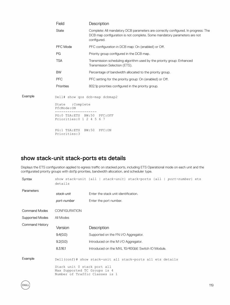
Field Description
State Complete: All mandatory DCB parameters are correctly configured. In progress: The DCB map configuration is not complete. Some mandatory parameters are not configured.
PFC Mode PFC configuration in DCB map: On (enabled) or Off.
PG Priority group configured in the DCB map.
TSA Transmission scheduling algorithm used by the priority group: Enhanced Transmission Selection (ETS).
BW Percentage of bandwidth allocated to the priority group.
PFC PFC setting for the priority group: On (enabled) or Off.
Priorities 802.1p priorities configured in the priority group.
Example Dell# show qos dcb-map dcbmap2
State :CompletePfcMode:ON--------------------PG:0 TSA:ETS BW:50 PFC:OFFPriorities:0 1 2 4 5 6 7
PG:1 TSA:ETS BW:50 PFC:ONPriorities:3
show stack-unit stack-ports ets detailsDisplays the ETS configuration applied to egress traffic on stacked ports, including ETS Operational mode on each unit and the configurated priority groups with dot1p priorities, bandwidth allocation, and scheduler type.
Syntax show stack-unit {all | stack-unit} stack-ports {all | port-number} ets details
Parametersstack-unit Enter the stack unit identification.
port-number Enter the port number.
Command Modes CONFIGURATION
Supported Modes All Modes
Command HistoryVersion Description
9.4(0.0) Supported on the FN I/O Aggregator.
9.2(0.0) Introduced on the M I/O Aggregator.
8.3.16.1 Introduced on the MXL 10/40GbE Switch IO Module.
Example Dell(conf)# show stack-unit all stack-ports all ets details
Stack unit 0 stack port allMax Supported TC Groups is 4Number of Traffic Classes is 1
119
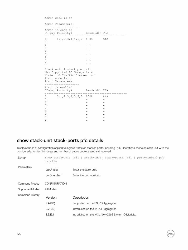
Admin mode is on
Admin Parameters:--------------------Admin is enabledTC-grp Priority# Bandwidth TSA------------------------------------------------0 0,1,2,3,4,5,6,7 100% ETS1 - -2 - -3 - -4 - -5 - -6 - -7 - -8 - -
Stack unit 1 stack port allMax Supported TC Groups is 4Number of Traffic Classes is 1Admin mode is onAdmin Parameters:--------------------Admin is enabledTC-grp Priority# Bandwidth TSA------------------------------------------------0 0,1,2,3,4,5,6,7 100% ETS1 - -2 - -3 - -4 - -5 - -6 - -7 - -8 - -
show stack-unit stack-ports pfc detailsDisplays the PFC configuration applied to ingress traffic on stacked ports, including PFC Operational mode on each unit with the configured priorities, link delay, and number of pause packets sent and received.
Syntax show stack-unit {all | stack-unit} stack-ports {all | port-number} pfc details
Parametersstack-unit Enter the stack unit.
port-number Enter the port number.
Command Modes CONFIGURATION
Supported Modes All Modes
Command HistoryVersion Description
9.4(0.0) Supported on the FN I/O Aggregator.
9.2(0.0) Introduced on the M I/O Aggregator.
8.3.16.1 Introduced on the MXL 10/40GbE Switch IO Module.
120

Example Dell(conf)# show stack-unit all stack-ports all pfc details
stack unit 0 stack-port all Admin mode is On Admin is enabled, Priority list is 4-5 Local is enabled, Priority list is 4-5 Link Delay 45556 pause quantum 0 Pause Tx pkts, 0 Pause Rx pkts
stack unit 1 stack-port all Admin mode is On Admin is enabled, Priority list is 4-5 Local is enabled, Priority list is 4-5 Link Delay 45556 pause quantum 0 Pause Tx pkts, 0 Pause Rx pkts
121

8Dynamic Host Configuration ProtocolDynamic host configuration protocol (DHCP) is an application layer protocol that dynamically assigns IP addresses and other configuration parameters to network end-stations (hosts) based on configuration policies determined by network administrators.
An Aggregator can operate as a DHCP client. As a DHCP client, the Aggregator requests an IP address from a DHCP server.
The following types of DHCP commands are described in this chapter:
• DHCP Client Commands
• Other Commands supported by DHCP Client
DHCP Client Commands
• clear ip dhcp client statistics
• ip address dhcp
• release dhcp interface
• renew dhcp interface
• show ip dhcp client statistics
• show ip dhcp lease
Other Commands supported by DHCP Client
• debug ip dhcp client events
• debug ip dhcp client packets
clear ip dhcp client statisticsDisplays DHCP client statistics, including the number of DHCP messages sent and received on an interface.
Syntax clear ip dhcp client statistics interface type slot/portParameters
interface type slot/port
Clear DHCP client statistics on the specified interface.
• For the management interface on the stack-unit, enter the keyword managementethernet followed by slot/port information. The slot and port
range is 0.
• For a VLAN, enter the keyword vlan followed by a number from 1 to 4094.
Command Modes EXEC Privilege
Supported Modes All Modes
Default None
122

Command HistoryVersion Description
9.4(0.0) Supported on the FN I/O Aggregator.
8.3.17.0 Supported on the M I/O Aggregator.
debug ip dhcp client eventsEnable the display of log messages for the following events on DHCP client interfaces:
• IP address acquisition
• IP address release
• Renewal of IP address and lease time
• Release of an IP address
Syntax debug ip dhcp client events [interface type slot/port]Parameters
interface type slot/port
Display log messages for DHCP packets sent and received on the specified interface.
• For the management interface on the stack-unit, enter the keyword managementethernet followed by slot/port information. The slot and port range is 0
• For a VLAN, enter the keyword vlan followed by a number from 1 to 4094.
Command Modes EXEC Privilege
Supported Modes All Modes
Default None
Command HistoryVersion Description
9.4(0.0) Supported on the FN I/O Aggregator.
8.3.17.0 Supported on the M I/O Aggregator.
debug ip dhcp client packetsEnable the display of log messages for all DHCP packets sent and received on DHCP client interfaces.
Syntax debug ip dhcp client packets [interface type slot/port]Parameters
interface type slot/port
Display log messages for DHCP packets sent and received on the specified interface.
• For the management interface on the stack-unit, enter the keyword managementethernet followed by slot/port information. The slot and port range is 0
123

• For a VLAN, enter the keyword vlan followed by a number from 1 to 4094.
Command Modes EXEC Privilege
Supported Modes All Modes
Default None
Command HistoryVersion Description
9.4(0.0) Supported on the FN I/O Aggregator.
8.3.17.0 Supported on the M I/O Aggregator.
ip address dhcpAcquire an IP address dynamically on an interface from the DHCP server.
Syntax ip address dhcp [relay | vendor-class-identifier] To disable DHCP Client on an interface, use the no ip address dhcp command.
Command Modes INTERFACE
Supported Modes All Modes
Default Enabled
Command HistoryVersion Description
9.4(0.0) Supported on the FN I/O Aggregator.
8.3.17.0 Supported on the M I/O Aggregator.
Usage Information In the I/O Aggregator, the DHCP client is enabled only on the default VLAN and management interface 0/0. Use the ip address command to assign a static IP address that overwrites the dynamically assigned IP
address.
release dhcp interfaceRelease the dynamically-acquired IP address on an Ethernet interface while retaining the DHCP client configuration on the interface.
Syntax release dhcp interface type slot/portParameters
interface type slot/port • For the management interface on the stack-unit, enter the keyword
management ethernet followed by slot/port information. The slot and port range is 0.
• For a VLAN, enter the keyword vlan followed by a number from 1 to 4094.
Command Modes EXEC Privilege
124

Supported Modes All Modes
Default None
Command HistoryVersion Description
9.4(0.0) Supported on the FN I/O Aggregator.
9.2(0.0) Supported on the M I/O Aggregator.
Usage Information When you enter the release dhcp command, although the IP address that was dynamically-acquired
from a DHCP server is released from an interface, the ability to acquire a new DHCP server-assigned address remains in the running configuration for the interface. To acquire a new IP address, enter either the renew dhcp command at the EXEC privilege level or the ip address dhcp command at the interface
configuration level.
renew dhcp interfaceRe-acquire a dynamic IP address on an Ethernet interface enabled as a DHCP client.
Syntax renew dhcp interface type slot/port}Parameters
interface type slot/port
Enter any of the following keywords and slot/port or number to clear counters from a specified interface:
• For the management interface on the stack-unit, enter the keyword managementethernet followed by slot/port information. The slot and port
range is 0.
• For a VLAN, enter the keyword vlan followed by a number from 1 to 4094.
Command Modes EXEC Privilege
Supported Modes All Modes
Default None.
Command HistoryVersion Description
9.4(0.0) Supported on the FN I/O Aggregator.
8.3.17.0 Supported on the M I/O Aggregator.
Usage information The renew dhcp command is used to renew the lease of IP address obtained through dhcp.
To display the currently configure dynamic IP address and lease time, enter the show ip dhcp lease command.
125

show ip dhcp client statisticsDisplays DHCP client statistics, including the number of DHCP messages sent and received on an interface.
Syntax show ip dhcp client statistics interface type slot/portParameters
interface type slot/port
Display DHCP client statistics on the specified interface.
• For the management interface on the stack-unit, enter the keyword managementethernet followed by slot/port information. The slot and port range is 0.
• For a VLAN, enter the keyword vlan followed by a number from 1 to 4094.
Command Modes EXEC Privilege
Supported Modes All Modes
Default None.
Command HistoryVersion Description
9.4(0.0) Supported on the FN I/O Aggregator.
8.3.17.0 Supported on the M I/O Aggregator.
show ip dhcp leaseDisplays lease information about the dynamic IP address currently assigned to a DHCP client-enabled interface.
Syntax show ip dhcp lease[interface type slot/port]Parameters
interface type slot/port
Display DHCP client statistics on the specified interface.
• For the management interface on the stack-unit, enter the keyword managementethernet followed by slot/port information. The slot and port range is 0.
• For a VLAN, enter the keyword vlan followed by a number from 1 to 4094.
Command Modes EXEC Privilege
Supported Modes All Modes
Default Display DHCP lease information on all DHCP client-enabled interfaces on the switch.
Command HistoryVersion Description
9.4(0.0) Supported on the FN I/O Aggregator.
8.3.17.0 Supported on the M I/O Aggregator.
126

9FIP SnoopingIn a converged Ethernet network, an Aggregator can operate as an intermediate Ethernet bridge to snoop on Fibre Channel over Ethernet Initialization Protocol (FIP) packets during the login process on Fibre Channel over Ethernet (FCoE) forwarders (FCFs). Acting as a transit FIP snooping bridge, the switch uses dynamically-created ACLs to permit only authorized FCoE traffic to be transmitted between an FCoE end-device and an FCF.
This chapter describes the FIP snooping commands.
clear fip-snooping database interface vlanClear FIP snooping information on a VLAN for a specified FCoE MAC address, ENode MAC address, or FCF MAC address, and remove the corresponding ACLs FIP snooping generates.
Syntax clear fip-snooping database interface vlan vlan-id {fcoe-mac-address | enode-mac-address | fcf-mac-address}
Parametersfcoe-mac-address Enter the FCoE MAC address to be cleared of FIP snooping information.
enode-mac-address
Enter the ENode MAC address to be cleared of FIP snooping information.
fcf-mac-address Enter the FCF MAC address to be cleared of FIP snooping information.
Command Modes EXEC Privilege
Supported Modes Programmable-Mux (PMUX)
Command HistoryVersion Description
9.4(0.0) Supported on the FN I/O Aggregator.
9.2(0.0) Introduced on the M I/O Aggregator.
8.3.16.1 Introduced on the MXL 10/40GbE Switch IO Module.
clear fip-snooping statistics
Clear the statistics on the FIP packets snooped on all VLANs, a specified VLAN, or a specified port interface.
Syntax clear fip-snooping statistics [interface vlanVlan-id| interfaceport-type port/slot|interface port-channel port-channel-number]
Parametersvlan-id Enter the VLAN ID of the FIP packet statistics to be cleared.
port type port/slot Enter the port-type and slot number of the FIP packet statistics to be cleared.
127

port-channel-number
Enter the port channel number of the FIP packet statistics to be cleared.
Command Modes EXEC Privilege
Supported Modes All Modes
Command HistoryVersion Description
9.4(0.0) Supported on the FN I/O Aggregator.
9.2(0.0) Introduced on the M I/O Aggregator.
8.3.16.1 Introduced on the MXL 10/40GbE Switch IO Module.
feature fip-snooping
Enable FCoE transit and FIP snooping on a switch.
Syntax feature fip-snoopingTo disable the FCoE transit feature, use the no feature fip-snooping command.
Defaults Disabled
Command Modes CONFIGURATION
Supported Modes Programmable-Mux (PMUX)
Command HistoryVersion Description
9.4(0.0) Supported on the FN I/O Aggregator.
9.2(0.0) Introduced on the M I/O Aggregator.
8.3.16.1 Introduced on the MXL 10/40GbE Switch IO Module.
fip-snooping enable
Enable FIP snooping on all VLANs or on a specified VLAN.
Syntax fip-snooping enableTo disable the FIP snooping feature on all or a specified VLAN, use the no fip-snooping enable command.
Defaults FIP snooping is disabled on all VLANs.
Command Modes• CONFIGURATION
• VLAN INTERFACE
Supported Modes Programmable-Mux (PMUX)
Command HistoryVersion Description
9.4(0.0) Supported on the FN I/O Aggregator.
9.2(0.0) Introduced on the M I/O Aggregator.
128

Version Description
8.3.16.1 Introduced on the MXL 10/40GbE Switch IO Module.
Usage Information The maximum number of FCFs supported per FIP snooping-enabled VLAN is four. The maximum number of FIP snooping sessions supported per ENode server is 16.
fip-snooping fc-map
Configure the FC-MAP value FIP snooping uses on all VLANs.
Syntax fip-snooping fc-map fc-map-valueTo return the configured FM-MAP value to the default value, use the no fip-snooping fc-map command.
Parametersfc-map-value Enter the FC-MAP value FIP snooping uses. The range is from 0EFC00 to 0EFCFF.
Defaults 0x0EFC00
Command Modes• CONFIGURATION
• VLAN INTERFACE
Supported Modes Programmable-Mux (PMUX)
Command HistoryVersion Description
9.4(0.0) Supported on the FN I/O Aggregator.
9.2(0.0) Introduced on the M I/O Aggregator.
8.3.16.1 Introduced on the MXL 10/40GbE Switch IO Module.
fip-snooping port-mode fcf
Configure the port for bridge-to-FCF links.
Syntax fip-snooping port-mode fcfTo disable the bridge-to-FCF link on a port, use the no fip-snooping port-mode fcf command.
Command Modes INTERFACE
Supported Modes Programmable-Mux (PMUX)
Command HistoryVersion Description
9.4(0.0) Supported on the FN I/O Aggregator.
9.2(0.0) Introduced on the M I/O Aggregator.
8.3.16.1 Introduced on the MXL 10/40GbE Switch IO Module.
Usage Information The maximum number of FCFs supported per FIP snooping-enabled VLAN is four.
129

show fip-snooping statisticsDisplays statistics on the FIP packets snooped on all interfaces, including VLANs, physical ports, and port channels..
Syntax show fip-snooping statistics [interface vlan vlan-id | interface port-type port/slot | interface port-channel port-channel-number]
Parametersvlan-id Enter the VLAN ID of the FIP packet statistics to be displayed.
port-type port/slot Enter the port-type and slot number of the FIP packet statistics to be displayed.
port-channel-number
Enter the port channel number of the FIP packet statistics to be displayed.
Command Modes• EXEC
• EXEC Privilege
Supported Modes All Modes
Command HistoryVersion Description
9.4(0.0) Supported on the FN I/O Aggregator.
8.3.17.0 Supported on the M I/O Aggregator.
Usage Information The following table describes the show fip-snooping statistics command.
Field Description
Number of Vlan Requests
Number of FIP-snooped VLAN request frames received on the interface.
Number of VLAN Notifications
Number of FIP-snooped VLAN notification frames received on the interface
Number of Multicast Discovery Solicits
Number of FIP-snooped multicast discovery solicit frames received on the interface.
Number of Unicast Discovery
Number of FIP-snooped unicast discovery solicit frames received on the interface.
Number of FLOGI Number of FIP-snooped FLOGI request frames received on the interface.
Number of FDISC Number of FIP-snooped FDISC request frames received on the interface
Number of FLOGO Number of FIP-snooped FLOGO frames received on the interface
Number of ENode Keep Alives
Number of FIP-snooped ENode keep-alive frames received on the interface
Number of VN Port Keep Alives
Number of FIP-snooped VN port keep-alive frames received on the interface
130

Field Description
Number of Multicast Discovery Advertisements
Number of FIP-snooped multicast discovery advertisements received on the interface
Number of Unicast Discovery Advertisements
Number of FIP-snooped unicast discovery advertisements received on the interface
Number of FLOGI Accepts
Number of FIP FLOGI accept frames received on the interface
Number of FLOGI Rejects
Number of FIP FLOGI reject frames received on the interface
Number of FDISC Accepts
Number of FIP FDISC accept frames received on the interface
Number of FDISC Rejects
Number of FIP FDISC reject frames received on the interface
Number of FLOGO Accepts
Number of FIP FLOGO accept frames received on the interface
Number of FLOGO Rejects
Number of FIP FLOGO reject frames received on the interface
Number of CVLs Number of FIP clear virtual link frames received on the interface
Number of FCF Discovery
Number of FCF discovery timeouts that occurred on the interface
Number of VN Port Session
Number of VN port session timeouts that occurred on the interface
Number of Session failures due to Hardware Config
Number of session failures due to hardware configuration that occurred on the interface
Example Dell# show fip-snooping statistics interface vlan 100Number of Vlan Requests :0Number of Vlan Notifications :0Number of Multicast Discovery Solicits :2Number of Unicast Discovery Solicits :0Number of FLOGI :2Number of FDISC :16Number of FLOGO :0Number of Enode Keep Alive :9021Number of VN Port Keep Alive :3349Number of Multicast Discovery Advertisement :4437Number of Unicast Discovery Advertisement :2Number of FLOGI Accepts :2Number of FLOGI Rejects :0Number of FDISC Accepts :16Number of FDISC Rejects :0Number of FLOGO Accepts :0Number of FLOGO Rejects :0Number of CVL :0Number of FCF Discovery Timeouts :0Number of VN Port Session Timeouts :0Number of Session failures due to Hardware Config :0Dell(conf)#
131

Dell# show fip-snooping statistics int tengigabitethernet 0/11Number of Vlan Requests :1Number of Vlan Notifications :0Number of Multicast Discovery Solicits :1Number of Unicast Discovery Solicits :0Number of FLOGI :1Number of FDISC :16Number of FLOGO :0Number of Enode Keep Alive :4416Number of VN Port Keep Alive :3136Number of Multicast Discovery Advertisement :0Number of Unicast Discovery Advertisement :0Number of FLOGI Accepts :0Number of FLOGI Rejects :0Number of FDISC Accepts :0Number of FDISC Rejects :0Number of FLOGO Accepts :0Number of FLOGO Rejects :0Number of CVL :0Number of FCF Discovery Timeouts :0Number of VN Port Session Timeouts :0Number of Session failures due to Hardware Config :0
Example (port channel)
Dell# show fip-snooping statistics interface port-channel 22Number of Vlan Requests :0Number of Vlan Notifications :2Number of Multicast Discovery Solicits :0Number of Unicast Discovery Solicits :0Number of FLOGI :0Number of FDISC :0Number of FLOGO :0Number of Enode Keep Alive :0Number of VN Port Keep Alive :0Number of Multicast Discovery Advertisement :4451Number of Unicast Discovery Advertisement :2Number of FLOGI Accepts :2Number of FLOGI Rejects :0Number of FDISC Accepts :16Number of FDISC Rejects :0Number of FLOGO Accepts :0Number of FLOGO Rejects :0Number of CVL :0Number of FCF Discovery Timeouts :0Number of VN Port Session Timeouts :0Number of Session failures due to Hardware Config :0
debug fip-snoopingEnable the debug FIP protocol specific messages.
Syntax debug fip-snooping [all | acl | error | ifm | info | ipc | rx { packet-type { all | discovery | virtual-link-instantiation | virtual-link-maintenance | vlan-discovery } { port-channel | tengigabitethernet } } | tx ]
Parametersall Enable all the debug options.
acl Enable for ACL specific debugs.
error Enable for Error specific debugs.
ifm Enable for IFM specific debugs.
132

info Enable for Information specific debugs.
ipc Enable for IPC specific debugs.
rx Enable for packet receive specific debugs.
packet-type Specify the packet type. Options are:
• all
• discovery
• virtual-link-instantiation
• virtual-link-maintenance
• vlan-discovery
all Enable for all the packet types.
discovery Enable for FIP discovery solicits (enodes) and adverts (fcf).
virtual-link-instantiation
Enable for flogi, fdisc and flogo packets.
virtual-link-maintenance
Enable for clear virtual link and keepalive packets.
vlan-discovery Enable for FIP VLAN requests and notifications.
port-channel Port-channel interface.
tengigabitethernet TenGigabit Ethernet interface.
tx Enable for packet transmit specific debugs.
Command Modes EXEC Privilege
Supported Modes All Modes
Command HistoryVersion Description
9.4(0.0) Supported on the FN I/O Aggregator.
show fip-snooping configDisplays the FIP snooping status and configured FC-MAP values.
Syntax show fip-snooping configCommand Modes
• EXEC
• EXEC Privilege
Supported Modes All Modes
Command HistoryVersion Description
9.4(0.0) Supported on the FN I/O Aggregator.
8.3.17.0 Supported on the M I/O Aggregator.
133

Example Dell#show fip-snooping configFIP Snooping Feature enabled Status: EnabledFIP Snooping Global enabled Status: EnabledGlobal FC-MAP Value: 0X0EFC00Maximum Sessions Per Enode Mac: 32Dell#
show fip-snooping enodeDisplays information on the ENodes in FIP-snooped sessions, including the ENode interface and MAC address, FCF MAC address, VLAN ID, and FC-ID.
Syntax show fip-snooping enode [enode-mac-address]Parameters
enode-mac-address
Enter the MAC address of the ENodes to be displayed.
Command Modes• EXEC
• EXEC Privilege
Supported Modes All Modes
Command HistoryVersion Description
9.4(0.0) Supported on the FN I/O Aggregator.
8.3.17.0 Supported on the M I/O Aggregator.
Usage Information The following table describes the show fip-snooping enode command.
Field Description
ENode MAC MAC address of the ENode
ENode Interface Slot/ port number of the interface connected to the ENode.
FCF MAC MAC address of the FCF
VLAN VLAN ID number used by the session
FC-ID Fibre Channel session ID assigned by the FCF.
Example Dell# show fip-snooping enodeEnode MAC Enode Interface FCF MAC VLAN FC-ID--------- --------------- ------- ---- ------ d4:ae:52:1b:e3:cd Te 0/11 54:7f:ee:37:34:40 100 62:00:11
134

show fip-snooping fcfDisplays information on the FCFs in FIP-snooped sessions, including the FCF interface and MAC address, FCF interface, VLAN ID, FC-MAP value, FKA advertisement period, and number of ENodes connected.
Syntax show fip-snooping fcf[fcf-mac-address]Parameters
fcf-mac-address Enter the MAC address of the FCF to be displayed.
Command Modes• EXEC
• EXEC Privilege
Supported Modes All Modes
Command HistoryVersion Description
9.4(0.0) Supported on the FN I/O Aggregator.
8.3.17.0 Supported on the M I/O Aggregator.
Usage Information The following table describes the show fip-snooping fcf command.
Field Description
FCF MAC MAC address of the FCF
FCF Interface Slot/ port number of the interface to which the FCF is connected.
VLAN VLAN ID number used by the session
FC-MAP FC-MAP value advertised by the FCF.
FKA_ADV_PERIOD Period of time (in milliseconds) during which FIP keep-alive advertisements are transmitted.
No of ENodes Number of ENodes connected to the FCF
Example Dell# show fip-snooping fcfFCF MAC FCF Interface VLAN FC-MAP FKA_ADV_PERIOD No. of Enodes------- ------------- ---- ------ -------------- -------------54:7f:ee:37:34:40 Po 128 100 0e:fc:00 4000 1
show fip-snooping sessionsDisplays information on FIP-snooped sessions on all VLANs or a specified VLAN, including the ENode interface and MAC address, the FCF interface and MAC address, VLAN ID, FCoE MAC address and FCoE session ID number (FC-ID), worldwide node name (WWNN) and the worldwide port name (WWPN).
Syntax show fip-snooping sessions[interface vlan vlan-id]Parameters
vlan-id Enter the vlan-id of the specified VLAN to be displayed.
135

Command Modes• EXEC
• EXEC Privilege
Supported Modes All Modes
Command HistoryVersion Description
9.4(0.0) Supported on the FN I/O Aggregator.
8.3.17.0 Supported on the M I/O Aggregator.
Usage Information The following table describes the show fip-snooping sessions command.
Field Description
ENode MAC MAC address of the ENode.
ENode Interface Slot/ port number of the interface connected to the ENode.
FCF MAC MAC address of the FCF.
FC Interface Slot/ port number of the interface to which the FCF is connected.
VLAN VLAN ID number used by the session.
FCoE MAC MAC address of the FCoE session assigned by the FCF.
FC-ID Fibre Channel ID assigned by the FCF.
Port WWPN Worldwide port name of the CNA port.
Port WWNN Worldwide node name of the CNA port.
Example Dell#show fip-snooping sessionsEnode MAC Enode Intf FCF MAC FCF Intf VLAN FCoE MAC FC-ID00:0e:1e:0c:54:a6 Te 0/14 00:05:73:f2:4f:ae Po128 100 0e:fc:00:9a:00:27 9a:00:27 20:01:00:0e:1e:0c:54:a600:0e:1e:06:01:5e Te 0/16 00:05:73:f2:4f:af Po128 100 0e:fc:00:9a:01:18 9a:01:18 20:01:00:0e:1e:06:01:5Port WWNN20:00:00:0e:1e:0c:54:a620:00:00:0e:1e:0c:54:a6
show fip-snooping statisticsDisplays statistics on the FIP packets snooped on all interfaces, including VLANs, physical ports, and port channels..
Syntax show fip-snooping statistics [interface vlan vlan-id | interface port-type port/slot | interface port-channel port-channel-number]
Parametersvlan-id Enter the VLAN ID of the FIP packet statistics to be displayed.
port-type port/slot Enter the port-type and slot number of the FIP packet statistics to be displayed.
port-channel-number
Enter the port channel number of the FIP packet statistics to be displayed.
136

Command Modes• EXEC
• EXEC Privilege
Supported Modes All Modes
Command HistoryVersion Description
9.4(0.0) Supported on the FN I/O Aggregator.
8.3.17.0 Supported on the M I/O Aggregator.
Usage Information The following table describes the show fip-snooping statistics command.
Field Description
Number of Vlan Requests
Number of FIP-snooped VLAN request frames received on the interface.
Number of VLAN Notifications
Number of FIP-snooped VLAN notification frames received on the interface
Number of Multicast Discovery Solicits
Number of FIP-snooped multicast discovery solicit frames received on the interface.
Number of Unicast Discovery
Number of FIP-snooped unicast discovery solicit frames received on the interface.
Number of FLOGI Number of FIP-snooped FLOGI request frames received on the interface.
Number of FDISC Number of FIP-snooped FDISC request frames received on the interface
Number of FLOGO Number of FIP-snooped FLOGO frames received on the interface
Number of ENode Keep Alives
Number of FIP-snooped ENode keep-alive frames received on the interface
Number of VN Port Keep Alives
Number of FIP-snooped VN port keep-alive frames received on the interface
Number of Multicast Discovery Advertisements
Number of FIP-snooped multicast discovery advertisements received on the interface
Number of Unicast Discovery Advertisements
Number of FIP-snooped unicast discovery advertisements received on the interface
Number of FLOGI Accepts
Number of FIP FLOGI accept frames received on the interface
Number of FLOGI Rejects
Number of FIP FLOGI reject frames received on the interface
Number of FDISC Accepts
Number of FIP FDISC accept frames received on the interface
137

Field Description
Number of FDISC Rejects
Number of FIP FDISC reject frames received on the interface
Number of FLOGO Accepts
Number of FIP FLOGO accept frames received on the interface
Number of FLOGO Rejects
Number of FIP FLOGO reject frames received on the interface
Number of CVLs Number of FIP clear virtual link frames received on the interface
Number of FCF Discovery
Number of FCF discovery timeouts that occurred on the interface
Number of VN Port Session
Number of VN port session timeouts that occurred on the interface
Number of Session failures due to Hardware Config
Number of session failures due to hardware configuration that occurred on the interface
Example Dell# show fip-snooping statistics interface vlan 100Number of Vlan Requests :0Number of Vlan Notifications :0Number of Multicast Discovery Solicits :2Number of Unicast Discovery Solicits :0Number of FLOGI :2Number of FDISC :16Number of FLOGO :0Number of Enode Keep Alive :9021Number of VN Port Keep Alive :3349Number of Multicast Discovery Advertisement :4437Number of Unicast Discovery Advertisement :2Number of FLOGI Accepts :2Number of FLOGI Rejects :0Number of FDISC Accepts :16Number of FDISC Rejects :0Number of FLOGO Accepts :0Number of FLOGO Rejects :0Number of CVL :0Number of FCF Discovery Timeouts :0Number of VN Port Session Timeouts :0Number of Session failures due to Hardware Config :0Dell(conf)#
Dell# show fip-snooping statistics int tengigabitethernet 0/11Number of Vlan Requests :1Number of Vlan Notifications :0Number of Multicast Discovery Solicits :1Number of Unicast Discovery Solicits :0Number of FLOGI :1Number of FDISC :16Number of FLOGO :0Number of Enode Keep Alive :4416Number of VN Port Keep Alive :3136Number of Multicast Discovery Advertisement :0Number of Unicast Discovery Advertisement :0Number of FLOGI Accepts :0Number of FLOGI Rejects :0Number of FDISC Accepts :0Number of FDISC Rejects :0Number of FLOGO Accepts :0Number of FLOGO Rejects :0
138

Number of CVL :0Number of FCF Discovery Timeouts :0Number of VN Port Session Timeouts :0Number of Session failures due to Hardware Config :0
Example (port channel)
Dell# show fip-snooping statistics interface port-channel 22Number of Vlan Requests :0Number of Vlan Notifications :2Number of Multicast Discovery Solicits :0Number of Unicast Discovery Solicits :0Number of FLOGI :0Number of FDISC :0Number of FLOGO :0Number of Enode Keep Alive :0Number of VN Port Keep Alive :0Number of Multicast Discovery Advertisement :4451Number of Unicast Discovery Advertisement :2Number of FLOGI Accepts :2Number of FLOGI Rejects :0Number of FDISC Accepts :16Number of FDISC Rejects :0Number of FLOGO Accepts :0Number of FLOGO Rejects :0Number of CVL :0Number of FCF Discovery Timeouts :0Number of VN Port Session Timeouts :0Number of Session failures due to Hardware Config :0
show fip-snooping systemDisplays information on the status of FIP snooping on the switch (enabled or disabled), including the number of FCoE VLANs, FCFs, ENodes, and currently active sessions.
Syntax show fip-snooping systemCommand Modes
• EXEC
• EXEC Privilege
Supported Modes All Modes
Command HistoryVersion Description
9.4(0.0) Supported on the FN I/O Aggregator.
8.3.17.0 Supported on the M I/O Aggregator.
Example Dell# show fip-snooping systemGlobal Mode : EnabledFCOE VLAN List (Operational) : 1, 100FCFs : 1Enodes : 2Sessions : 17
139

show fip-snooping vlanDisplay information on the FIP snooping operational VLANs.
Syntax show fip-snooping vlanCommand Modes
• EXEC
• EXEC Privilege
Supported Modes All Modes
Command HistoryVersion Description
9.4(0.0) Supported on the FN I/O Aggregator.
8.3.17.0 Introduced on the M I/O Aggregator.
Example Dell# show fip-snooping vlan* = Default VLAN
VLAN FC-MAP FCFs Enodes Sessions---- ------ ---- ------ --------*1 - - - -1002 0X0EFC00 1 1 1
140

10Internet Group Management Protocol (IGMP)The Dell Networking OS supports IGMP snooping version 2 and 3 on all Dell Networking systems.
IGMP CommandsThe Dell Networking OS supports the following IGMP commands:
• clear ip igmp groups
• debug ip igmp
• ip igmp group-join-limit
• ip igmp querier-timeout
• ip igmp query-interval
• ip igmp query-max-resp-time
• ip igmp snooping enable
• ip igmp snooping fast-leave
• ip igmp snooping flood
• ip igmp snooping last-member-query-interval
• ip igmp snooping mrouter
• ip igmp snooping querier
• ip igmp version
• show ip igmp groups
• show ip igmp interface
• show ip igmp snooping mrouter
Important Points to Remember
• Dell Networking OS supports version 1, version 2, and version 3 hosts.
• Dell Networking OS IGMP snooping implementation is based on IP multicast address (not based on Layer 2 multicast mac-address) and the IGMP snooping entries are in Layer 3 flow table not in Layer 2 forwarding information base (FIB).
• Dell Networking OS IGMP snooping implementation is based on draft-ietf-magma-snoop-10.
• IGMP snooping is enabled by default on the switch.
• A maximum of 2k groups and 4k virtual local area networks (VLAN) are supported.
• IGMP snooping is not supported on default VLAN interface.
• Flooding of unregistered multicast traffic is enabled by default.
• Queries are not accepted from the server side ports and are only accepted from the uplink LAG.
• Reports and Leaves are flooded by default to the uplink LAG irrespective of whether it is an mrouter port or not.
141

IGMP Snooping CommandsDell Networking OS supports IGMP Snooping version 2 and 3 on all Dell Networking systems.
Important Points to Remember for IGMP Snooping
• Dell Networking OS supports version 1, version 2, and version 3 hosts.
• Dell Networking OS IGMP snooping implementation is based on IP multicast address (not based on Layer 2 multicast mac address) and the IGMP snooping entries are in Layer 3 flow table not in Layer 2 forwarding information base (FIB).
• Dell Networking OS IGMP snooping implementation is based on draft-ietf-magma-snoop-10.
• Dell Networking OS supports IGMP snooping on JUMBO-enabled cards.
• IGMP snooping is not enabled by default on the switch.
• A maximum of 1800 groups and 600 VLAN are supported.
• IGMP snooping is not supported on a default VLAN interface.
• IGMP snooping is not supported over VLAN-Stack-enabled VLAN interfaces (you must disable IGMP snooping on a VLAN interface before configuring VLAN-Stack-related commands).
clear ip igmp groupsClear entries from the group cache table.
Syntax clear ip igmp groups [group-address | interface]Parameters
group-address (OPTIONAL) Enter the IP multicast group address in dotted decimal format.
interface (OPTIONAL) Enter the interface type and slot/port information: For a VLAN interface enter the keyword vlan followed by a number from 1 to 4094.
Command Modes EXEC Privilege
Supported Modes All Modes
Command HistoryVersion Description
9.4(0.0) Supported on the FN I/O Aggregator.
8.3.17.0 Supported on the M I/O Aggregator.
debug ip igmpEnable debugging of IGMP packets.
Syntax debug ip igmp [group address | interface]To disable IGMP debugging, enter the no ip igmp command. To disable all debugging, enter the
undebug all command.
Defaults Disabled
Parametersgroup-address (OPTIONAL) Enter the IP multicast group address in dotted decimal format.
142

interface (OPTIONAL) Enter the interface type and slot/port information:
For a VLAN interface enter the keyword vlan followed by a number from 1 to 4094.
Command Modes EXEC Privilege
Supported Modes All Modes
Command HistoryVersion Description
9.4(0.0) Supported on the FN I/O Aggregator.
8.3.17.0 Supported on the M I/O Aggregator.
ip igmp group-join-limitTo limit the number of IGMP groups that can be joined in a second, use this feature.
Syntax ip igmp group-join-limit numberParameters
number Enter the number of IGMP groups permitted to join in a second. The range is from 1 to 10000.
Defaults none
Command Modes CONFIGURATION (conf-if-interface-slot/port)
Supported Modes Programmable-Mux (PMUX)
Command HistoryVersion Description
9.4(0.0) Supported on the FN I/O Aggregator.
9.2(0.0) Introduced on the M I/O Aggregator.
ip igmp querier-timeoutChange the interval that must pass before a multicast router decides that there is no longer another multicast router that should be the querier.
Syntax ip igmp querier-timeout secondsTo return to the default value, use the no ip igmp querier-timeout command.
Parametersseconds Enter the number of seconds the router must wait to become the new querier. The
range is from 60 to 300. The default is 125 seconds.
Defaults 125 seconds
Command Modes INTERFACE
Supported Modes Programmable-Mux (PMUX)
143

Command HistoryVersion Description
9.4(0.0) Supported on the FN I/O Aggregator.
9.2(0.0) Introduced on the M I/O Aggregator.
ip igmp query-intervalChange the transmission frequency of IGMP general queries the Querier sends.
Syntax ip igmp query-interval secondsTo return to the default values, use the no ip igmp query-interval command.
Parametersseconds Enter the number of seconds between queries sent out. The range is from 1 to
18000. The default is 60 seconds.
Defaults 60 seconds
Command Modes INTERFACE
Supported Modes Programmable-Mux (PMUX)
Command HistoryVersion Description
9.4(0.0) Supported on the FN I/O Aggregator.
9.2(0.0) Introduced on the M I/O Aggregator.
ip igmp query-max-resp-timeSet the maximum query response time advertised in general queries.
Syntax ip igmp query-max-resp-time secondsTo return to the default values, use the no ip igmp query-max-resp-time command.
Parametersseconds Enter the number of seconds for the maximum response time. The range is from 1
to 25. The default is 10 seconds.
Defaults 10 seconds
Command Modes INTERFACE
Supported Modes Programmable-Mux (PMUX)
Command HistoryVersion Description
9.4(0.0) Supported on the FN I/O Aggregator.
9.2(0.0) Introduced on the M I/O Aggregator.
144

ip igmp snooping enableEnable IGMP snooping on all or a single VLAN. This command is the master on/off switch to enable IGMP snooping.
Syntax ip igmp snooping enableTo disable IGMP snooping, use the no ip igmp snooping enable command.
Defaults Disabled.
Command Modes• CONFIGURATION
• INTERFACE VLAN
Supported Modes Programmable-Mux (PMUX)
Command HistoryVersion Description
9.4(0.0) Supported on the FN I/O Aggregator.
9.2(0.0) Introduced on the M I/O Aggregator.
Usage Information To enable IGMP snooping, enter this command. When you enable this command from CONFIGURATION mode, IGMP snooping enables on all VLAN interfaces (except the default VLAN).
NOTE: Execute the no shutdown command on the VLAN interface for IGMP Snooping to
function.
ip igmp snooping fast-leaveEnable IGMP snooping fast-leave for this VLAN.
Syntax ip igmp snooping fast-leaveTo disable IGMP snooping fast leave, use the no igmp snooping fast-leave command.
Defaults Not configured.
Command Modes INTERFACE VLAN — (conf-if-vl-n)
Supported Modes Programmable-Mux (PMUX)
Command HistoryVersion Description
9.4(0.0) Supported on the FN I/O Aggregator.
9.2(0.0) Introduced on the M I/O Aggregator.
Usage Information Queriers normally send some queries when a leave message is received prior to deleting a group from the membership database. There may be situations when you require a fast deletion of a group. When you enable IGMP fast leave processing, the switch removes an interface from the multicast group as soon as it detects an IGMP version 2 leave message on the interface.
145

ip igmp snooping floodThis command controls the flooding behavior of unregistered multicast data packets. When flooding is disabled, unregistered multicast data traffic is forwarded to only multicast router ports in a VLAN. If there is no multicast router port in a VLAN, unregistered multicast data traffic is dropped.
Syntax ip igmp snooping floodTo disable the flooding, use the no ip igmp snooping flood command.
Parameters Enabled
Command Modes CONFIGURATION
Supported Modes All Modes
Command HistoryVersion Description
9.4(0.0) Supported on the FN I/O Aggregator.
8.3.17.0 Supported on the M I/O Aggregator.
ip igmp snooping last-member-query-intervalThe last member query interval is the maximum response time inserted into Group-Specific queries sent in response to Group-Leave messages.
Syntax ip igmp snooping last-member-query-interval millisecondsTo return to the default value, use the no ip igmp snooping last-member-query-interval command.
Parametersmilliseconds Enter the interval in milliseconds. The range is from 100 to 65535. The default is
1000 milliseconds.
Defaults 1000 milliseconds
Command Modes INTERFACE VLAN
Supported Modes Programmable-Mux (PMUX)
Command HistoryVersion Description
9.4(0.0) Supported on the FN I/O Aggregator.
9.2(0.0) Introduced on the M I/O Aggregator.
Usage Information This last-member-query-interval is also the interval between successive Group-Specific Query messages. To change the last-member-query interval, use this command.
146

ip igmp snooping mrouterStatically configure a VLAN member port as a multicast router interface.
Syntax ip igmp snooping mrouter interface interfaceTo delete a specific multicast router interface, use the no igmp snooping mrouter interface interface command.
Parametersinterface interface Enter the following keywords and slot/port or number information:
• For a 10-Gigabit Ethernet interface, enter the keyword TenGigabitEthernet then the slot/port information.
• For a Port Channel interface, enter the keywords port-channel then a number. The range is from 1 to 128.
Defaults Not configured.
Command Modes INTERFACE VLAN — (conf-if-vl-n)
Supported Modes Programmable-Mux (PMUX)
Command HistoryVersion Description
9.4(0.0) Supported on the FN I/O Aggregator.
Usage Information Dell Networking OS provides the capability of statically configuring the interface to which a multicast router is attached. To configure a static connection to the multicast router, enter the ip igmp snooping mrouter interface command in the VLAN context. The interface to the router must be a part of the
VLAN where you are entering the command.
ip igmp snooping querierEnable IGMP querier processing for the VLAN interface.
Syntax ip igmp snooping querierTo disable IGMP querier processing for the VLAN interface, use the no ip igmp snooping querier command.
Defaults Not configured.
Command Modes INTERFACE VLAN — (conf-if-vl-n)
Supported Modes Programmable-Mux (PMUX)
Command HistoryVersion Description
9.4(0.0) Supported on the FN I/O Aggregator.
9.2(0.0) Introduced on the M I/O Aggregator.
Usage Information This command enables the IGMP switch to send General Queries periodically. This behavior is useful when there is no multicast router present in the VLAN because the multicast traffic is not routed. Assign an IP address to the VLAN interface for the switch to act as a querier for this VLAN.
147

ip igmp versionManually set the version of the router to IGMPv2 or IGMPv3.
Syntax ip igmp version {2 | 3}Parameters
2 Enter the number 2 to set the IGMP version number to IGMPv2.
3 Enter the number 3 to set the IGMP version number to IGMPv3.
Defaults 2 (that is, IGMPv2)
Command Modes INTERFACE
Supported Modes Programmable-Mux (PMUX)
Command HistoryVersion Description
9.4(0.0) Supported on the FN I/O Aggregator.
9.2(0.0) Introduced on the M I/O Aggregator.
show ip igmp groupsView the IGMP groups.
Syntax show ip igmp groups [group-address [detail] | detail | interface [group-address [detail]]]
Parametersgroup-address (OPTIONAL) Enter the group address in dotted decimal format to view information
on that group only.
interface (OPTIONAL) Enter the interface type and slot/port information:
For a VLAN interface enter the keyword vlan followed by a number from 1 to 4094.
detail (OPTIONAL) Enter the keyword detail to display the IGMPv3 source information.
Command Modes• EXEC
• EXEC Privilege
Supported Modes All Modes
Command HistoryVersion Description
9.4(0.0) Supported on the FN I/O Aggregator.
8.3.17.0 Supported on the M I/O Aggregator.
Example Dell#show ip igmp groupsTotal Number of Groups: 5IGMP Connected Group MembershipGroup Address Interface Mode UptimeExpires Last Reporter225.0.0.0 Vlan 100 IGMPv2 00:00:05
148

00:02:04 3.0.0.51Member Ports: Po 2225.0.0.2 Vlan 100 IGMPv2 00:00:0500:02:04 3.0.0.51Member Ports: Po 2225.0.0.3 Vlan 100 IGMPv2 00:00:0500:02:04 3.0.0.51Member Ports: Po 2225.0.0.4 Vlan 100 IGMPv2 00:00:0500:02:04 3.0.0.51Member Ports: Po 2
Field Description
Group Address Lists the multicast address for the IGMP group.
Interface Lists the interface type, slot and port number.
Mode Displays the IGMP version used.
Uptime Displays the amount of time the group has been operational.
Expires Displays the amount of time until the entry expires.
Last Reporter Displays the IP address of the last host to be a member of the IGMP group.
Member Ports Indicates the member ports of the port channel. If the port channel is VLT, an asterisk (*) after the port channel number indicates the port channel is locally down and that a remote VLT port is up.
show ip igmp interfaceView information on the interfaces participating in IGMP.
Syntax show ip igmp interface [interface]Parameters
interface (OPTIONAL) Enter any of the following keywords and slot/port or number to clear counters from a specified interface:
• For a Port Channel interface, enter the keyword port-channel followed by a number. Range: 1-128
• For a 10-Gigabit Ethernet interface, enter the keyword TenGigabitEthernet followed by the slot/port information.
• For a VLAN, enter the keyword vlan followed by a number from 1 to 4094.
Command Modes• EXEC
• EXEC Privilege
Supported Modes All Modes
149

Command HistoryVersion Description
9.4(0.0) Supported on the FN I/O Aggregator.
8.3.17.0 Supported on the M I/O Aggregator.
Example Dell#show ip igmp interfaceVlan 2 is up, line protocol is downInbound IGMP access group is not setInterface IGMP group join rate limit is not setIGMP snooping is enabled on interfaceIGMP Snooping query interval is 60 secondsIGMP Snooping querier timeout is 125 secondsIGMP Snooping last member query response interval is 1000 msIGMP snooping fast-leave is disabled on this interfaceIGMP snooping querier is disabled on this interfaceVlan 3 is up, line protocol is downInbound IGMP access group is not setInterface IGMP group join rate limit is not setIGMP snooping is enabled on interfaceIGMP Snooping query interval is 60 secondsIGMP Snooping querier timeout is 125 secondsIGMP Snooping last member query response interval is 1000 msIGMP snooping fast-leave is disabled on this interfaceIGMP snooping querier is disabled on this interface--More--
show ip igmp snooping mrouterDisplays multicast router interfaces.
Syntax show ip igmp snooping mrouter [vlan number]Parameters
vlan number Enter the keyword vlan followed by the vlan number. Range: 1 to 4094
Command Modes• EXEC
• EXEC Privilege
Supported Modes All Modes
Command HistoryVersion Description
9.4(0.0) Supported on the FN I/O Aggregator.
8.3.17.0 Supported on the M I/O Aggregator.
Example Dell#show ip igmp snooping mrouter vlan 2Interface Router PortsVlan 2 Po 128Dell#
Related Commands show ip igmp groups — Use this IGMP command to view groups.
150

11InterfacesThis chapter defines the interface commands on the Aggregator switch.
Port Interface CommandsThe following commands are for physical, loopback, and null interfaces:
• clear counters
• clear mac-address-table dynamic
• interface range
• interface vlan
• keepalive
• monitor interface
• name
• show config (INTERFACE mode)
• show config (from INTERFACE RANGE mode)
• show config (from INTERFACE VLAN mode)
• show interfaces configured
• show interfaces description
• show interfaces stack-unit
• show interfaces port-channel
• show interfaces status
• show interfaces switchport
• show vlan
• shutdown
• speed (for 1000/10000 interfaces)
Port Channel CommandsA Link Aggregation Group (LAG) is a group of links that appear to a MAC client as if they were a single link according to IEEE 802.3ad. In Dell Networking OS, a LAG is referred to as a Port Channel.
• For the Aggregator, the maximum port channel ID is 128 and the maximum members per port channel is 4.
Because each port can be assigned to only one Port Channel, and each Port Channel must have at least one port, some of those nominally available Port Channels might have no function because they could have no members if there are not enough ports installed.
NOTE: For information about Dell Networking OS link aggregation control protocol (LACP) for dynamic LAGs, refer to the Link Aggregation Control Protocol (LACP) chapter. For more information about configuring and using Port Channels, refer to the Dell PowerEdge FN I/O Aggregator Configuration Guide
151

Time Domain Reflectometer (TDR) CommandsTDR is useful for troubleshooting an interface that is not establishing a link; either it is flapping or not coming up at all. TDR detects open or short conditions of copper cables on 100/1000/10G Base-T modules.
• tdr-cable-test
• show tdr
Important Points to Remember
• The interface and port must be enabled (configured—see the interface command) before running TDR. An error message is generated if you have not enabled the interface.
• The interface on the far-end device must be shut down before running TDR.
• Because TDR is an intrusive test on an interface that is not establishing a link, do not run TDR on an interface that is passing traffic.
• When testing between two devices, do not run the test on both ends of the cable.
Virtual LAN (VLAN) CommandsThe following commands configure and monitor virtual local area networks (VLANs). VLANs are a virtual interface and use many of the same commands as physical interfaces.
You can configure an IP address only on the default VLAN. FTP, TFTP, ACLs, and SNMP are not supported on a VLAN.
Occasionally, while sending broadcast traffic over multiple VLANs, state of a VLAN interface may continually switch between Master and Backup.
• auto vlan
• default vlan-id
• name
• show config (from INTERFACE VLAN mode)
• show vlan
• vlan tagged
• vlan untagged
auto vlanChange the port to auto or admin vlan mode (enable or disable all auto VLANs).
Syntax auto vlanTo remove membership from 4K VLAN, use the no auto vlan command.
Defaults none
Parametersdescription Enter a text string description to identify the VLAN (80 characters maximum).
Command Modes INTERFACE
Supported Modes Standalone Mode
Usasge Information The auto vlan command adds the port as untagged to default vlan and tagged to all other 4094 VLAN.
152

Command HistoryVersion Description
9.4(0.0) Supported on the FN I/O Aggregator.
8.3.17.0 Supported on the M I/O Aggregator.
channel-memberAdd an interface to the Port Channel, while in INTERFACE PORTCHANNEL mode.
Syntax channel-member interfaceTo delete an interface from a Port Channel, use the no channel-member interface command.
Parametersinterface (OPTIONAL) Enter the following keywords and slot/port or number information:
• For a 10-Gigabit Ethernet interface, enter the keyword TenGigabitEthernet then the slot/port information.
Defaults Not configured.
Command Modes INTERFACE PORTCHANNEL
Supported Modes Programmable-Mux (PMUX)
Command HistoryVersion Description
9.4(0.0) Supported on the FN I/O Aggregator.
Usage Information Use the interface port-channel command to access this command.
You cannot add an interface to a Port Channel if the interface contains an IP address in its configuration.
Link MTU and IP MTU considerations for Port Channels are:
• All members must have the same link MTU value and the same IP MTU value.
• The Port Channel link MTU and IP MTU must be less than or equal to the link MTU and IP MTU values configured on the channel members. For example, if the members have a link MTU of 2100 and an IP MTU 2000, the Port Channel’s MTU values cannot be higher than 2100 for link MTU or 2000 bytes for IP MTU.
When an interface is removed from a Port Channel with the no channel-member command, the
interface reverts to its configuration prior to joining the Port Channel.
An interface can belong to only one Port Channel.
You can add up to 16 interfaces to a Port Channel on the MXL switch. The interfaces can be located on different line cards but must be the same physical type and speed (for example, all 10-Gigabit Ethernet interfaces). However, you can combine 100/1000 interfaces and GE interfaces in the same Port Channel.
If the Port Channel contains a mix of interfaces with 100 Mb/s speed and 1000 Mb/s speed, the software disables those interfaces whose speed does not match the speed of the first interface configured and enabled in the Port Channel. If that first interface goes down, the Port Channel does not change its designated speed; disable and re-enable the Port Channel or change the order of the channel members
153

configuration to change the designated speed. If the Port Channel contains a mix of interfaces with 100 Mb/s speed and 1000 Mb/s speed, the software disables those interfaces whose speed does not match the speed of the first interface configured and enabled in the Port Channel. If that first interface goes down, the Port Channel does not change its designated speed; disable and re-enable the Port Channel or change the order of the channel members configuration to change the designated speed. For more information about Port Channels, refer to the Dell Networking OS Configuration Guide.
Related Commands interface port-channel — creates a Port Channel interface.
clear countersClear the counters used in the show interfaces commands for VLANs, and physical interfaces, or selected ones.
Syntax clear counters interfaceDefaults Without a specific interface specified, the command clears all interface counters.
Parametersinterface (OPTIONAL) Enter any of the following keywords and slot/port or number to clear
counters from a specified interface:
• For the management interface on the stack-unit, enter the keyword managementethernet followed by slot/port information. The slot and port range is 0.
• For a 10-Gigabit Ethernet interface, enter the keyword TenGigabitEthernet followed by the slot/port information.
• For a Port Channel interface, enter the keyword port-channel followed by a number. Range: 1-128
Command Modes EXEC Privilege
Supported Modes All Modes
Command HistoryVersion Description
9.4(0.0) Supported on the FN I/O Aggregator.
8.3.17.0 Supported on the M I/O Aggregator.
Example Dell#clear countersClear counters on all interfaces [confirm]
clear mac-address-table dynamicClear the MAC address table of all MAC addresses learned dynamically.
Syntax clear mac-address-table dynamic {interface tengigabitethernet slot/port-id}Parameters
interface Enter the keyword interface range and one of the interfaces — slot/port,
port-channel or VLAN number. Select the range of interfaces for bulk
154

configuration. You can enter up to six comma separated ranges-spaces are not required between the commas. Comma-separated ranges can include VLANs, port-channels and physical interfaces.
Slot/Port information must contain a space before and after the dash. For example, interface range tengigabitethernet 0/1 - 5 is valid; interface range tengigabitethernet 0/1-5 is not valid.
• For a 10-Gigabit Ethernet interface, enter the keyword TenGigabitEthernet followed by the slot/port information.
Command Modes EXEC Privilege
Supported Modes All Modes
Command HistoryVersion Description
9.4(0.0) Supported on the FN I/O Aggregator.
8.3.17.0 Supported on the M I/O Aggregator.
default vlan-idSet the default VLAN ID.
Syntax default vlan-id <vlan-id>To reset the default VLAN ID, use the no default vlan-id command.
Defaults none
Command Modes CONFIGURATION
Supported Modes All Modes
Command HistoryVersion Description
9.4(0.0) Supported on the FN I/O Aggregator.
8.3.17.0 Supported on the M I/O Aggregator.
Related commands show vlan — Displays VLAN configuration.
descriptionAssign a descriptive text string to the interface.
Syntax description desc_textTo delete a description, enter no description command.
Parametersdesc_text Enter a text string up to 240 characters long.
155

Defaults No description is defined.
Command Modes INTERFACE
Supported Modes All Modes
Command HistoryVersion Description
9.4(0.0) Supported on the FN I/O Aggregator.
8.3.17.0 Supported on the M I/O Aggregator.
Usage Information• Spaces between characters are not preserved after entering this command unless you enclose the entire
description in quotation marks (“desc_text”).
• Entering a text string after the default vlan-id command overwrites any previous text string
configured as the description.
• The show tdr and default vlan-id commands are the only commands that you can configure
on an interface that is a member of a port-channel.
• Use the show interfaces description command to display descriptions configured for each interface.
Related commands show interfaces description — Displays the description field of interfaces.
feature fcEnables the Fibre channel communication via the NPG functionality.
Syntax feature fcCommand Modes CONFIGURATION
Default Enabled
Supported Modes Programmable-Mux (PMUX)
Command HistoryVersion Description
9.6(0.0) Supported on the FN 2210S Aggregator and M I/O Aggregator.
flowcontrolControl how the system responds to and generates 802.3x pause frames on 10G and 40Gig stack units.
Syntax flowcontrol rx {off | on} tx {off | on} thresholdParameters
rx on Enter the keywords rx on to process the received flow control frames on this port. This is the
default value for the receive side.
rx off Enter the keywords rx off to ignore the received flow control frames on this port.
156

tx on Enter the keywords tx on to send control frames from this port to the connected device when a
higher rate of traffic is received. This is the default value on the send side.
tx off Enter the keywords tx off so that flow control frames are not sent from this port to the
connected device when a higher rate of traffic is received.
Defaults• rx off• tx off
Command Modes INTERFACE
Supported Modes Programmable-Mux (PMUX)
Command HistoryVersion Description
9.4(0.0) Supported on the FN I/O Aggregator.
9.2(0.0) Introduced on the M I/O Aggregator.
8.3.16.1 Introduced on the MXL 10/40GbE Switch IO Module.
Usage Information The globally assigned 48-bit Multicast address 01-80-C2-00-00-01 is used to send and receive pause frames. To allow full-duplex flow control, stations implementing the pause operation instruct the MAC to enable the reception of frames with a destination address equal to this multicast address.
The pause:
• Starts when either the packet pointer or the buffer threshold is met (whichever is met first). When the discard threshold is met, packets are dropped.
• Ends when both the packet pointer and the buffer threshold fall below 50% of the threshold settings.
The discard threshold defines when the interface starts dropping the packet on the interface. This may be necessary when a connected device does not honor the flow control frame sent by the switch. The discard threshold should be larger than the buffer threshold so that the buffer holds at least hold at least three packets.
Important Points to Remember
• Do not enable tx pause when buffer carving is enabled. For information and assistance, consult Dell Networking TAC.
• Asymmetric flow control (rx on tx off, or rx off tx on) setting for the interface port less than 100 Mb/s speed is not permitted. The following error is returned:
Can’t configure Asymmetric flowcontrol when speed <1G, config ignored• The only configuration applicable to half duplex ports is rx off tx off. The following error is returned:
Cannot configure Asymmetric flowcontrol when speed <1G, config ignored>• You cannot configure half duplex when the flow control configuration is on (default is rx on tx on). The following
error is returned: Cannot configure half duplex when flowcontrol is on, config ignored
NOTE: The flow control must be off (rx off tx off) before configuring the half duplex.
Example (partial) Dell(conf-if-tengig-0/1)#show config!interface TenGigabitEthernet 0/1no ip addressswitchportno negotiation autoflowcontrol rx off tx on
157

no shutdown...
Example (Values) This Example shows how the Dell Networking OS negotiates the flow control values between two Dell Networking chassis connected back-to-back using 1G copper ports.
Configured LocRxConf LocTxConf RemoteRxConf RemoteTxConf off off off off off on on off on on
off on off off off on on off on on
on off off off off on on off on on
on on off off off on on off on on
LocNegRx LocNegTx RemNegRx RemNegTxoff off off offoff off off offoff off off offoff off off off
off off off offoff off off offoff on on offoff off off off
off off off offon off off onon on on onon on on on
off off off offoff off off offon on on onon on on on
Related Commands show running-config — displays the flow configuration parameters (non-default values only).
show interfaces — displays the interface configuration.
interfaceConfigure a physical interface on the switch.
Syntax interface interface Parameters
interface Enter one of the following keywords and slot/port or number information:
158

• For a 10-Gigabit Ethernet interface, enter the keyword TenGigabitEthernet then the slot/port information.
Defaults Not configured.
Command Modes CONFIGURATION
Supported Modes All Modes
Command HistoryVersion Description
9.4(0.0) Supported on the FN I/O Aggregator.
8.3.17.0 Supported on the M I/O Aggregator.
Usage Information You cannot delete a physical interface.
By default, physical interfaces are disabled (shutdown) and are in Layer 3 mode. To place an interface in
mode, ensure that the interface’s configuration does not contain an IP address and enter the Port Channel Commands command.
The tunnel interface operates as an ECMP (equal cost multi path) only when the next hop to the tunnel destination is over a physical interface. If you select any other interface as the next hop to the tunnel destination, the tunnel interface does not operate as an ECMP.
Example Dell(conf)#interface tengig 0/1Dell(conf-if-te-0/1)#exit#
Related Commands interface port-channel — configures a port channel.
interface vlan — configures a VLAN.
show interfaces — displays the interface configuration.
interface ManagementEthernetConfigure the Management port on the system.
Syntax interface ManagementEthernet slot/portParameters
slot/port Enter the keyword ManagementEthernet, then the slot number (0) and port
number zero (0).
Defaults Not configured.
Command Modes CONFIGURATION
Supported Modes All Modes
Command HistoryVersion Description
9.4.(0.0) Supported on the FN I/O Aggregator and M I/O Aggregator.
159

Usage Information You cannot delete a Management port.
The Management port is enabled by default (no shutdown). To assign an IP address to the Management
port, use the ip address command.
Example Dell(conf)#interface managementethernet 0/0Dell(conf-if-ma-0/0)#
interface port-channelCreate a Port Channel interface, which is a link aggregation group (LAG) containing physical interfaces on the Aggregator.
Syntax interface port-channel channel-numberTo delete a Port Channel, use the no interface port-channel channel-number command.
Parameterschannel-number For a Port Channel interface, enter the keywords port-channel then a number.
The range is from 1 to 128.
Defaults Not configured.
Command Modes CONFIGURATION
Supported Modes Programmable-Mux (PMUX)
Command HistoryVersion Description
9.4(0.0) Supported on the FN I/O Aggregator.
9.2(0.0) Introduced on the M I/O Aggregator.
8.3.16.1 Introduced on the MXL 10/40GbE Switch IO Module.
Usage Information Port Channel interfaces are logical interfaces and can be either in Layer 2 mode (by using the switchport command) or Layer 3 mode (by configuring an IP address). You can add a Port Channel in Layer 2 mode to a VLAN.
A Port Channel can contain both 100/1000 interfaces and GE interfaces. Based on the first interface configured in the Port Channel and enabled, the Dell Networking OS determines if the Port Channel uses 100 Mb/s or 1000 Mb/s as the common speed. For more information, refer to channel-member.
If the line card is in a Jumbo mode chassis, you can also configure the mtu and ip mtu commands. The
Link MTU and IP MTU values configured on the channel members must be greater than the Link MTU and IP MTU values configured on the Port Channel interface.
NOTE: In a Jumbo-enabled system, you must configure all members of a Port Channel with the same link MTU values and the same IP MTU values.
Example Dell(conf)#int port-channel 2Dell(conf-if-po-2)#
Related Commands channel-member — adds a physical interface to the LAG.
160

interface — configures a physical interface.
interface vlan — configures a VLAN.
interface rangeThis command permits configuration of a range of interfaces to which subsequent commands are applied (bulk configuration). Using the interface range command, you can enter identical commands for a range of interface.
Syntax interface range interface, interface,...To delete a description, enter no description command.
Parametersinterface, interface,...
Enter the keyword interface range and one of the interfaces — slot/port, port-channel or VLAN number. Select the range of interfaces for bulk configuration. You can enter up to six comma separated ranges—spaces are not required between the commas. Comma-separated ranges can include VLANs, port-channels and physical interfaces.
Slot/Port information must contain a space before and after the dash. For example, interface range tengigabitethernet 0/1 - 5 is valid;
interface range tengigabitethernet 0/1-5 is not valid.
• For a 10-Gigabit Ethernet interface, enter the keyword TenGigabitEthernet followed by the slot/port information.
• For a VLAN, enter the keyword vlan followed by a number from 1 to 4094.
Defaults none
Command Modes CONFIGURATION
Supported Modes All Modes
Command HistoryVersion Description
9.4(0.0) Supported on the FN I/O Aggregator.
Usage Information When creating an interface range, interfaces appear in the order they are entered; they are not sorted. The command verifies that interfaces are present (physical) or configured (logical). Important things to remember:
• Bulk configuration is created if at least one interface is valid.
• Non-existing interfaces are excluded from the bulk configuration with a warning message.
• The interface range prompt includes interface types with slot/port information for valid interfaces. The prompt allows for a maximum of 32 characters. If the bulk configuration exceeds 32 characters, it is represented by an ellipsis ( ... ).
• When the interface range prompt has multiple port ranges, the smaller port range is excluded from the prompt.
• If overlapping port ranges are specified, the port range is extended to the smallest start port and the biggest end port.
161

Example-Bulk Configuration Warning Message
Dell(conf)#interface range tengig 0/1 - 2 , tengig 0/4 , tengig 0/7, fa 0/0% Warning: Non-existing ports (not configured) are ignored byinterface-range
Example-Interface Range prompt with Multiple Ports
Dell(conf)#interface range tengig 0/1 - 2 , tengig 0/3 - 5Dell(conf-if-range-te-0/1-5)#
Example-Interface Range prompt Overlapping Port Ranges
Dell(conf)#interface range tengig 0/1 - 2 , tengig 0/1 - 5Dell(conf-if-range-te-0/1-5)#Only VLAN and port-channel interfaces created using the interface vlan and vlan tagged commands can be used in the interface range command.
Use the show running-config command to display the VLAN and port-channel interfaces. VLAN or
port-channel interfaces that are not displayed in the show running-config command cannot be used
with the bulk configuration feature of the interface range command. You cannot create virtual
interfaces (VLAN, Port-channel) using the interface range command.
NOTE: If a range has VLAN, physical, and port-channel interfaces, only commands related to physical interfaces can be bulk configured. To configure commands specific to VLAN or port-channel, only those respective interfaces should be configured in a particular range.
Example-Single Range Bulk Configuration
Dell(conf)# interface range tengigabitethernet 0/1 - 5Dell(conf-if-range-te-0/1-5)# no shutdownDell(conf-if-range-te-0/1-5)#
Example-Multiple Range Bulk Configuration with VLAN and port channel
The following example shows how to use commas to add VLAN and port-channel interfaces to the range.
Dell(conf-if)# interface range tengigabitethernet 0/1 - 5, vlan 2 - 10, port-channel 1 - 25Dell(conf-if-range-te-0/1-5,vl-2-10,po-1-25)# no shutdownDell(conf-if-range-te-0/1-5,vl-2-10,po-1-25)#
Related commands show config (from INTERFACE RANGE mode) — Shows the bulk configuration interfaces.
show interfaces status — Displays a summary of interface information.
interface vlanConfigure a VLAN. Configure the default VLAN to enable Static or DCHP IP configuration. You can configure up to 4094 VLANs.
Syntax interface vlan vlan-idTo delete a VLAN, use the no interface vlan vlan-id command.
Parametersvlan-id Enter 1 for the default VLAN. Enter a number as the VLAN identifier. The range is
from 1 to 4096.
Defaults Not configured, except for the default VLAN, which is configured as VLAN 1.
Command Modes CONFIGURATION
Supported Modes All Modes
162

Command HistoryVersion Description
9.4(0.0) Supported on the FN I/O Aggregator.
8.3.17.0 Supported on the M I/O Aggregator.
Usage Information For more information about VLANs and the commands to configure them, refer to Virtual LAN (VLAN) Commands.
FTP, TFTP, and SNMP operations are not supported on a VLAN. MAC/IP ACLs are not supported.
Examples Dell(conf)#int vlan 1Dell(conf-if-vl-1)#Dell(conf)#int vlan 3Dell(conf-if-vl-3)#
Related commands show vlan — Displays the current VLAN configuration on the switch.
vlan tagged — Adds a Layer 2 interface to a VLAN as a tagged interface.
vlan untagged — Adds a Layer 2 interface to a VLAN as an untagged interface.
intf-type cr4 autonegSet the interface type as CR4 with auto-negotiation enabled.
Syntax intf-type cr4 autonegIf you configure intf-type cr4 autoneg, use the no intf-type cr4 autoneg command to set
the interface type as cr4 with autonegotiation disabled.
Defaults Not configured
Command Modes CONFIGURATION
Supported Modes All Modes
Command HistoryVersion Description
9.4(0.0) Supported on the FN I/O Aggregator.
8.3.17.0 Supported on the M I/O Aggregator.
Usage Information If you configure interface type as CR4 with auto-negotiation enabled, also configure CR4 with auto-
negotiation. Many DAC cable link issues are resolved by setting the interface type as CR4.
Related Commands interface — configures a physical interface.
interface port-channel — configures a port channel group.
163

keepaliveSend keepalive packets periodically to keep an interface alive when it is not transmitting data.
Syntax keepalive [seconds]To stop sending keepalive packets, use the no keepalive command.
Parametersseconds (OPTIONAL) For interfaces with PPP encapsulation enabled, enter the number of
seconds between keepalive packets. The range is from 0 to 23767. The default is 10 seconds.
Defaults Enabled.
Command Modes INTERFACE
Supported Modes All Modes
Command HistoryVersion Description
9.4(0.0) Supported on the FN I/O Aggregator.
9.2(0.0) Supported on the M I/O Aggregator.
8.3.16.1 Introduced on the MXL 10/40GbE Switch IO Module.
Usage Information When you configure keepalive, the system sends a self-addressed packet out of the configured interface
to verify that the far end of a WAN link is up. When you configure no keepalive, the system does not
send keepalive packets and so the local end of a WAN link remains up even if the remote end is down.
minimum-linksConfigure the minimum number of links in a LAG (Port Channel) that must be in “oper up” status for the LAG to be also in “oper up” status.
Syntax minimum-links numberParameters
number Enter the number of links in a LAG that must be in “oper up” status. The range is from 1 to 16. The default is 1.
Defaults 1
Command Modes INTERFACE
Supported Modes Programmable-Mux (PMUX)
Command HistoryVersion Description
9.4(0.0) Supported on the FN I/O Aggregator.
9.2(0.0) Introduced on the M I/O Aggregator.
8.3.16.1 Introduced on the MXL 10/40GbE Switch IO Module.
164

Usage Information If you use this command to configure the minimum number of links in a LAG that must be in “oper up” status, the LAG must have at least that number of “oper up” links before it can be declared as up. For example, if the required minimum is four, and only three are up, the LAG is considered down.
monitor interfaceMonitor counters on a single interface or all interfaces on a stack unit. The screen is refreshed every five seconds and the CLI prompt disappears.
Syntax monitor interface [interface]To disable monitoring and return to the CLI prompt, press the q key.
Parametersinterface (OPTIONAL) Enter the following keywords and slot/port or number information:
• For the management port, enter the keyword managementethernet followed by the slot (0) and the port (0).
• For a 10-Gigabit Ethernet interface, enter the keyword TenGigabitEthernet followed by the slot/port information.
• For a Port Channel interface, enter the keyword port-channel followed by a number. The range is from 1 to 128.
Command Modes• EXEC
• EXEC Privilege
Supported Modes All Modes
Command HistoryVersion Description
9.4(0.0) Supported on the FN I/O Aggregator.
Usage Information The delta column displays changes since the last screen refresh.
The following are the monitor command menu options.
Key Description
systest-3 Displays the host name assigned to the system.
monitor time Displays the amount of time since the monitor interface command was
entered.
time Displays the amount of time the chassis is up (since last reboot).
m Change the view from a single interface to all interfaces on the stack unit or visa-versa.
c Refresh the view.
b Change the counters displayed from Packets on the interface to Bytes.
r Change the [delta] column from change in the number of packets/bytes in the last interval to rate per second.
165

Key Description
l Change the view to the next interface on the stack unit, or if in the stack unit mode, the next stack unit in the chassis.
a Change the view to the previous interface on the stack unit, or if in line stack unit mode, the previous stack unit in the chassis.
T Increase the screen refresh rate.
t Decrease the screen refresh rate.
q Return to the CLI prompt.
Example (Single Interface)
systest-3 Monitor time: 00:00:06 Refresh Intvl.: 2s Time: 03:26:26
Interface: tengig 0/3, Enabled, Link is Up, Linespeed is 1000 Mbit
Traffic statistics: Current Rate Delta Input bytes: 9069828 43 Bps 86 Output bytes: 606915800 43 Bps 86 Input packets: 54001 0 pps 1 Output packets: 9401589 0 pps 1 64B packets: 67 0 pps 0 Over 64B packets: 49166 0 pps 1 Over 127B packets: 350 0 pps 0 Over 255B packets: 1351 0 pps 0 Over 511B packets: 286 0 pps 0Over 1023B packets: 2781 0 pps 0 Error statistics: Input underruns: 0 0 pps 0 Input giants: 0 0 pps 0 Input throttles: 0 0 pps 0 Input CRC: 0 0 pps 0 Input IP checksum: 0 0 pps 0 Input overrun: 0 0 pps 0 Output underruns: 0 0 pps 0 Output throttles: 0 0 pps 0
m - Change mode c - Clear screen l - Page up a - Page down T - Increase refresh interval t - Decrease refresh interval q - Quit
Example (All Interfaces)
systest-3 Monitor time: 00:01:31 Refresh Intvl.: 2s Time: 03:54:14
Interface Link In Packets [delta] Out Packets[delta] Gi 0/0 Down 0 0 0 0 Gi 0/1 Down 0 0 0 0 Gi 0/2 Up 61512 52 66160 42 Gi 0/3 Up 63086 20 9405888 24 Gi 0/4 Up 14697471418 2661481 133929896572661385 Gi 0/5 Up 3759 3 161959604 832816 Gi 0/6 Up 4070 3 8680346 5 Gi 0/7 Up 61934 34 138734357 72 Gi 0/8 Up 61427 1 59960 1 Gi 0/9 Up 62039 53 104239232 3 Gi 0/10 Up 17740044091 372 7373849244 79 Gi 0/11 Up 18182889225 44 7184747584 138 Gi 0/12 Up 18182682056 0 3682 1 Gi 0/13 Up 18182681434 43 6592378911 144 Gi 0/14 Up 61349 55 86281941 15 Gi 0/15 Up 59808 58 62060 27 Gi 0/16 Up 59889 1 61616 1 Gi 0/17 Up 0 0 14950126 81293
166
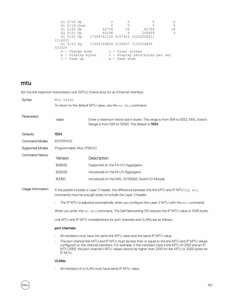
Gi 0/18 Up 0 0 0 0 Gi 0/19 Down 0 0 0 0 Gi 0/20 Up 62734 54 62766 18 Gi 0/21 Up 60198 9 200899 9 Gi 0/22 Up 17304741100 3157554 101025085111114221 Gi 0/23 Up 17304769659 3139507 7133354895523329 m - Change mode c - Clear screen b - Display bytes r - Display pkts/bytes per sec l - Page up a - Page down
mtuSet the link maximum transmission unit (MTU) (frame size) for an Ethernet interface.
Syntax mtu valueTo return to the default MTU value, use the no mtu command.
Parametersvalue Enter a maximum frame size in bytes. The range is from 594 to 9252. MXL Switch
Range is from 594 to 12000. The default is 1554.
Defaults 1554
Command Modes INTERFACE
Supported Modes Programmable-Mux (PMUX)
Command HistoryVersion Description
9.4(0.0) Supported on the FN I/O Aggregator.
9.2(0.0) Introduced on the M I/O Aggregator.
8.3.16.1 Introduced on the MXL 10/40GbE Switch IO Module.
Usage Information If the packet includes a Layer 2 header, the difference between the link MTU and IP MTU (ip mtu command) must be enough bytes to include the Layer 2 header.
• The IP MTU is adjusted automatically when you configure the Layer 2 MTU with the mtu command.
When you enter the no mtu command, The Dell Networking OS reduces the IP MTU value to 1536 bytes.
Link MTU and IP MTU considerations for port channels and VLANs are as follows.
port channels:
• All members must have the same link MTU value and the same IP MTU value.
• The port channel link MTU and IP MTU must be less than or equal to the link MTU and IP MTU values configured on the channel members. For example, if the members have a link MTU of 2100 and an IP MTU 2000, the port channel’s MTU values cannot be higher than 2100 for link MTU or 2000 bytes for IP MTU.
VLANs:
• All members of a VLAN must have same IP MTU value.
167

• Members can have different Link MTU values. Tagged members must have a link MTU 4 bytes higher than untagged members to account for the packet tag.
• The VLAN link MTU and IP MTU must be less than or equal to the link MTU and IP MTU values configured on the VLAN members. For example, the VLAN contains tagged members with Link MTU of 1522 and IP MTU of 1500 and untagged members with Link MTU of 1518 and IP MTU of 1500. The VLAN’s Link MTU cannot be higher than 1518 bytes and its IP MTU cannot be higher than 1500 bytes.
The following shows the difference between Link MTU and IP MTU.
Layer 2 Overhead
Link MTU and IP MTU Delta
Ethernet (untagged)
18 bytes
VLAN Tag 22 bytes
Untagged Packet with VLAN-Stack Header
22 bytes
Tagged Packet with VLAN-Stack Header
26 bytes
nameAssign a name to the Default VLAN.
Syntax namevlan-nameTo remove the name from the VLAN, use the no name command.
Parametersvlan-name Enter up to 32 characters as the name of the VLAN.
Defaults Not configured.
Command Modes INTERFACE VLAN
Supported Modes All Modes
Command HistoryVersion Description
9.4(0.0) Supported on the FN I/O Aggregator.
8.3.17.0 Supported on the M I/O Aggregator.
Usage Information This CLI applies only to the Default VLAN.
To display information about a named VLAN, enter the show vlan command with the name parameter or
the show interfaces description command.
Related commands default vlan-id —Assigns a descriptive text string to the interface.
interface vlan — Configures a VLAN.
168

show vlan — Displays the current VLAN configurations on the switch.
negotiation autoEnable auto-negotiation on an interface.
Syntax negotiation autoTo disable auto-negotiation, enter no negotiation auto command.
Defaults Enabled.
Command Modes INTERFACE
Supported Modes All Modes
Command HistoryVersion Description
9.4(0.0) Supported on the FN I/O Aggregator.
Usage Information The no negotiation auto command is only available if you first manually set the speed of a port to
10Mbits or 100Mbits.
Example (Configured)
Dell#show interfaces configuredTenGigabitEthernet 0/1 is up, line protocol is upHardware is DellEth, address is 00:1e:c9:de:04:9c Current address is 00:1e:c9:de:04:9cServer Port AdminState is N/APluggable media not presentInterface index is 33886978Internet address is not setMode of IPv4 Address Assignment : NONEDHCP Client-ID :001ec9de049cMTU 12000 bytes, IP MTU 11982 bytesLineSpeed 10000 MbitFlowcontrol rx on tx offARP type: ARPA, ARP Timeout 04:00:00Last clearing of "show interface" counters 03:56:48Queueing strategy: fifoInput Statistics:
User Information Both sides of the link must have auto-negotiation enabled or disabled for the link to come up.
The following details the possible speed and auto-negotiation combinations for a line between two 10/100/1000 Base-T Ethernet interfaces.
Port 0
• auto-negotiation enabled* speed 1000 or auto
• auto-negotiation enabled speed 100
• auto-negotiation disabled speed 100
• auto-negotiation disabled speed 100
• auto-negotiation enabled* speed 1000 or auto
Port 1
169

• auto-negotiation enabled* speed 1000 or auto
• auto-negotiation enabled speed 100
• auto-negotiation disabled speed 100
• auto-negotiation enabled speed 100
• auto-negotiation disabled speed 100
Link Status Between Port 1 and Port 2
• Up at 1000 Mb/s
• Up at 100 Mb/s
• Up at 100 Mb/s
• Down
• Down
* You cannot disable auto-negotiation when the speed is set to 1000 or auto.
Related Commands speed (for 1000/10000 interfaces) — sets the link speed to 10, 100, 1000 or auto-negotiate the speed.
show config (INTERFACE mode)Displays the interface configuration.
Syntax show configCommand Modes INTERFACE
Supported Modes All Modes
Command HistoryVersion Description
9.4(0.0) Supported on the FN I/O Aggregator.
8.3.17.0 Supported on the M I/O Aggregator.
Example Dell(conf-if)#show conf!interface TenGigabitEthernet 0/7 no ip address switchport no shutdownDell(conf-if)#
show config (from INTERFACE RANGE mode)Display the bulk configured interfaces (group).
Syntax show configCommand Modes CONFIGURATION INTERFACE (conf-if-range)
Supported Modes All Modes
170

Command HistoryVersion Description
9.4(0.0) Supported on the FN I/O Aggregator.
8.3.17.0 Supported on the M I/O Aggregator.
Example Dell(conf)#interface range tengigabitethernet 0/1 - 2Dell(conf-if-range-te-0/1-2)#show config!interface TenGigabitEthernet 0/1 no ip address switchport no shutdown!interface TenGigabitEthernet 0/2 no ip address switchport no shutdownDell(conf-if-range-te-0/1-2)#
show config (from INTERFACE VLAN mode)Displays the current configuration of the Default VLAN.
Syntax show configCommand Modes INTERFACE VLAN
Supported Modes All Modes
Command HistoryVersion Description
9.4(0.0) Supported on the FN I/O Aggregator.
8.3.17.0 Supported on the M I/O Aggregator.
Example Dell(conf-if-vl-1)#show config!interface Vlan 1description ano ip addressmtu 2500shutdownDell(conf-if-vl-1)#
show config (from PROTOCOL LLDP mode)Displays the LLDP configuration.
Syntax show configCommand Modes PROTOCOL LLDP
Supported Modes All Modes
171

Command HistoryVersion Description
9.4(0.0) Supported on the FN I/O Aggregator.
8.3.17.0 Supported on the M I/O Aggregator.
Example Dell(conf-lldp)#show conf!protocol lldpDell(conf-lldp)#
show interfacesDisplays information on a specific physical interface or virtual interface.
Syntax show interfaces interfaceParameters
interface Enter one of the following keywords and slot/port or number information:
• For the management interface on the stack-unit, enter the keyword managementethernet followed by slot/port information. The slot and port range is 0.
• For a 10-Gigabit Ethernet interface, enter the keyword TenGigabitEthernet then the slot/port information.
• For a VLAN interface, enter the keyword vlan followed by a number from 1 to 4094.
• For a Port Channel interface, enter the keyword port-channel followed by a number. The range is from 1 to 128.
Command Modes• EXEC
• EXEC Privilege
Supported Modes All Modes
Command HistoryVersion Description
9.4(0.0) Supported on the FN I/O Aggregator.
Usage Information Use this show interfaces command for details on a specific interface. Use the show interfaces stack-unit command for details on all interfaces on the designated stack unit.
On the I/O Aggregator, the show interface output displays incorrect rate information details over time for link monitoring when the rate-interval is configured for 5 seconds. Dell Networking recommends using higher rate-intervals such as 15 to 299 seconds to minimize the errors seen.
NOTE: In the CLI output, the power value will be rounded to a 3-digit value. For receive/transmit power that is less than 0.000, an snmp query will return the corresponding dbm value even though the CLI displays as 0.000.
NOTE: After the counters are cleared, the line-rate continues to increase until it reaches the maximum line rate. When the maximum line rate is reached, there will be no change in the line-rate.
172

User Information The following describes the show interfaces command shown in the 10G example below.
Line Description
TenGigabitEthernet 0/0...
Displays the interface’s type, slot/port, and administrative and line protocol status.
Hardware is... Displays the interface hardware information and its assigned MAC address.
Interface index... Displays the interface index number used by SNMP to identify the interface.
Internet address... States whether an IP address is assigned to the interface. If an IP address is assigned, that address is displayed.
MTU 1554... Displays link and IP MTU information. If the chassis is in Jumbo mode, this number can range from 576 to 12000.
LineSpeed Displays the interface’s line speed.
ARP type:... Displays the ARP type and the ARP timeout value for the interface.
Last clearing... Displays the time when the show interfaces counters where cleared.
Queuing strategy... States the packet queuing strategy. FIFO means first in first out.
Input Statistics: Displays all the input statistics including:
• Number of packets and bytes into the interface
• Number of packets with IP headers and VLAN tagged headers.
NOTE: The sum of the number of packets may not be as expected since a VLAN tagged IP packet counts as both a VLAN packet and an IP packet.
• Packet size and the number of those packets inbound to the interface
• Number of symbol errors, runts, giants, and throttles packets:
– symbol errors = number packets containing bad data. That is, the port MAC detected a physical coding error in the packet.
– runts = number of packets that are less than 64B
– giants = packets that are greater than the MTU size
– throttles = packets containing PAUSE frames
• Number of CRC, IP Checksum, overrun, and discarded packets:
– CRC = packets with CRC/FCS errors
– IP Checksum = packets with IP Checksum errors
– overrun = number of packets discarded due to FIFO overrun conditions
– discarded = the sum of runts, giants, CRC, IP Checksum, and overrun packets discarded without any processing
Output Statistics: Displays output statistics sent out of the interface including:
• Number of packets, bytes, and underruns out of the interface
– packets = total number of packets
– bytes = total number of bytes
– underruns = number of packets with FIFO underrun conditions
• Number of Multicast, Broadcast, and Unicast packets:
– Multicasts = number of MAC multicast packets
– Broadcasts = number of MAC broadcast packets
173

Line Description– Unicasts = number of MAC unicast packets
• Number of throttles and discards packets::
– throttles = packets containing PAUSE frames
– discarded = number of packets discarded without any processing
Rate information... Estimate of the input and output traffic rate over a designated interval (30 to 299 seconds). Traffic rate is displayed in bits, packets per second, and percent of line rate.
Time since... Elapsed time since the last interface status change (hh:mm:ss format).
Usage Information The interface counter “over 1023-byte pkts” does not increment for packets in the range 9216 > x <1023.
The Management port is enabled by default (no shutdown). If necessary, use the ip address command to assign an IP address to the Management port.
Example (ManagementEthernet)
Dell#show interface managementethernet ?0/0 Management Ethernet interface numberDell#show interface managementethernet 0/0ManagementEthernet 0/0 is up, line protocol is upHardware is DellForce10Eth, address is 00:1e:c9:f1:00:05Current address is 00:1e:c9:f1:00:05Pluggable media not presentInterface index is 235159752Internet address is 10.11.209.87/16Mode of IP Address Assignment : MANUALDHCP Client-ID: mgmt001ec9f10005Virtual-IP is not setVirtual-IP IPv6 address is not setMTU 1554 bytes, IP MTU 1500 bytesLineSpeed 100 Mbit, Mode full duplexARP type: ARPA, ARP Timeout 04:00:00Last clearing of "show interface" counters 5d4h57mQueueing strategy: fifoInput 3448753 packets, 950008323 bytes, 3442163 multicastReceived 0 errors, 0 discardedOutput 4627 packets, 814226 bytes, 0 multicastOutput 0 errors, 0 invalid protocol
Related Commands show interfaces configured — Displays any interface with a non-default configuration.
show interfaces port-channel — Displays information on all interfaces on a specific stack unit.
show interfaces switchport — Displays Layer 2 information about the interfaces.
show inventory — Displays the I/O Aggregator type, components (including media), Dell Networking OS version including hardware identification numbers and configured protocols.
show ip interface — Displays Layer 3 information about the interfaces.
show memory — Displays the stack unit(s) status.
show interfaces status — Displays all interfaces configured using the interface range command.
174

show interfaces configuredDisplays any interface with a non-default configuration.
Syntax show interfaces configuredCommand Modes
• EXEC
• EXEC Privilege
Supported Modes All Modes
Command HistoryVersion Description
9.4(0.0) Supported on the FN I/O Aggregator.
8.3.17.0 Supported on the M I/O Aggregator.
Example (ManagementEthernet)
Dell#show interfaces configuredTenGigabitEthernet 0/1 is up, line protocol is down(error-disabled[UFD])Hardware is DellForce10Eth, address is 00:01:e8:00:ab:01Current address is 00:01:e8:00:ab:01Server Port AdminState is DownPluggable media not presentInterface index is 67703553Internet address is not setMode of IP Address Assignment : NONEDHCP Client-ID :tenG2580001e800ab01MTU 12000 bytes, IP MTU 11982 bytesLineSpeed autoFlowcontrol rx off tx offARP type: ARPA, ARP Timeout 04:00:00Last clearing of "show interface" counters 05:15:07Queueing strategy: fifoInput Statistics:0 packets, 0 bytes0 64-byte pkts, 0 over 64-byte pkts, 0 over 127-byte pkts0 over 255-byte pkts, 0 over 511-byte pkts, 0 over 1023-byte pkts0 Multicasts, 0 Broadcasts0 runts, 0 giants, 0 throttles0 CRC, 0 overrun, 0 discardedOutput Statistics:0 packets, 0 bytes, 0 underruns0 64-byte pkts, 0 over 64-byte pkts, 0 over 127-byte pkts0 over 255-byte pkts, 0 over 511-byte pkts, 0 over 1023-byte pkts0 Multicasts, 0 Broadcasts, 0 Unicasts0 throttles, 0 discarded, 0 collisions, 0 wreddropsRate info (interval 299 seconds):Input 00.00 Mbits/sec, 0 packets/sec, 0.00% of line-rateOutput 00.00 Mbits/sec, 0 packets/sec, 0.00% of line-rateTime since last interface status change: 05:14:12TenGigabitEthernet 0/2 is up, line protocol is down(error-disabled[UFD])Dell#
show interfaces descriptionDisplay the descriptions configured on the interface.
Syntax show interfaces [interface] description
175
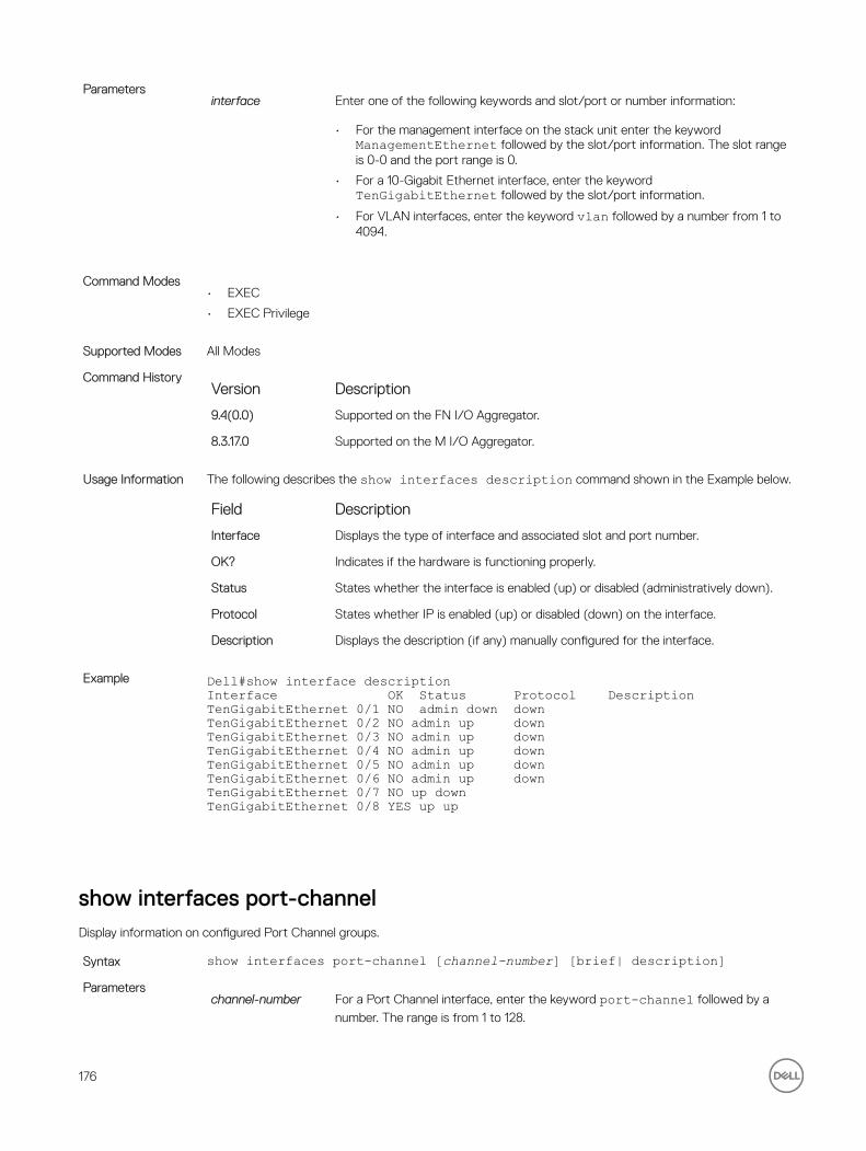
Parametersinterface Enter one of the following keywords and slot/port or number information:
• For the management interface on the stack unit enter the keyword ManagementEthernet followed by the slot/port information. The slot range is 0-0 and the port range is 0.
• For a 10-Gigabit Ethernet interface, enter the keyword TenGigabitEthernet followed by the slot/port information.
• For VLAN interfaces, enter the keyword vlan followed by a number from 1 to 4094.
Command Modes• EXEC
• EXEC Privilege
Supported Modes All Modes
Command HistoryVersion Description
9.4(0.0) Supported on the FN I/O Aggregator.
8.3.17.0 Supported on the M I/O Aggregator.
Usage Information The following describes the show interfaces description command shown in the Example below.
Field Description
Interface Displays the type of interface and associated slot and port number.
OK? Indicates if the hardware is functioning properly.
Status States whether the interface is enabled (up) or disabled (administratively down).
Protocol States whether IP is enabled (up) or disabled (down) on the interface.
Description Displays the description (if any) manually configured for the interface.
Example Dell#show interface descriptionInterface OK Status Protocol DescriptionTenGigabitEthernet 0/1 NO admin down downTenGigabitEthernet 0/2 NO admin up downTenGigabitEthernet 0/3 NO admin up downTenGigabitEthernet 0/4 NO admin up downTenGigabitEthernet 0/5 NO admin up downTenGigabitEthernet 0/6 NO admin up downTenGigabitEthernet 0/7 NO up downTenGigabitEthernet 0/8 YES up up
show interfaces port-channelDisplay information on configured Port Channel groups.
Syntax show interfaces port-channel [channel-number] [brief| description]Parameters
channel-number For a Port Channel interface, enter the keyword port-channel followed by a
number. The range is from 1 to 128.
176

brief (OPTIONAL) Enter the keyword brief to display only the port channel number,
the state of the port channel, and the number of interfaces in the port channel.
description (OPTIONAL) Enter the keyword description to display interface information with description.
Command Modes• EXEC
• EXEC Privilege
Supported Modes All Modes
Command HistoryVersion Description
9.7(0.0) Introduced on the M I/O Aggregator.
9.4(0.0) Supported on the FN I/O Aggregator.
Usage Information The following describes the show interfaces port-channel command shown in the following
example.
Field Description
Port-Channel 1... Displays the status of LAG. In the Example, the status of the LAG, LAG fate-sharing group (“Failover-group”) is listed.
Hardware is... Displays the interface’s hardware information and its assigned MAC address.
Port-channel is part...
Indicates whether the LAG is part of a LAG fate-sharing group (“Failover-group”).
Internet address... States whether an IP address is assigned to the interface. If an IP address is assigned, that address is displayed.
MTU 1554... Displays link and IP MTU.
LineSpeed Displays the interface’s line speed. For a port channel interface, it is the line speed of the interfaces in the port channel.
Members in this... Displays the interfaces belonging to this port channel.
ARP type:... Displays the ARP type and the ARP timeout value for the interface.
Last clearing... Displays the time when the show interfaces counters were cleared.
Queueing strategy. States the packet queuing strategy. FIFO means first in first out.
packets input... Displays the number of packets and bytes into the interface.
Input 0 IP packets... Displays the number of packets with IP headers, VLAN tagged headers, and MPLS headers. The number of packets may not add correctly because a VLAN tagged IP packet counts as both a VLAN packet and an IP packet.
0 64-byte... Displays the size of packets and the number of those packets entering that interface. This information is displayed over two lines.
Received 0... Displays the type and number of errors or other specific packets received. This information is displayed over three lines.
Output 0... Displays the type and number of packets sent out the interface. This information is displayed over three lines.
Rate information... Displays the traffic rate information into and out of the interface. Traffic rate is displayed in bits and packets per second.
177

Field Description
Time since... Displays the time since the last change in the configuration of this interface.
Example (EtherScale)
Dell#show interfaces port-channelPort-channel 1 is down, line protocol is downHardware address is 00:1e:c9:f1:00:05, Current address is 00:1e:c9:f1:00:05Interface index is 1107755009Minimum number of links to bring Port-channel up is 1Internet address is not setMode of IP Address Assignment : NONEDHCP Client-ID :lag1001ec9f10005MTU 12000 bytes, IP MTU 1500 bytesLineSpeed autoMembers in this channel:ARP type: ARPA, ARP Timeout 04:00:00Last clearing of "show interface" counters 03:28:00Queueing strategy: fifoInput Statistics:0 packets, 0 bytes0 64-byte pkts, 0 over 64-byte pkts, 0 over 127-byte pkts0 over 255-byte pkts, 0 over 511-byte pkts, 0 over 1023-byte pkts0 Multicasts, 0 Broadcasts0 runts, 0 giants, 0 throttles0 CRC, 0 overrun, 0 discardedOutput Statistics:0 packets, 0 bytes, 0 underruns0 64-byte pkts, 0 over 64-byte pkts, 0 over 127-byte pkts0 over 255-byte pkts, 0 over 511-byte pkts, 0 over 1023-byte pkts0 Multicasts, 0 Broadcasts, 0 Unicasts0 throttles, 0 discarded, 0 collisions
User Information The following describes the show interfaces port-channel brief command shown in the
following example.
Field Description
LAG Lists the port channel number.
Mode Lists the mode:
• L3 — for Layer 3
• L2 — for Layer 2
Status Displays the status of the port channel.
• down — if the port channel is disabled (shutdown)
• up — if the port channel is enabled (no shutdown)
Uptime Displays the age of the port channel in hours:minutes:seconds.
Ports Lists the interfaces assigned to this port channel.
(untitled) Displays the status of the physical interfaces (up or down).
• In Layer 2 port channels, an * (asterisk) indicates which interface is the primary port of the port channel. The primary port sends out interface PDU.
• In Layer 3 port channels, the primary port is not indicated.
Example Dell#show int po briCodes: L - LACP Port-channel O - OpenFlow Controller Port-channel
178

A - Auto Port-channel I - Internally LaggedLAG Mode Status Uptime Ports L 128 L3 down 00:00:00 Dell#To indicate the LACP fallback, Internally lagged is added to the list. When the LAG auto-configures
itself, the LAG status describes as ‘I’.
Related Commands show lacp — displays the LACP matrix.
show interfaces stack-unitDisplay information on all interfaces on a specific Aggregator stack member.
Syntax show interfaces stack-unit unit-numberParameters
unit-number Enter the stack member number (0 to 5).
Command Modes• EXEC
• EXEC Privilege
Supported Modes All Modes
Command HistoryVersion Description
9.4(0.0) Supported on the FN I/O Aggregator.
8.3.17.0 Supported on the M I/O Aggregator.
Example Dell#show interfaces stack-unit 0TenGigabitEthernet 0/1 is down, line protocol is downHardware is DellForce10Eth, address is 00:1e:c9:f1:00:05Current address is 00:1e:c9:f1:00:05Server Port AdminState is DownPluggable media not presentInterface index is 34148609Internet address is not setMode of IP Address Assignment : NONEDHCP Client-ID :tenG130001ec9f10005MTU 1554 bytes, IP MTU 1500 bytesLineSpeed autoFlowcontrol rx off tx offARP type: ARPA, ARP Timeout 04:00:00Last clearing of "show interface" counters 5d5h24mQueueing strategy: fifoInput Statistics:0 packets, 0 bytes0 64-byte pkts, 0 over 64-byte pkts, 0 over 127-byte pkts0 over 255-byte pkts, 0 over 511-byte pkts, 0 over 1023-byte pkts0 Multicasts, 0 Broadcasts0 runts, 0 giants, 0 throttles0 CRC, 0 overrun, 0 discardedOutput Statistics:0 packets, 0 bytes, 0 underruns0 64-byte pkts, 0 over 64-byte pkts, 0 over 127-byte pkts0 over 255-byte pkts, 0 over 511-byte pkts, 0 over 1023-byte pkts
179

0 Multicasts, 0 Broadcasts, 0 Unicasts0 throttles, 0 discarded, 0 collisionsRate info (interval 299 seconds):Input 00.00 Mbits/sec, 0 packets/sec, 0.00% of line-rateOutput 00.00 Mbits/sec, 0 packets/sec, 0.00% of line-rateTime since last interface status change: 5d5h23m!-------------output truncated ----------------!
Related Commands show diag — Displays data plane and management plane input/output statistics.
show interfaces statusDisplays a summary of interface information or specify a stack unit and interface to display status information for that specific interface only.
Syntax show interfaces [interface | stack-unit unit-number] statusParameters
interface (OPTIONAL) Enter one of the following keywords and slot/port or number information:
• For a 10-Gigabit Ethernet interface, enter the keyword TenGigabitEthernet followed by the slot/port information.
linecard slot-number
(OPTIONAL) Enter the keyword linecard then the slot number.
Defaults none
Command Modes• EXEC
• EXEC Privilege
Supported Modes All Modes
Command HistoryVersion Description
9.4(0.0) Supported on the FN I/O Aggregator.
8.3.17.0 Supported on the M I/O Aggregator.
Example Dell#show interface statusPort Description Status Speed Duplex VlanTe 0/1 Up 10000 Mbit Full 1-4094Te 0/2 Up 10000 Mbit Full 1-4094Te 0/3 Up 10000 Mbit Full 1-4094Te 0/4 Up 10000 Mbit Full 1-4094Te 0/5 Up 10000 Mbit Full --Te 0/6 Up 10000 Mbit Full 1-4094Te 0/7 Up 10000 Mbit Full --Te 0/8 Up 10000 Mbit Full --Te 0/9 Up 10000 Mbit Full --Te 0/10 Up 10000 Mbit Full --Te 0/11 Up 10000 Mbit Full --Te 0/12 Up 10000 Mbit Full --Dell#
180

show interfaces switchportDisplay only virtual and physical interfaces in Layer 2 mode. This command displays the Layer 2 mode interfaces’ IEEE 802.1Q tag status and VLAN membership.
Syntax show interfaces switchport [interface | stack-unit unit-id ]Parameters
interface (OPTIONAL) Enter one of the following keywords and slot/port or number information:
• For a 10-Gigabit Ethernet interface, enter the keyword TenGigabitEthernet followed by the slot/port information.
• Enter the keyword backup to view the backup interface for this interface.
stack-unit unit-id (OPTIONAL) Enter the keywords stack-unit followed by the stack member
number. The range is from 0 to 5.
Command Modes• EXEC
• EXEC Privilege
Supported Modes All Modes
Command HistoryVersion Description
9.4(0.0) Supported on the FN I/O Aggregator.
8.3.17.0 Supported on the M I/O Aggregator.
Usage Information The following describes the show interfaces switchport command for the following example.
Items Description
Name Displays the interface’s type, slot, and port number.
802.1QTagged Displays whether if the VLAN tagged (“True”), untagged (“False”), or hybrid (“Hybrid”), which supports both untagged and tagged VLANs by port 13/0.
Vlan membership Lists the VLANs to which the interface is a member. Starting with Dell Networking OS version 7.6.1, this field can display native VLAN membership by port 13/0.
Example Dell#show interfaces switchportCodes: U - Untagged, T - Taggedx - Dot1x untagged, X - Dot1x taggedG - GVRP tagged, M - Trunk, H - VSN taggedi - Internal untagged, I - Internal tagged, v - VLT untagged, V - VLTtaggedName: TenGigabitEthernet 0/1802.1QTagged: HybridIO-AGG port mode: Auto VLANs enabledVlan membership:Q VlansU 1T 2-4094Native VlanId: 1.Name: TenGigabitEthernet 0/2802.1QTagged: HybridIO-AGG port mode: Auto VLANs enabledVlan membership:Q VlansU 1
181

T 2-4094Native VlanId: 1.--More--
Related Commands show ip interface — displays Layer 3 information about the interfaces.
show tdrDisplays the TDR test results.
Syntax show tdr interfaceParameters
interface Enter the keyword TenGigabitEthernet followed by the slot/port information
for the 100/1000/10 GbaseT Ethernet interface.
Defaults none
Command Modes EXEC
Supported Modes All Modes
Command HistoryVersion Description
9.4(0.0) Supported on the FN I/O Aggregator.
8.3.17.0 Supported on the M I/O Aggregator.
Usage Information If the TDR test has not been run, an error message is generated:
%Error: Please run the TDR test first
The following describes the TDR test status.
Status Definition
OK Status: Terminated
TDR test is complete, no fault is detected on the cable, and the test is terminated.
Length: 92 (+/- 1) meters, Status: Shorted
A short is detected on the cable. The location, in this Example is 92 meters. The short is accurate to plus or minus one meter.
Length: 93 (+/- 1) meters, Status: Open
An opening is detected on the cable. The location, in this Example is 93 meters. The open is accurate to plus or minus one meter.
Status: Impedance Mismatch
There is an impedance mismatch in the cables.
Example Dell#show tdr tengigabitethernet 0/1Time since last test: 00:00:02Pair A, Length: OK Status: TerminatedPair B, Length: 92 (+/- 1) meters, Status: ShortPair C, Length: 93 (+/- 1) meters, Status: OpenPair D, Length: 0 (+/- 1) meters, Status: Impedance Mismatch
Related Commands tdr-cable-test — Runs the TDR test.
182

show vlanDisplays the current VLAN configurations on the switch.
Syntax show vlan [brief |id vlan-id | name vlan-name]Parameters
brief (OPTIONAL) Enter the keyword brief to display the following information:
• VLAN ID
• VLAN name (left blank if none is configured.)
• Spanning Tree Group ID
• MAC address aging time
• IP address
id vlan-id (OPTIONAL) Enter the keyword id followed by a number from 1 to 4094. Only
information on the VLAN specified is displayed
name vlan-name (OPTIONAL) Enter the keyword name followed by the name configured for the VLAN. Only information on the VLAN named is displayed.
Command Modes• EXEC
• EXEC Privilege
Supported Modes All Modes
Command HistoryVersion Description
9.4(0.0) Supported on the FN I/O Aggregator.
8.3.17.0 Supported on the M I/O Aggregator.
Usage Information The following describes the show vlan command information given in the following example
Column Heading Description
(Column 1 — no heading) • asterisk symbol (*) = Default VLAN
• G = GVRP VLAN
• P = primary VLAN
• C = community VLAN
• I = isolated VLAN
NUM Displays existing VLAN IDs.
Status Displays the word Inactive for inactive VLANs and the word Active for active VLANs.
Q Displays G for GVRP tagged, M for member of a VLAN-Stack VLAN, T for tagged interface, U (for untagged interface), x (uncapitalized x) for Dot1x untagged, or X (capitalized X) for Dot1x tagged.
Ports Displays the type, slot, and port information. For the type, Po = port channel and Te = ten gigabit ethernet.
183

Example Dell# show vlan id 40Codes: * - Default VLAN, G - GVRP VLANs, R - Remote Port MirroringVLANs, P - Primary, C - Community, I - IsolatedQ: U - Untagged, T - Taggedx - Dot1x untagged, X - Dot1x taggedG - GVRP tagged, M - Vlan-stack, H - VSN taggedi - Internal untagged, I - Internal tagged, v - VLT untagged, V- VLT taggedNUM Status Description Q Ports1 Inactive aDell#
Example (Brief) Dell#show vlan briefVLAN Name STG MAC Aging IP Address---- -------------------------------- ---- --------- ------------------1 0 0 unassigned2 0 0 unassigned20 0 0 unassigned1002 0 0 unassignedDell#
Example (Using a VLAN Name)
Dellconf)#interface vlan 222Dell(conf-if-vl-222)#name testDell(conf-if-vl-222)#do show vlan name testCodes: * - Default VLAN, G - GVRP VLANsQ: U - Untagged, T - Taggedx - Dot1x untagged, X - Dot1x taggedG - GVRP tagged, M - Vlan-stackNUM Status Description Q Ports222 Inactive U TenGig 1/22Dell(conf-if-vl-222)#Dell#
Related Commands interface vlan — Configures a VLAN.
shutdownDisable an interface.
Syntax shutdownTo activate an interface, use the no shutdown command.
Defaults The interface is disabled.
Command Modes INTERFACE
Supported Modes All Modes
Command HistoryVersion Description
9.4(0.0) Supported on the FN I/O Aggregator.
8.3.17.0 Supported on the M I/O Aggregator.
Usage Information The shutdown command marks a physical interface as unavailable for traffic. To discover if an interface is
disabled, use the show ip interface command. Disabled interfaces are listed as down.
184

Disabling a VLAN or a port channel causes different behavior. When a VLAN is disabled, the Layer 3 functions within that VLAN are disabled. Layer 2 traffic continues to flow. Entering the shutdown command on a port channel disables all traffic on the port channel and the individual interfaces within the port channel. To enable a port channel, you must enter no shutdown on the port channel interface and at
least one interface within that port channel.
The shutdown and description commands are the only commands that you can configure on an
interface that is a member of a port channel.
Related Commands vlan tagged —Test the condition of copper cables on 100/1000/10G Base-T modules.
interface vlan — Creates a VLAN.
show ip interface — Displays the interface routing status. Add the keyword brief to display a table of
interfaces and their status.
speed (for 1000/10000 interfaces)Set the speed for 1000/10000 Base-T Ethernet interfaces. Both sides of a link must be set to the same speed (1000/10000) or to auto or the link may not come up.
Syntax speed {1000 | 10000 | auto}To return to the default setting, use the no speed {1000 | 10000 |auto} command.
Parameters1000 Enter the keyword 1000 to set the interface’s speed to 1000 Mb/s.
10000 Enter the keyword 10000 to set the interface’s speed to 10000 Mb/s. Auto-
negotiation is enabled. For more information, refer to nameauto Enter the keyword auto to set the interface to auto-negotiate its speed. Auto-
negotiation is enabled. For more information, refer to name.
Defaults auto
Command Modes INTERFACE
Supported Modes All Modes
Command HistoryVersion Description
9.4(0.0) Supported on the FN I/O Aggregator.
8.3.17.0 Supported on the M I/O Aggregator.
Usage Information This command is found on the 1000/10000 Base-T Ethernet interfaces.
When you enable auto, the system performs and automatic discovery to determine the optics installed and
configure the appropriate speed.
185

When you configure a speed for the 1000/10000 interface, confirm the negotiation auto command
setting. Both sides of the link must should have auto-negotiation either enabled or disabled. For speed settings of 1000 or auto, the software sets the link to auto-negotiation and you cannot change that setting.
Related Commands negotiation auto — enables or disables auto-negotiation on an interface.
stack-unit port-group port mode ethernetConverts the interfaces 9 and 10 from Fibre Channel mode to Ethernet.
Syntax stack-unit unit number port-group 0 portmode ethernetTo convert the interfaces 9 and 10 from Ethernet to Fibre Channel mode, use the no stack-unit unit number port-group 0 portmode ethernet.
Parametersstack-unit Enter the keyword stack-unit followed by a stack member number to select
the stack unit. The range is 0 to 5.
port-group Enter the keyword port-group followed by 0.
portmode ethernet Enter the keyword portmode ethernet to convert the interfaces from Fibre
Channel mode to Ethernet.
Command Modes CONFIGURATION
Supported Modes All Modes
Command HistoryVersion Description
9.6(0.0) Supported on the FN2210S Aggregator.
tdr-cable-testTest the condition of copper cables on 100/1000/10GBase-T modules.
Syntax tdr-cable-test interfaceParameters
interface Enter the keyword TenGigabitEthernet followed by the slot/port information
for the 100/1000/10GBase-T Ethernet interface.
Defaults none
Command Modes EXEC
Supported Modes All Modes
Command HistoryVersion Description
9.4(0.0) Supported on the FN I/O Aggregator.
186

Version Description
8.3.17.0 Supported on the M I/O Aggregator.
Usage Information The interface must be enabled to run the test or an error message is generated:
Dell#tdr-cable-test tengigabitethernet 0/2
%Error: Interface is disabled TenGIG 0/2
Related Commands show tdr — Displays the results of the TDR test.
vlan tagged (CMC)Add a Layer 2 interface to a VLAN as a tagged interface.
Syntax vlan tagged [vlan-id]To remove a tagged interface from a VLAN, use the no vlan tagged vlan-id command.
Parametersvlan-id Enter the VLAN ID. The range is from 1 to 4094.
Defaults All interfaces in Layer 2 mode are untagged.
Command Modes INTERFACE
Supported Modes All Modes
Command HistoryVersion Description
9.4(0.0) Supported on the FN I/O Aggregator.
8.3.17.0 Supported on the M I/O Aggregator.
Usage Information If the interface belongs to several VLANs, you must remove it from all VLANs to change it to an untagged interface.
Tagged interfaces can belong to multiple VLANs, while untagged interfaces can only belong to one VLAN at a time.
When two or more ports configured for VLANs form a LAG, the resulting LAG is a tagged member of all the configured VLANs and an untagged member of the VLAN to which the port with the lowest port ID belongs.
For example, if port 0/1-32 is an untagged member of VLAN 2 and port 0/41 is an untagged member of VLAN 3, the resulting LAG consisting of the two ports is an untagged member of VLAN 2 and a tagged member of VLAN3.
Example Dell(conf-if-te-0/2)#vlan tagged ?VLAN-RANGE Comma/Hyphen separated VLAN ID setDell(conf-if-te-0/2)#vlan tagged 2,3-4Dell(conf-if-te-0/2)#show config!interface TenGigabitEthernet 0/2mtu 12000vlan tagged 2-4
187

!port-channel-protocol LACPport-channel 1 mode active!protocol lldpadvertise management-tlv system-namedcbx port-role auto-downstreamno shutdownDell(conf-if-te-0/2)#
Related Commands interface vlan — Configures a VLAN.
vlan untagged — Specifies which interfaces in a VLAN are untagged.
vlan untagged (CMC)Add a Layer 2 interface to a VLAN as an untagged interface.
Syntax vlan untagged [vlan-id]To remove a untagged interface from a VLAN, use the no vlan untagged [vlan-id] command.
Parametersvlan-id Enter the VLAN ID. The range is from 1 to 4094.
Defaults All interfaces in Layer 2 mode are untagged.
Command Modes INTERFACE
Supported Modes All Modes
Command HistoryVersion Description
9.4(0.0) Supported on the FN I/O Aggregator.
8.3.17.0 Supported on the M I/O Aggregator.
Usage Information Untagged interfaces can only belong to one VLAN.
In the default VLAN, you cannot use the no untagged interfacecommand. To remove an untagged
interface from all VLANs, including the default VLAN, enter INTERFACE mode and use the no vlan taggedcommand.
Tagged interfaces can belong to multiple VLANs, while untagged interfaces can only belong to one VLAN at a time.
When two or more ports configured for VLANs form a LAG, the resulting LAG is a tagged member of all the configured VLANs and an untagged member of the VLAN to which the port with the lowest port ID belongs.
For example, if port 0/33 is an untagged member of VLAN 2 and port 0/41 is an untagged member of VLAN 3, the resulting LAG consisting of the two ports is an untagged member of VLAN 2 and a tagged member of VLANs 2 and 3.
Example Dell(conf-if-te-0/2)#vlan untagged ?<1-4094> Untagged VLAN idDell(conf-if-te-0/2)#
188

Dell(conf-if-te-0/2)#vlan untagged 4094Dell(conf-if-te-0/2)#show config!interface TenGigabitEthernet 0/2mtu 12000vlan untagged 4094!port-channel-protocol LACPport-channel 1 mode active!protocol lldpadvertise management-tlv system-namedcbx port-role auto-downstreamno shutdownDell(conf-if-te-0/2)#
Related Commands interface vlan — Configures a VLAN.
vlan tagged — Specifies which interfaces in a VLAN are tagged.
189

12IPv4 RoutingThe aggregator supports both IPv4 and IPv6 routing and these are used only for the management purpose.
This chapter describes the IPv4 related commands. They are:
• clear tcp statistics
• debug ip dhcp
• debug ip icmp
• ip route
• management route
• show arp
• show ip management-route
• show ip multicast-cam stack-unit
• show ip interface
• show ip route
• show tcp statistics
clear tcp statisticsClear the TCP counters.
Syntax clear tcp statisticsCommand Modes EXEC Privilege
Supported Modes All Modes
Command HistoryVersion Description
9.4(0.0) Supported on the FN I/O Aggregator.
8.3.17.0 Supported on the M I/O Aggregator.
debug ip dhcpEnable debug information for DHCP relay transactions and display the information on the console.
Syntax debug ip dhcpParameters
debug ip dhcp To disable debug, use the no debug ip dhcp command.
Defaults Debug disabled
190

Command Mode EXEC Privilege
Supported Modes All Modes
Command HistoryVersion Description
9.4(0.0) Supported on the FN I/O Aggregator.
8.3.17.0 Supported on the M I/O Aggregator.
Example FTOS#debug ip dhcp00:12:21 : %RELAY-I-PACKET: BOOTP REQUEST (Unicast) received at interface 113.3.3.17 BOOTPRequest, hops = 0, XID = 0xbf05140f, secs = 0, hwaddr = 00:60:CF:20:7B:8C, giaddr = 0.0.0.000:12:21 : %RELAY-I-BOOTREQUEST: Forwarded BOOTREQUEST for 00:60:CF:20:7B:8C to 14.4.4.200:12:26 : %RELAY-I-PACKET: BOOTP REQUEST (Unicast) received at interface 113.3.3.17 BOOTPRequest, hops = 0, XID = 0xbf05140f, secs = 5, hwaddr = 00:60:CF:20:7B:8C, giaddr = 0.0.0.000:12:26 : %RELAY-I-BOOTREQUEST: Forwarded BOOTREQUEST for 00:60:CF:20:7B:8C to 14.4.4.200:12:40 : %RELAY-I-PACKET: BOOTP REQUEST (Unicast) received at interface 113.3.3.17 BOOTPRequest, hops = 0, XID = 0xda4f9503, secs = 0, hwaddr = 00:60:CF:20:7B:8C, giaddr = 0.0.0.000:12:40 : %RELAY-I-BOOTREQUEST: Forwarded BOOTREQUEST for 00:60:CF:20:7B:8C to 14.4.4.200:12:42 : %RELAY-I-PACKET: BOOTP REPLY (Unicast) received at interface 14.4.4.1 BOOTP Reply,hops = 0, XID = 0xda4f9503, secs = 0, hwaddr = 00:60:CF:20:7B:8C, giaddr = 113.3.3.1700:12:42 : %RELAY-I-BOOTREPLY: Forwarded BOOTREPLY for 00:60:CF:20:7B:8C to 113.3.3.25400:12:42 : %RELAY-I-PACKET: BOOTP REQUEST (Unicast) received at interface 113.3.3.17 BOOTPRequest, hops = 0, XID = 0xda4f9503, secs = 0, hwaddr = 00:60:CF:20:7B:8C, giaddr = 0.0.0.000:12:42 : %RELAY-I-BOOTREQUEST: Forwarded BOOTREQUEST for 00:60:CF:20:7B:8C to 14.4.4.200:12:42 : %RELAY-I-PACKET: BOOTP REPLY (Unicast) received at interface 14.4.4.1 BOOTP Reply,hops = 0, XID = 0xda4f9503, secs = 0, hwaddr = 00:60:CF:20:7B:8C, giaddr = 113.3.3.1700:12:42 : %RELAY-I-BOOTREPLY: Forwarded BOOTREPLY for 00:60:CF:20:7B:8C to 113.3.3.254FTOS#
debug ip icmpView information on the internal control message protocol (ICMP).
Syntax debug ip icmp [interface] [count value]To disable debugging, use the no debug ip icmp command.
Parametersinterface (OPTIONAL) Enter the following keywords and slot/port or number information:
• For the management interface, enter the keyword ManagementEthernet then the slot/port information. The slot range is 0 and the port range is 0.
191

• For a 10 Gigabit Ethernet interface, enter the keyword TenGigabitEthernet then the slot/port information.
• For VLAN, enter the keyword vlan then by a number from 1 to 4094.
count value (OPTIONAL) Enter the keywords count then the count value. The ranges from 1 to 65534. The default is Infinity.
Command Modes EXEC Privilege
Supported Modes All Modes
Command HistoryVersion Description
9.4(0.0) Supported on the FN I/O Aggregator.
8.3.17.0 Supported on the M I/O Aggregator.
Usage Information To stop packets from flooding the user terminal when debugging is turned on, use the count option.
Example ICMP: echo request rcvd from src 40.40.40.40ICMP: src 40.40.40.40, dst 40.40.40.40, echo replyICMP: src 40.40.40.40, dst 40.40.40.40, echo replyICMP: echo request sent to dst 40.40.40.40ICMP: echo request rcvd from src 40.40.40.40ICMP: src 40.40.40.40, dst 40.40.40.40, echo replyICMP: src 40.40.40.40, dst 40.40.40.40, echo replyICMP: echo request sent to dst 40.40.40.40:
ip routeAssign a static route to the switch.
Syntax ip route destination mask {ip-address | interface [ip-address]}[distance] To delete a specific static route, use the no ip route destination mask {address | interface [ip-address]} command.
To delete all routes matching a certain route, use the no ip route destination mask command.
Parametersdestination Enter the IP address in dotted decimal format of the destination device.
mask Enter the mask in the slash prefix format (/x) of the destination device’s IP address.
ip-address Enter the IP address in dotted decimal format of the forwarding router.
interface For a VLAN, enter the keyword vlan followed by a number from 1 to 4094.
distance (OPTIONAL) Enter a number as the distance metric assigned to the route. The range is from 1 to 255.
Defaults Not configured.
Command Modes CONFIGURATION
Supported Modes All Modes
192

Command HistoryVersion Description
9.4(0.0) Supported on the FN I/O Aggregator.
Usage Information Using the following example of a static route: ip route 33.33.33.0 /24 tengigabitethernet 0/0 172.31.5.43
• The software installs a next hop that is not on the directly connected subnet but which recursively resolves to a next hop on the interface’s configured subnet. In the example, if gig 0/0 has an ip address on subnet 2.2.2.0 and if 172.31.5.43 recursively resolves to 2.2.2.0, Dell Networking OS installs the static route.
• When the interface goes down, Dell Networking OS withdraws the route.
• When the interface comes up, Dell Networking OS re-installs the route.
• When recursive resolution is “broken,” Dell Networking OS withdraws the route.
• When recursive resolution is satisfied, Dell Networking OS re-installs the route.
Related Commands show ip route — views the switch routing table.
management routeConfigure a static route that points to the Management interface or a forwarding router.
Syntax management route {ipv4-address | ipv6–address}/mask{forwarding-router-address | managementethernet}
Parameters{ipv4-address | ipv6–address}/ mask
Enter an IPv4 address (A.B.C.D) or the IPv6 address followed by the prefix-length for the IP address of the management interface.
forwarding-router-address
Enter an IPv4 address of a forwarding router.
managementethernet
Enter the keyword managementethernet for the Management interface.
Defaults Not configured.
Command Modes CONFIGURATION
Supported Modes All Modes
Command HistoryVersion Description
9.4(0.0) Supported on the FN I/O Aggregator.
Usage Information When a static route (or a protocol route) overlaps with Management static route, the static route (or a protocol route) is preferred over the Management Static route. Also, Management static routes and the Management Connected prefix are not reflected in the hardware routing tables. Separate routing tables are maintained for IPv4 management routes. This command manages both tables.
193

show arpDisplays the ARP table.
Syntax show arp [interface interface ] [dynamic] [summary]Parameters
interface interface (OPTIONAL) Enter the following keywords and slot/port or number information:
• For the Management interface, enter the keyword managementethernet followed by the slot/port information.
• For a VLAN, enter the keyword vlan followed by a number from 1 to 4094.
dynamic (OPTIONAL) Enter the keyword dynamic to view dynamic entries.
summary (OPTIONAL) Enter the keyword summary to view a summary of ARP entries.
Command Modes EXEC Privilege
Supported Modes All Modes
Command HistoryVersion Description
9.4(0.0) Supported on the FN I/O Aggregator.
Usage Information The following describes the show arp command shown in the following example.
Row Heading Description
Protocol Displays the protocol type.
Address Displays the IP address of the ARP entry.
Age(min) Displays the age (in minutes) of the ARP entry.
Hardware Address Displays the MAC address associated with the ARP entry.
Interface Displays the first two letters of the interfaces type and the slot/port associated with the ARP entry.
VLAN Displays the VLAN ID, if any, associated with the ARP entry.
CPU Lists which CPU the entries are stored on.
Example Dell#show arp
Protocol Address Age(min) Hardware Address Interface VLAN CPU-----------------------------------------------------------------------------------Internet 10.11.8.6 167 00:01:e9:45:00:03 Ma 0/0 - CPInternet 10.11.68.14 124 00:01:e9:45:00:03 Ma 0/0 - CPInternet 10.11.209.254 0 00:01:e9:45:00:03 Ma 0/0 - CP
Example (Private VLAN)
NOTE: In this example, Line 1 shows community VLAN 200 (in primary VLAN 10) in a PVLAN. Line 2 shows primary VLAN 10.
Dell#show arp
Protocol Address Age(min) Hardware Address Interface VLAN CPU-----------------------------------------------------------------------------------Internet 5.5.5.1 - 00:01:e8:43:96:5e - Vl 10 pv 200 CPInternet 5.5.5.10 - 00:01:e8:44:99:55 - Vl 10 CP
194

Internet 10.1.2.4 1 00:01:e8:d5:9e:e2 Ma 0/0 - CPInternet 10.10.10.4 1 00:01:e8:d5:9e:e2 Ma 0/0 - CPInternet 10.16.127.53 1 00:01:e8:d5:9e:e2 Ma 0/0 - CPInternet 10.16.134.254 20 00:01:e8:d5:9e:e2 Ma 0/0 - CPInternet 133.33.33.4 1 00:01:e8:d5:9e:e2 Ma 0/0 - CP
Usage Information The following describes the show arp summary command shown in the following example.
Row Heading Description
Total Entries Lists the total number of ARP entries in the ARP table.
Static Entries Lists the total number of configured or static ARP entries.
Dynamic Entries Lists the total number of learned or dynamic ARP entries.
CPU Lists which CPU the entries are stored on.
Example (Summary) Dell#show arp summary
TotalEntries Static Entries Dynamic Entries CPU----------------------------------------------3 0 3 CPDell#
show ip interfaceView IP-related information on all interfaces.
Syntax show ip interface [interface | brief] [configuration]Parameters
interface (OPTIONAL) Enter the following keywords and slot/port or number information:
• For the Management interface, enter the keyword ManagementEthernet followed by zero (0).
• For a Port Channel interface, enter the keywords port-channel followed by a number. The range is from 1 to 128.
• For a 10-Gigabit Ethernet interface, enter the keyword TenGigabitEthernet followed by the slot/port information.
• For a VLAN, enter the keyword vlan followed by a number from 1 to 4094.
brief (OPTIONAL) Enter the keyword brief to view a brief summary of the interfaces
and whether an IP address is assigned.
configuration (OPTIONAL) Enter the keyword configuration to display the physical
interfaces with non-default configurations only.
Command Modes• EXEC
• EXEC Privilege
Supported Modes All Modes
195

Command HistoryVersion Description
9.4(0.0) Supported on the FN I/O Aggregator.
8.3.17.0 Supported on the M I/O Aggregator.
Usage Information The following describes the show ip interface command shown in the following example.
Lines Description
TenGigabitEthernet 0/0...
Displays the interface’s type, slot/port and physical and line protocol
Internet address... States whether an IP address is assigned to the interface. If one is, that address is displayed.
IP MTU is... Displays IP MTU value.
Inbound access... Displays the name of the any configured incoming access list. If none is configured, the phrase “not set” is displayed.
Proxy ARP... States whether proxy ARP is enabled on the interface.
Split horizon... States whether split horizon for RIP is enabled on the interface.
Poison Reverse... States whether poison for RIP is enabled on the interface
ICMP redirects... States if ICMP redirects are sent.
ICMP unreachables...
States if ICMP unreachable messages are sent.
Example Dell#show ip int te 0/0TenGigabitEthernet 0/0 is down, line protocol is downInternet address is not setIP MTU is 1500 bytesInbound access list is not setProxy ARP is enabledSplit Horizon is enabledPoison Reverse is disabledICMP redirects are not sentICMP unreachables are not sentDell#
Usage Information The following describes the show ip interface brief command shown in the following example.
Fields Description
Interface Displays type of interface and the associated slot and port number.
IP-Address Displays the IP address for the interface, if configured.
Ok? Indicates if the hardware is functioning properly.
Method Displays “Manual” if the configuration is read from the saved configuration.
Status States whether the interface is enabled (up) or disabled (administratively down).
Protocol States whether IP is enabled (up) or disabled (down) on the interface.
Example (Brief) Dell#show ip int briefInterface IP-Address OK? Method Status ProtocolTenGigabitEthernet 0/1 unassigned NO None up downTenGigabitEthernet 0/2 unassigned YES None up upTenGigabitEthernet 0/3 unassigned YES None up up
196

TenGigabitEthernet 0/4 unassigned NO None up downTenGigabitEthernet 0/5 unassigned NO None up downTenGigabitEthernet 0/6 unassigned NO None up downTenGigabitEthernet 0/7 unassigned NO None up downTenGigabitEthernet 0/8 unassigned NO None up downTenGigabitEthernet 0/9 unassigned NO None up down
show ip management-routeView the IP addresses assigned to the Management interface.
Syntax show ip management-route [all | connected | summary | static]Parameters
all (OPTIONAL) Enter the keyword all to view all IP addresses assigned to all
Management interfaces on the switch.
connected (OPTIONAL) Enter the keyword connected to view only routes directly
connected to the Management interface.
summary (OPTIONAL) Enter the keyword summary to view a table listing the number of
active and non-active routes and their sources.
static (OPTIONAL) Enter the keyword static to view non-active routes also.
Command Modes• EXEC
• EXEC Privilege
Supported Modes All Modes
Command HistoryVersion Description
9.4(0.0) Supported on the FN I/O Aggregator.
8.3.17.0 Supported on the M I/O Aggregator.
Example Dell#show ip management-routeDestination Gateway State----------- ------- -----10.1.2.0/24 ManagementEthernet 0/0 Connected172.16.1.0/24 10.1.2.4 ActiveDell#
show ip multicast-cam stack-unitDisplays content-addressable memory (CAM) entries.
Syntax show ip multicast-cam stack-unit 0-5 port-set pipe-number [ip-address mask [longer-prefixes] | detail | member-info | summary]
Parameters0-5 Enter the stack-unit ID, from 0 to 5.
197

pipe-number Enter the number of the Port-Pipe number. The range is from 0 to 0.
ip-address mask [longer-prefix]
(OPTIONAL) Enter the IP address and mask of a route to CAM entries for that route only.
Enter the keyword longer-prefixes to view routes with a common prefix.
detail Enter the keyword detail to display the group index ID used by the ecmp routes
int he CAM.
member-info Enter the keyword member-info to display the group index used by the ecmp,
the number of egress ports (members) for the ecmp, and the port details of each member. The detail information under member-info will give the MAC address,
VLAN ID and gateway of every member port of the ecmp.
summary (OPTIONAL) Enter the keyword summary to view a table listing route prefixes and
the total number routes which can be entered in to CAM.
Command Modes• EXEC
• EXEC Privilege
Supported Modes All Modes
Command History9.4(0.0) Supported on the FN I/O Aggregator.
8.3.17.0 Supported on the M I/O Aggregator.
Usage Information The following describes the show ip fib stack-unit command shown in the following example.
Field Description
Destination Displays the destination route of the index.
CG Displays 0.
V Displays a 1 if the entry is valid and a 0 otherwise.
C Displays the CPU bit.
1 indicates that a packet hitting this entry is forwarded to the control processor, depending on Egress port.
V Id Displays the VLAN ID. If the entry is 0, the entry is not part of a VLAN.
Mac Addr Displays the next-hop router’s MAC address.
Port Displays the egress interface. Use the second half of the entry to determine the interface. For example, in the entry 17cl CP, the CP is the pertinent portion.
• CP = control processor
• Fo= 40 Gigabit Ethernet interface
• Te = 10 Gigabit Ethernet interface
Example Dell#show ip multicast-cam stack-unit 0 port-set 0 10.10.10.10/32longer-prefixesDestination EC CG V C VId Mac-Addr Port
198

----------------- -- -- - - ----- ----------------- -------------10.10.10.10 0 0 1 1 0 00:00:00:00:00:00 3f01 CPDell#
show ip routeView information, including how they were learned, about the IP routes on the switch.
Syntax show ip route [hostname | ip-address [mask] [longer-prefixes] | list prefix-list [process-id] | connected | static | summary]
Parametersip-address (OPTIONAL) Specify a name of a device or the IP address of the device to view
more detailed information about the route.
mask (OPTIONAL) Specify the network mask of the route. Use this parameter with the IP address parameter.
longer-prefixes (OPTIONAL) Enter the keywords longer-prefixes to view all routes with a
common prefix.
list prefix-list (OPTIONAL) Enter the keyword list and the name of a configured prefix list.
process-id (OPTIONAL) Specify that only OSPF routes with a certain process ID must be displayed.
connected (OPTIONAL) Enter the keyword connected to view only the directly connected
routes.
static (OPTIONAL) Enter the keyword static to view only routes configured by the ip route command.
summary (OPTIONAL) Enter the keyword summary.
Command Modes• EXEC
• EXEC Privilege
Supported Modes All Modes
Command HistoryVersion Description
9.4(0.0) Supported on the FN I/O Aggregator.
8.3.17.0 Supported on the M I/O Aggregator.
Usage Information The following describes the show ip route all command in the following example.
Field Description
(undefined) Identifies the type of route:
• C = connected
• S = static
• R = RIP
• B = BGP
• IN = internal BGP
199

Field Description• EX = external BGP
• LO = Locally Originated
• O = OSPF
• IA = OSPF inter area
• N1 = OSPF NSSA external type 1
• N2 = OSPF NSSA external type 2
• E1 = OSPF external type 1
• E2 = OSPF external type 2
• i = IS-IS
• L1 = IS-IS level-1
• L2 = IS-IS level-2
• IA = IS-IS inter-area
• * = candidate default
• > = non-active route
• + = summary routes
Destination Identifies the route’s destination IP address.
Gateway Identifies whether the route is directly connected and on which interface the route is configured.
Dist/Metric Identifies if the route has a specified distance or metric.
Last Change Identifies when the route was last changed or configured.
Example
Example (Summary) Dell#show ip route summaryRoute Source Active Routes Non-active Routesconnected 2 0static 1 0Total 3 0Total 3 active route(s) using 612 bytesDell#show ip route static ?| Pipe through a command<cr>Dell#show ip route static Destination Gateway Dist/Metric Last Change ----------- ------- ----------- -----------*S 0.0.0.0/0 via 10.10.91.9, Te 1/2 1/0 3d2hDell#
show tcp statisticsView information on TCP traffic through the switch.
Syntax show tcp statisticsCommand Modes EXEC Privilege
Supported Modes All Modes
200

Command HistoryVersion Description
9.4(0.0) Supported on the FN I/O Aggregator.
8.3.17.0 Supported on the M I/O Aggregator.
Usage Information The following describes the show tcp statistics cp command shown in the following example.
Field Description
Rcvd: Displays the number and types of TCP packets received by the switch.
• Total = total packets received
• no port = number of packets received with no designated port
0 checksum error... Displays the number of packets received with the following:
• checksum errors
• bad offset to data
• too short
329 packets... Displays the number of packets and bytes received in sequence.
17 dup... Displays the number of duplicate packets and bytes received.
0 partially... Displays the number of partially duplicated packets and bytes received.
7 out-of-order... Displays the number of packets and bytes received out of order.
0 packets with data after window
Displays the number of packets and bytes received that exceed the switch’s window size.
0 packets after close
Displays the number of packet received after the TCP connection was closed.
0 window probe packets...
Displays the number of window probe and update packets received.
41 dup ack... Displays the number of duplicate acknowledgement packets and acknowledgement packets with data received.
10184 ack... Displays the number of acknowledgement packets and bytes received.
Sent: Displays the total number of TCP packets sent and the number of urgent packets sent.
25 control packets...
Displays the number of control packets sent and the number retransmitted.
11603 data packets...
Displays the number of data packets sent.
24 data packets retransmitted
Displays the number of data packets resent.
355 ack.. Displays the number of acknowledgement packets sent and the number of packet delayed.
0 window probe... Displays the number of window probe and update packets sent.
7 Connections initiated...
Displays the number of TCP connections initiated, accepted, and established.
201

Field Description
14 Connections closed...
Displays the number of TCP connections closed, dropped.
20 Total rxmt... Displays the number of times the switch tried to re-send data and the number of connections dropped during the TCP retransmit timeout period.
0 Keepalive.... Lists the number of keepalive packets in timeout, the number keepalive probes and the number of TCP connections dropped during keepalive.
Example Dell#show tcp statistics
Rcvd: 9849 Total, 0 no port0 checksum error, 0 bad offset, 0 too short5735 packets (7919 bytes) in sequence20 dup packets (2 bytes)0 partially dup packets (0 bytes)1 out-of-order packets (0 bytes)0 packets ( 0 bytes) with data after window0 packets after close0 window probe packets, 0 window update packets0 dup ack packets, 0 ack packets with unsend data6671 ack packets (152813 bytes)Sent: 6778 Total, 0 urgent packets7 control packets6674 data packets (152822 bytes)12 data packets (1222 bytes) retransmitted85 ack only packets (5677 delayed)0 window probe packets, 0 window update packets0 Connections initiated, 7 connections accepted, 7 connections established8 Connections closed (including 4 dropped, 0 embryonic dropped)12 Total rxmt timeout, 1 connections dropped in rxmt timeout26 Keepalive timeout, 25 keepalive probe, 1 Connections dropped in keepaliveDell#
202

13iSCSI OptimizationInternet small computer system interface (iSCSI) optimization enables quality-of-service (QoS) treatment for iSCSI storage traffic on an Aggregator.
NOTE: When iSCSI storage devices are detected on the server-ports, storm-control is disabled on those ports. When the iSCSI devices are off the ports, storm-control is enabled again.
advertise dcbx-app-tlvConfigure DCBX to send iSCSI TLV advertisements.
Syntax advertise dcbx-app-tlv iscsiTo disable DCBX iSCSI TLV advertisements, use the no advertise dcbx-app-tlv iscsi command.
Defaults Disabled.
Command Modes PROTOCOL LLDP
Supported Modes Programmable-Mux (PMUX)
Command HistoryVersion Description
9.4(0.0) Supported on the FN I/O Aggregator.
9.2(0.0) Introduced on the M I/O Aggregator.
8.3.16.1 Introduced on the MXL 10/40GbE Switch IO Module.
Usage Information You can configure iSCSI TLVs to send either globally or on a specified interface. The interface configuration takes priority over global configuration.
iscsi aging timeSet the aging time for iSCSI sessions.
Syntax iscsi aging time timeTo remove the iSCSI session aging time, use the no iscsi aging time command.
Parameterstime Enter the aging time for the iSCSI session. The range is from 5 to 43,200 minutes.
Defaults 10 minutes
Command Modes CONFIGURATION
203

Supported Modes Programmable-Mux (PMUX)
Command HistoryVersion Description
9.4(0.0) Supported on the FN I/O Aggregator.
9.2(0.0) Introduced on the M I/O Aggregator.
8.3.16.1 Introduced on the MXL 10/40GbE Switch IO Module.
iscsi cosSet the QoS policy that is applied to the iSCSI flows.
Syntax iscsi cos {enable | disable | dot1p vlan-priority-value [remark] | dscp dscp-value [remark]}To disable the QoS policy, use the no iscsi cos dscp command.
Parametersenable Enter the keyword enable to allow the application of preferential QoS treatment
to iSCSI traffic so that the iSCSI packets are scheduled in the switch with a dot1p priority 4 regardless of the VLAN priority tag in the packet. The default is: the iSCSI packets are handled with dotp1 priority 4 without remark.
disable Enter the keyword disable to disable the application of preferential QoS
treatment to iSCSI frames.
dot1p vlan-priority-value
Enter the dot1p value of the VLAN priority tag assigned to the incoming packets in an iSCSI session. The range is from 0 to 7. The default is the dot1p value in ingress iSCSI frames is not changed and is the same priority is used in iSCSI TLV advertisements if you did not enter the iscsi priority-bits command.
dscp dscp-value Enter the DSCP value assigned to the incoming packets in an iSCSI session. The valid range is from 0 to 63. The default is: the DSCP value in ingress packets is not changed.
remark Marks the incoming iSCSI packets with the configured dot1p or DSCP value when they egress to the switch. The default is: the dot1and DSCP values in egress packets are not changed.
Defaults The default dot1p VLAN priority value is 4 without the remark option.
Command Modes CONFIGURATION
Supported Modes Programmable-Mux (PMUX)
Command HistoryVersion Description
9.4(0.0) Supported on the FN I/O Aggregator.
9.2(0.0) Introduced on the M I/O Aggregator.
8.3.16.1 Introduced on the MXL 10/40GbE Switch IO Module.
204
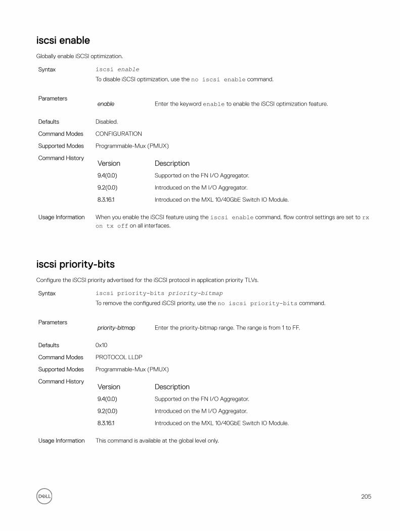
iscsi enableGlobally enable iSCSI optimization.
Syntax iscsi enableTo disable iSCSI optimization, use the no iscsi enable command.
Parametersenable Enter the keyword enable to enable the iSCSI optimization feature.
Defaults Disabled.
Command Modes CONFIGURATION
Supported Modes Programmable-Mux (PMUX)
Command HistoryVersion Description
9.4(0.0) Supported on the FN I/O Aggregator.
9.2(0.0) Introduced on the M I/O Aggregator.
8.3.16.1 Introduced on the MXL 10/40GbE Switch IO Module.
Usage Information When you enable the iSCSI feature using the iscsi enable command, flow control settings are set to rx on tx off on all interfaces.
iscsi priority-bitsConfigure the iSCSI priority advertised for the iSCSI protocol in application priority TLVs.
Syntax iscsi priority-bits priority-bitmapTo remove the configured iSCSI priority, use the no iscsi priority-bits command.
Parameterspriority-bitmap Enter the priority-bitmap range. The range is from 1 to FF.
Defaults 0x10
Command Modes PROTOCOL LLDP
Supported Modes Programmable-Mux (PMUX)
Command HistoryVersion Description
9.4(0.0) Supported on the FN I/O Aggregator.
9.2(0.0) Introduced on the M I/O Aggregator.
8.3.16.1 Introduced on the MXL 10/40GbE Switch IO Module.
Usage Information This command is available at the global level only.
205

iscsi profile-compellentConfigure the auto-detection of Dell Compellent arrays on a port.
Syntax iscsi profile-compellentDefaults Dell Compellent disk arrays are not detected.
Command Modes INTERFACE
Supported Modes Programmable-Mux (PMUX)
Command HistoryVersion Description
9.4(0.0) Supported on the FN I/O Aggregator.
9.2(0.0) Introduced on the M I/O Aggregator.
8.3.16.1 Introduced on the MXL 10/40GbE Switch IO Module.
iscsi target portConfigure the iSCSI target ports and optionally, the IP addresses on which iSCSI communication is monitored.
Syntax iscsi target port [tcp-port-2...tcp-port-16]ip-address [ip-address]To remove the configured iSCSI target ports or IP addresses, use the no iscsi target port command.
Parameterstcp-port-2...tcpport- 16
Enter the tcp-port number of the iSCSI target ports. The tcp-port-n is the TCP
port number or a list of TCP port numbers on which the iSCSI target listens to requests. Separate port numbers with a comma. The default is 860, 3260.
ip-address (Optional) Enter the ip-address that the iSCSI monitors. The ip-address specifies the IP address of the iSCSI target.
Defaults 860, 3260
Command Modes CONFIGURATION
Supported Modes Programmable-Mux (PMUX)
Command HistoryVersion Description
9.4(0.0) Supported on the FN I/O Aggregator.
9.2(0.0) Introduced on the M I/O Aggregator.
8.3.16.1 Introduced on the MXL 10/40GbE Switch IO Module
Usage Information You can configure up to 16 target TCP ports on the switch in one command or multiple commands.
When you use the no iscsi target port command and the TCP port you wish to delete is one bound
to a specific IP address, the IP address value must be included in the command.
206

show iscsiDisplay the currently configured iSCSI settings.
Syntax show iscsiCommand Modes
• EXEC
• EXEC Privilege
Supported Modes All Modes
Command HistoryVersion Description
9.4(0.0) Supported on the FN I/O Aggregator.
8.3.17.0 Supported on the M I/O Aggregator.
Example Dell#show iscsiiSCSI is enablediSCSI session monitoring is enablediSCSI COS : dot1p is 4 no-remarkSession aging time: 10Maximum number of connections is 256------------------------------------------------iSCSI Targets and TCP Ports:------------------------------------------------TCP Port Target IP Address3260860Dell#
Related Commands• show iscsi sessions — displays information on active iSCSI sessions on the switch that have been
established since the last reload.
• show iscsi sessions detailed — displays detailed information on active iSCSI sessions on the switch.
show iscsi sessionsDisplay information on active iSCSI sessions on the switch that have been established since the last reload.
Syntax show iscsi sessionsCommand Modes
• EXEC
• EXEC Privilege
Supported Modes All Modes
Command HistoryVersion Description
9.4(0.0) Supported on the FN I/O Aggregator.
8.3.17.0 Supported on the M I/O Aggregator.
Example Dell# show iscsi sessionsSession 0:
207

Target: iqn.2001-05.com.equallogic:0-8a0906-0e70c2002-10a0018426a48c94-iom010Initiator: iqn.1991-05.com.microsoft:win-x9l8v27yajgISID: 400001370000
Session 1:
Target: iqn.2001-05.com.equallogic:0-8a0906-0f60c2002-0360018428d48c94-iom011Initiator: iqn.1991-05.com.microsoft:win-x9l8v27yajgISID: 400001370000.
Related Commands• show iscsi — displays the currently configured iSCSI settings.
• show iscsi sessions detailed — displays detailed information on active iSCSI sessions on the switch.
show iscsi sessions detailedDisplays detailed information on active iSCSI sessions on the switch.
Syntax show iscsi sessions detailed [session isid]Parameters
isid Enter the session’s iSCSi ID to display detailed information on specified iSCSi session.
Command Modes• EXEC
• EXEC Privilege
Supported Modes All Modes
Command HistoryVersion Description
9.4(0.0) Supported on the FN I/O Aggregator.
8.3.17.0 Supported on the M I/O Aggregator.
Example Dell# show iscsi sessions detailedSession 0 :-----------------------------------------------------------------------------Target:iqn.2010-11.com.ixia:ixload:iscsi-TG1Initiator:iqn.2010-11.com.ixia.ixload:initiator-iscsi-2cUp Time:00:00:01:28(DD:HH:MM:SS)Time for aging out:00:00:09:34(DD:HH:MM:SS)ISID:806978696102Initiator Initiator Target Target ConnectionIP Address TCP Port IP Address TCPPort ID10.10.0.44 33345 .10.0.101 3260 0Session 1 :-----------------------------------------------------------------------------Target:iqn.2010-11.com.ixia:ixload:iscsi-TG1Initiator:iqn.2010-11.com.ixia.ixload:initiator-iscsi-35Up Time:00:00:01:22(DD:HH:MM:SS)Time for aging out:00:00:09:31(DD:HH:MM:SS)ISID:806978696102Initiator Initiator Target Target ConnectionIP Address TCP Port IP Address TCPPort ID10.10.0.53 33432 10.10.0.101 3260 0
208

Related Commands• show iscsi — displays the currently configured iSCSI settings.
• show iscsi sessions — displays information on active iSCSI sessions on the switch that have been established since the last reload.
209

14Isolated NetworksThis chapter describes the isolated networks commands in the Dell Networking OS.
io-aggregator isolated-network vlanEnable the isolated-network functionality for a particular VLAN or a set of VLANs.
Syntax [no] io-aggregator isolated-network vlan vlan-rangeParameters isolated-
networkSpecify an isolated network to be configured
vlan vlan-range
Enter the keyword vlan followed by the member VLANs using VLAN IDs (separated by commas), a range of VLAN IDs (separated by a hyphen), a single VLAN ID, or a combination. For example: VLAN IDs (comma-separated): 3, 4, 6. Range (hyphen-separated): 5-10. Combination: 3, 4, 5-10, 8.
Defaults Not configured.
Command Modes CONFIGURATION
Usage Information To add more VLANs into an isolated network, you can enter this same command at any later point. The VLANs specified are appended to the existing set of VLANs. To remove a VLAN or a set of VLANs from an isolated network, use the no form of command.
Supported Modes All Modes
Command HistoryVersion Description
9.5(0.0) Supported on the FN I/O Aggregator.
9.5(0.0) Supported on the M I/O Aggregator.
Example Dell(conf)#io-aggregator isolated-network vlan 5-10
show io-aggregator isolated-networks Display the VLANs that are configured to be part of an isolated network on an Aggregator.
Syntax show io-aggregator isolated-networksParameters isolated-
networksSpecify an isolated network to be configured
210

vlan vlan-range
Enter the keyword vlan followed by the member VLANs using VLAN IDs (separated by commas), a range of VLAN IDs (separated by a hyphen), a single VLAN ID, or a combination. For example: VLAN IDs (comma-separated): 3, 4, 6. Range (hyphen-separated): 5-10. Combination: 3, 4, 5-10, 8.
Defaults None
Command Modes EXEC Privilege
Usage Information This command is used to show the isolated-network feature status and the VLANs configured for this feature. Show running-config will save this command under io-aggregator.
Supported Modes All Modes
Command HistoryVersion Description
9.5(0.0) Supported on the FN I/O Aggregator.
9.5(0.0) Supported on the M I/O Aggregator.
Example Dell#show io-aggregator isolated-networksIsolated Network Enabled VLANs : 5-10
211

15Link Aggregation Control Protocol (LACP)This chapter contains commands for Dell Networking’s implementation of the link aggregation control protocol (LACP) for the creation of dynamic link aggregation groups (LAGs — called port-channels in Dell Networking OS parlance).
auto-lag enableEnable auto-lag on a server facing port.
Syntax auto-lag enableTo disable the auto-lag use the no auto-lag enable command.
When disabled, the server port associated in a LAG is removed and the LAG itself gets removed. Any LACPDUs received on the server port are discarded.
Defaults Enabled
Command Modes INTERFACE
Supported Modes Standalone, Stacking, VLT
Command HistoryVersion Description
9.6(0.0) Supported on the FN I/O Aggregator
9.6(0.0) Supported on the M I/O Aggregator.
clear lacp countersClear Port Channel counters.
Syntax clear lacp port-channel-number countersParameters
port-channel-number
Enter a port-channel number:
The range is from 1 to 128.
Command Modes EXEC
EXEC Privilege
Supported Modes All Modes
212

Command HistoryVersion Description
9.4(0.0) Supported on the FN I/O Aggregator.
8.3.17.0 Supported on the M I/O Aggregator.
Related Commands show lacp — displays the LACP configuration.
debug lacpDebug LACP (events).
Syntax debug lacp [pdu interface [in | out]]To disable LACP debugging, use the no debug lacp [pdu interface [in | out]] command.
Parameterspdu in | out (OPTIONAL) Enter the keyword pdu to debug the LACP Protocol Data Unit
information. Optionally, enter an in or out parameter to:
• Receive enter in• Transmit enter out
interface in | out Enter the following keywords and slot/port or number information:
• For a Ten-Gigabit Ethernet interface, enter the keyword TenGigabitEthernet followed by the slot/port information.
Defaults none
Command Modes EXEC
EXEC Privilege
Supported Modes All Modes
Command HistoryVersion Description
9.4(0.0) Supported on the FN I/O Aggregator.
io-aggregator auto-lag enableEnable auto-lag globally on the server facing ports
Syntax io-aggregator auto-lag enableTo disable the auto-lag, use the no io-aggregator auto-lag enable command.
When disabled, all the server ports associated in a LAG are removed and the LAG itself gets removed. Any LACPDUs received on the server ports are discarded.
213

Defaults Enabled
Command Modes CONFIGURATION
Supported Modes Standalone, Stacking, VLT
Command HistoryVersion Description
9.6(0.0) Supported on the FN I/O Aggregator.
9.6(0.0) Supported on the M I/O Aggregator.
Related Commands show io-aggregator auto-lag status—displays global information on the auto-lag status.
lacp link-fallback memberEnable the LACP link fallback member feature.
Syntax lacp link-fallback member-independent port-channel 128To disable the LACP link fallback member, use theno lacp link-fallback member-independent port-channel 128 command.
Command Modes INTERFACE
Supported Modes Standalone, Stacking
Command History This guide is platform-specific. For command information about other platforms, refer to the relevant Dell Networking OS Command Reference Guide.
The following is a list of the Dell Networking OS version history for this command.
Version Description
9.7(0.0) Introduced on the M I/O Aggregator and FN I/O Aggregator.
lacp long-timeoutConfigure a long timeout period (30 seconds) for an LACP session.
Syntax lacp long-timeoutTo reset the timeout period to a short timeout (1 second), use the no lacp long-timeout command.
Defaults 1 second
Command Modes INTERFACE (conf-if-po-number)
Supported Modes Programmable-Mux (PMUX)
Command HistoryVersion Description
9.4(0.0) Supported on the FN I/O Aggregator.
9.2(0.0) Introduced on the M I/O Aggregator.
214

Version Description
8.3.16.1 Introduced on the MXL 10/40GbE Switch IO Module.
Usage Information This command applies to dynamic port-channel interfaces only. When applied on a static port-channel, this command has no effect.
lacp port-priorityTo influence which ports will be put in Standby mode when there is a hardware limitation that prevents all compatible ports from aggregating, configure the port priority.
Syntax lacp port-priority priority-valueTo return to the default setting, use the no lacp port-priority priority-value command.
Parameterspriority-value Enter the port-priority value. The higher the value number, the lower the priority.
The range is from 1 to 65535. The default is 32768.
Defaults 32768
Command Modes INTERFACE
Supported Modes Programmable-Mux (PMUX)
Command HistoryVersion Description
9.4(0.0) Supported on the FN I/O Aggregator.
9.2(0.0) Introduced on the M I/O Aggregator.
8.3.16.1 Introduced on the MXL 10/40GbE Switch IO Module.
port-channel modeConfigure the LACP port channel mode.
Syntax port-channel number mode [active] [passive] [off]Parameters
number Enter the keywords number then a number.
active Enter the keyword active to set the mode to the active state.
NOTE: LACP modes are defined in Usage Information.
passive Enter the keyword passive to set the mode to the passive state.
NOTE: LACP modes are defined in Usage Information.
off Enter the keyword off to set the mode to the off state.
215

NOTE: LACP modes are defined in Usage Information.
Defaults off
Command Modes INTERFACE
Supported Modes Programmable-Mux (PMUX)
Command HistoryVersion Description
9.4(0.0) Supported on the FN I/O Aggregator.
9.2(0.0) Introduced on the M I/O Aggregator.
8.3.16.1 Introduced on the MXL 10/40GbE Switch IO Module.
Usage Information LACP Modes
Mode Function
active An interface is in an active negotiating state in this mode. LACP runs on any link configured in the active state and also automatically initiates negotiation with other ports by initiating LACP packets.
passive An interface is not in an active negotiating state in this mode. LACP runs on any link configured in the passive state. Ports in a passive state respond to negotiation requests from other ports that are in active states. Ports in a passive state respond to LACP packets
off An interface cannot be part of a dynamic port channel in off mode. LACP does not run on a port configured in off mode.
port-channel-protocol lacpEnable LACP on any LAN port.
Syntax port-channel-protocol lacpTo disable LACP on a LAN port, use the no port-channel-protocol lacp command.
Command Modes INTERFACE
Supported Modes Programmable-Mux (PMUX)
Command HistoryVersion Description
9.4(0.0) Supported on the FN I/O Aggregator.
Example Dell(conf)#interface TenGigabitethernet 0/5Dell(conf-if-te-0/5)#no shutdownDell(conf-if-te-0/5)#port-channel-protocol lacpDell(conf-if-te-0/5-lacp)#port-channel 32 mode active...Dell(conf)#interface TenGigabitethernet 0/6Dell(conf-if-te-0/6)#no shutdown
216

Dell(conf-if-te-0/6)#port-channel-protocol lacpDell(conf-if-te-0/6-lacp)#port-channel 32 mode active
show interfaces port-channelDisplay information on configured Port Channel groups.
Syntax show interfaces port-channel [channel-number] [brief| description]Parameters
channel-number For a Port Channel interface, enter the keyword port-channel followed by a
number. The range is from 1 to 128.
brief (OPTIONAL) Enter the keyword brief to display only the port channel number,
the state of the port channel, and the number of interfaces in the port channel.
description (OPTIONAL) Enter the keyword description to display interface information with description.
Command Modes• EXEC
• EXEC Privilege
Supported Modes All Modes
Command HistoryVersion Description
9.7(0.0) Introduced on the M I/O Aggregator.
9.4(0.0) Supported on the FN I/O Aggregator.
Usage Information The following describes the show interfaces port-channel command shown in the following
example.
Field Description
Port-Channel 1... Displays the status of LAG. In the Example, the status of the LAG, LAG fate-sharing group (“Failover-group”) is listed.
Hardware is... Displays the interface’s hardware information and its assigned MAC address.
Port-channel is part...
Indicates whether the LAG is part of a LAG fate-sharing group (“Failover-group”).
Internet address... States whether an IP address is assigned to the interface. If an IP address is assigned, that address is displayed.
MTU 1554... Displays link and IP MTU.
LineSpeed Displays the interface’s line speed. For a port channel interface, it is the line speed of the interfaces in the port channel.
Members in this... Displays the interfaces belonging to this port channel.
ARP type:... Displays the ARP type and the ARP timeout value for the interface.
Last clearing... Displays the time when the show interfaces counters were cleared.
Queueing strategy. States the packet queuing strategy. FIFO means first in first out.
217

Field Description
packets input... Displays the number of packets and bytes into the interface.
Input 0 IP packets... Displays the number of packets with IP headers, VLAN tagged headers, and MPLS headers. The number of packets may not add correctly because a VLAN tagged IP packet counts as both a VLAN packet and an IP packet.
0 64-byte... Displays the size of packets and the number of those packets entering that interface. This information is displayed over two lines.
Received 0... Displays the type and number of errors or other specific packets received. This information is displayed over three lines.
Output 0... Displays the type and number of packets sent out the interface. This information is displayed over three lines.
Rate information... Displays the traffic rate information into and out of the interface. Traffic rate is displayed in bits and packets per second.
Time since... Displays the time since the last change in the configuration of this interface.
Example (EtherScale)
Dell#show interfaces port-channelPort-channel 1 is down, line protocol is downHardware address is 00:1e:c9:f1:00:05, Current address is 00:1e:c9:f1:00:05Interface index is 1107755009Minimum number of links to bring Port-channel up is 1Internet address is not setMode of IP Address Assignment : NONEDHCP Client-ID :lag1001ec9f10005MTU 12000 bytes, IP MTU 1500 bytesLineSpeed autoMembers in this channel:ARP type: ARPA, ARP Timeout 04:00:00Last clearing of "show interface" counters 03:28:00Queueing strategy: fifoInput Statistics:0 packets, 0 bytes0 64-byte pkts, 0 over 64-byte pkts, 0 over 127-byte pkts0 over 255-byte pkts, 0 over 511-byte pkts, 0 over 1023-byte pkts0 Multicasts, 0 Broadcasts0 runts, 0 giants, 0 throttles0 CRC, 0 overrun, 0 discardedOutput Statistics:0 packets, 0 bytes, 0 underruns0 64-byte pkts, 0 over 64-byte pkts, 0 over 127-byte pkts0 over 255-byte pkts, 0 over 511-byte pkts, 0 over 1023-byte pkts0 Multicasts, 0 Broadcasts, 0 Unicasts0 throttles, 0 discarded, 0 collisions
User Information The following describes the show interfaces port-channel brief command shown in the
following example.
Field Description
LAG Lists the port channel number.
Mode Lists the mode:
• L3 — for Layer 3
• L2 — for Layer 2
Status Displays the status of the port channel.
218

Field Description• down — if the port channel is disabled (shutdown)
• up — if the port channel is enabled (no shutdown)
Uptime Displays the age of the port channel in hours:minutes:seconds.
Ports Lists the interfaces assigned to this port channel.
(untitled) Displays the status of the physical interfaces (up or down).
• In Layer 2 port channels, an * (asterisk) indicates which interface is the primary port of the port channel. The primary port sends out interface PDU.
• In Layer 3 port channels, the primary port is not indicated.
Example Dell#show int po briCodes: L - LACP Port-channel O - OpenFlow Controller Port-channel A - Auto Port-channel I - Internally LaggedLAG Mode Status Uptime Ports L 128 L3 down 00:00:00 Dell#To indicate the LACP fallback, Internally lagged is added to the list. When the LAG auto-configures
itself, the LAG status describes as ‘I’.
Related Commands show lacp — displays the LACP matrix.
show io-aggregator auto-lag statusDisplays global information on the auto-lag status.
Syntax show io-aggregator auto-lag statusCommand Modes EXEC
Supported Modes Standalone, Stacking, VLT
Command HistoryVersion Description
9.6(0.0) Supported on the FN I/O Aggregator.
9.6(0.0) Supported on the M I/O Aggregator.
Example Dell-ct-mxl-1-b1(conf)#do show io-aggregator auto-lag status Auto LAG creation on server port(s) is disabled
219

show lacpDisplays the LACP matrix.
Syntax show lacp port-channel-number [sys-id | counters]Parameters
port-channel-number
Enter a port-channel number:
The range is from 1 to 128.
sys-id (OPTIONAL) Enter the keywords sys-id and the value that identifies a system.
counters (OPTIONAL) Enter the keyword counters to display the LACP counters.
Command Modes• EXEC
• EXEC Privilege
Supported Modes All Modes
Command HistoryVersion Description
9.4(0.0) Supported on the FN I/O Aggregator.
8.3.17.0 Supported on the M I/O Aggregator.
Example (Port-Channel-Number)
Dell#show lacp 128Port-channel 1 admin up, oper up, mode lacpActor System ID:Priority 32768, Address 0001.e800.a12bPartner System ID:Priority 32768, Address 0001.e801.45a5 Actor Admin Key 1, Oper Key 1, Partner Oper Key 1 LACP LAG 1 is an aggregatable link
A-Active LACP, B-Passive LACP, C-Short Timeout, D-Long TimeoutE-Aggregatable Link, F-Individual Link, G-IN_SYNC, H-OUT_OF_SYNCI-Collection enabled, J-Collection disabled, K-Distribution enabled L-Distribution disabled,M-Partner Defaulted, N-Partner Non-defaulted, O-Receiver is in expired state,P-Receiver is not in expired state
Port Te 0/1 is enabled, LACP is enabled and mode is lacp Actor Admin: State ACEHJLMP Key 1 Priority 128 Oper: State ACEGIKNP Key 1 Priority 128 Partner Admin: State BDFHJLMP Key 0 Priority 0 Oper: State BCEGIKNP Key 1 Priority 128Dell#
Example (Sys-id) Dell#show lacp 1 sys-idActor System ID: Priority 32768, Address 0001.e800.a12bPartner System ID: Priority 32768, Address 0001.e801.45a5
Dell#
Example (Counter) Dell#show lacp 1 counters---------------------------------------------------- LACP PDU Marker PDU Unknown IllegalPort Xmit Recv Xmit Recv Pkts Rx Pkts Rx-----------------------------------------------------TenGig 0/1 200 200 0 0 0 0Dell#
220

Related Commands clear lacp counters — Clears the LACP counters.
show interfaces port-channel — Displays the information on configured Port Channel groups.
show link-bundle-distribution port-channelDisplay the traffic-handling and utilization of the member interfaces of the port channel.
Syntax show link-bundle-distribution port-channelCommand Modes EXEC
EXEC Privilege
Supported Modes All Modes
Command HistoryVersion Description
9.4(0.0) Supported on the FN I/O Aggregator.
Usage Information The following table describes the output fields of this show command:
Field Description
Link-bundle trigger threshold Threshold value that is the checkpoint, exceeding which the link bundle is marked as being overutilized and alarm is generated
LAG bundle number Number of the LAG bundle
Utilization (In Percent) Traffic usage in percentage of the packets processed by the port channel
Alarm State Indicates whether an alarm is generated if overutilization of the port channel occurred. Possible values are Active and Inactive
Interface Slot and port number, and the type of the member interface of the port channel
Line Protocol Indicates whether the interface is administratively up or down
Utilization (In Percent) Traffic usage in percentage of the packets processed by the particular member interface
Example Dell#show link-bundle-distribution port-channelLink-bundle trigger threshold - 60
LAG bundle - 1 Utilization[In Percent] - 0 Alarm State - Inactive
Interface Line Protocol Utilization[In Percent]Te 0/5 Up 0
221

show port-channel-flowDisplay an egress port in a given port-channel flow.
Syntax show port-channel-flow port-channel number incoming-interface interface { src-mac address dest-mac address {vlan vlanid | ether-type }} [ src-ip address dest-ip address ] [ src-port number dest-port number ]
Parametersport-channel number
Enter the keywords port-channel then the number of the port channel to
display flow information. The range is from 1 to 128.
incoming-interface interface
Enter the keywords incoming-interface then the interface type and slot/
port or number information:
• For a 10-Gigabit Ethernet interface, enter the keyword TenGigabitEthernet then the slot/port information.
src-mac address Enter the keywords src-mac then the MAC source address in the
nn:nn:nn:nn:nn:nn format.
dest-macaddress Enter the keywords dest-mac then the MAC destination address in the
nn:nn:nn:nn:nn:nn format.
vlan vlan-id Enter the keyword vlan then the VLAN ID. The range is from 1 to 4094.
ether-type Enter the keywords ether-type then the ether-value in the XX:XX format.
src-ip address Enter the keywords src-ip then the IP source address in IP address format.
dest-ip address Enter the keywords dest-ip then the IP destination address in IP address format.
src-port number Enter the keywords src-port then the source port number. The range is from 1
to 65536. The default is None.
dest-port number Enter the keywords dest-port then the destination port number. The range is
from 1 to 65536. The default is None.
Command Modes EXEC
Supported Modes All Modes
Command HistoryVersion Description
9.4(0.0) Supported on the FN I/O Aggregator.
8.3.17.0 Supported on the M I/O Aggregator.
Usage Information Because this command calculates based on a Layer 2 hash algorithm, use this command to display flows for switched Layer 2 packets, not for routed packets (use the show ip flow command to display routed
packets).
The show port-channel-flow command returns the egress port identification in a given port-channel
if a valid flow is entered. A mismatched flow error occurs if MAC-based hashing is configured for a Layer 2 interface and you are trying to display a Layer 3 flow.
The output displays three entries:
• Egress port for unfragmented packets.
• In the event of fragmented packets, the egress port of the first fragment.
222

• In the event of fragmented packets, the egress port of the subsequent fragments.
NOTE: In the show port-channel–flow command output, the egress port for an unknown
unicast, multicast, or broadcast traffic is not displayed.
223

16Layer 2This chapter describes commands to configure Layer 2 features.
This chapter contains the following sections:
• MAC Addressing Commands
• Virtual LAN (VLAN) Commands
MAC Addressing CommandsThe following commands are related to configuring, managing, and viewing MAC addresses:
• clear mac-address-table dynamic
• mac-address-table aging-time
• mac-address-table static
• mac-address-table station-move refresh-arp
• show cam mac stack-unit
• show mac-address-table
Virtual LAN (VLAN) CommandsThe following commands configure and monitor virtual local area networks (VLANs). VLANs are a virtual interface and use many of the same commands as physical interfaces.
For more information, also refer to Virtual LAN (VLAN) Commands.
clear mac-address-table dynamicClear the MAC address table of all MAC addresses learned dynamically.
Syntax clear mac-address-table dynamic {address mac-address | all | interface interface | vlan vlan-id}
Parametersaddress mac-address
Enter the keyword address followed by a MAC address in nn:nn:nn:nn:nn:nn
format.
all Enter the keyword all to delete all MAC address entries in the MAC address table.
interface interface Enter the following keywords and slot/port or number information:
224
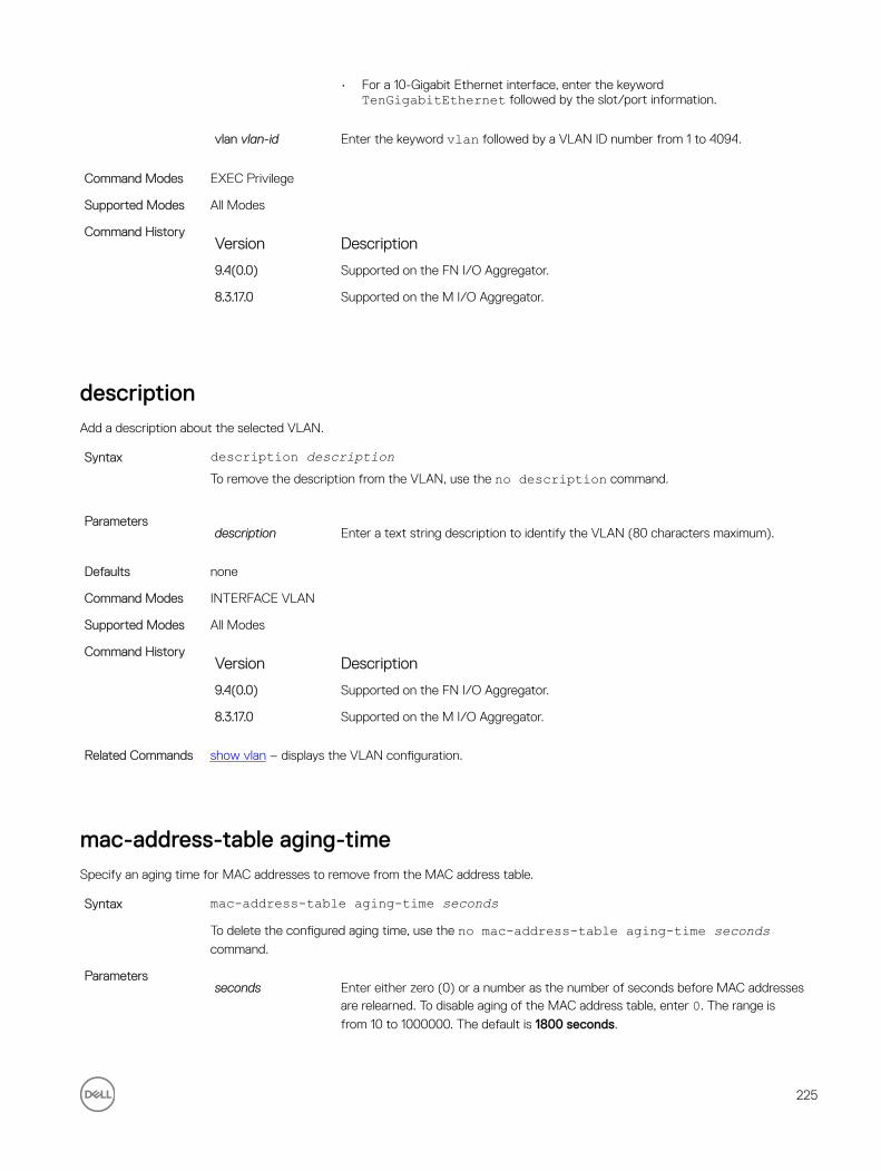
• For a 10-Gigabit Ethernet interface, enter the keyword TenGigabitEthernet followed by the slot/port information.
vlan vlan-id Enter the keyword vlan followed by a VLAN ID number from 1 to 4094.
Command Modes EXEC Privilege
Supported Modes All Modes
Command HistoryVersion Description
9.4(0.0) Supported on the FN I/O Aggregator.
8.3.17.0 Supported on the M I/O Aggregator.
descriptionAdd a description about the selected VLAN.
Syntax description descriptionTo remove the description from the VLAN, use the no description command.
Parametersdescription Enter a text string description to identify the VLAN (80 characters maximum).
Defaults none
Command Modes INTERFACE VLAN
Supported Modes All Modes
Command HistoryVersion Description
9.4(0.0) Supported on the FN I/O Aggregator.
8.3.17.0 Supported on the M I/O Aggregator.
Related Commands show vlan – displays the VLAN configuration.
mac-address-table aging-timeSpecify an aging time for MAC addresses to remove from the MAC address table.
Syntax mac-address-table aging-time secondsTo delete the configured aging time, use the no mac-address-table aging-time seconds command.
Parametersseconds Enter either zero (0) or a number as the number of seconds before MAC addresses
are relearned. To disable aging of the MAC address table, enter 0. The range is
from 10 to 1000000. The default is 1800 seconds.
225

Defaults 1800 seconds
Command Modes CONFIGURATION
Supported Modes Programmable-Mux (PMUX)
Command HistoryVersion Description
9.4(0.0) Supported on the FN I/O Aggregator.
9.2(0.0) Introduced on the M I/O Aggregator.
mac-address-table staticAssociate specific MAC or hardware addresses to an interface and virtual local area networks (VLANs).
Syntax mac-address-table static mac-address output interface vlan vlan-idTo remove a MAC address, use the no mac-address-table static mac-address output interface vlan vlan-id command.
Parametersmac-address Enter the 48-bit hexadecimal address in nn:nn:nn:nn:nn:nn format.
output interface Enter the keyword output then one of the following interfaces for which traffic is
forwarded:
• For a Port Channel interface, enter the keywords port-channel then a number. The range is from 1 to 128.
• For a 10-Gigabit Ethernet interface, enter the keyword TenGigabitEthernet then the slot/port information.
vlan vlan-id Enter the keyword vlan then a VLAN ID number from 1 to 4094.
Defaults Not configured.
Command Modes CONFIGURATION
Supported Modes Programmable-Mux (PMUX)
Command HistoryVersion Description
9.4(0.0) Supported on the FN I/O Aggregator.
mac-address-table station-move refresh-arpEnsure that address resolution protocol (ARP) refreshes the egress interface when a station move occurs due to a topology change.
Syntax [no] mac-address-table station-move refresh-arpDefaults none
Command Modes CONFIGURATION
226

Supported Modes Programmable-Mux (PMUX)
Command HistoryVersion Description
9.4(0.0) Supported on the FN I/O Aggregator.
9.2(0.0) Introduced on the M I/O Aggregator.
8.3.16.1 Introduced on the MXL 10/40GbE Switch IO Module.
Usage Information For details about using this command, refer to the “NIC Teaming” section of the Layer 2 chapter in the Dell Networking OS Configuration Guide.
show cam mac stack-unitDisplay the content addressable memory (CAM) size and the portions allocated for MAC addresses and for MAC ACLs.
Syntax show cam mac stack-unit unit_number port-set port-pipe count [vlan vlan-id] [interface interface]
Parametersstack-unit unit_number
(REQUIRED) Enter the keyword stack-unit followed by a stack member
number to select the stack unit for which to gather information. The range is 0 to 5.
port-set port-pipe (REQUIRED) Enter the keywords port-set followed by a Port-Pipe number to
select the Port-Pipe for which to gather information. The range is 0.
address mac-addr (OPTIONAL) Enter the keyword address followed by a MAC address in the
nn:nn:nn:nn:nn:nn format to display information on that MAC address.
dynamic (OPTIONAL) Enter the keyword dynamic to display only those MAC addresses
learned dynamically by the switch.
static (OPTIONAL) Enter the keyword static to display only those MAC address
specifically configured on the switch.
interface interface (OPTIONAL) Enter the keyword interface followed by the interface type, slot
and port information:
• For a 10-Gigabit Ethernet interface, enter the keyword TenGigabitEthernet followed by the slot/port information.
vlan vlan-id (OPTIONAL) Enter the keyword vlan followed by the VLAN ID to display the
MAC address assigned to the VLAN. The range is from 1 to 4094.
Command Modes• EXEC
• EXEC Privilege
Supported Modes All Modes
Command HistoryVersion Description
9.4(0.0) Supported on the FN I/O Aggregator.
227

Version Description
8.3.17.0 Supported on the M I/O Aggregator.
show mac-address-tableDisplay the MAC address table.
Syntax show mac-address-table [dynamic | static] [address mac-address | interface interface | vlan vlan-id] [count [vlan vlan-id] [interface interface-type [slot [/port]]]]
Parametersdynamic (OPTIONAL) Enter the keyword dynamic to display only those MAC addresses
the switch dynamically learns. Optionally, you can also add one of these combinations: address/mac-address, interface/interface, or vlan vlan-id.
static (OPTIONAL) Enter the keyword static to display only those MAC addresses
specifically configured on the switch. Optionally, you can also add one of these combinations: address/mac-address, interface/interface, or vlan vlan-id.
address mac-address
(OPTIONAL) Enter the keyword address then a MAC address in the
nn:nn:nn:nn:nn:nn format to display information on that MAC address.
interface interface (OPTIONAL) Enter the keyword interface then the interface type, slot and port
information:
• For a Port Channel interface, enter the keywords port-channel then a number. The range is from 1 to 128.
• For a 10-Gigabit Ethernet interface, enter the keyword TenGigabitEthernet then the slot/port information.
interface interface-type
(OPTIONAL) Instead of entering the keyword interface then the interface type,
slot and port information, as above, you can enter the interface type, then just a slot number.
vlan vlan-id (OPTIONAL) Enter the keyword vlan then the VLAN ID to display the MAC
address assigned to the VLAN. The range is 1 to 4094.
count (OPTIONAL) Enter the keyword count, then optionally, by an interface or VLAN
ID, to display total or interface-specific static addresses, dynamic addresses, and MAC addresses in use.
Command Modes• EXEC
• EXEC Privilege
Supported Modes Programmable-Mux (PMUX)
Command HistoryVersion Description
9.4(0.0) Supported on the FN I/O Aggregator.
228

Version Description
9.2(0.0) Introduced on the M I/O Aggregator.
Usage Information The following describes the show mac-address-table command shown in the following example.
Column Heading Description
VlanId Displays the VLAN ID number.
Mac Address Displays the MAC address in nn:nn:nn:nn:nn:nn format.
Type Lists whether the MAC address was manually configured (Static), learned dynamically (Dynamic), or associated with a specific port (Sticky).
Interface Displays the interface type and slot/port information. The following abbreviations describe the interface types:
• gi — Gigabit Ethernet then a slot/port.
• po — Port Channel then a number. The range is from 1 to 255 for TeraScale.
• so —SONET then a slot/port.
• te — 10 Gigabit Ethernet then a slot/port.
State Lists if the MAC address is in use (Active) or not in use (Inactive).
Example Dell#show mac-address-tableVlanId Mac Address Type Interface State20 00:00:c9:ad:f6:12 Dynamic Te 0/3 ActiveDell#
Usage Information The following describes the show mac-address-table command shown in the following example.
Column Heading Description
VlanId Displays the VLAN ID number.
Mac Address Displays the MAC address in nn:nn:nn:nn:nn:nn format.
Type Lists whether the MAC address was manually configured (Static), learned (Dynamic), or associated with a specific port (Sticky). An (N) indicates that the specified MAC address has been learnt by a neighbor and is synced to the node.
Interface Displays the interface type and slot/port information. The following abbreviations describe the interface types:
• gi — Gigabit Ethernet then a slot/port
• po — Port Channel then a number. The range is from 1 to 255. \
• so — SONET then a slot/port.
• te — 10–Gigabit Ethernet then a slot/port.
State Lists if the MAC address is in use (Active) or not in use (Inactive).
The following describes the show mac-address-table count command shown in the following
example.
Line Beginning With
Description
MAC Entries... Displays the number of MAC entries learned per VLAN.
229

Line Beginning With
Description
Dynamic Address... Lists the number of dynamically learned MAC addresses.
Static Address... Lists the number of user-defined MAC addresses.
Total MAC... Lists the total number of MAC addresses the switch uses.
Example (Count) Dell#show mac-address-table countMAC Entries for all vlans :Dynamic Address Count : 5Static Address (User-defined) Count : 0Total MAC Addresses in Use: 5Dell#
230
17Link Layer Discovery Protocol (LLDP)The link layer discovery protocol (LLDP) advertises connectivity and management from the local station to the adjacent stations on an IEEE 802 LAN. LLDP facilitates multi-vendor interoperability by using standard management tools to discover and make available a physical topology for network management. The Dell Networking OS implementation of LLDP is based on IEEE standard 801.1ab.
This chapter describes the LLDP commands.
The starting point for using LLDP is invoking LLDP with the protocol lldp command in either CONFIGURATION or INTERFACE
mode.
The information LLDP distributes is stored by its recipients in a standard management information base (MIB). You can access the information by a network management system through a management protocol such as simple network management protocol (SNMP).
For details about implementing LLDP/LLDP-MED, refer to the Link Layer Discovery Protocol chapter of the Dell PowerEdge FN I/O Aggregator Configuration Guide.
advertise dot3-tlvAdvertise dot3 TLVs (Type, Length, Value).
Syntax advertise dot3-tlv {max-frame-size}To remove advertised dot3-tlv, use the no advertise dot3-tlv {max-frame-size} command.
Parametersmax-frame-size Enter the keywords max-frame-size to advertise the dot3 maximum frame
size.
Defaults none
Command Modes CONFIGURATION (conf-lldp) and INTERFACE (conf-if-interface-lldp)
Supported Modes Programmable-Mux (PMUX)
Command HistoryVersion Description
9.4(0.0) Supported on the FN I/O Aggregator.
9.2(0.0) Introduced on the M I/O Aggregator.
8.3.16.1 Introduced on the MXL 10/40GbE Switch IO Module.
231

advertise management-tlvAdvertise management TLVs (Type, Length, Value).
Syntax advertise management-tlv {system-capabilities | system-description | system-name}To remove advertised management TLVs, use the no advertise management-tlv {system-capabilities | system-description | system-name} command.
Parameterssystem-capabilities Enter the keywords system-capabilities to advertise the system capabilities
TLVs to the LLDP peer.
system-description Enter the keywords system-description to advertise the system description
TLVs to the LLDP peer.
system-name Enter the keywords system-name to advertise the system name TLVs to the
LLDP peer.
Defaults none
Command Modes CONFIGURATION (conf-lldp)
Supported Modes Programmable-Mux (PMUX)
Command HistoryVersion Description
9.4(0.0) Supported on the FN I/O Aggregator.
8.3.16.1 Introduced on the M I/O Aggregator.
8.3.16.1 Introduced on the MXL 10/40GbE Switch IO Module.
Usage Information The command options system-capabilities, system-description, and system-name can be
invoked individually or together, in any sequence.
clear lldp countersClear LLDP transmitting and receiving counters for all physical interfaces or a specific physical interface.
Syntax clear lldp counters interfaceParameters
interface Enter the following keywords and slot/port or number information:
• For a 10-Gigabit Ethernet interface, enter the keyword tenGigabitEthernet followed by the slot/port information.
Defaults none
Command Modes EXEC Privilege
Supported Modes All Modes
232

Command HistoryVersion Description
9.4(0.0) Supported on the FN I/O Aggregator.
clear lldp neighborsClear LLDP neighbor information for all interfaces or a specific interface.
Syntax clear lldp neighbors {interface}Parameters
interface Enter the following keywords and slot/port or number information:
• For a 10-Gigabit Ethernet interface, enter the keyword TenGigabitEthernet then the slot/port information.
Defaults none
Command Modes EXEC Privilege
Supported Modes Programmable-Mux (PMUX)
Command HistoryVersion Descrition
9.4(0.0) Supported on the FN I/O Aggregator.
debug lldp interfaceEnable LLDP debugging to display timer events, neighbor additions or deletions, and other information about incoming and outgoing packets.
Syntax debug lldp interface {interface | all}{events | packet {brief | detail} {tx | rx | both}}To disable debugging, use the no debug lldp interface {interface | all}{events} {packet {brief | detail} {tx | rx | both}} command.
Parametersinterface Enter the following keywords and slot/port or number information:
• For a 10-Gigabit Ethernet interface, enter the keyword tenGigabitEthernet followed by the slot/port information.
all (OPTIONAL) Enter the keyword all to display information on all interfaces.
events (OPTIONAL) Enter the keyword events to display major events such as timer
events.
packet (OPTIONAL) Enter the keyword packet to display information regarding packets
coming in or going out.
brief (OPTIONAL) Enter the keyword brief to display brief packet information.
233

detail (OPTIONAL) Enter the keyword detail to display detailed packet information.
tx (OPTIONAL) Enter the keyword tx to display transmit-only packet information.
rx (OPTIONAL) Enter the keyword rx to display receive-only packet information.
both (OPTIONAL) Enter the keyword both to display both receive and transmit packet
information.
Defaults none
Command Modes EXEC Privilege
Supported Modes All Modes
Command HistoryVersion Description
9.4(0.0) Supported on the FN I/O Aggregator.
disableEnable or disable LLDP.
Syntax disableTo enable LLDP, use the no disable command.
Defaults Enabled, that is no disable.
Command Modes CONFIGURATION (conf-lldp) and INTERFACE (conf-if-interface-lldp)
Supported Modes Programmable-Mux (PMUX)
Command HistoryVersion Description
9.4(0.0) Supported on the FN I/O Aggregator.
9.2(0.0) Introduced on the M I/O Aggregator.
8.3.16.1 Introduced on the MXL 10/40GbE Switch IO Module.
Related Commands debug lldp interface — debugs LLDP.
helloConfigure the rate at which the LLDP control packets are sent to its peer.
Syntax hello secondsTo revert to the default, use the no hello seconds command.
234

Parametersseconds Enter the rate, in seconds, at which the control packets are sent to its peer. The
rate is from 5 to 180 seconds. The default is 30 seconds.
Defaults 30 seconds
Command Modes CONFIGURATION (conf-lldp) and INTERFACE (conf-if-interface-lldp)
Supported Modes Programmable-Mux (PMUX)
Command HistoryVersion Description
9.4(0.0) Supported on the FN I/O Aggregator.
9.2(0.0) Introduced on the M I/O Aggregator.
8.3.16.1 Introduced on the MXL 10/40GbE Switch IO Module.
multiplierSet the number of consecutive misses before LLDP declares the interface dead.
Syntax multiplier integerTo return to the default, use the no multiplier integer command.
Parametersinteger Enter the number of consecutive misses before the LLDP declares the interface
dead. The range is from 2 to 10.
Defaults 4 x hello
Command Modes CONFIGURATION (conf-lldp) and INTERFACE (conf-if-interface-lldp)
Supported Modes Programmable-Mux (PMUX)
Command HistoryVersion Description
9.4(0.0) Supported on the FN I/O Aggregator.
9.2(0.0) Introduced on the M I/O Aggregator.
8.3.16.1 Introduced on the MXL 10/40GbE Switch IO Module.
protocol lldp (Configuration)Enable LLDP globally on the switch.
Syntax protocol lldpTo disable LLDP globally on the chassis, use the no protocol lldp command.
Defaults Enabled.
Command Modes CONFIGURATION (conf-lldp)
235

Supported Modes All Modes
Command HistoryVersion Description
9.4(0.0) Supported on the FN I/O Aggregator.
8.3.17.0 Supported on the M I/O Aggregator.
protocol lldp (Interface)Enter the LLDP protocol in the INTERFACE mode.
Syntax [no] protocol lldpTo return to the global LLDP configuration mode, use the no protocol lldp command from Interface
mode.
Defaults Enabled
Command Modes INTERFACE (conf-if-interface-lldp)
Supported Modes All Modes
Command HistoryVersion Description
9.4(0.0) Supported on the FN I/O Aggregator.
8.3.17.0 Supported on the M I/O Aggregator.
Usage Information This command is available only in PMUX mode.
By default, protocol lldp is enabled, To disable, use the no protocol lldp command.
When you enter the LLDP protocol in the Interface context, it overrides global configurations. When you
execute the no protocol lldp from INTERFACE mode, interfaces begin to inherit the configuration
from global LLDP CONFIGURATION mode.
show lldp neighborsDisplay LLDP neighbor information for all interfaces or a specified interface.
Syntax show lldp neighbors [interface] [detail]Parameters
interface (OPTIONAL) Enter the following keywords and slot/port or number information:
• For a 10-Gigabit Ethernet interface, enter the keyword tenGigabitEthernet then the slot/port information.
detail (OPTIONAL) Enter the keyword detail to display all the TLV information, timers,
and LLDP tx and rx counters.
236

Defaults none
Command Modes EXEC Privilege
Supported Modes All Modes
Command HistoryVersion Description
9.4(0.0) Supported on the FN I/O Aggregator.
Usage Information Omitting the keyword detail displays only the remote chassis ID, Port ID, and host name.
Example Dell (conf-if-te-0/3)#do show lldp neighborsLoc PortID Rem Host Name Rem Port Id Rem Chassis Id--------------------------------------------------------------------Te 0/1 FTOS TenGigabitEthernet 0/5 00:01:e8:05:40:46Te 0/2 FTOS TenGigabitEthernet 0/6 00:01:e8:05:40:46Te 0/3 FTOS TenGigabitEthernet 0/7 00:01:e8:05:40:46Dell (conf-if-te-0/3)#
show lldp statisticsDisplays the LLDP statistical information.
Syntax show lldp statisticsDefaults none
Command Modes EXEC Privilege
Supported Modes All Modes
Command HistoryVersion Description
9.4(0.0) Supported on the FN I/O Aggregator.
8.3.17.0 Supported on the M I/O Aggregator.
Example Dell#show lldp statistics--------- LLDP GLOBAL STATISTICS ON CHASSIS ------------Total number of neighbors: 4Last table change time: 00:01:17, In ticks: 3859Total number of Table Inserts: 7Total number of Table Deletes: 3Total number of Table Drops: 0Total number of Table Age Outs: 0Dell#
237
18NPIV Proxy GatewayThe N-port identifier virtualization (NPIV) Proxy Gateway (NPG) feature provides FCoE-FC bridging capability on the FN I/O Aggregator with the FC Flex IO module switch, allowing server CNAs to communicate with SAN fabrics over the FN I/O Aggregator with the FC Flex IO module.
To configure the FN I/O Aggregator with the FC Flex IO module to operate as an NPIV proxy gateway, use the following commands:
dcb-mapCreate a DCB map to configure priority flow control (PFC) and enhanced transmission selection (ETS) on Ethernet ports that support converged Ethernet traffic. Apply the DCB map to an Ethernet interface.
Syntax dcb-map map-nameParameters
map-name Enter a DCB map name. The maximum number of alphanumeric characters is 32.
Defaults None. .
Command Modes CONFIGURATION
INTERFACE
Supported Modes Programmable-Mux (PMUX)
Command HistoryVersion Description
9.4(0.0) Supported on the FN I/O Aggregator.
9.3(0.0) Supported on the M I/O Aggregator.
Usage Information A DCB map is a template used to configure DCB parameters and apply them on converged Ethernet interfaces. DCB parameters include priority-based flow control (PFC) and enhanced traffic selection (ETS).
To display the PFC and ETS settings in DCB maps, enter the show qos dcb-map command.
Use the dcb-map command to create a DCB map to specify PFC and ETS settings and apply it on Ethernet
ports. After you apply a DCB map to an interface, the PFC and ETS settings in the map are applied when the Ethernet port is enabled. DCBx is enabled on Ethernet ports by default.
The dcb-map command is supported only on physical Ethernet interfaces.
To remove a DCB map from an interface, enter the no dcb-map map-name command in Interface
configuration mode.
Related Commands show qos dcb-map– displays the dcb-map profiles configured on the system.
238

dcb-map stack-unit all stack-ports all– applies a DCB map on all ports of a switch stack.
description (for FCoE maps)In an FCoE map, add a text description of the FCoE and FC parameters used to transmit storage traffic over an FN 2210S Aggregator and M I/O Aggregator NPIV proxy gateway in a converged fabric.
Syntax description textParameters
text Enter a maximum of 32 characters.
Defaults None
Command Modes FCOE MAP
Supported Modes Programmable-Mux (PMUX)
Command HistoryVersion Description
9.6(0.0) Supported on the FN 2210S Aggregator.
9.3(0.0) Supported on the M I/O Aggregator.
Usage Information The text description is displayed in show fcoe-map command output.
Related Commands fcoe-map — creates an FCoE map which contains the parameters used in the communication between servers and a SAN fabric.
show fcoe-map— displays the Fibre Channel and FCoE configuration parameters in FCoE maps.
fabric-id vlanIn an FCoE map, configure the association between the dedicated VLAN used to carry FCoE traffic between servers and a SAN, and the fabric where the desired storage arrays are installed.
Syntax fabric-id fabric-num vlan vlan-idParameters
fabric-id fabric-num Enter a fabric ID number that is the same as the ID number of the dedicated VLAN used to carry FCoE storage traffic to the fabric specified in the FCoE map. You can enter a fabric ID in the range 2–4094.
vlanvlan-id Enter the ID number of the dedicated VLAN used to carry FCoE storage traffic between servers and a SAN fabric and specified with the vlan command in the
FCoE map.
Defaults None
Command Modes FCOE MAP
Supported Modes Programmable-Mux (PMUX)
239

Command HistoryVersion Description
9.6(0.0) Supported on the FN 2210S Aggregator.
9.3(0.0) Supported on the M I/O Aggregator.
Usage Information In the fabric-id vlan command, the fabric and VLAN ID numbers must be the same.
In each FCoE map, the fabric ID, FC-MAP value, and FCoE VLAN parameters must be unique.
To remove a fabric-VLAN association from an FCoE map, enter the no fabric-id vlan command.
Create a VLAN and then specify the configured VLAN ID in the fabric-id vlan command. Otherwise,
the following error message is displayed.
Dell(conf-fcoe-f)#fabric-id 10 vlan 10 % Error: Vlan 10 does not exist
Related Commands fcoe-map — creates an FCoE map which contains the parameters used in the communication between servers and a SAN fabric.
show fcoe-map— displays the Fibre Channel and FCoE configuration parameters in FCoE maps.
fcf-priorityIn an FCoE map, configure the priority used by a server CNA to select an upstream FCoE forwarder (FCF).
Syntax fcf—priority priorityParameters
priority Enter the priority assigned to the FN 2210S Aggregator NPIV proxy gateway, which appears to a downstream server CNA as an FCF. The range of FCF priority values is from 1 to 255.
Defaults 128
Command Modes FCOE MAP
Supported Modes Programmable-Mux (PMUX)
Command HistoryVersion Description
9.6(0.0) Supported on the FN 2210S Aggregator.
9.3(0.0) Introduced on the M I/O Aggregator and MXL 10/40GbE Switch with the FC Flex IO module.
Usage Information The FCF priority you assign to an FN 2210S Aggregator is used by server CNAs to select an upstream FCF to use for a fabric login (FLOGI).
To remove a configured FCF priority from an FCoE map, enter the no fcf-priority command.
Related Commands fcoe-map — creates an FCoE map which contains the parameters used in the communication between servers and a SAN fabric.
240

show fcoe-map displays the Fibre Channel and FCoE configuration parameters in FCoE maps.
fc-mapIn an FCoE map, configure the FCoE mapped address prefix (FC-MAP) value which is used to identify FCoE traffic transmitted on the FCoE VLAN for the specified fabric.
Syntax fc—map fc-map-valueParameters
fc-map-value Enter the unique MAC address prefix used by a SAN fabric.
The range of FC-MAP values is from 0EFC00 to 0EFCFF.
Defaults None
Command Modes FCoE MAP
Supported Modes Programmable-Mux (PMUX)
Command HistoryVersion Description
9.6(0.0) Supported on the FN 2210S Aggregator.
9.3(0.0) Introduced on the M I/O Aggregator and MXL 10/40GbE Switch with the FC Flex IO module.
Usage Information The FC-MAP value you enter must match the FC-MAP value used by an FC switch or FCoE forwarder (FCF) in the fabric. An FCF switch accepts only FCoE traffic that uses the correct FC-MAP value.
The FC-MAP value is used to generate the fabric-provided MAC address (FP-MAC). The FPMA is used by servers to transmit FCoE traffic to the fabric. An FC-MAP can be associated with only one FCoE VLAN and vice versa.
In an FCoE map, the FC-MAP value, fabric ID, and FCoE VLAN parameters must be unique.
To remove a configured FC-MAP value from an FCoE map, enter the no fc-map command.
Related Commands fcoe-map — creates an FCoE map which contains the parameters used in the communication between servers and a SAN fabric.
show fcoe-map— displays the Fibre Channel and FCoE configuration parameters in FCoE maps.
fcoe-mapCreate an FCoE map which contains the parameters used to configure the links between server CNAs and a SAN fabric. Apply the FCoE map on a server-facing Ethernet port.
Syntax fcoe-map map-name
241

Parametersmap-name Maximum: 32 alphanumeric characters.
Defaults On the FN2210S Aggregator with PMUX modules, the following parameters are applied on all the PMUX module interfaces:
• Description: SAN_FABRIC
• Fabric-id: 1002
• Fcoe-vlan: 1002
• Fc-map: 0x0efc00
• Fcf-priority: 128
• Fka-adv-period: 8000mSec
• Keepalive: enable
• Vlan priority: 3
Command Modes CONFIGURATION
INTERFACE
Supported Modes Programmable-Mux (PMUX)
Command HistoryVersion Description
9.6(0.0) Supported on the FN2210S Aggregator with the PMUX module.
9.3(0.0) Introduced on the M I/O Aggregator with the PMUX module.
Usage Information An FCoE map is a template used to map FCoE and FC parameters in a converged fabric. An FCoE map is used to virtualize upstream FC ports on an FN2210S Aggregator with the PMUX module NPIV proxy gateway so that they appear to downstream server CNA ports as FCoE forwarder (FCF) ports on an FCoE network. When applied to FC and Ethernet ports on an NPIV proxy gateway, an FCoE map allows the switch to operate as an FCoE-FC bridge between an FC SAN and an FCoE network by providing FCoE-enabled servers and switches with the necessary parameters to log in to a SAN fabric.
On an FN2210S Aggregator a with the PMUX module NPIV proxy gateway, you cannot apply an FCoE map applied on fabric-facing FC ports and server-facing 10–Gigabit Ethernet ports.
An FCoE map consists of the following parameters: the dedicated FCoE VLAN used for storage traffic, the destination SAN fabric (FC-MAP value), FCF priority used by a server, and the FIP keepalive (FKA) advertisement timeout.
In each FCoE map, the fabric ID, FC-MAP value, and FCoE VLAN parameters must be unique. Use one FCoE map to access one SAN fabric. You cannot use the same FCoE map to access different fabrics.
To remove an FCoE map from an Ethernet interface, enter the no fcoe-map map-name command in
Interface configuration mode.
Related Commands show fcoe-map— displays the Fibre Channel and FCoE configuration parameters in FCoE maps.
242

feature fcEnables the Fibre channel communication via the NPG functionality.
Syntax feature fcCommand Modes CONFIGURATION
Supported Modes Programmable-Mux (PMUX)
Default Enabled
Command HistoryVersion Description
9.6(0.0) Supported on the FN I/O Aggregator.
9.3(0.0) Supported on the M I/O Aaggregator.
Usage Information The command is supported only in FN2210S Aggregator.
fka-adv-periodIn an FCoE map, configure the time interval used to transmit FIP keepalive (FKA) advertisements.
Syntax fka-adv-period secondsParameters
seconds Enter the time period (in seconds) used to send FIP keepalive messages to peer devices. The range is from 8 to 90 seconds.
Defaults 8 seconds
Command Modes FCoE MAP
Supported Modes All Modes
Command HistoryVersion Description
9.6(0.0) Supported on the FN 2210S Aggregator.
9.3(0.0) Introduced on the M I/O Aggregator and MXL 10/40GbE Switch with the FC Flex IO module.
Usage Information To delete the FIP keepalive time period from an FCoE map, enter the no fka-adv-erpiod command.
Related Commands fcoe-map — creates an FCoE map which contains the parameters used in the communication between servers and a SAN fabric.
show fcoe-map— displays the Fibre Channel and FCoE configuration parameters in FCoE maps.
243

keepaliveIn an FCoE map, enable the monitoring of FIP keepalive messages (if it is disabled).
Syntax keepalive Parameters None
Defaults FIP keepalive monitoring is enabled on Ethernet and Fibre Channel interfaces.
Command Modes FCoE MAP
Supported Modes Programmable-Mux (PMUX)
Command HistoryVersion Description
9.6(0.0) Supported on the FN 2210S Aggregator.
9.3(0.0) Introduced on the M I/O Aggregator and MXL 10/40GbE Switch with the FC Flex IO module.
Usage Information FIP keepalive (FKA) messaging is used to detect if other FCoE devices are reachable.
To remove FIP keepalive monitoring from an FCoE map, enter the no keepalive command.
Related Commands fcoe-map— creates an FCoE map which contains the parameters used in the communication between servers and a SAN fabric.
show fcoe-map— displays the Fibre Channel and FCoE configuration parameters in FCoE maps.
show fcoe-mapDisplay the Fibre Channel and FCoE configuration parameters in FCoE maps.
Syntax show fcoe-map [brief | map-name]Parameters
brief Displays an overview of currently configured FCoE maps.
map-name Displays the FC and FCoE configuration parameters in a specified FCoE map. The FCoE map is applied on Ethernet (FCoE) and FC ports to transmit FC storage traffic to a specified fabric.
Command Modes• EXEC
• EXEC Privilege
Supported Modes All modes
Command HistoryVersion Description
9.6(0.0) Supported on the FN2210S Aggregator.
9.3(0.0) Introduced on the M I/O Aggregator and MXL 10/40GbE Switch with the FC Flex IO module.
244

Usage Information Use the show fcoe-map command to display the FC and FCoE parameters used to configure server-
facing Ethernet (FCoE) and fabric-facing FC ports in all FCoE maps on an FN 2210S Aggregator with the FC Flex IO module NPIV proxy gateway.
In each FCoE map, the values for the fabric ID and FC-MAP that identify the SAN fabric to which FC storage traffic is sent, and the FCoE VLAN to be used must be unique.
The following table describes the show fcoe-map brief output shown in the example below.
Field Description
Fabric-Name Name of a SAN fabric.
Fabric ID The ID number of the SAN fabric to which FC traffic is forwarded.
VLAN ID The dedicated FCoE VLAN used to transport FCoE storage traffic between servers and a fabric over the NPIV proxy gateway. The configured VLAN ID must be the same as the fabric ID.
FC-MAP FCoE MAC address-prefix value - The unique 24-bit MAC address prefix that identifies a fabric.
FCF Priority The priority used by a server to select an upstream FCoE forwarder.
Config-State Indicates whether the configured FCoE and FC parameters in the FCoE map are valid: Active (all mandatory FCoE and FC parameters are correctly configured) or Incomplete (either the FC-MAP value, fabric ID, or VLAN ID are not correctly configured).
Oper-State Operational status of link to the fabric: Up (link is up and transmitting FC traffic), Down (link is down and not transmitting FC traffic), Link-wait (link is up and waiting for FLOGI to complete on peer FC port), or Removed (port has been shut down).
The following table describes the show fcoe-map map-name output shown in the example below.
Field Description
Fabric-Name Name of a SAN fabric.
Fabric ID The ID number of the SAN fabric to which FC traffic is forwarded.
VLAN ID The dedicated FCoE VLAN used to transport FCoE storage traffic between servers and a fabric over the NPIV proxy gateway. The configured VLAN ID must be the same as the fabric ID.
VLAN priority FCoE traffic uses VLAN priority 3. (This setting is not user-configurable.)
FC-MAP FCoE MAC address-prefix value - The unique 24-bit MAC address prefix that identifies a fabric.
FKA-ADV-period Time interval (in seconds) used to transmit FIP keepalive advertisements.
FCF Priority The priority used by a server to select an upstream FCoE forwarder.
Config-State Indicates whether the configured FCoE and FC parameters in the FCoE map are valid: Active (all mandatory FCoE and FC parameters are correctly configured) or Incomplete (either the FC-MAP value, fabric ID, or VLAN ID are not correctly configured).
245

Field Description
Oper-State Operational status of link to the fabric: Up (link is up and transmitting FC traffic), Down (link is down and not transmitting FC traffic), Link-wait (link is up and waiting for FLOGI to complete on peer FC port), or Removed (port has been shut down).
Members FN2210S Aggregator with the FC Flex IO module Ethernet and FC ports that are members of the dedicated FCoE VLAN that carries storage traffic to the specified fabric.
Example Dell#show fcoe-map brief Fabric-Name Fabric-Id Vlan-Id FC-MAP FCF-Priority Config-State Oper-State test 16 16 0efc02 128 ACTIVE UP cnatest 1003 1003 0efc03 128 ACTIVE UP sitest 1004 1004 0efc04 128 ACTIVE DOWN
Dell#show fcoe-map si
Fabric Name si Fabric Id 1004 Vlan Id 1004 Vlan priority 3 FC-MAP 0efc04FKA-ADV-Period 8 Fcf Priority 128 Config-State ACTIVE Oper-State DOWN Members
Related Commands fcoe-map — creates an FCoE map which contains the parameters used in the communication between servers and a SAN fabric.
show fc swDisplay the switch configuration for Fibre Channel capability.
Syntax show fc swCommand Modes
• EXEC
• EXEC Privilege
Supported Modes All modes
Command HistoryVersion Description
9.6(0.0) Supported on the FN2210S Aggregator.
9.3(0.0) Introduced on the M I/O Aggregator and MXL 10/40GbE Switch with the FC Flex IO module.
Example Dell(conf)#do show fc swSwitch Mode : NPGSwitch WWN : 10:00:00:1e:c9:f1:00:d7
246

show interfaces statusDisplays a summary of interface information or specify a stack unit and interface to display status information for that specific interface only.
Syntax show interfaces [interface | stack-unit unit-number] statusParameters
interface (OPTIONAL) Enter one of the following keywords and slot/port or number information:
• For a 10-Gigabit Ethernet interface, enter the keyword TenGigabitEthernet followed by the slot/port information.
linecard slot-number
(OPTIONAL) Enter the keyword linecard then the slot number.
Defaults none
Command Modes• EXEC
• EXEC Privilege
Supported Modes All modes
Command HistoryVersion Description
9.6(0.0) Supported on the FN 2210S Aggregator.
9.4(0.0) Supported on the FN I/O Aggregator.
9.3(0.0) Supported on the M I/O Aggregator.
Example Dell#show interface statusPort Description Status Speed Duplex VlanTe 0/1 Up 10000 Mbit Full 1-4094Te 0/2 Up 10000 Mbit Full 1-4094Te 0/3 Up 10000 Mbit Full 1-4094Te 0/4 Up 10000 Mbit Full 1-4094Te 0/5 Up 10000 Mbit Full --Te 0/6 Up 10000 Mbit Full 1-4094Te 0/7 Up 10000 Mbit Full --Te 0/8 Up 10000 Mbit Full --Te 0/9 Up 10000 Mbit Full --Te 0/10 Up 10000 Mbit Full --Te 0/11 Up 10000 Mbit Full --Te 0/12 Up 10000 Mbit Full --Dell#
show npiv devicesDisplays the FCoE and FC devices currently logged into an FN I/O Aggregator Switch with the FC Flex IO module NPIV proxy gateway.
Syntax show npiv devices [brief]
247

Parametersbrief Displays an overview of current server CNA-fabric connections over an FN I/O Aggregator with the FC
Flex IO module NPIV proxy gateway.
Command Modes• EXEC
• EXEC Privilege
Supported Modes All modes
Command HistoryVersion Description
9.6.(0.0) Supported on the FN2210S Aggregator.
9.3(0.0) Introduced on the M I/O Aggregator and MXL 10/40GbE Switch with the FC Flex IO module.
Usage Information Use the show npiv devices command to display information on the server CNA, server-facing Ethernet and fabric-facing FC
ports, and the SAN fabric in each server-fabric connection over an FN I/O Aggregator with the FC Flex IO module NPIV proxy gateway.
The following table describes the show npiv devices brief output shown in the example below.
Field Description
ENode-Intf FN I/O Aggregator with the FC Flex IO module Ethernet interface (slot/port) to which a server CNA is connected.
ENode-WWPN Worldwide port name (WWPN) of a server CNA port.
FCoE-Vlan VLAN ID of the dedicated VLAN used to transmit FCoE traffic to and from the fabric.
Fabric-Intf Fabric-facing Fibre Channel port (slot/port) on which FC traffic is transmitted to the specified fabric.
Fabric-Map Name of the FCoE map containing the FCoE/FC configuration parameters for the server CNA-fabric connection.
LoginMethod Method used by the server CNA to log in to the fabric; for example:
FLOGI - ENode logged in using a fabric login (FLOGI).
FDISC - ENode logged in using a fabric discovery (FDISC).
Status Operational status of the link between a server CNA port and a SAN fabric: Logged In - Server has logged in to the fabric and is able to transmit FCoE traffic.
Example Dell# show npiv devices brief
Total NPIV Devices = 2------------------------------------------------------------------------------------------- ENode-Intf ENode-WWPN FCoE-Vlan Fabric-Intf Fabric-Map LoginMethod Status------------------------------------------------------------------------------------------
Te 0/12 20:01:00:10:18:f1:94:20 1003 Fc 0/5 fid_1003 FLOGI LOGGED_INTe 0/13 10:00:00:00:c9:d9:9c:cb 1003 Fc 0/0 fid_1003 FDISC LOGGED_IN
Usage Information The following table describes the show npiv devices output shown in the example below.
248

Field Description
ENode [number] A server CNA that has successfully logged in to a fabric over an FN I/O Aggregator with the FC Flex IO module Ethernet port in ENode mode.
Enode MAC MAC address of a server CNA port.
Enode Intf Port number of a server-facing Ethernet port operating in ENode mode.
FCF MAC Fibre Channel forwarder MAC: MAC address of FN I/O Aggregator Switch with the FC Flex IO module FCF interface.
Fabric Intf Fabric-facing Fibre Channel port (slot/port) on which FCoE traffic is transmitted to the specified fabric.
FCoE VLAN ID of the dedicated VLAN used to transmit FCoE traffic from a server CNA to a fabric and configured on both the server-facing FN I/O Aggregator with the FC Flex IO module port and server CNA port.
Fabric Map Name of the FCoE map containing the FCoE/FC configuration parameters for the server CNA-fabric connection.
Enode WWPN Worldwide port name of the server CNA port.
Enode WWNN Worldwide node name of the server CNA.
FCoE MAC Fabric-provided MAC address (FPMA). The FPMA consists of the FC-MAP value in the FCoE map and the FC-ID provided by the fabric after a successful FLOGI. In the FPMA, the most significant bytes are the FC-MAP; the least significant bytes are the FC-ID.
FC-ID FC port ID provided by the fabric.
LoginMethod Method used by the server CNA to log in to the fabric; for example, FLOGI or FDISC.
Secs Number of seconds that the fabric connection is up.
State Status of the fabric connection: logged in.
Example ENode[0]:ENode MAC : 00:10:18:f1:94:21ENode Intf : Te 0/12FCF MAC : 5c:f9:dd:ef:10:c8Fabric Intf : Fc 0/5FCoE Vlan : 1003Fabric Map : fid_1003ENode WWPN : 20:01:00:10:18:f1:94:20ENode WWNN : 20:00:00:10:18:f1:94:21FCoE MAC : 0e:fc:03:01:02:01FC-ID : 01:02:01LoginMethod : FLOGISecs : 5593Status : LOGGED_IN
ENode[1]:ENode MAC : 00:10:18:f1:94:22ENode Intf : Te 0/13FCF MAC : 5c:f9:dd:ef:10:c9Fabric Intf : Fc 0/0FCoE Vlan : 1003Fabric Map : fid_1003ENode WWPN : 10:00:00:00:c9:d9:9c:cbENode WWNN : 10:00:00:00:c9:d9:9c:cdFCoE MAC : 0e:fc:03:01:02:02FC-ID : 01:02:01LoginMethod : FDISCSecs : 5593Status : LOGGED_IN
249

Related Commands dcb-map— creates a DCB map to configure DCB parameters on Ethernet ports that support converged Ethernet traffic.
fcoe-map — creates an FCoE map which contains the parameters used in the communication between servers and a SAN fabric.
show qos dcb-mapDisplay the DCB parameters configured in a specified DCB map.
Syntax show qos dcb-map map-nameParameters
map-name Displays the PFC and ETS parameters configured in the specified map.
Command Modes• EXEC
• EXEC Privilege
Supported Modes All Modes
Command HistoryVersion Description
9.6(0.0) Supported on the FN I/O Aggregator.
9.6(0.0) Supported on the M I/O Aggregator.
Usage Information Use the show qos dcb-map command to display the enhanced transmission selection (ETS) and priority-
based flow control (PFC) parameters used to configure server-facing Ethernet ports.
The following table describes the show qos dcb-map output shown in the example below.
Field Description
State Complete: All mandatory DCB parameters are correctly configured. In progress: The DCB map configuration is not complete. Some mandatory parameters are not configured.
PFC Mode PFC configuration in DCB map: On (enabled) or Off.
PG Priority group configured in the DCB map.
TSA Transmission scheduling algorithm used by the priority group: Enhanced Transmission Selection (ETS).
BW Percentage of bandwidth allocated to the priority group.
PFC PFC setting for the priority group: On (enabled) or Off.
Priorities 802.1p priorities configured in the priority group.
Example Dell# show qos dcb-map dcbmap2
State :CompletePfcMode:ON--------------------PG:0 TSA:ETS BW:50 PFC:OFFPriorities:0 1 2 4 5 6 7
250

PG:1 TSA:ETS BW:50 PFC:ONPriorities:3
show running-config fcoe-mapDisplays the current fcoe-map configurations.
Syntax show running-config fcoe-mapCommand Modes EXEC Privilege
Supported Modes All Modes
Command HistoryVersion Description
9.6(0.0) Supported on the FN2210S Aggregator.
9.3(0.0) Introduced on the M I/O Aggregator and MXL 10/40GbE Switch with the FC Flex IO module.
ExampleDell(conf)#do show running-config fcoe-map !fcoe-map map fc-map 0efc00 fabric-id 100 vlan 100
251

19Port MonitoringThe port monitoring feature allows you to monitor network traffic by forwarding a copy of each incoming or outgoing packet from one port to another port.
Important Points to Remember• Port monitoring is supported on physical ports only. Port-channel interfaces and virtual local area networks (VLANs), are not
supported.
• The monitoring (destination, “MG”) and monitored (source, “MD”) ports must be on the same switch.
• The monitored (source) interface must be a server-facing interface in the format slot/port, where valid slot number is 0 and server-facing port numbers are from 1 to 8. The monitoring interface must be an uplink port in the chassis.
• Dell Networking OS permits a limited set of commands for monitoring ports. To display these commands, use the ? command.
• A monitoring port may not be a member of a VLAN.
• There may only be one destination port in a monitoring session.
• A source port (MD) can only be monitored by one destination port (MG). If you try to assign a monitored port to more than one monitoring port, the following error is displayed as shown in example.
Example Dell(conf)#mon ses 1Dell(conf-mon-sess-1)#source tengig 0/1 destination tengig 0/6 direction bothDell(conf-mon-sess-1)#do show mon sesSessionID Source Destination Direction Mode Type--------- ------ ----------- --------- ---- ---- 1 TenGig 0/1 TenGig 0/6 both interfacePort-basedDell(conf-mon-sess-1)#mon ses 2Dell(conf-mon-sess-2)#source tengig 0/1 destination tengig 0/7 direction both% Error: MD port is already being monitored.
NOTE: There is no limit to the number of monitoring sessions per system, provided that there are only four destination ports per port-pipe. If each monitoring session has a unique destination port, the maximum number of session is four per port-pipe.
descriptionEnter a description of this monitoring session.
Syntax description {description}To remove the description, use the no description {description} command.
252

Parametersdescription Enter a description regarding this session (80 characters maximum).
Defaults none
Command Modes MONITOR SESSION (conf-mon-sess-session-ID)
Supported Modes All Modes
Command HistoryVersion Description
9.4(0.0) Supported on the FN I/O Aggregator.
8.3.17.0 Supported on the M I/O Aggregator.
Related Commands monitor session — enables a monitoring session.
monitor sessionCreate a session for monitoring traffic with port monitoring.
Syntax monitor session session-IDTo delete a session, use the no monitor session session-ID command.
To delete all monitor sessions, use the no monitor session all command.
Parameterssession-ID Enter a session identification number. The range is from 0 to 65535.
Defaults none
Command Modes CONFIGURATION
Supported Modes All Modes
Command HistoryVersion Description
9.4(0.0) Supported on the FN I/O Aggregator.
8.3.17.0 Supported on the M I/O Aggregator.
Usage Information The monitor command is saved in the running configuration at Monitor Session mode level and can be
restored after a chassis reload.
Example Dell(conf)# monitor session 60Dell(conf-mon-sess-60)
Related Command show monitor session — Displays the monitor session.
show running-config monitor session — Displays the running configuration of a monitor session.
253

show configDisplay the current monitor session configuration.
Syntax show configDefaults none
Command Modes MONITOR SESSION (conf-mon-sess-session-ID)
Supported Modes All Modes
Command HistoryVersion Description
9.4(0.0) Supported on the FN I/O Aggregator.
Example Dell(conf-mon-sess-5)#show config!monitor session 5source TenGigabitEthernet 0/4 destination TenGigabitEthernet 0/7 direction rxDell(conf-mon-sess-5)#
show monitor sessionDisplay the monitor information of a particular session or all sessions.
Syntax show monitor session {session-ID}To display monitoring information for all sessions, use the show monitor session command.
Parameterssession-ID (OPTIONAL) Enter a session identification number. The range is from 0 to 65535.
Defaults none
Command Modes• EXEC
• EXEC Privilege
Supported Modes All Modes
Command HistoryVersion Description
9.4(0.0) Supported on the FN I/O Aggregator.
Example Dell#show monitor session 5SessionID Source Destination Direction Mode Type--------- ------ ----------- --------- ---- ---- 5 Te 0/4 Te 0/3 rx interface Port-basedDell#
Related Commands monitor session — creates a session for monitoring.
254

show running-config monitor sessionDisplays the running configuration of all monitor sessions or a specific session.
Syntax show running-config monitor session {session-ID}To display the running configuration for all monitor sessions, use the show running-config monitor session command.
Parameterssession-ID (OPTIONAL) Enter a session identification number. The range is from 0 to 65535.
Defaults none
Command Modes EXEC Privilege
Supported Modes All Modes
Command HistoryVersion Description
9.4(0.0) Supported on the FN I/O Aggregator.
Usage Information The monitoring command is saved in the running configuration at the Monitor Session mode level and
can be restored after a chassis reload.
Example Dell#show run monitor session!monitor session 5source TenGigabitEthernet 0/4 destination TenGigabitEthernet 0/5 direction rx!monitor session 20source TenGigabitEthernet 0/3 destination TenGigabitEthernet 0/2 direction bothDell#Dell#show run monitor session 20!monitor session 20source TenGigabitEthernet 0/3 destination TenGigabitEthernet 0/2 direction bothDell#
Related Commands monitor session — creates a session for monitoring.
show monitor session — displays a monitor session.
source (port monitoring)Configure a port monitor source.
Syntax source interface destination interface direction {rx | tx | both}To disable a monitor source, use the no source interface destination interface direction {rx | tx | both} command.
Parametersinterface Enter the one of the following keywords and slot/port information:
255

• For a 10-Gigabit Ethernet interface, enter the keyword TenGigabitEthernet then the slot/port information.
destination Enter the keyword destination to indicate the interface destination.
direction {rx | tx | both}
Enter the keyword direction followed by one of the packet directional
indicators.
• rx: to monitor receiving packets only.
• tx: to monitor transmitting packets only.
• both: to monitor both transmitting and receiving packets.
Defaults none
Command Modes MONITOR SESSION (conf-mon-sess-session-ID)
Supported Modes All Modes
Command HistoryVersion Description
9.4(0.0) Supported on the FN I/O Aggregator.
Example Dell(conf-mon-sess-11)#source tengig 0/1 destination tengig 0/8 directionrxDell(conf-mon-sess-11)#
Usage Information The monitored (source) interface must be a server-facing interface in the format slot/port, where valid slot number is 0 and server-facing port numbers are from 1 to 8.
256

20Quality of Service (QoS)The Dell Networking operating software commands for quality of service (QoS) include traffic conditioning and congestion control. QoS commands are not universally supported on all Dell Networking Products.
Per-Port QoS CommandsPer-port QoS (port-based QoS) allows you to define the QoS configuration on a per-physical-port basis.
Policy-Based QoS CommandsPolicy-based QoS is not supported on logical interfaces, such as port-channels, VLANs, or Loopbacks.
The commands are:
• show qos dcb-map
• show qos dot1p-queue-mapping
bandwidth-percentageAssign a percentage of weight to the class/queue.
Syntax bandwidth-percentage percentageTo remove the bandwidth percentage, use the no bandwidth-percentage command.
Parameterspercentage Enter the percentage assignment of weight to the class/queue. The range is from 1
to 100% (granularity 1%).
Defaults none
Command Modes CONFIGURATION (conf-qos-policy-out)
Supported Modes Programmable-Mux (PMUX)
Command HistoryVersion Description
9.4(0.0) Supported on the FN I/O Aggregator.
9.2(0.0) Introduced on the M I/O Aggregator.
8.3.16.1 Introduced on the MXL 10/40GbE Switch IO Module.
257

Usage Information The unit of bandwidth percentage is 1%. A bandwidth percentage of 0 is allowed and disables the scheduling of that class. If the sum of the bandwidth percentages given to all eight classes exceeds 100%, the bandwidth percentage automatically scales down to 100%.
Related Commands qos-policy-output — creates a QoS output policy.
descriptionAdd a description to the selected policy map or QoS policy.
Syntax description {description}To remove the description, use the no description {description} command.
Parametersdescription Enter a description to identify the policies (80 characters maximum).
Defaults none
Command Modes CONFIGURATION (policy-map-input and policy-map-output; conf-qos-policy-in and conf-qos-policy-out; wred)
Supported Modes Programmable-Mux (PMUX)
Command HistoryVersion Description
9.4(0.0) Supported on the FN I/O Aggregator.
9.2(0.0) Introduced on the M I/O Aggregator.
8.3.16.1 Introduced on the MXL 10/40GbE Switch IO Module.
Related Commands policy-map-output — creates an output policy map.
qos-policy-output — creates an output QoS-policy on the router.
dot1p-priorityAssign a value to the IEEE 802.1p bits on the traffic this interface receives.
Syntax dot1p-priority priority-valueTo delete the IEEE 802.1p configuration on the interface, use the no dot1p-priority command.
Parameterspriority-value Enter a value from 0 to 7.
dot1p Queue Number
0 2
1 0
2 1
258

dot1p Queue Number
3 3
4 4
5 5
6 6
7 7
Defaults none
Command Modes INTERFACE
Supported Modes Programmable-Mux (PMUX)
Command HistoryVersion Description
9.4(0.0) Supported on the FN I/O Aggregator.
9.2(0.0) Introduced on the M I/O Aggregator.
8.3.16.1 Introduced on the MXL 10/40GbE Switch IO Module.
Usage Information The dot1p-priority command changes the priority of incoming traffic on the interface. The system
places traffic marked with a priority in the correct queue and processes that traffic according to its queue.
When you set the priority for a port channel, the physical interfaces assigned to the port channel are configured with the same value. You cannot assign the dot1p-priority command to individual
interfaces in a port channel.
policy-aggregateAllow an aggregate method of configuring per-port QoS via policy maps. An aggregate QoS policy is part of the policy map (input/output) applied on an interface.
Syntax policy-aggregate qos-policy-nameTo remove a policy aggregate configuration, use the no policy-aggregate qos-policy-name command.
Parametersqos-policy-name Enter the name of the policy map in character format (32 characters maximum).
Defaults none
Command Modes CONFIGURATION (policy-map-input and policy-map-output)
Supported Modes Programmable-Mux (PMUX)
Command HistoryVersion Description
9.4(0.0) Supported on the FN I/O Aggregator.
9.2(0.0) Introduced on the M I/O Aggregator.
259

Version Description
8.3.16.1 Introduced on the MXL 10/40GbE Switch IO Module.
Usage Information Aggregate input/output QoS policy applies to all the port ingoing/outgoing traffic. Aggregate input/output QoS policy can coexist with per queue input/output QoS policies.
1. If only aggregate input QoS policy exists, input traffic conditioning configurations (rate-police) apply. Any marking configurations in aggregate input QoS policy are ignored.
2. If aggregate input QoS policy and per class input QoS policy coexist, aggregate input QoS policy preempts per class input QoS policy on input traffic conditioning (rate-police). In other words, if rate police configuration exists in the aggregate QoS policy, the rate police configurations in per class QoS are ignored. Marking configurations in per class input QoS policy still apply to each queue.
Related Commands policy-map-output — creates an output policy map.
policy-map-outputCreate an output policy map.
Syntax policy-map-output policy-map-nameTo remove a policy map, use the no policy-map-output policy-map-name command.
Parameterspolicy-map-name Enter the name for the policy map in character format (32 characters maximum).
Defaults none
Command Modes CONFIGURATION
Supported Modes Programmable-Mux (PMUX)
Command HistoryVersion Description
9.4(0.0) Supported on the FN I/O Aggregator.
9.2(0.0) Introduced on the M I/O Aggregator.
8.3.16.1 Introduced on the MXL 10/40GbE Switch IO Module.
Usage Information To assign traffic to different flows using QoS policy, use the Output Policy map. This command enables Policy-Map-Output Configuration mode (conf-policy-map-out).
Related Commands service-queue — assigns a class map and QoS policy to different queues.
policy-aggregate — allows an aggregate method of configuring per-port QoS using policy maps.
service-policy output — applies an output policy map to the selected interface.
260

qos-policy-outputCreate a QoS output policy.
Syntax qos-policy-output qos-policy-nameTo remove an existing output QoS policy, use the no qos-policy-output qos-policy-name command.
Parametersqos-policy-name Enter your output QoS policy name in character format (32 characters maximum).
Defaults none
Command Modes CONFIGURATION
Supported Modes Programmable-Mux (PMUX)
Command HistoryVersion Description
9.4(0.0) Supported on the FN I/O Aggregator.
9.2(0.0) Introduced on the M I/O Aggregator.
8.3.16.1 Introduced on the MXL 10/40GbE Switch IO Module.
Usage Information To specify the name of the output QoS policy, use this command. After the output policy is specified, rate-limit, bandwidth-percentage, and WRED can be defined. This command enables Qos-Policy-Output Configuration mode — (conf-qos-policy-out).
Related Commands bandwidth-percentage — assigns weight to the class/queue percentage.
rate-shapeShape the traffic output on the selected interface.
Syntax rate shape [kbps] rate [burst-KB]Parameters
kbps Enter the keyword kbps to specify the rate limit in Kilobits per second (Kbps).
Make the following value a multiple of 64. The range is from 0 to 40000000. The default granularity is Megabits per second (Mbps).
rate Enter the outgoing rate in multiples of 10 Mbps. The range is from 10 to 10000.
burst-KB (OPTIONAL) Enter the burst size in KB. The range is from 0 to 10000. The default is 50.
Defaults Granularity for rate is Mbps unless you use the kbps option.
Command Modes QOS-POLICY-OUT
Supported Modes Programmable-Mux (PMUX)
Command HistoryVersion Description
9.4(0.0) Supported on the FN I/O Aggregator.
261

Version Description
9.2(0.0) Introduced on the M I/O Aggregator.
8.3.16.1 Introduced on the MXL 10/40GbE Switch IO Module.
Usage Information When you apply rate-shape in QoS policy both on the Queue Level and in Aggregate mode, the queue-
based shaping occurs first then aggregate rate shaping.
service-class bandwidth-percentageSpecify a minimum bandwidth for queues.
Syntax service-class bandwidth-percentage queue0 number queue1 number queue2 number queue3 number
Parametersnumber Enter the bandwidth-weight, as a percentage. The range is from 1 to 100.
Defaults none
Command Modes CONFIGURATION
Supported Modes Programmable-Mux (PMUX)
Command HistoryVersion Description
9.4(0.0) Supported on the FN I/O Aggregator.
9.2(0.0) Introduced on the M I/O Aggregator.
8.3.16.1 Introduced on the MXL 10/40GbE Switch IO Module.
Usage Information Guarantee a minimum bandwidth to different queues globally using the service-class bandwidth-percentage command from CONFIGURATION mode. The command is applied in the same way as the
bandwidth-percentage command in an output QoS policy. The bandwidth-percentage command
in QOS-POLICY-OUT mode supersedes the service-class bandwidth-percentage command.
When you enable ETS, the egress QoS features in the output QoS policy-map (such as service-class bandwidth-percentage and bandwidth-percentage), the default bandwidth allocation ratio for
egress queues are superseded by ETS configurations. This is to provide compatibility with DCBX. Therefore, Dell Networking OS recommends disabling ETS when you wish to apply these features exclusively. After you disable ETS on an interface, the configured parameters are applied.
service-class dot1p-mappingConfigure a service-class criterion based on a dot1p value.
Syntax service-class dot1p-mapping {dot1p0 value | dot1p1 value | dot1p2 queue | dot1p3 value | dot1p4 value| dot1p5 value | dot1p6 value | dot1p7 value}
262

Parametersvalue Enter a dot1p list number and value. The list number range is from 0 to 7. The range
is from 0 to 3.
Defaults For each dot1p Priority, the default CoS queue value is:
• dot1p CoS Queue
0 0-7
1 0-7
2 0-7
3 0-7
4 0-7
5 0-7
6 0-7
7 0-7
Command Modes CONFIGURATION
Supported Modes Programmable-Mux (PMUX)
Command HistoryVersion Description
9.4(0.0) Supported on the FN I/O Aggregator.
8.3.17.0 Supported on the M I/O Aggregator.
Usage Information To apply dot1p-queue-mapping, use the service-class dynamic dot1p command.
service-class dynamic dot1pHonor all 802.1p markings on incoming switched traffic on an interface (from INTERFACE mode) or on all interfaces (from CONFIGURATION mode). A CONFIGURATION mode entry supersedes an INTERFACE mode entry.
Syntax service-class dynamic dot1pTo return to the default setting, use the no service-class dynamic dot1p command.
Defaults All dot1p traffic is mapped to Queue 0 unless you enable the service-class dynamic dot1p command. The default mapping is as follows:
dot1p Queue ID
0 0
1 0
2 0
3 1
263

dot1p Queue ID
4 2
5 3
6 3
7 3
Command Modes• INTERFACE
• CONFIGURATION
Supported Modes Programmable-Mux (PMUX)
Command HistoryVersion Description
9.4(0.0) Supported on the FN I/O Aggregator.
9.2(0.0) Introduced on the M I/O Aggregator.
8.3.16.1 Introduced on the MXL 10/40GbE Switch IO Module.
Usage Information To honor all incoming 802.1p markings on incoming switched traffic on the interface, enter this command. By default, this facility is not enabled (that is, the 802.1p markings on incoming traffic are not honored).
You can apply this command on both physical interfaces and port channels. When you set the service-class dynamic for a port channel, the physical interfaces assigned to the port channel are automatically configured; you cannot assign the service-class dynamic command to individual interfaces in a port
channel.
• All dot1p traffic is mapped to Queue 0 unless you enable the service-class dynamic dot1p command on an interface or globally.
• Layer 2 or Layer 3 service policies supersede dot1p service classes.
service-policy outputApply an output policy map to the selected interface.
Syntax service-policy output policy-map-nameTo remove the output policy map from the interface, use the no service-policy output policy-map-name command.
Parameterspolicy-map-name Enter the name for the policy map in character format (16 characters maximum).
You can identify an existing policy map or name one that does not yet exist.
Defaults none
Command Modes INTERFACE
Supported Modes Programmable-Mux (PMUX)
264

Command HistoryVersion Description
9.4(0.0) Supported on the FN I/O Aggregator.
9.2(0.0) Introduced on the M I/O Aggregator.
8.3.16.1 Introduced on the MXL 10/40GbE Switch IO Module.
Usage Information A single policy-map can be attached to one or more interfaces to specify the service-policy for those interfaces. A policy map attached to an interface can be modified.
Related Commands policy-map-output — creates an output policy map.
service-queueAssign a class map and QoS policy to different queues.
Syntax service-queue queue-id [class-map class-map-name] [qos-policy qos-policy-name]To remove the queue assignment, use the no service-queue queue-id [class-map class-map-name] [qos-policy qos-policy-name] command.
Parametersqueue-id Enter the value used to identify a queue. The range is from 0 to 3 (four queues per
interface; four queues are reserved for control traffic).
class-map class-map-name
(OPTIONAL) Enter the keyword class-map then the class map name assigned to
the queue in character format (32 character maximum).
NOTE: This option is available under policy-map-input only.
qos-policy qos-policy-name
(OPTIONAL) Enter the keywords qos-policy then the QoS policy name
assigned to the queue in text format (32 characters maximum). This specifies the input QoS policy assigned to the queue under policy-map-input and output
QoS policy under policy-map-output context.
Defaults none
Command Modes CONFIGURATION (conf-policy-map-in and conf-policy-map-out)
Supported Modes Programmable-Mux (PMUX)
Command HistoryVersion Description
9.4(0.0) Supported on the FN I/O Aggregator.
9.2(0.0) Introduced on the M I/O Aggregator.
8.3.16.1 Introduced on the MXL 10/40GbE Switch IO Module.
Usage Information This command assigns a class map or QoS policy to different queues.
Related Commands service-policy output — applies an output policy map to the selected interface.
265

show qos dcb-mapDisplay the DCB parameters configured in a specified DCB map.
Syntax show qos dcb-map map-nameParameters
map-name Displays the PFC and ETS parameters configured in the specified map.
Command Modes• EXEC
• EXEC Privilege
Command HistoryVersion 9.4(0.0) Supported on the FN I/O aggregator.
Usage Information Use the show qos dcb-map command to display the enhanced transmission selection (ETS) and priority-
based flow control (PFC) parameters used to configure server-facing Ethernet ports.
The following table describes the show qos dcb-map output shown in the example below.
Field Description
State Complete: All mandatory DCB parameters are correctly configured. In progress: The DCB map configuration is not complete. Some mandatory parameters are not configured.
PFC Mode PFC configuration in DCB map: On (enabled) or Off.
PG Priority group configured in the DCB map.
TSA Transmission scheduling algorithm used by the priority group: Enhanced Transmission Selection (ETS).
BW Percentage of bandwidth allocated to the priority group.
PFC PFC setting for the priority group: On (enabled) or Off.
Priorities 802.1p priorities configured in the priority group.
Example Dell# show qos dcb-map dcbmap2
State :CompletePfcMode:ON--------------------PG:0 TSA:ETS BW:50 PFC:OFFPriorities:0 1 2 4 5 6 7
PG:1 TSA:ETS BW:50 PFC:ONPriorities:3
Related Commands dcb-map — creates a DCB map to configure PFC and ETS parameters and applies the PFC and ETS
settings on Ethernet ports.
266

show qos dot1p-queue-mappingView dot1p to queue mapping.
Syntax show qos dot1p-queue-mappingDefaults none
Command Modes• EXEC
• EXEC Privilege
Supported Modes All Modes
Command HistoryVersion Description
9.4(0.0) Supported on the FN I/O Aggregator.
8.3.17.0 Supported on the M I/O Aggregator.
Example Dell#show qos dot1p-queue-mappingDot1p Priority : 0 1 2 3 4 5 6 7 Queue : 0 0 0 1 2 3 3 3Dell#
show qos qos-policy-outputView the output QoS policy details.
Syntax show qos qos-policy-output [qos-policy-name]Parameters
qos-policy-name Enter the QoS policy name.
Defaults none
Command Modes• EXEC
• EXEC Privilege
Supported Modes Programmable-Mux (PMUX)
Command HistoryVersion Description
9.4(0.0) Supported on the FN I/O Aggregator.
9.2(0.0) Introduced on the M I/O Aggregator.
8.3.16.1 Introduced on the MXL 10/40GbE Switch IO Module.
Example Dell#show qos qos-policy-output
Qos-policy-output qmap_outBandwidth-percentage 10Qos-policy-output qmap_wgRate-shape 100 50Wred yellow wy
267

Wred green wgDell#
trustSpecify dynamic classification (DSCP) or dot1p to trust.
Syntax trust {diffserv [fallback]| dot1p [fallback]}Parameters
diffserv Enter the keyword diffserv to specify trust of DSCP markings.
dot1p Enter the keyword dot1p to specify trust dot1p configuration.
fallback Enter the keyword fallback to classify packets according to their DSCP value as
a secondary option in case no match occurs against the configured class maps.
Defaults none
Command Modes CONFIGURATION (conf-policy-map-in)
Supported Modes Programmable-Mux (PMUX)
Command HistoryVersion Description
9.4(0.0) Supported on the FN I/O Aggregator.
Usage Information When you configure trust, matched bytes/packets counters are not incremented in the show qos statistics command.
Dynamic mapping honors packets marked according to the standard definitions of DSCP. The following lists the default mapping.
DSCP/CP hex Range (XXX)
DSCP Definition Traditional IP Precedence
MXL Switch Internal Queue ID
DSCP/CP Decimal
111XXX Network Control 3 48–63
110XXX Internetwork Control
3 48–63
101XXX EF (Expedited Forwarding)
CRITIC/ECP 2 32–47
100XXX AF4 (Assured Forwarding)
Flash Override 2 32–47
011XXX AF3 Flash 1 16–31
010XXX AF2 Immediate 1 16–31
001XXX AF1 Priority 0 0–15
000XXX BE (Best Effort) Best Effort 0 0–15
268

21SecurityThis chapter describes various types of security commands in the Dell Networking OS, in the following sections:
The commands are listed in the following sections:
• AAA Accounting Commands
• Authentication and Password Commands
• RADIUS Commands
• TACACS+ Commands
• SSH Server and SCP Commands
NOTE: Starting with the Dell Networking OS version 7.2.1.0, LEAP with MSCHAP v2 supplicant is implemented.
AAA Accounting CommandsAAA Accounting enables tracking of services that users are accessing and the amount of network resources being consumed by those services. When you enable AAA Accounting, the network server reports user activity to the TACACS+ security server in the form of accounting records. Each accounting record is comprised of accounting AV pairs and is stored on the access control server.
As with authentication and authorization, you must configure AAA Accounting by defining a named list of accounting methods, and then applying that list to various interfaces.
aaa accounting
Enable AAA Accounting and create a record for monitoring the accounting function.
Syntax aaa accounting {system | exec | commands level} {name | default}{start-stop | wait-start | stop-only} {tacacs+}To disable AAA Accounting, use the no aaa accounting {system | exec | command level} {name | default}{start-stop | wait-start | stop-only} {tacacs+} command.
Parameterssystem Enter the keyword system to send accounting information of any other AAA
configuration.
exec Enter the keyword exec to send accounting information when a user has logged in
to EXEC mode.
commands level Enter the keyword command then a privilege level for accounting of commands
executed at that privilege level.
name | default Enter one of the following:
• For name, enter a user-defined name of a list of accounting methods.
• For default, the default accounting methods used.
269

start-stop Enter the keywords start-stop to send a “start accounting” notice at the
beginning of the requested event and a “stop accounting” notice at the end of the event.
wait-start Enter the keywords wait-start to ensure that the TACACS+ security server
acknowledges the start notice before granting the user’s process request.
stop-only Enter the keywords stop-only to instruct the TACACS+ security server to send
a “stop record accounting” notice at the end of the requested user process.
tacacs+ Enter the keyword tacacs+ to use TACACS+ data for accounting. Dell
Networking OS currently only supports TACACS+ accounting.
Defaults none
Command Modes CONFIGURATION
Supported Modes All Modes
Command HistoryVersion Description
9.4(0.0) Supported on the FN I/O Aggregator and M I/O Aggregator.
Usage Information In the example above, TACACS+ accounting is used to track all usage of EXEC command and commands on privilege level 15.
Privilege level 15 is the default. If you want to track usage at privilege level 1 for example, use the aaa accounting command 1 command.
Example Dell(conf)# aaa accounting exec default start-stop tacacs+Dell(conf)# aaa accounting command 15 default start-stop tacacs+Dell(config)#
Related Commands enable password — changes the password for the enable command.
aaa accounting suppress
Prevent the generation of accounting records of users with the user name value of NULL.
Syntax aaa accounting suppress null-usernameTo permit accounting records to users with user name value of NULL, use the no aaa accounting suppress null-username command.
Defaults Accounting records are recorded for all users.
Command Modes CONFIGURATION
Supported Modes All Modes
Command HistoryVersion Description
9.4(0.0) Supported on the FN I/O Aggregator and M I/O Aggregator.
Usage Information Dell Networking OS issues accounting records for all users on the system, including users whose username string, due to protocol translation, is NULL. For example, a user who comes on line with the aaa
270

authentication login method-list none command is applied. To prevent the accounting
records from being generated for sessions that do not have user names associated to them, use the aaa accounting suppress command.
aaa authorization commands
Set parameters that restrict (or permit) a user’s access to EXEC and CONFIGURATION level commands.
Syntax aaa authorization commands {level}{name|default} {local | tacacs+| none}Undo a configuration with the no aaa authorization commands {level|{name|default} {local | tacacs+ | none} command.
Parameterscommands level Enter the keyword commands then the command privilege level for command level
authorization.
name Define a name for the list of authorization methods.
default Define the default list of authorization methods.
local Use the authorization parameters on the system to perform authorization.
tacacs+ Use the TACACS+ protocol to perform authorization.
none Enter the keyword none to apply no authorization.
Defaults none
Command Modes CONFIGURATION
Supported Modes All Modes
Command History This guide is platform-specific. For command information about other platforms, refer to the relevant Dell Networking OS Command Line Reference Guide.
The following is a list of the Dell Networking OS version history for this command.
Version Description
9.6.(0.0) Supported on the FN I/O Aggregator.
aaa authorization config-commands
Set parameters that restrict (or permit) a user’s access to EXEC level commands.
Syntax aaa authorization config-commandsDisable authorization checking for CONFIGURATION level commands using the no aaa authorization config-commands command.
Defaults Enabled when you configure aaa authorization commands command.
Command Modes CONFIGURATION
Supported Modes All Modes
Command History This guide is platform-specific. For command information about other platforms, refer to the relevant Dell Networking OS Command Line Reference Guide.
271

The following table lists the Dell Networking OS version history for this command.
Version Description
9.6.(0.0) Supported on the FN I/O Aggregator and M I/O Aggregator.
Usage Information By default, the aaa authorization commands command configures the system to check both EXEC
level and CONFIGURATION level commands. Use the command no aaa authorization config-commands to enable only EXEC-level command checking.
aaa authorization exec
Set parameters that restrict (or permit) a user’s access to EXEC-level commands.
Syntax aaa authorization exec {name | default} {local || tacacs+ || if-authenticated || none}To disable authorization checking for EXEC level commands, use the no aaa authorization exec command.
Parametersname Define a name for the list of authorization methods.
default Define the default list of authorization methods.
local Use the authorization parameters on the system to perform authorization.
tacacs+ Use the TACACS+ protocol to perform authorization.
none Enter the keyword none to apply no authorization.
Defaults none
Command Modes CONFIGURATION
Supported Modes All Modes
Command History This guide is platform-specific. For command information about other platforms, refer to the relevant Dell Networking OS Command Line Reference Guide.
The following table lists the Dell Networking OS version history for this command.
Version Description
9.6.(0.0) Supported on the FN I/O Aggregator and M I/O Aggregator.
accounting
Apply an accounting method list to terminal lines.
Syntax accounting {exec | commands level} method-listParameters
exec Enter the keyword exec to apply an EXEC level accounting method list.
commands level Enter the keywords commands level to apply an EXEC and CONFIGURATION
level accounting method list.
method-list Enter a method list that you defined using the aaa accounting exec or aaa accounting commands.
272

Defaults none
Command Modes LINE
Supported Modes All Modes
Command HistoryVersion Description
9.4(0.0) Supported on the FN I/O Aggregator and M I/O Aggregator.
Related Commands aaa accounting — enables AAA Accounting and creates a record for monitoring the accounting function.
show accounting
Display the active accounting sessions for each online user.
Syntax show accountingDefaults none
Command Modes EXEC
Supported Modes All Modes
Command HistoryVersion Description
9.4(0.0) Supported on the FN I/O Aggregator.
Usage Information This command steps through all active sessions and then displays the accounting records for the active account functions.
Example Dell#show accountingActive accounted actions on tty2, User admin Priv 1 Task ID 1, EXEC Accounting record, 00:00:39 Elapsed, service=shellActive accounted actions on tty3, User admin Priv 1 Task ID 2, EXEC Accounting record, 00:00:26 Elapsed, service=shellDell#
Related Commands aaa accounting — enables AAA Accounting and creates a record for monitoring the accounting function.
Authentication and Password CommandsThis section contains the commands that control the management access to the system.
aaa authentication enable
Configure AAA Authentication method lists for user access to EXEC privilege mode (the “Enable” access).
Syntax aaa authentication enable {default | method-list-name} method [... method2]To return to the default setting, use the no aaa authentication enable {default | method-list-name} method [... method2] command.
273

Parametersdefault Enter the keyword default then the authentication methods to use as the
default sequence of methods for the Enable login. The default is default enable.
method-list-name Enter a text string (up to 16 characters long) to name the list of enabled authentication methods activated at login.
method Enter one of the following methods:
• enable: use the password the enable password command defines in CONFIGURATION mode.
• line: use the password the password command defines in LINE mode.
• none: no authentication.
• radius: use the RADIUS servers configured with the radius-server host command.
• tacacs+: use the TACACS+ server(s) configured with the tacacs-server host command.
... method2 (OPTIONAL) In the event of a “no response” from the first method, Dell Networking Operating System (OS) applies the next configured method.
Defaults Use the enable password.
Command Modes CONFIGURATION
Supported Modes All Modes
Command HistoryVersion Description
9.4(0.0) Supported on the FN I/O Aggregator.
9.3(0.0) Supported on the M I/O Aggregator.
Usage Information By default, the Enable password is used. If you configure aaa authentication enable default, Dell Networking Operating System (OS) uses the methods defined for Enable access instead.
Methods configured with the aaa authentication enable command are evaluated in the order they
are configured. If authentication fails using the primary method, Dell Networking Operating System (OS) employs the second method (or third method, if necessary) automatically. For example, if the TACACS+ server is reachable, but the server key is invalid, Dell Networking OS proceeds to the next authentication method. The TACACS+ is incorrect, but the user is still authenticated by the secondary method.
Related Commands enable password — changes the password for the enable command.
login authentication — enables AAA login authentication on the terminal lines.
radius-server host — specifies a RADIUS server host.
tacacs-server host — specifies a TACACS+ server host.
274

aaa authentication login
Configure AAA Authentication method lists for user access to EXEC mode (Enable log-in).
Syntax aaa authentication login {method-list-name | default} method [... method4]To return to the default setting, use the no aaa authentication login {method-list-name | default} command.
Parametersmethod-list-name Enter a text string (up to 16 characters long) as the name of a user-configured
method list that can be applied to different lines.
default Enter the keyword default to specify that the method list specified is the default
method for all terminal lines.
method Enter one of the following methods:
• enable: use the password the enable password command defines in CONFIGURATION mode.
• line: use the password the password command defines in LINE mode.
• none: no authentication.
• radius: use the RADIUS servers configured with the radius-server host command.
• tacacs+: use the TACACS+ servers configured with the tacacs-server host command.
... method4 (OPTIONAL) Enter up to four additional methods. In the event of a “no response” from the first method, Dell Networking Operating System (OS) applies the next configured method (up to four configured methods).
Defaults Not configured (that is, no authentication is performed).
Command Modes CONFIGURATION
Supported Modes All Modes
Command HistoryVersion Description
9.4(0.0) Supported on the FN I/O Aggregator.
9.3(0.0) Supported on the M I/O Aggregator.
Usage Information By default, the locally configured username password is used. If you configure aaa authentication login default, Dell Networking Operating System (OS) uses the methods this command defines for
login instead.
Methods configured with the aaa authentication login command are evaluated in the order they
are configured. If users encounter an error with the first method listed, Dell Networking Operating System (OS) applies the next method configured. If users fail the first method listed, no other methods are applied. The only exception is the local method. If the user’s name is not listed in the local database, the next method is applied. If the correct user name/password combination is not entered, the user is not allowed access to the switch.
275

NOTE: If authentication fails using the primary method, Dell Networking Operating System (OS) employs the second method (or third method, if necessary) automatically. For example, if the TACACS+ server is reachable, but the server key is invalid, Dell Networking Operating System (OS) proceeds to the next authentication method. The TACACS+ is incorrect, but the user is still authenticated by the secondary method.
After configuring the aaa authentication login command, configure the login authentication command to enable the authentication scheme on terminal lines.
Connections to the SSH server work with the following login mechanisms: local, radius, and tacacs.
Related Commands login authentication — enables AAA login authentication on the terminal lines.
radius-server host — specifies a RADIUS server host.
tacacs-server host — specifies a TACACS+ server host.
banner exec
Configure a message that is displayed when your enter EXEC mode.
Syntax banner exec c line cTo delete a banner, use the no banner exec command.
Parametersc Enter the keywords banner exec, then enter a character delineator, represented
here by the letter c. Press ENTER.
line Enter a text string for your banner message ending the message with your delineator. In the following example, the delineator is a percent character (%); the banner message is “testing, testing”.
Defaults No banner is displayed.
Command Modes CONFIGURATION
Supported Modes All Modes
Command HistoryVersion Description
9.4(0.0) Supported on the FN I/O Aggregator.
9.3(0.0) Supported on the M I/O Aggregator.
Usage Information After entering the banner login command, type one or more spaces and a delineator character. Enter the banner text then the second delineator character. When the user is connected to the router, if a message of the day banner is configured, it displays first. If no message of the day banner is configured, the login banner and prompt appear. After the user has logged in, the EXEC banner (if configured) displays.
Example Dell(conf)#banner exec ?LINE c banner-text c, where 'c' is a delimiting characterDell(conf)#banner exec %Enter TEXT message. End with the character '%'.This is the banner%Dell(conf)#endDell#exit4d21h5m: %RPM0-P:CP %SEC-5-LOGOUT: Exec session is terminated for user on line
276

console
This is the banner
Dell con0 now available
Press RETURN to get started.4d21h6m: %RPM0-P:CP %SEC-5-LOGIN_SUCCESS: Login successful for user on lineconsoleThis is the bannerDell>
Related Commands banner login — sets a banner for login connections to the system.
exec-banner— enables the display of a text string when you enter EXEC mode.
line — enables and configures the console and virtual terminal lines to the system.
banner login
Set a banner to display when logging on to the system.
Syntax banner login {keyboard-interactive | no keyboard-interactive} [c line c]Parameters
keyboard-interactive
Enter the keyword keyboard-interactive to require a carriage return (CR) to
get the message banner prompt.
c Enter a delineator character to specify the limits of the text banner. The delineator is a percent character (%).
line Enter a text string for your text banner message ending the message with your delineator. The delineator is a percent character (%). Range: maximum of 50 lines, up to 255 characters per line
Defaults No banner is configured and the CR is required when creating a banner.
Command Modes CONFIGURATION
Supported Modes All Modes
Command HistoryVersion Description
9.4(0.0) Supported on the FN I/O Aggregator.
9.3(0.0) Supported on the M I/O Aggregator.
Usage Information After entering the banner login command, type one or more spaces and a delineator character. Enter the banner text then the second delineator character. When the user is connected to the router, if a message of the day banner is configured, it displays first. If no message of the day banner is configured, the login banner and prompt appear. After the user has logged in, the EXEC banner (if configured) displays.
Example Dell(conf)#banner login ?keyboard-interactive Press enter key to get promptLINE c banner-text c, where 'c' is a delimiting characterDell(conf)#no banner login ?keyboard-interactive Prompt will be displayed by default<cr>Dell(conf)#banner login keyboard-interactive
Enter TEXT message. End with the character '%'.This is the banner%
277

Dell(conf)#endDell#exit
13d21h9m: %RPM0-P:CP %SEC-5-LOGOUT: Exec session is terminated for user on line console
This is the banner
Dell con0 now available
Press RETURN to get started.13d21h10m: %RPM0-P:CP %SEC-5-LOGIN_SUCCESS: Login successful for user on line consoleThis is the bannerDell>
Related Commands exec-banner— enables the display of a text string when you enter EXEC mode.
banner motd
Set a message of the day (MOTD) banner.
Syntax banner motd c line cParameters
c Enter a delineator character to specify the limits of the text banner. The delineator is a percent character (%).
line Enter a text string for your MOTD banner the message with your delineator. The delineator is a percent character (%).
Defaults No banner is configured.
Command Modes CONFIGURATION
Supported Modes All Modes
Command HistoryVersion Description
9.4(0.0) Supported on the FN I/O Aggregator.
9.3(0.0) Supported on the M I/O Aggregator.
Usage Information After entering the banner login command, type one or more spaces and a delineator character. Enter the banner text then the second delineator character. When the user is connected to the router, if a message of the day banner is configured, it displays first. If no message of the day banner is configured, the login banner and prompt appear. After the user has logged in, the EXEC banner (if configured) displays.
Related Commands banner exec — enables the display of a text string when you enter EXEC mode.
banner login — sets a banner to display after successful login to the system.
debug radius
View RADIUS transactions to assist with troubleshooting.
Syntax debug radiusTo disable debugging of RADIUS, use the no debug radius command.
278
Defaults Disabled.
Command Modes EXEC Privilege
Supported Modes All Modes
Command HistoryVersion Description
9.4(0.0) Supported on the FN I/O Aggregator.
9.3(0.0) Supported on the M I/O Aggregator.
debug tacacs+
To assist with troubleshooting, view TACACS+ transactions.
Syntax debug tacacs+To disable debugging of TACACS+, use the no debug tacacs+ command.
Defaults Disabled.
Command Modes EXEC Privilege
Supported Modes All Modes
Command HistoryVersion Description
9.4(0.0) Supported on the FN I/O Aggregator.
9.3(0.0) Supported on the M I/O Aggregator.
exec-banner
Enable the display of a text string when the user enters EXEC mode.
Syntax exec-bannerTo disable the banner on terminal lines, use the no exec-banner command.
Defaults Enabled on all lines (if configured, the banner appears).
Command Modes LINE
Supported Modes All Modes
Command HistoryVersion Description
9.4(0.0) Supported on the FN I/O Aggregator.
9.3(0.0) Supported on the M I/O Aggregator.
Usage Information Optionally, use the banner exec command to create a text string that is displayed when you access
EXEC mode. This command toggles that display.
Related Commands banner exec— configures a banner to display when entering EXEC mode.
line — enables and configures console and virtual terminal lines to the system.
279

ip radius source-interface
Specify an interface’s IP address as the source IP address for RADIUS connections.
Syntax ip radius source-interface interfaceTo delete a source interface, use the no ip radius source-interface command.
Parametersinterface Enter the following keywords and slot/port or number information:
• For a Port Channel interface, enter the keywords port-channel then a number. The range is from 1 to 128.
• For a ten-Gigabit Ethernet interface, enter the keyword TenGigabitEthernet then the slot/port information.
• For VLAN interface, enter the keyword vlan then a number from 1 to 4094.
Defaults Not configured.
Command Modes CONFIGURATION
Supported Modes All Modes
Command HistoryVersion Description
9.4(0.0) Supported on the FN I/O Aggregator.
ip tacacs source-interface
Specify an interface’s IP address as the source IP address for TACACS+ connections.
Syntax ip tacacs source-interface interfaceTo delete a source interface, use the no ip tacacs source-interface command.
Parametersinterface Enter the following keywords and slot/port or number information:
• For a Port Channel interface, enter the keywords port-channel then a number. The range is from 1 to 128.
• For a ten-Gigabit Ethernet interface, enter the keyword TenGigabitEthernet then the slot/port information.
• For VLAN interface, enter the keyword vlan then a number from 1 to 4094.
Defaults Not configured.
Command Modes CONFIGURATION
Supported Modes All Modes
Command HistoryVersion Description
9.4(0.0) Supported on the FN I/O Aggregator.
280

login authentication
To designate the terminal lines, apply an authentication method list.
Syntax login authentication {method-list-name | default}To use the local user/password database for login authentication, use the no login authentication command.
Parametersmethod-list-name Enter the keywords method-list-name to specify that method list, created in
the aaa authentication login command, to be applied to the designated
terminal line.
default Enter the keyword default to specify that the default method list, created in the
aaa authentication login command, is applied to the terminal line.
Defaults No authentication is performed on the console lines. Local authentication is performed on the virtual terminal and auxiliary lines.
Command Modes LINE
Supported Modes All Modes
Command HistoryVersion Description
9.4(0.0) Supported on the FN I/O Aggregator.
9.3(0.0) Supported on the M I/O Aggregator.
Usage Information If you configure the aaa authentication login default command, the login authentication default command automatically is applied to all terminal lines.
Related Commands aaa authentication login — selects the login authentication methods.
RADIUS CommandsThe following RADIUS commands are supported by Dell Networking Operating System (OS).
radius-server deadtime
Configure a time interval during which non-responsive RADIUS servers to authentication requests are skipped.
Syntax radius-server deadtime secondsTo disable this function or return to the default value, use the no radius-server deadtime command.
Parametersseconds Enter a number of seconds during which non-responsive RADIUS servers are
skipped. The range is from 0 to 2147483647 seconds. The default is 0 seconds.
Defaults 0 seconds
Command Modes CONFIGURATION
281

Supported Modes All Modes
Command HistoryVersion Description
9.4(0.0) Supported on the FN I/O Aggregator.
9.3(0.0) Supported on the M I/O Aggregator.
radius-server host
Configure a RADIUS server host.
Syntax radius-server host {hostname | ipv4-address | ipv6-address} [auth-port port-number] [retransmit retries] [timeout seconds] [key [encryption-type] key]
Parametershostname Enter the name of the RADIUS server host.
ipv4-address | ipv6-address
Enter the IPv4 address (A.B.C.D) or IPv6 address (X:X:X:X::X) of the RADIUS server host.
auth-port port-number
(OPTIONAL) Enter the keywords auth-port then a number as the port number.
The range is from zero (0) to 65535. The default port-number is 1812.
retransmit retries (OPTIONAL) Enter the keyword retransmit then a number as the number of
attempts. This parameter overwrites the radius-server retransmit command. The range is from zero (0) to 100. The default is 3 attempts.
timeout seconds (OPTIONAL) Enter the keyword timeout then the seconds the time interval the
switch waits for a reply from the RADIUS server. This parameter overwrites the radius-server timeout command. The range is from 0 to 1000. The default
is 5 seconds.
key [encryption-type] key
(OPTIONAL) Enter the keyword key then an optional encryption-type and a string
up to 42 characters long as the authentication key. The RADIUS host server uses this authentication key and the RADIUS daemon operating on this switch.
For the encryption-type, enter either zero (0) or 7 as the encryption type for the
key entered. The options are:
• 0 is the default and means the password is not encrypted and stored as clear text.
• 7 means that the password is encrypted and hidden.
Configure this parameter last because leading spaces are ignored.
Defaults Not configured.
Command Modes CONFIGURATION
Supported Modes All Modes
Command HistoryVersion Description
9.4(0.0) Supported on the FN I/O Aggregator.
9.3(0.0) Supported on the M I/O Aggregator.
282

Usage Information To configure any number of RADIUS server hosts for each server host that is configured, use this command. Dell Networking Operating System (OS) searches for the RADIUS hosts in the order they are configured in the software.
The global default values for the timeout, retransmit, and key optional parameters are applied, unless
those values are specified in the radius-server host or other commands. To return to the global
default values, if you configure the timeout, retransmit, or key values, include those keywords when
using the no radius-server host command syntax.
Related Commands login authentication — sets the database to be checked when a user logs in.
radius-server retransmit — sets the number of times the RADIUS server attempts to send information.
radius-server timeout — sets the time interval before the RADIUS server times out.
radius-server key
Configure a key for all RADIUS communications between the switch and the RADIUS host server.
Syntax radius-server key [encryption-type] keyTo delete a password, use the no radius-server key command.
Parametersencryption-type (OPTIONAL) Enter either zero (0) or 7 as the encryption type for the key entered.
The options are:
• 0 is the default and means the key is not encrypted and stored as clear text.
• 7 means that the key is encrypted and hidden.
key Enter a string that is the key to be exchanged between the switch and RADIUS servers. It can be up to 42 characters long.
Defaults Not configured.
Command Modes CONFIGURATION
Supported Modes All Modes
Command HistoryVersion Description
9.4(0.0) Supported on the FN I/O Aggregator.
9.3(0.0) Supported on the M I/O Aggregator.
Usage Information The key configured on the switch must match the key configured on the RADIUS server daemon.
If you configure the key parameter in the radius-server host command, the key configured with the
radius-server key command is the default key for all RADIUS communications.
Related Commands radius-server host — configures a RADIUS host.
283

radius-server retransmit
Configure the number of times the switch attempts to connect with the configured RADIUS host server before declaring the RADIUS host server unreachable.
Syntax radius-server retransmit retriesTo configure zero retransmit attempts, use the no radius-server retransmit command.
To return to the default setting, use the radius-server retransmit 3 command.
Parametersretries Enter a number of attempts that Dell Networking Operating System (OS) tries to
locate a RADIUS server. The range is from zero (0) to 100. The default is 3 retries.
Defaults 3 retries
Command Modes CONFIGURATION
Supported Modes All Modes
Command HistoryVersion Description
9.4(0.0) Supported on the FN I/O Aggregator.
9.3(0.0) Supported on the M I/O Aggregator.
Related Commands radius-server host — configures a RADIUS host.
radius-server timeout
To reply to a request, configure the amount of time the RADIUS client (the switch) waits for a RADIUS host server .
Syntax radius-server timeout secondsTo return to the default value, use the no radius-server timeout command.
Parametersseconds Enter the number of seconds between an unsuccessful attempt and the radius-
server timeout times out. The range is from zero (0) to 1000 seconds. The default is 5 seconds.
Defaults 5 seconds
Command Modes CONFIGURATION
Supported Modes All Modes
Command HistoryVersion Description
9.4(0.0) Supported on the FN I/O Aggregator.
9.3(0.0) Supported on the M I/O Aggregator.
Related Commands radius-server host — configures a RADIUS host.
284

show privilege
View your access level.
Syntax show privilegeCommand Modes
• EXEC
• EXEC Privilege
Supported Modes All Modes
Command HistoryVersion Description
9.4(0.0) Supported on the FN I/O Aggregator.
9.3(0.0) Supported on the M I/O Aggregator.
Example Dell#show privilegeCurrent privilege level is 15Dell#
Suppressing AAA Accounting for Null Username SessionsWhen you activate AAA accounting, the Dell Networking OS software issues accounting records for all users on the system, including users whose username string, because of protocol translation, is NULL.An example of this is a user who comes in on a line where the AAA authentication login method-list none command is applied. To prevent accounting records from being generated for sessions that do not have usernames associated with them, use the following command.
• Prevent accounting records from being generated for users whose username string is NULL.
CONFIGURATION mode
aaa accounting suppress null-username
TACACS+ CommandsDell Networking OS supports TACACS+ as an alternate method for login authentication.
TACACS+ Accounting
Enable AAA Accounting and create a record for monitoring the accounting function.
Syntax aaa accounting {system | exec | commands level} {name | default}{start-stop | wait-start | stop-only} {tacacs+}
To disable AAA Accounting, use the
no aaa accounting {system | exec | command level} {name | default}{start-stop | wait-start | stop-only} {tacacs+}command
285

Defaults.
Parameterssystem Enter the keyword system to send accounting information of any other AAA
configuration.
exec Enter the keyword exec to send accounting information when a user has logged in to EXEC mode.
commands level Enter the keyword command then a privilege level for accounting of commands executed at that privilege level.
name | default Enter one of the following:
• For name, enter a user-defined name of a list of accounting methods.
• For default, the default accounting methods used.
start-stop Enter the keywords start-stop to send a “start accounting” notice at the beginning of the requested event and a “stop accounting” notice at the end of the event.
wait-start Enter the keywords wait-start to ensure that the TACACS+ security server acknowledges the start notice before granting the user’s process request.
stop-only Enter the keywords stop-only to instruct the TACACS+ security server to send a “stop record accounting” notice at the end of the requested user process.
tacacs+ Enter the keyword tacacs+ to use TACACS+ data for accounting.
Dell Networking OS currently only supports TACACS+ accounting.
Defaults None
Command Modes CONFIGURATION
Usage Information In the example above, TACACS+ accounting is used to track all usage of EXEC command and commands on privilege level 15. Privilege level 15 is the default. If you want to track usage at privilege level 1 for example, use theaaa accounting command 1 command.
Supported Modes All Modes
Command HistoryVersion Description
9.5(0.0) Supported on the FN I/O Agregator and M I/O Aggregator.
Example Dell(config)# aaa accounting exec default start-stop tacacs+Dell(config)# aaa accounting command 15 default start-stop tacacs+Dell(config)#
Related Commandsenable password changes the password for the enable command.
login authentication enables AAA login authentication on the terminal lines.
password creates a password.
tacacs-server host specifies a TACACS+ server host.
286

tacacs-server host
Specify a TACACS+ host.
Syntax tacacs-server host {hostname | ipv4-address | ipv6-address} [port number] [timeout seconds] [key key]
Parametershostname Enter the name of the TACACS+ server host.
ipv4-address | ipv6-address
Enter the IPv4 address (A.B.C.D) or IPv6 address (X:X:X:X::X) of the TACACS+ server host.
port number (OPTIONAL) Enter the keyword port then a number as the port to be used by
the TACACS+ server. The range is from zero (0) to 65535. The default is 49.
timeout seconds (OPTIONAL) Enter the keyword timeout then the number of seconds the switch
waits for a reply from the TACACS+ server. The range is from 0 to 1000. The default is 10 seconds.
key key (OPTIONAL) Enter the keyword key then a string up to 42 characters long as the
authentication key. This authentication key must match the key specified in the tacacs-server key for the TACACS+ daemon.
Defaults Not configured.
Command Modes CONFIGURATION
Supported Modes All Modes
Command HistoryVersion Description
9.4(0.0) Supported on the FN I/O Aggregator.
9.3(0.0) Supported on the M I/O Aggregator.
Usage Information To list multiple TACACS+ servers to be used by the aaa authentication login command, configure
this command multiple times.
If you are not configuring the switch as a TACACS+ server, you do not need to configure the port,
timeout and key optional parameters. If you do not configure a key, the key assigned in the tacacs-server key command is used.
Related Commands aaa authentication login — specifies the login authentication method.
tacacs-server key — configures a TACACS+ key for the TACACS server.
tacacs-server key
Configure a key for communication between a TACACS+ server and a client.
Syntax tacacs-server key [encryption-type] keyTo delete a key, use the no tacacs-server key key command.
287

Parametersencryption-type (OPTIONAL) Enter either zero (0) or 7 as the encryption type for the key entered.
The options are:
• 0 is the default and means the key is not encrypted and stored as clear text.
• 7 means that the key is encrypted and hidden.
key Enter a text string, up to 42 characters long, as the clear text password. Leading spaces are ignored.
Defaults Not configured.
Command Modes CONFIGURATION
Supported Modes All Modes
Command HistoryVersion Description
9.4(0.0) Supported on the FN I/O Aggregator.
9.3(0.0) Supported on the M I/O Aggregator.
Usage Information The key configured with this command must match the key configured on the TACACS+ daemon.
timeout login response
Specify how long the software waits for the login input (for example, the user name and password) before timing out.
Syntax timeout login response secondsTo return to the default values, use the no timeout login response command.
Parametersseconds Enter a number of seconds the software waits before logging you out. The range is:
• VTY: the range is from 1 to 30 seconds, the default is 30 seconds.
• Console: the range is from 1 to 300 seconds, the default is 0 seconds (no timeout).
• AUX: the range is from 1 to 300 seconds, the default is 0 seconds (no timeout).
Defaults See the defaults settings shown in Parameters.
Command Modes LINE
Supported Modes All Modes
Command HistoryVersion Description
9.4(0.0) Supported on the FN I/O Aggregator.
9.3(0.0) Supported on the M I/O Aggregator.
Usage Information The software measures the period of inactivity defined in this command as the period between consecutive keystrokes. For example, if your password is “password” you can enter “p” and wait 29 seconds to enter the next letter.
288

SSH Server and SCP CommandsThe Dell Networking OS supports secure shell (SSH) protocol versions 1.5 and 2.0. SSH is a protocol for secure remote login over an insecure network. SSH sessions are encrypted and use authentication.
enable password
Change the password for the enable command.
Syntax enable password [level level] [encryption-type] passwordTo delete a password, use the no enable password [encryption-type] password [level level] command.
Parameterslevel level (OPTIONAL) Enter the keyword level followed by a number as the level of
access. The range is from 1 to 15.
encryption-type (OPTIONAL) Enter the number 7 or 0 as the encryption type.
Enter a 7 followed by a text string as the hidden password. The text string must be
a password that was already encrypted by a Dell Networking router.
Use this parameter only with a password that you copied from the show running-config file of another Dell Networking router.
password Enter a text string, up to 32 characters long, as the clear text password.
Defaults No password is configured. level = 15.
Command Modes CONFIGURATION
Supported Modes All Modes
Command HistoryVersion Description
9.4(0.0) Supported on the FN I/O Aggregator.
8.3.17.0 Supported on the M I/O Aggregator.
Usage Information Use this command to define a password for a level.
Passwords must meet the following criteria:
• Start with a letter, not a number.
• Passwords can have a regular expression as the password. To create a password with a regular expression in it, use CNTL + v prior to entering regular expression. For example, to create the password abcd]e, you type “abcd CNTL v ]e”. When the password is created, you do not use the CNTL + v key combination and enter “abcd]e”.
NOTE: The question mark (?) and the tilde (~) are not supported characters.
Related Commands show running-config — views the current configuration.
289

enable restricted
Allows Dell Networking technical support to access restricted commands.
Syntax enable restricted [encryption-type] passwordTo disallow access to restricted commands, use the no enable restricted command.
Parametersencryption-type (OPTIONAL) Enter the number 7 as the encryption type.
Enter 7 followed a text string as the hidden password. The text string must be a
password that was already encrypted by a Dell Networking router.
Use this parameter only with a password that you copied from the show running-config file of another Dell Networking router.
password Enter a text string, up to 32 characters long, as the clear text password.
Command Modes Not configured.
Supported Modes All Modes
Command HistoryVersion Description
9.4(0.0) Supported on the FN I/O Aggregator.
8.3.17.0 Supported on the M I/O Aggregator.
Usage Information Only Dell Networking Technical Support staff use this command.
service password-encryption
Encrypt all passwords configured in Dell Networking OS.
Syntax service password-encryptionTo store new passwords as clear text, use the no service password-encryption command.
Defaults Enabled.
Command Modes CONFIGURATION
Supported Modes All Modes
Command HistoryVersion Description
9.4(0.0) Supported on the FN I/O Aggregator.
8.3.17.0 Supported on the M I/O Aggregator.
Usage InformationCAUTION: Encrypting passwords with this command does not provide a high level of security. When the passwords are encrypted, you cannot return them to plain text unless you re-configure them. To remove an encrypted password, use the no password password command.
To keep unauthorized people from viewing passwords in the switch configuration file, use the service password-encryption command. This command encrypts the clear-text passwords created for user
290

name passwords, authentication key passwords, the privileged command password, and console and virtual terminal line access passwords.
To view passwords, use the show running-config command.
show ip ssh
Display information about established SSH sessions.
Syntax show ip sshCommand Modes
• EXEC
• EXEC Privilege
Supported Modes All Modes
Command HistoryVersion Description
9.4(0.0) Supported on the FN I/O Aggregator.
8.3.17.0 Supported on the M I/O Aggregator.
Example Dell#show ip sshSSH server : disabled.SSH server version : v1 and v2.Password Authentication : enabled.Hostbased Authentication : disabled.RSA Authentication : disabled.Dell#
Related Commands show ip ssh client-pub-keys — displays the client-public keys.
show ip ssh client-pub-keys
Displays the client public keys used in host-based authentication
Syntax show ip ssh client-pub-keysDefaults none
Command Modes EXEC
Supported Modes All Modes
Command HistoryVersion Description
9.4(0.0) Supported on the FN I/O Aggregator.
8.3.17.0 Supported on the M I/O Aggregator.
Usage Information This command displays the contents of the flash://ADMIN_DIRssh/knownhosts file.
Example Dell#show ip ssh client-pub-keys
poclab4,123.12.1.123 ssh-rsa AAAAB3NzaC1yc2EAAAABIwAAAIEAox/QQp8xYhzOxn07yh4VGPAoUfgKoieTHO9G4sNV+ui+DWEc3cgYAcU5Lai1MU2ODrzhCwyDNp05tKBU3tReG1o8AxLi6+S4hyEMqHzkzBFNVqHzpQc+Rs4p2urzV0F4pRKnaXdHf3Lk4D460HZRhhVrxqeNxPDpEnWIMPJi0
291

ds= ashwani@poclab4
Dell#
show ip ssh rsa-authentication
Displays the authorized-keys for the RSA authentication.
Syntax show ip ssh rsa-authentication {my-authorized-keys}Parameters
my-authorized-keys Display the RSA authorized keys.
Defaults none
Command Modes EXEC
Supported Modes All Modes
Command HistoryVersion Description
9.4(0.0) Supported on the FN I/O Aggregator.
8.3.17.0 Supported on the M I/O Aggregator.
Usage Information This command displays the contents of the flash:/ADMIN_DIR/ssh/authorized-keys.username file.
Example Dell#show ip ssh rsa-authentication my-authorized-keysssh-rsaAAAAB3NzaC1yc2EAAAABIwAAAIEAyB17l4gFp4r2DRHIvMc1VZd0Sg5GQxRV1y1X1JOMeO6Nd0WuYyzrQMM4qJAoBwtneOXfLBcHF3V2hcMIqaZN+CRCnw/zCMlnCf0+qVTd1oofsea5r09kS0xTp0CNfHXZ3NuGCq9Ov33m9+U9tMwhS8vy8AVxdH4x4km3c3t5Jvc=freedom@poclab4Dell#
show users
Allows you to view information on all users logged in to the switch.
Syntax show users [all]Parameters
all (OPTIONAL) Enter the keyword all to view all terminal lines in the switch.
Command Modes EXEC Privilege
Supported Modes All Modes
Command HistoryVersion Description
9.4(0.0) Supported on the FN I/O Aggregator.
Usage Information The following describes the show user command shown in the following example.
Field Description
(untitled) Indicates with an asterisk (*) which terminal line you are using.
Line Displays the terminal lines currently in use.
User Displays the user name of all users logged in.
292

Field Description
Host(s) Displays the terminal line status.
Location Displays the IP address of the user.
Example Dell#show userLine User Host(s) Location0 console 0 admin idle* 3 vty 1 admin idle 172.31.1.4Dell#
Related Commands ssh — enables a user.
ssh
Open an SSH connection specifying the host name, username, port number and version of the SSH client.
Dell Networking OS supports both inbound and outbound SSH sessions using IPv4 addressing. Inbound SSH supports accessing the system through the management interface as well as through a physical Layer 3 interface.
Syntax ssh {hostname | ipv4 address} [-| username | -p port-number|-v {1|2}]Parameters
hostname (OPTIONAL) Enter the IP address or the host name of the remote device.
ipv4 address (OPTIONAL) Enter the IP address in dotted decimal format A.B.C.D.
-l username (OPTIONAL) Enter the keyword -l followed by the user name used in this SSH
session. The default is the user name of the user associated with the terminal.
-p port-number (OPTIONAL) Enter the keyword -p followed by the port number. The range is from
1 to 65536. The default is 22.
-v {1 | 2} (OPTIONAL) Enter the keyword -v then the SSH version 1 or 2. The default is the
version from the protocol negotiation.
Defaults As shown in the Parameters section.
Command Modes EXEC Privilege
Supported Modes All Modes
Command HistoryVersion Description
9.4(0.0) Supported on the FN I/O Aggregator.
Example Dell#ssh 123.12.1.123 -l ashwani -p 5005 -v 2
username
Establish an authentication system based on user names.
Syntax username name [nopassword | {password | secret} [encryption-type] password] [privilege level]If you do not want a specific user to enter a password, use the nopassword option.
To delete authentication for a user, use the no username name command.
293

Parametersname Enter a text string for the name of the user up to 63 characters.
nopassword Enter the keyword nopassword to specify that the user should not enter a
password.
password Enter the keyword password followed by the encryption-type or the
password.
secret Enter the keyword secret followed by the encryption-type or the password.
encryption-type Enter an encryption type for the password that you enter.
• 0 directs Dell Networking OS to store the password as clear text. It is the default encryption type when using the password option.
• 7 to indicate that a password encrypted using a DES hashing algorithm follows. This encryption type is available with the password option only.
• 5 to indicate that a password encrypted using an MD5 hashing algorithm follow. This encryption type is available with the secret option only, and is the default encryption type for this option.
password Enter a string up to 32 characters long.
privilege level Enter the keyword privilege then a number from zero (0) to 15.
secret Enter the keyword secret then the encryption type.
Defaults The default encryption type for the password option is 0. The default encryption type for the secret option is 0.
Command Modes CONFIGURATION
Supported Modes All Modes
Command HistoryVersion Description
9.4(0.0) Supported on the FN I/O Aggregator.
Usage Information To view the defined user names, use the show running-config user command.
Related Commands service password-encryption — specifies a password for users on terminal lines.
show running-config — views the current configuration.
294

22Stacking CommandsStacking is supported on the FN410S and FN410T cards with ports 9 and 10 as the stack ports. Stacking is limited to six Aggregators in the same or different chassis in a single stack.
Stacking provides a single point of management and NIC teaming for high availability and higher throughput. To configure an Aggregator stack, you must use the CLI.
The stacking commands are always available and operational. You can use the commands to pre-configure an Aggregator, so that the configuration settings are invoked when the Aggregator is attached to other Aggregator blades.
For more information about using the Aggregator stacking feature, refer to the Stacking Aggregators chapter in the Dell Networking OS Configuration Guide for the FN I/O Aggregator.
You can use the following commands to manage a stack of Aggregator I/O modules:
• power-cycle stack-unit
• reset stack-unit
• show system stack-ports
• show system stack-unit stack-group
• stack-unit iom-mode
power-cycle stack-unitTo hard reset any stack unit including master unit.
Syntax power-cycle stack-unit unit-numberParameter
Unit number The unit number ranges from 0 to 5.
Defaults None
Command Modes EXEC Privilege
Supported Modes All Modes
Command HistoryVersion Description
9.6.(0.0) Supported on the FN I/O Aggregator.
8.3.17.0 Supported on the M I/O Aggregator.
Usage Information This command is supported on the M I/O, FN410S, and FN410T Aggregators.
This command is used to reset the stack-unit. The master unit can also be power cycled using this command.
295

reset stack-unitReset any designated stack member except the management unit (master unit).
Syntax reset stack-unit 0–5 hardParameters
0–5 Enter the stack member unit identifier of the stack member to reset.
hard Reset the stack unit if the unit is in a problem state.
Defaults none
Command Modes EXEC Privilege
Supported Modes All Modes
Command HistoryVersion Description
9.6.(0.0) Supported on the FN I/O Aggregator.
8.3.17.0 Supported on the M I/O Aggregator.
Usage Information This command is supported on the M I/O, FN410S, and FN410T Aggregators
Resetting the management unit is not allowed and an error message displays if you try to do so. Resetting is a soft reboot, including flushing the forwarding tables.
You can run this command directly on the stack standby unit (Standby Master) to reset the standby. You cannot reset any other unit from the standby unit
Example Dell#show system briefStack MAC : 00:1e:c9:f1:00:9b-- Stack Info --Unit UnitType Status ReqTyp CurTyp Version Ports------------------------------------------------------------------------------------0 Management online I/O-Aggregator I/O-Aggregator 8-3-17-46 561 Standby online I/O-Aggregator I/O-Aggregator 8-3-17-46 562 Member not present3 Member not present4 Member not present5 Member not presentDell#Dell#reset stack-unit 0 >>>Resetting master not allowed% Error: Reset of master unit is not allowed.Dell#Dell#reset stack-unit 1Dell#01:02:00: %STKUNIT0-M:CP %CHMGR-5-STACKUNIT_RESET: Stack unit 1 being reset01:02:00: %STKUNIT0-M:CP %IFMGR-1-DEL_PORT: Removed port: Te 1/1-32,41-5601:02:00: %STKUNIT0-M:CP %CHMGR-2-STACKUNIT_DOWN: Stack unit 1 down - reset01:02:00: %STKUNIT1-S:CP %IFMGR-1-DEL_PORT: Removed port: Te 1/1-32,41-5601:02:05: %I/O-Aggregator:0 %IFAGT-5-STACK_PORT_LINK_DOWN: Changed stack portstate to down: 0/1001:02:11: %STKUNIT0-M:CP %POLLMGR-2-ALT_STACK_UNIT_STATE: Alternate Stack-unit isnot presentDell#01:02:12: %STKUNIT0-M:CP %CHMGR-2-STACKUNIT_DOWN: Stack unit 1 down - cardremoved
Related Commands reload— reboots the system.
296

show system stack-portsDisplay information about the stacking ports on all switches in the FN I/O Aggregator switch stack..
Syntax show system stack-ports [status | topology]Parameters
status (OPTIONAL) Enter the keyword status to display the command output without
the Connection field.
topology (OPTIONAL) Enter the keyword topology to limit the table to just the Interface
and Connection fields.
Defaults none
Command Modes• EXEC
• EXEC Privilege
Supported Modes All Modes
Command HistoryVersion Description
9.6.(0.0) Supported on the FN I/O Aggregator.
Usage Information This command is supported on the M I/O, FN410S, and FN410T Aggregators.
The following describes the show interfaces command shown in the following example.
Field Description
Topology Lists the topology of stack ports connected: Ring, Daisy chain, or Standalone.
Interface The unit/port ID of the connected stack port on this unit.
Link Speed Link Speed of the stack port (10) in Gb/s.
Admin Status The only currently listed status is Up.
Connection The stack port ID to which this unit’s stack port is connected.
Example Dell# show system stack-portsTopology: Ring
Interface Connection Link Speed Admin Link Trunk (Gb/s) Status Status Group0/9 10 up down0/10 1/10 10 up up1/9 10 up down1/10 0/10 10 up upDell#
Example (Status) Dell# show system stack-ports statusTopology: Daisy chainInterface Link Speed Admin Link Trunk (Gb/s) Status Status Group0/9 10 up down0/10 10 up up1/9 10 up down1/10 10 up up
297

Example (Topology) Dell# show system stack-ports topologyTopology: Daisy chain
Interface Connection Trunk Group
0/90/9 1/101/101/10 0/10Dell #
Related Commands power-cycle stack-unit—resets the designated stack member.
show diag— displays the data plane or management plane input and output statistics of the designated component of the designated stack member.
show system—displays the current status of all stack members or a specific member.
show system stack-unit iom-modeDisplays the current iom-mode (stack/standalone) and the mode configured after next reboot.
Syntax show system stack-unit unit-number iom-modeParameters
unit number <0–5> Enter the number of the member stack unit. The range is from 0 to 5.
Command Modes EXEC Privilege
Supported Modes All Modes
Command HistoryVersion Description
9.6.(0.0) Supported on the FN I/O Aggregator.
8.3.17.0 Supported on the M I/O Aggregator.
Usage information This command is supported on the M I/O, FN410S, and FN410T Aggregators
Example Dell#show system stack-unit all iom-mode ?| Pipe through a command<cr>Dell#show system stack-unit all iom-modeUnit Boot-Mode Next-Boot------------------------------------------------0 stack stack1 stack stack2 stack stack3 stack stack4 Not Present5 Not PresentDell#
298

show system stack-unit stack-groupDisplays the stack-groups present/configured for a FN I/O Aggregator stack unit.
Syntax show system stack-unit unit-number stack-group [configured]Parameters
unit number <0–5> Enter the number of the member stack unit. The range is from 0 to 5.
Defaults none
Command Modes EXEC Privilege
Supported Modes All Modes
Command HistoryVersion Description
9.6.(0.0) Supported on the FN I/O Aggregator.
Usage Information This command is supported on the M I/O, FN410S, and FN410T Aggregators.
Example Dell#show system stack-unit 0 stack-group ?configured Configured stack groups| Pipe through a command<cr>Dell#show system stack-unit 0 stack-group configuredConfigured stack groups in stack-unit 0Dell#show system stack-unit 0 stack-groupStack group Ports------------------------------------0 0/91 0/102 0/113 0/12Dell#
Related Commands reload— reboots the system.
show system— displays the current status of all stack members or a specific member.
stack-unit iom-modeToggle the Aggregator operating mode between programmable multiplex, standalone, stack, and VLT modes.
Syntax stack-unit <unit-number> iom-mode [programmable-mux | stack | standalone | vlt]
Parametersunit number <0-5> Enter the number of the member stack unit. The range is from 0 to 5.
programmable-mux Enable programmable multiplex mode.
stack Enable stack mode.
standalone Enable stand-alone mode.
vlt Enable virtual link trunking mode.
Defaults standalone
299

Command Modes• CONFIGURATION
Supported Modes All Modes
Command HistoryVersion Description
9.6.(0.0) Supported on the FN I/O Aggregator.
8.3.17.0 Supported on the M I/O Aggregator.
Usage Information This command is supported on the M I/O, FN410S, and FN410T Aggregators.
Example Dell(conf)#stack-unit 0 iom-mode stack% You are about to stack your IOA module, please reload the IOAand then plug in the stacking cable for the changes to take effect.Dell(conf)#Dell#
Related Commands reload— Reboots the operating system.
show system— displays the current status of all stack members or a specific member.
stack-unit priorityConfigure the ability of a switch to become the management unit of a stack.
Syntax stack-unit stack-number priority 1-14Parameters
stack-number Enter the stack member unit identifier.
1–14 This preference parameter allows you to specify the management priority of one backup switch over another, with 0 the lowest priority and 14 the highest. The switch with the highest priority value is chosen to become the management unit if the active management unit fails or on the next reload.
Defaults 0
Command Modes CONFIGURATION
Supported Modes All Modes
Command HistoryVersion Description
9.6.(0.0) Supported on the FN I/O Aggregator.
9.3(0.0) Supported on the M I/O Aggregator.
Usage Information This command is supported on the M I/O, FN410S, and FN410T Aggregators.
Related Commands• reload – reboots Dell Networking Operating System (OS).
• show system – displays the status of all stack members or a specific member.
300

stack-unit renumberChange the stack member ID of any stack member or a stand-alone unit.
Syntax stack-unit 0-5 renumber 0-5Parameters
0-5 The first instance of this value is the stack member unit identifier, from 0 to 5, of the switch that you want add to the stack. The range is from 0 to 5. The second instance of this value is the desired new unit identifier number.
Defaults none
Command Modes EXEC Privilege
Supported Modes All Modes
Command HistoryVersion Description
9.6.(0.0) Supported on the FN I/O Aggregator.
9.3(0.0) Supported on the M I/O Aggregator.
Usage Information This command is supported on the FN410S and the FN410T Aggregators.
You can renumber any switch, including the management unit or a stand-alone unit.
You cannot renumber a unit to a number of an active member in the stack.
When executing this command on the master, the stack reloads. When the members are renumbered, only that specific unit is reset and comes up with the new unit number.
Example Dell#stack-unit 5 renumber 4
Renumbering will reset the unit.Warning: Interface configuration for current unit will be lost!Proceed to renumber [confirm yes/no]:
Related Commands• reload – reboots Dell Networking Operating System (OS).
• reset stack-unit – resets the designated stack member.
• show system – displays the current status of all stack members or a specific member.
301
23Storm ControlThe Dell Networking operating software storm control feature allows you to limit or suppress traffic during a traffic storm.
Important Points to Remember• Interface commands can only be applied on physical interfaces (virtual local area networks [VLANs] and link aggregation group
[LAG] interfaces are not supported).
• An INTERFACE-level command only supports storm control configuration on ingress.
• An INTERFACE-level command overrides any CONFIGURATION-level ingress command for that physical interface, if both are configured.
• You can apply the CONFIGURATION-level storm control commands at ingress or egress and are supported on all physical interfaces.
• When storm control is applied on an interface, the percentage of storm control applied is calculated based on the advertised rate of the line card. It is not based on the speed setting for the line card.
• Do not apply per-VLAN quality of service (QoS) on an interface that has storm control enabled (either on an interface or globally).
• When you enable broadcast storm control on an interface or globally on ingress, and DSCP marking for a DSCP value 1 is configured for the data traffic, the traffic goes to queue 1 instead of queue 0.
• Similarly, if you enable unicast storm control on an interface or globally on ingress, and DSCP marking for a DSCP value 2 is configured for the data traffic, the traffic goes to queue 2 instead of queue 0.
NOTE: Bi-directional traffic (unknown unicast and broadcast) along with egress storm control causes the configured traffic rates split between the involved ports. The percentage of traffic that each port receives after the split is not predictable. These ports can be in the same/different port pipes or the same/different line cards.
NOTE: The policy discard drop counters are common across storm-control drops, ACL drops and QoS drops. Therefore, if your configuration includes ACL and QoS, those drops are also computed and displayed in the policy discard drops counter field along with storm-control drops. The packets dropped by the storm control feature can be monitored by viewing the value of the Policy Discard Drops field of the output of the show hardware stack-unit 0 drops command.
io-aggregator broadcast storm-controlRate-limit the traffic storm to 1 Gbps.
Syntax io-aggregator broadcast storm-controlTo disable storm control, use the no io-aggregator broadcast storm-control command.
Defaults Enabled
Command Modes• CONFIGURATION
302

Supported Modes Standalone-Mux (SMUX)
Command HistoryVersion Description
9.4(0.0) Supported on the FN I/O Aggregator.
9.2(0.0) Introduced on the M I/O Aggregator.
Usage Information This command is not available in PMUX mode.
show io-aggregator broadcast storm-control statusShows if storm control is enabled or disabled. If enabled, displays information on the rate limit value.
Syntax show io-aggregator broadcast storm-control statusCommand Modes
• EXEC Privilege
Supported Modes Standalone-Mux (SMUX)
Command HistoryVersion Description
9.4(0.0) Supported on the FN I/O Aggregator.
8.3.17.0 Supported on the M I/O Aggregator.
Example Dell#show io-aggregator broadcast storm-control statusStorm-Control EnabledBroadcast Traffic limited to 1000 MbpsDell#
show storm-control unknown-unicastDisplay the storm control unknown-unicast configuration.
Syntax show storm-control unknown-unicast [interface]Parameters
interface (OPTIONAL) Enter the following interface to display the interface specific storm control configuration:
• For a 10-Gigabit Ethernet interface, enter the keyword TenGigabitEthernet then the slot/port information.
Defaults none
Command Modes• EXEC
• EXEC Privilege
Supported Modes Programmable-Mux (PMUX)
303

Command HistoryVersion Description
9.4(0.0) Supported on the FN I/O Aggregator.
storm-control broadcast (Interface)Configure the percentage of broadcast traffic allowed on an interface.
Syntax storm-control broadcast [packets_per_second in]To disable broadcast storm control on the interface, use the no storm-control broadcast [packets_per_second in] command.
Parameterspackets_per_second
Enter the packets per second of broadcast traffic allowed into the network. The range is from 0 to 33554368.
Command Modes INTERFACE (conf-if-interface-slot/port)
Supported Modes Programmable-Mux (PMUX)
Command HistoryVersion Description
9.4(0.0) Supported on the FN I/O Aggregator.
9.2(0.0) Introduced on the M I/O Aggregator.
storm-control multicast (Interface)Configure the percentage of multicast traffic allowed on the interface.
Syntax storm-control multicast packets_per_second inTo disable multicast storm control on the interface, use the no storm-control multicast packets_per_second in command.
Parameterspackets_per_second
Enter the packets per second of broadcast traffic allowed into the network. The range is from 0 to 33554368.
Command Modes INTERFACE (conf-if-interface-slot/port)
Supported Modes Programmable-Mux (PMUX)
Command HistoryVersion Description
9.4(0.0) Supported on the FN I/O Aggregator.
9.2(0.0) Supported on the M I/O Aggregator.
304

storm-control unknown-unicast (Interface)Configure percentage of unknown-unicast traffic allowed on the interface.
Syntax storm-control unknown-unicast [packets_per_second in]To disable unknown-unicast storm control on the interface, use the no storm-control unknown-unicast [packets_per_second in] command.
Parameterspackets_per_second
Enter the packets per second of broadcast traffic allowed into the network. The range is from 0 to 33554431.
Command Modes INTERFACE (conf-if-interface-slot/port)
Supported Modes Programmable-Mux (PMUX)
Command HistoryVersion Description
9.4(0.0) Supported on the FN I/O Aggregator.
9.2(0.0) Introduced on the M I/O Aggregator.
305

24System TimeThe commands in this chapter configure time values on the system, either using the Dell Networking OS, the hardware, or using the network time protocol (NTP). With NTP, the switch can act only as a client to an NTP clock host.
For more information, refer to the Network Time Protocol section of the Management chapter in the Dell PowerEdge M I/O Aggregator Configuration Guide.
The NTP commands are:
• calendar set
• ntp server
• show calendar
• show clock
• clock read-calendar
• clock set
• clock summer-time date
• clock summer-time recurring
• clock timezone
• clock update-calendar
calendar setSet the time and date for the switch hardware clock.
Syntax calendar set time month day yearParameters
time Enter the time in hours:minutes:seconds. For the hour variable, use the 24-hour format; for example, 17:15:00 is 5:15 pm.
month Enter the name of one of the 12 months in English. You can enter the name of a day to change the order of the display to time day month year.
day Enter the number of the day. The range is from 1 to 31. You can enter the name of a month to change the order of the display to time day month year.
year Enter a four-digit number as the year. The range is from 1993 to 2035.
Command Modes EXEC Privilege
Supported Modes All Modes
Command HistoryVersion Description
9.4(0.0) Supported on the FN I/O Aggregator.
8.3.17.0 Supported on the M I/O Aggregator.
306

Usage Information You can change the order of the month and day parameters to enter the time and date as time day month year.
In the switch, the hardware clock is separate from the software and is called the calendar. This hardware clock runs continuously. After the hardware clock (the calendar) is set, the operating system automatically updates the software clock after system bootup. You cannot delete the hardware clock (calendar).
To manually update the software with the hardware clock, use the clock read-calendar command.
Example Dell#calendar set 08:55:00 june 18 2006Dell#
Related Commands clock read-calendar— sets the software clock based on the hardware clock.
clock set— sets the software clock.
clock update-calendar— sets the hardware clock based on the software clock.
show clock— displays the clock settings.
clock read-calendarSet the software clock on the switch from the information set in hardware clock (calendar).
Syntax clock read-calendarDefaults Not configured.
Command Modes EXEC Privilege
Supported Modes All Modes
Command HistoryVersion Description
9.4(0.0) Supported on the FN I/O Aggregator.
8.3.17.0 Supported on the M I/O Aggregator.
Usage Information In the switch, the hardware clock is separate from the software and is called the calendar. This hardware clock runs continuously. After the hardware clock (the calendar) is set, the operating system automatically updates the software clock after system bootup.
You cannot delete this command (there is not a no version of this command).
clock setSet the software clock in the switch.
Syntax clock set time month day year
307

Parameterstime Enter the time in hours:minutes:seconds. For the hour variable, use the 24-hour
format; example, 17:15:00 is 5:15 pm.
month Enter the name of one of the 12 months, in English. You can enter the number of a day and change the order of the display to time day month year .
day Enter the number of the day. The range is from 1 to 31. You can enter the name of a month to change the order of the display to time month day year .
year Enter a four-digit number as the year. The range is from 1993 to 2035.
Defaults Not configured.
Command Modes EXEC Privilege
Supported Modes All Modes
Command HistoryVersion Description
9.4(0.0) Supported on the FN I/O Aggregator.
8.3.17.0 Supported on the M I/O Aggregator.
Usage Information You can change the order of the month and day parameters to enter the time and date as time day month
year . You cannot delete the software clock.
The software clock runs only when the software is up. The clock restarts, based on the hardware clock, when the switch reboots.
Dell Networking recommends using an outside time source, such as NTP, to ensure accurate time on the switch.
Example Dell#clock set 12:11:00 21 may 2012Dell#
clock summer-time dateSet a date (and time zone) on which to convert the switch to daylight saving time on a one-time basis.
Syntax clock summer-time time-zone date start-month start-day start-year start-time end-month end-day end-year end-time [offset]To delete a daylight saving time zone configuration, use the no clock summer-time command.
Parameterstime-zone Enter the three-letter name for the time zone. This name is displayed in the show
clock output.
start-month Enter the name of one of the 12 months in English. You can enter the name of a day to change the order of the display to time day month year.
start-day Enter the number of the day. The range is from 1 to 31. You can enter the name of a month to change the order of the display to time day month year.
start-year Enter a four-digit number as the year. The range is from 1993 to 2035.
308

start-time Enter the time in hours:minutes. For the hour variable, use the 24-hour format; example, 17:15 is 5:15 pm.
end-day Enter the number of the day. The range is from 1 to 31. You can enter the name of a month to change the order of the display to time day month year.
end-month Enter the name of one of the 12 months in English. You can enter the name of a day to change the order of the display to time day month year.
end-time Enter the time in hours:minutes. For the hour variable, use the 24-hour format; example, 17:15 is 5:15 pm.
end-year Enter a four-digit number as the year. The range is from 1993 to 2035.
offset (OPTIONAL) Enter the number of minutes to add during the summer-time period. The range is from 1 to1440. The default is 60 minutes.
Defaults Not configured.
Command Modes CONFIGURATION
Supported Modes All Modes
Command HistoryVersion Description
9.4(0.0) Supported on the FN I/O Aggregator.
8.3.17.0 Supported on the M I/O Aggregator.
Related Commands clock summer-time recurring — sets a date (and time zone) on which to convert the switch to daylight saving time each year.
show clock — displays the current clock settings.
clock summer-time recurringSet the software clock to convert to daylight saving time on a specific day each year.
Syntax clock summer-time time-zone recurring [start-week start-day start-month start-time end-week end-day end-month end-time [offset]]To delete a daylight saving time zone configuration, use the no clock summer-time command.
Parameterstime-zone Enter the three-letter name for the time zone. This name is displayed in the show
clock output. You can enter up to eight characters.
start-week (OPTIONAL) Enter one of the following as the week that daylight saving begins and then enter values for start-day through end-time:
• week-number: Enter a number from 1 to 4 as the number of the week in the month to start daylight saving time.
• first: Enter this keyword to start daylight saving time in the first week of the month.
• last: Enter this keyword to start daylight saving time in the last week of the month.
309

start-day Enter the name of the day that you want daylight saving time to begin. Use English three letter abbreviations; for example, Sun, Sat, Mon, and so on. The range is from Sun to Sat.
start-month Enter the name of one of the 12 months in English.
start-time Enter the time in hours:minutes. For the hour variable, use the 24-hour format; example, 17:15 is 5:15 pm.
end-week Enter the one of the following as the week that daylight saving ends:
• week-number: enter a number from 1 to 4 as the number of the week to end daylight saving time.
• first: enter the keyword first to end daylight saving time in the first week of the month.
• last: enter the keyword last to end daylight saving time in the last week of the month.
end-day Enter the weekday name that you want daylight saving time to end. Enter the weekdays using the three letter abbreviations; for example Sun, Sat, Mon, and so on. The range is from Sun to Sat.
end-month Enter the name of one of the 12 months in English.
end-time Enter the time in hours:minutes:seconds. For the hour variable, use the 24-hour format; example, 17:15:00 is 5:15 pm.
offset (OPTIONAL) Enter the number of minutes to add during the summer-time period. The range is from 1 to 1440. The default is 60 minutes.
Defaults Not configured.
Command Modes CONFIGURATION
Supported Modes All Modes
Command HistoryVersion Description
9.4(0.0) Supported on the FN I/O Aggregator.
8.3.17.0 Supported on the M I/O Aggregator.
Related Commands clock summer-time date — sets a date (and time zone) on which to convert the switch to daylight saving time on a one-time basis.
show clock — displays the current clock settings.
clock timezoneConfigure a timezone for the switch.
Syntax clock timezone timezone-name offsetTo delete a timezone configuration, use the no clock timezone command.
Parameterstimezone-name Enter the name of the timezone. You cannot use spaces.
310

offset Enter one of the following:
• a number from 1 to 23 as the number of hours in addition to universal time coordinated (UTC) for the timezone.
• a minus sign (-) then a number from 1 to 23 as the number of hours.
Defaults Not configured.
Command Modes CONFIGURATION
Supported Modes All Modes
Command HistoryVersion Description
9.4(0.0) Supported on the FN I/O Aggregator.
8.3.17.0 Supported on the M I/O Aggregator.
Usage Information Coordinated universal time (UTC) is the time standard based on the International Atomic Time standard, commonly known as Greenwich Mean time. When determining system time, include the differentiator between UTC and your local timezone. For example, San Jose, CA is the Pacific Timezone with a UTC offset of -8.
clock update-calendarSet the switch hardware clock based on the software clock.
Syntax clock update-calendarDefaults Not configured.
Command Modes EXEC Privilege
Supported Modes All Modes
Command HistoryVersion Description
9.4(0.0) Supported on the FN I/O Aggregator.
8.3.17.0 Supported on the M I/O Aggregator.
Usage Information Use this command only if you are sure that the hardware clock is inaccurate and the software clock is correct. You cannot delete this command (there is not a no form of this command).
Related Commands calendar set— sets the hardware clock.
ntp serverConfigure an NTP time-serving host.
Syntax ntp server {ipv4-address} Parameters
ipv4-address Enter an IPv4 address (A.B.C.D).
311

Defaults Not configured.
Command Modes CONFIGURATION
Supported Modes All Modes
Command HistoryVersion Description
9.4(0.0) Supported on the FN I/O Aggregator.
Usage Information You can configure multiple time-serving hosts (up to 250). From these time-serving hosts, the operating system chooses one NTP host with which to synchronize.
Because many polls to NTP hosts can impact network performance, Dell Networking recommends limiting the number of hosts configured.
show calendarDisplay the current date and time based on the switch hardware clock.
Syntax show calendarCommand Modes
• EXEC
• EXEC Privilege
Supported Modes All Modes
Command HistoryVersion Description
9.4(0.0) Supported on the FN I/O Aggregator.
8.3.17.0 Supported on the M I/O Aggregator.
Example Dell#show calendar12:29:34 pacific Tue May 22 2012Dell#
Related Commands show clock— displays the time and date from the switch software clock.
show clockDisplays the current clock settings.
Syntax show clock [detail]Parameters
detail (OPTIONAL) Enter the keyword detail to view the source information of the
clock.
Command Modes• EXEC
312

• EXEC Privilege
Supported Modes All Modes
Command HistoryVersion Description
9.4(0.0) Supported on the FN I/O Aggregator.
8.3.17.0 Supported on the M I/O Aggregator.
Example Dell#show clock12:30:04.402 pacific Tue May 22 2012Dell#
Example (Detail) Dell#show clock detail12:30:26.892 pacific Tue May 22 2012Time source is RTC hardwareSummer time starts 00:00:00 UTC Wed Mar 14 2012Summer time ends 00:00:00 pacific Wed Nov 7 2012Dell#
Related Commands clock summer-time recurring — sets the software clock to convert to daylight saving time on a specific day each year.
ntp server — configures an NTP time-serving host.
313

25Uplink Failure Detection (UFD)Uplink failure detection (UFD) provides detection of the loss of upstream connectivity and, if you use this with network interface controller (NIC) teaming, automatic recovery from a failed link.
NOTE: In Standalone, VLT, and Stacking modes, the UFD group number is 1 by default and cannot be changed.
clear ufd-disableRe-enable one or more downstream interfaces on the switch/router that are in a UFD-Disabled Error state so that an interface can send and receive traffic.
Syntax clear ufd-disable {interface interface | uplink-state-group group-id}Parameters
interface interface Specify one or more downstream interfaces. For interface, enter one of the following interface types:
• 10 Gigabit Ethernet: tengigabitethernet {slot/port |slot/ port-range}
• Port channel: port-channel {1-512 | port-channel-range}
Where port-range and port-channel-range specify a range of ports
separated by a dash (-) and/or individual ports/port channels in any order; for example: tengigabitethernet 1/1-2,5,9,11-12 port-channel 1-3,5. A comma is required to separate each port and port-range entry.
uplink-state-group group-id
Re-enables all UFD-disabled downstream interfaces in the group. The valid group-id values are from 1 to 16.
Defaults A downstream interface in a UFD-disabled uplink-state group is also disabled and is in a UFD-Disabled Error state.
Command Modes CONFIGURATION
Supported Modes Programmable-Mux (PMUX)
Command HistoryVersion Description
9.4(0.0) Supported on the FN I/O Aggregator.
9.2(0.0) Supported on the M I/O Aggregator.
Related Commands• downstream — assigns a port or port-channel to the uplink-state group as a downstream interface.
• uplink-state-group — creates an uplink-state group and enables the tracking of upstream links.
314

debug uplink-state-groupEnable debug messages for events related to a specified uplink-state group or all groups.
Syntax debug uplink-state-group [group-id]To turn off debugging event messages, enter the no debug uplink-state-group [group-id] command.
Parametersgroup-id Enables debugging on the specified uplink-state group. The valid group-id values
are from 1 to 16.
Defaults none
Command Modes EXEC Privilege
Supported Modes Programmable-Mux (PMUX)
Command HistoryVersion Description
9.4(0.0) Supported on the FN I/O Aggregator.
9.2(0.0) Supported on the M I/O Aggregator.
Related Commands clear ufd-disable — re-enables downstream interfaces that are in a UFD-Disabled Error state.
defer-timerConfigure a timer that prevents unwanted flapping of downstream ports when the uplink port channel goes down and comes up.
Syntax defer-timersecondsDefaults 10 (Standalone mode)
Parametersseconds Specify the time (in seconds) to wait for the upstream port channel (LAG 128) to
come back up before server ports are brought down. The range is from 1 to 120.
Command Modes UPLINK-STATE-GROUP
Supported Modes Standalone, Stacking, VLT
Command HistoryVersion Description
9.4(0.0) Supported on the FN I/O Aggregator.
9.2(0.0) Supported on the M I/O Aggregator.
Usage Information This command is not supported in Programmable-Mux mode.
315

descriptionEnter a text description of an uplink-state group.
Syntax description textParameters
text Text description of the uplink-state group. The maximum length is 80 alphanumeric characters.
Defaults none
Command Modes UPLINK-STATE-GROUP
Supported Modes Programmable-Mux (PMUX)
Command HistoryVersion Description
9.4(0.0) Supported on the FN I/O Aggregator.
9.2(0.0) Supported on the M I/O Aggregator.
Example Dell(conf-uplink-state-group-16)# description testDell(conf-uplink-state-group-16)#
Related Commands uplink-state-group — creates an uplink-state group and enables the tracking of upstream links.
downstreamAssign a port or port-channel to the uplink-state group as a downstream interface.
Syntax downstream interfaceTo delete an uplink-state group, enter the no downstream interface command.
Parametersinterface Enter one of the following interface types:
• 10 Gigabit Ethernet: tengigabitethernet {slot/port |slot/port-range}
• Port channel: port-channel {1-512 | port-channel-range}
Where port-range and port-channel-range specify a range of ports
separated by a dash (-) and/or individual ports/port channels in any order; for example: tengigabitethernet 1/1-2,5,9,11-12 port-channel 1-3,5. A comma is required to separate each port and port-range entry.
Defaults none
Command Modes UPLINK-STATE-GROUP
Supported Modes Programmable-Mux (PMUX)
Command HistoryVersion Description
9.4(0.0) Supported on the FN I/O Aggregator.
316

Usage Information You can assign physical port or port-channel interfaces to an uplink-state group.
You can assign an interface to only one uplink-state group. Configure each interface assigned to an uplink-state group as either an upstream or downstream interface, but not both.
You can assign individual member ports of a port channel to the group. An uplink-state group can contain either the member ports of a port channel or the port channel itself, but not both.
Related Commands• upstream — assigns a port or port-channel to the uplink-state group as an upstream interface.
• uplink-state-group — creates an uplink-state group and enables the tracking of upstream links.
downstream auto-recoverEnable auto-recovery so that UFD-disabled downstream ports in an uplink-state group automatically come up when a disabled upstream port in the group comes back up.
Syntax downstream auto-recoverTo disable auto-recovery on downstream links, use the no downstream auto-recover command.
Defaults The auto-recovery of UFD-disabled downstream ports is enabled.
Command Modes UPLINK-STATE-GROUP
Supported Modes Programmable-Mux (PMUX)
Command HistoryVersion Description
9.4(0.0) Supported on the FN I/O Aggregator.
9.2(0.0) Supported on the M I/O Aggregator.
Related Commands• downstream — assigns a port or port-channel to the uplink-state group as a downstream interface.
• uplink-state-group — creates an uplink-state group and enables the tracking of upstream links.
downstream disable linksConfigure the number of downstream links in the uplink-state group that are disabled if one upstream link in an uplink-state group goes down.
Syntax downstream disable links {number | all}To revert to the default setting, use the no downstream disable links command.
Parametersnumber Enter the number of downstream links to be brought down by UFD. The range is
from 1 to 1024.
all Brings down all downstream links in the group.
317

Defaults No downstream links are disabled when an upstream link in an uplink-state group goes down.
Command Modes UPLINK-STATE-GROUP
Supported Modes Programmable-Mux (PMUX)
Command HistoryVersion Description
9.4(0.0) Supported on the FN I/O Aggregator.
9.2(0.0) Supported on the M I/O Aggregator.
Usage Information A user-configurable number of downstream interfaces in an uplink-state group are put into a link-down state with an UFD-Disabled error message when one upstream interface in an uplink-state group goes down.
If all upstream interfaces in an uplink-state group go down, all downstream interfaces in the same uplink-state group are put into a link-down state.
Related Commands• downstream — assigns a port or port-channel to the uplink-state group as a downstream interface.
• uplink-state-group — creates an uplink-state group and enables the tracking of upstream links.
enableRe-enable upstream-link tracking for an uplink-state group after it has been disabled.
Syntax enableTo disable upstream-link tracking without deleting the uplink-state group, use the no enable command.
group-id Enables debugging on the specified uplink-state group. Valid group-id values are 1 to 16.
Defaults Upstream-link tracking is automatically enabled in an uplink-state group.
Command Modes UPLINK-STATE-GROUP
Supported Modes All Modes
Command HistoryVersion Description
9.4(0.0) Supported on the FN I/O Aggregator.
9.2(0.0) Supported on the M I/O Aggregator.
show running-config uplink-state-groupDisplay the current configuration of one or more uplink-state groups.
Syntax show running-config uplink-state-group [group-id]Parameters
group-id Displays the current configuration of all uplink-state groups or a specified group. The valid group-id values are from 1 to 16.
318

Defaults none
Command Modes• EXEC
• EXEC Privilege
Supported Modes Programmable-Mux (PMUX)
Command HistoryVersion Description
9.4(0.0) Supported on the FN I/O Aggregator.
9.2(0.0) Supported on the M I/O Aggregator.
Example Dell#show running-config uplink-state-group!no enableuplink state track 1downstream TengigabitEthernet 0/2,4,6,11upstream TengigabitEthernet 0/8, 12upstream PortChannel 1!uplink state track 2downstream TengigabitEthernet 0/1,3,5upstream TengigabitEthernet 0/9,10
Related Commands• show uplink-state-group — displays the status information on a specified uplink-state group or all
groups.
• uplink-state-group — creates an uplink-state group and enables the tracking of upstream links.
show uplink-state-groupDisplay status information on a specified uplink-state group or all groups.
Syntax show uplink-state-group [group-id] [detail]Parameters
group-id Displays status information on a specified uplink-state group or all groups. The valid group-id values are from 1 to 16.
detail Displays additional status information on the upstream and downstream interfaces in each group
Defaults none
Command Modes• EXEC
• EXEC Privilege
Supported Modes Programmable-Mux (PMUX)
Command History This guide is platform-specific. For command information about other platforms, refer to the relevant Dell Networking OS Command Line Reference Guide.
The following is a list of the Dell Networking OS version history for this command.
319

Version Description
9.4(0.0) Supported on the FN I/O Aggregator.
Example Dell#show uplink-state-group detail
(Up): Interface up (Dwn): Interface down (Dis): Interface disabled
Uplink State Group : 1 Status: Enabled, UpDefer Timer : 10 secUpstream Interfaces : Po 128(Up)Downstream Interfaces : Te 0/1(Dwn) Te 0/2(Dwn) Te 0/3(Up) Te 0/4(Dwn) Te 0/5(Up) Te 0/6(Dwn) Te 0/7(Up) Te 0/8(Up)
Dell#
Related Commands• show running-config uplink-state-group— displays the current configuration of one or more uplink-state
groups.
• uplink-state-group — create an uplink-state group and enables the tracking of upstream links.
uplink-state-groupCreate an uplink-state group and enable the tracking of upstream links on a switch/ router.
Syntax uplink-state-group group-idTo delete an uplink-state group, enter the no uplink-state-group group-id command.
Parametersgroup-id Enter the ID number of an uplink-state group. The range is from 1 to 16.
Defaults none
Command Modes CONFIGURATION
Supported Modes Programmable-Mux (PMUX)
Command HistoryVersion Description
9.4(0.0) Supported on the FN I/O Aggregator.
9.2(0.0) Supported on the M I/O Aggregator.
Usage Information After you enter the command, to assign upstream and downstream interfaces to the group, enter Uplink-State-Group Configuration mode.
An uplink-state group is considered to be operationally up if at least one upstream interface in the group is in the Link-Up state.
An uplink-state group is considered to be operationally down if no upstream interfaces in the group are in the Link-Up state. No uplink-state tracking is performed when a group is disabled or in an operationally down state.
320

To disable upstream-link tracking without deleting the uplink-state group, use the no enable command in
uplink-state-group configuration mode.
Example Dell(conf)#uplink-state-group 16Dell(conf)#02:23:17: %RPM0-P:CP %IFMGR-5-ASTATE_UP: Changed uplink state group Admin state to up: Group 16
Related Commands• show running-config uplink-state-group — displays the current configuration of one or more uplink-state
groups.
• show uplink-state-group — displays the status information on a specified uplink-state group or all groups.
upstreamAssign a port or port-channel to the uplink-state group as an upstream interface.
Syntax upstream interfaceTo delete an uplink-state group, use the no upstream interface command.
Parametersinterface Enter one of the following interface types:
• 10 Gigabit Ethernet: tengigabitethernet {slot/port | slot/port-range}
• Port channel: port-channel {1-512 | port-channel-range}
Where port-range and port-channel-range specify a range of ports
separated by a dash (-) and/or individual ports/port channels in any order; for example: tengigabitethernet 0/1-2,5,9,11-12 port-channel 1-3,5. A comma is required to separate each port and port-range entry.
Defaults none
Command Modes UPLINK-STATE-GROUP
Supported Modes Programmable-Mux (PMUX)
Command HistoryVersion Description
9.4(0.0) Supported on the FN I/O Aggregator.
Usage Information You can assign physical port or port-channel interfaces to an uplink-state group.
You can assign an interface to only one uplink-state group. Configure each interface assigned to an uplink-state group as either an upstream or downstream interface, but not both.
You can assign individual member ports of a port channel to the group. An uplink-state group can contain either the member ports of a port channel or the port channel itself, but not both.
321

Example Dell(conf-uplink-state-group-16)# upstream tengigabitethernet 0/1-5Dell(conf-uplink-state-group-16)#
Related Commands• downstream — assigns a port or port-channel to the uplink-state group as a downstream interface.
• uplink-state-group — creates an uplink-state group and enables the tracking of upstream links.
322

26Virtual Link Trunking (VLT)VLT allows physical links between two chassis to appear as a single virtual link to the network core. VLT eliminates the requirement for Spanning Tree protocols by allowing link aggregation group (LAG) terminations on two separate distribution or core switches, and by supporting a loop-free topology. VLT provides Layer 2 multipathing, creating redundancy through increased bandwidth and enabling multiple parallel paths between nodes and load-balancing traffic where alternative paths exist.
NOTE: When you launch the VLT link, the VLT peer-ship is not established if any of the following is TRUE:
• The VLT System-MAC configured on both the VLT peers do not match.
• The VLT Unit-Id configured on both the VLT peers are identical.
• The VLT System-MAC or Unit-Id is configured only on one of the VLT peers.
• The VLT domain ID is not the same on both peers.
If the VLT peer-ship is already established, changing the System-MAC or Unit-Id does not cause VLT peer-ship to go down.
Also, if the VLT peer-ship is already established and the VLT Unit-Id or System-MAC are configured on both peers, then changing the CLI configurations on the VLT Unit-Id or System-MAC is rejected if any of the following become TRUE:
• After making the CLI configuration change, the VLT Unit-Id becomes identical on both peers.
• After making the CLI configuration change, the VLT System-MAC do not match on both peers.
When the VLT peer-ship is already established, you can remove the VLT Unit-Id or System-MAC configuration from either or both peers. However, removing configuration settings can cause the VLT ports to go down if you configure the Unit-Id or System-MAC on only one of the VLT peers.
back-up destinationConfigure the IPv4 or IPv6 address of the management interface on the remote VLT peer to be used as the endpoint of the VLT backup link for sending out-of-band hello messages.
Syntax back-up destination {[ipv4–address] | [ipv6 ipv6–address] [interval seconds]}
Parametersipv4–address Enter the IPv4 address of the backup destination.
ipv6 Enter the keyword ipv6 then an IPv6 address in the X:X:X:X::X format.
interval seconds Enter the keyword interval to specify the time interval to send hello messages.
The range is from 1 to 5 seconds. The default is 1 second.
Defaults 1 second
Command Modes VLT DOMAIN
Supported Modes Programmable-Mux (PMUX)
323

Command HistoryVersion Description
9.4(0.0) Supported on the FN I/O Aggregator.
9.2(0.0) Supported on the M I/O Aggregator.
clear vlt statisticsClear the statistics on VLT operations.
Syntax clear vlt statistics [arp | domain | igmp-snoop | mac | multicast | ndp]Parameters
domain Clear the VLT statistics for the domain.
multicast Clear the VLT statistics for multicast.
mac Clear the VLT statistics for the MAC address.
arp Clear the VLT statistics for ARP.
igmp-snoop Clear the VLT statistics for IGMP snooping.
ndp Clear the VLT statistics for NDP.
Command Modes EXEC
Supported Modes Programmable-Mux (PMUX)
Command HistoryVersion Description
9.4(0.0) Supported on the FN I/O Aggregator.
9.2(0.0) Supported on the M I/O Aggregator.
Example VLT ARP Statistics----------------ARP Tunnel Pkts sent:0ARP Tunnel Pkts Rcvd:0ARP-sync Pkts Sent:0ARP-sync Pkts Rcvd:0ARP Reg Request sent:19ARP Reg Request rcvd:10
lacp ungroup member-independentPrevent possible loop during the bootup of a VLT peer switch or a device that accesses the VLT domain.
Syntax lacp ungroup member-independent {vlt | port-channel}Parameters
port-channel Force all LACP port-channel members to become switchports.
vlt Force all VLT LACP members to become switchports.
Defaults Not configured.
324

Command Modes CONFIGURATION
Supported Modes Programmable-Mux (PMUX)
Command HistoryVersion Description
9.4(0.0) Supported on the FN I/O Aggregator.
9.2(0.0) Supported on the M I/O Aggregator.
Usage Information LACP on the VLT ports (on a VLT switch or access device), which are members of the virtual link trunk, is not brought up until the VLT domain is recognized on the access device.
To ungroup the VLT and port-channel configurations, use the no lacp ungroup member independent command on a VLT port channel, depending on whether the port channel is VLT or non-VLT.
Example Dell(conf)#lacp ungroup member-independent ?port-channel LACP port-channel members become switchportsvlt All VLT LACP members become switchports
peer-link port-channelConfigure the specified port channel as the chassis interconnect trunk between VLT peers in the domain.
Syntax peer-link port-channel port-channel-number {peer-down-vlan vlan id}Parameters
port-channel-number
Enter the port-channel number that acts as the interconnect trunk.
peer-down-vlan vlan id
Enter the keyword peer-down-vlan then a VLAN ID to configure the VLAN
that the VLT peer link uses when the VLT peer is down.
Defaults Not configured.
Command Modes VLT DOMAIN
Supported Modes Programmable-Mux (PMUX)
Command HistoryVersion Description
9.4(0.0) Supported on the FN I/O Aggregator.
9.2(0.0) Supported on the M I/O Aggregator.
Usage Information To configure the VLAN from where the VLT peer forwards packets received over the VLTi from an adjacent VLT peer that is down, use the peer-down-vlan parameter. To ensure that the DHCP discover packets are forwarded to the VLAN that has the DHCP server, use this configuration.
325

show vlt backup-linkDisplays information on the backup link operation.
Syntax show vlt backup-linkDefault Not configured.
Command Modes EXEC
Supported Modes All Modes
Command HistoryVersion Description
9.4(0.0) Supported on the FN I/O Aggregator.
9.2(0.0) Supported on the M I/O Aggregator.
Example Dell# show vlt backup-linkVLT Backup Link-----------------Destination: 169.254.31.23Peer HeartBeat status: UpHeartBeat Timer Interval: 1HeartBeat Timeout: 3UDP Port: 34998HeartBeat Messages Sent: 24HeartBeat Messages Received: 25
show vlt briefDisplay brief status information about VLT domains currently configured on the switch.
Syntax show vlt brief Default Not configured.
Command Modes EXEC
Supported Modes All Modes
Command HistoryVersion Description
9.4(0.0) Supported on the FN I/O Aggregator.
9.2(0.0) Supported on the M I/O Aggregator.
Example (Brief) Dell#show vlt brVLT Domain Brief------------------ Domain ID : 1 Role : Secondary Role Priority : 32768 ICL Link Status : Up HeartBeat Status : Up VLT Peer Status : Up Version : 6(3) Local System MAC address : 00:01:e8:8a:e9:91 Remote System MAC address : 00:01:e8:8a:e9:76 Remote system version : 6(3) Delay-Restore timer : 90 seconds
326

Delay-Restore Abort Threshold : 60 seconds Peer-Routing : Disabled Peer-Routing-Timeout timer : 0 seconds Multicast peer-routing timeout : 150 seconds Dell#
show vlt detailDisplays detailed status information about VLT domains currently configured on the switch.
Syntax show vlt detailDefault Not configured.
Command Modes EXEC
Supported Modes All Modes
Command HistoryVersion Description
9.4(0.0) Supported on the FN I/O Aggregator.
9.2(0.0) Supported on the M I/O Aggregator.
Example Dell# show vlt detailLocal LAG Id Peer LAG Id Local Status Peer Status Active VLANs------------ ----------- ------------ ----------- -------------128 128 UP UP 1000Dell#
show vlt mismatchDisplay mismatches in VLT parameters.
Syntax show vlt mismatchCommand Modes EXEC
Supported Modes Programmable-Mux (PMUX)
Command HistoryVersion Description
9.4(0.0) Supported on the FN I/O Aggregator.
9.2(0.0) Supported on the M I/O Aggregator.
Example Dell#show vlt mismatchDomain-----------Parameters Local Peer------------ ----------- --------- Unit-ID 0 15
Vlan-config------------Vlan-ID Local Mode Peer Mode
327

--------- ------------ -----------
100 -- L3
Vlan IPV4 Multicast Status-------------------------- Vlan-ID Local Status Peer Status -------- ------------ -----------
4094 Active Inactive
Dell#
show vlt roleDisplay the VLT peer status, role of the local VLT switch, VLT system MAC address and system priority, and the MAC address and priority of the locally-attached VLT device.
Syntax show vlt roleDefault Not configured.
Command Modes EXEC
Supported Modes All Modes
Command HistoryVersion Description
9.4(0.0) Supported on the FN I/O Aggregator.
9.2(0.0) Supported on the M I/O Aggregator.
Example Dell#show vlt roleVLT Role----------VLT Role: PrimarySystem MAC address: 00:01:05:08:02:05Primary Role Priority: 32768Local System MAC address: 00:01:e8:00:ab:03Local System Role Priority: 32768Local Unit Id: 0Dell#
show vlt statisticsDisplays statistics on VLT operations.
Syntax show vlt statisticsDefault Not configured.
Command Modes EXEC
Supported Modes All Modes
328

Command HistoryVersion Description
9.4(0.0) Supported on the FN I/O Aggregator.
9.2(0.0) Supported on the M I/O Aggregator.
Example Dell#show vlt statisticsVLT Domain Statistics-----------------------HeartBeat Messages Sent: 449HeartBeat Messages Received: 448ICL Hello's Sent: 154ICL Hello's Received: 154Domain Mismatch Errors: 0Version Mismatch Errors: 0Config Mismatch Errors: 0
VLT MAC Statistics--------------------L2 Info Pkts sent:16, L2 Mac-sync Pkts Sent:25L2 Info Pkts Rcvd:15, L2 Mac-sync Pkts Rcvd:24L2 Reg Request sent:2L2 Reg Request rcvd:1L2 Reg Response sent:1L2 Reg Response rcvd:1
VLT Igmp-Snooping Statistics-------------------------------IGMP Info Pkts sent: 9IGMP Info Pkts Rcvd: 10IGMP Reg Request sent: 2IGMP Reg Request rcvd: 2IGMP Reg Response sent: 2IGMP Reg Response rcvd: 1IGMP PDU Tunnel Pkt sent: 0IGMP PDU Tunnel Pkt rcvd: 0IGMP Tunnel PDUs sent: 0IGMP Tunnel PDUs rcvd: 0
VLT ARP Statistics--------------------ARP Tunnel Pkts sent:0ARP Tunnel Pkts Rcvd:0ARP Tunnel Pkts sent Non Vlt:0ARP Tunnel Pkts Rcvd Non Vlt:0ARP-sync Pkts Sent:0ARP-sync Pkts Rcvd:0ARP Reg Request sent:2ARP Reg Request rcvd:1VLT IOA Statistics-------------------------------IOA Info Pkts sent: 5IOA Info Pkts Rcvd: 7IOA Reg Request sent: 2IOA Reg Request rcvd: 2IOA Reg Response sent: 2IOA Reg Response rcvd: 1VLT NDP Statistics--------------------NDP NA VLT Tunnel Pkts sent:0NDP NA VLT Tunnel Pkts Rcvd:0NDP NA Non-VLT Tunnel Pkts sent:0NDP NA Non-VLT Tunnel Pkts Rcvd:0Ndp-sync Pkts Sent:0Ndp-sync Pkts Rcvd:0Ndp Reg Request sent:2
329

Ndp Reg Request rcvd:1VLT multicast not enabled
stack-unit iom-modeSet the Aggregator operating mode to VLT mode.
Syntax stack-unit <unit-number> iom-mode vltParameters
unit number <0-5> Enter the number of the member stack unit. The range is from 0 to 5. The default is 0.
vlt Enable virtual link trunking mode.
Command Modes CONFIGURATION
Supported Modes All Modes
Command HistoryVersion Description
9.4(0.0) Supported on the FN I/O Aggregator.
9.2(0.0) Supported on the M I/O Aggregator.
Usage Information This command resets the operating mode to VLT. You must reboot the Aggregator after using this command.
system-macReconfigure the default MAC address for the domain.
Syntax system-mac mac-addressParameters
mac-address Enter the system MAC address for the VLT domain.
Defaults Not configured.
Command Modes VLT DOMAIN
Supported Modes Programmable-Mux (PMUX)
Command HistoryVersion Description
9.4(0.0) Supported on the FN I/O Aggregator.
9.2(0.0) Supported on the M I/O Aggregator.
Usage Information When you create a VLT domain on a switch, Dell Networking OS automatically creates a VLT-system MAC address used for internal system operations.
To reconfigure the default MAC address for the domain by entering a new MAC address in the format nn:nn:nn:nn:nn:nn, use the system-mac command.
330

You must also reconfigure the same MAC address on the VLT peer switch.
unit-idExplicitly configure the default unit ID of a VLT peer switch.
Syntax unit-id [0 | 1]Parameters
0 | 1 Configure the default unit ID of a VLT peer switch. Enter 0 for the first peer or
enter 1 for the second peer.
Defaults Automatically assigned based on the MAC address of each VLT peer. The peer with the lower MAC address is assigned unit 0; the peer with the higher MAC address is assigned unit 1.
Command Modes VLT DOMAIN
Supported Modes Programmable-Mux (PMUX)
Command HistoryVersion Description
9.4(0.0) Supported on the FN I/O Aggregator.
9.2(0.0) Supported on the M I/O Aggregator.
Usage Information When you create a VLT domain on a switch, Dell Networking OS automatically assigns a unique unit ID (0 or 1) to each peer switch. The unit IDs are used for internal system operations. Use the unit-id command to
explicitly configure the unit ID of a VLT peer. Configure a different unit ID (0 or 1) on each peer switch.
To minimize the time required for the VLT system to determine the unit ID assigned to each peer switch when one peer reboots, use this command.
vlt domainEnable VLT on a switch, configure a VLT domain, and enter VLT-domain configuration mode.
Syntax vlt domain domain-idParameters
domain-id Enter the Domain ID number. Configure the same domain ID on the peer switch. The range of domain IDs is from 1 to 1000.
Command Modes CONFIGURATION
Supported Modes Programmable-Mux (PMUX)
Command HistoryVersion Description
9.4(0.0) Supported on the FN I/O Aggregator.
9.2(0.0) Supported on the M I/O Aggregator.
331

Usage Information The VLT domain ID must be the same between the two VLT devices. If the domain ID is not the same, a syslog message is generated and VLT does not launch.
vlt-peer-lag port-channelAssociate the port channel to the corresponding port channel in the VLT peer for the VLT connection to an attached device.
Syntax vlt-peer-lag port-channel id-numberParameters
id-number Enter the respective vlt port-channel number of the peer device.
Defaults Not configured.
Command Modes INTERFACE PORT-CHANNEL
Supported Modes Programmable-Mux (PMUX)
Command HistoryVersion Description
9.4(0.0) Supported on the FN I/O Aggregator.
9.2(0.0) Supported on the M I/O Aggregator.
332

27Debugging and DiagnosticsThis chapter contains the following sections:
• Offline Diagnostic Commands
• Hardware Commands
Offline Diagnostic CommandsThe offline diagnostics test suite is useful for isolating faults and debugging hardware. While tests are running, the Dell Networking OS results are saved as a text file (TestReport-SU-X.txt) in the flash directory. The show file command is available only on Master and Standby.
Important Points to Remember
• Offline diagnostics can only be run when the unit is offline.
• Offline diagnostics cannot be run in Stacking mode.
• You can only run offline diagnostics on a unit to which you are connected via the console. In other words, you cannot run diagnostics on a unit to which you are connected via a stacking link.
• Diagnostic results are stored in a file (TestReport-SU-X.txt) in the flash directory. To review the results, use the show file command, which prints the results to the screen.
• Diagnostics only test connectivity, not the entire data path.
The offline diagnostics commands are:
• diag stack-unit
• offline stack-unit
• show diag
Hardware CommandsThese commands display information from a hardware sub-component or ASIC.
The hardware commands are:
• clear hardware stack-unit
• show diag
• show hardware stack-unit
• show hardware system-flow
333

clear hardware stack-unitClear statistics from selected hardware components.
Syntax clear hardware stack-unit 0–5 {counters | unit 0–1 counters | cpu data-plane statistics | stack-port 9–12}
Parametersstack-unit 0–5 Enter the keywords stack-unit then 0 to 5 to select a particular stack member
and then enter one of the following command options to clear a specific collection of data.
counters Enter the keyword counters to clear the counters on the selected stack member.
unit 0–0 counters Enter the keyword unit along with a port-pipe number, from 0 to 1 , then the
keyword counters to clear the counters on the selected port-pipe.
cpu data-plane statistics
Enter the keywords cpu data-plane statistics to clear the data plane
statistics.
stack-port 9–12 Enter the keywords stack-port then the port number of the stacking port to
clear the statistics of the particular stacking port. The range is from 9 to 12.
NOTE: You can identify stack port numbers by physical inspection of the rear modules. The numbering is the same as for the 10G ports. You can also inspect the output of the show system stack-ports command.
Defaults none
Command Modes EXEC Privilege
Supported Modes All Modes
Command HistoryVersion Description
9.4(0.0) Supported on the FN I/O Aggregator.
Related Commands show diag — displays the data plane or management plane input and output statistics of the designated component of the designated stack member.
diag stack-unitRun offline diagnostics on a stack unit.
Syntax diag stack-unit number {alllevels | level0 | level1 | level2 [verbose no-reboot]| terminate| interactive test <id>}
Parametersnumber Enter the stack-unit number. The range is from 0 to 5.
alllevels Enter the keyword alllevels to run the complete set of offline diagnostic tests.
level0 Enter the keyword level0 to run Level 0 diagnostics. Level 0 diagnostics check
for the presence of various components and perform essential path verifications. In addition, they verify the identification registers of the components on the board.
level1 Enter the keyword Level1 to run Level 1 diagnostics. Level 1 diagnostics is a
smaller set of diagnostic tests with support for automatic partitioning. They
334

perform status/self test for all the components on the board and test their registers for appropriate values. In addition, they perform extensive tests on memory devices (for example, SDRAM, flash, NVRAM, EEPROM, and CPLD) wherever possible. There are no tests on 10G links. At this level, stack ports are shut down automatically.
level2 Enter the keyword level2 to run Level 2 diagnostics. Level 2 diagnostics are a full
set of diagnostic tests with no support for automatic partitioning. Level 2 diagnostics are used primarily for on-board loopback tests and more extensive component diagnostics. Various components on the board are put into Loopback mode and test packets are transmitted through those components. These diagnostics also perform snake tests using VLAN configurations. To test 10G links, physically remove the unit from the stack.
verbose Enter the keyword verbose to run the diagnostic in Verbose mode. Verbose
mode gives more information in the output than Standard mode.
no-reboot Enter the keyword no-reboot to avoid automatic rebooting of the chassis after
completion of diagnostic execution. Generally, this option is never used because if you run the diagnostic once again without rebooting the chassis, it may cause an issue with the diagnostic results..
terminate Enter the keyword terminate to stop the execution of the level diag that is
already started using the diag stack-unit command. Once this CLI is issued, syslogs indicating the termination of the diag test is displayed. The diag results for the executed tests are stored in the flash directory (TestReport-SU-X.txt).
interactive Enter the keyword interactive to run some individual diag tests such as
POWERLEDTEST, STATUSLEDTEST and so on. The help option under the interactive command displays the list of tests that can be run.
Defaults none
Command Modes EXEC Privilege
Supported Modes All Modes
Command HistoryVersion Description
9.4(0.0) Supported on the FN I/O Aggregator.
8.3.17.0 Supported on the M I/O Aggregator.
hardware watchdogSet the watchdog timer to trigger a reboot and restart the system.
Syntax hardware watchdogDefaults Enabled
Command Modes• CONFIGURATION
Supported Modes All Modes
335

Command HistoryVersion Description
9.4(0.0) Supported on the FN I/O Aggregator.
8.3.17.0 Supported on the M I/O Aggregator.
Usage Information This command enables a hardware watchdog mechanism that automatically reboots an Dell Networking OS switch/router with a single unresponsive unit. This is a last resort mechanism intended to prevent a manual power cycle.
offline stack-unitPlace a stack unit in the offline state.
Syntax offline stack-unit numberParameters
number Enter the stack-unit number. The range is from 0 to 5.
Defaults none
Command Modes EXEC Privilege
Supported Modes All Modes
Command HistoryVersion Description
9.4(0.0) Supported on the FN I/O Aggregator.
8.3.17.0 Supported on the M I/O Aggregator.
Usage Information While executing the offline stack unit CLI, the following warning message is displayed:
Dell#offline stack-unit 0Warning - offline of unit will bring down all the protocols andthe unit will be operationally down, except for running Diagnostics.Please make sure that stacking/fanout not configured for Diagnostics execution.Also reboot/online command is necessary for normal operation after the offline command is issued.Proceed with Offline [confirm yes/no]:noDell#
Make sure that stacking is not configured for Diagnostics execution. Also, reboot/online command is necessary for normal operation after the offline command is issued.
show diagView diagnostics information.
Syntax show diag {information | stack-unit unit-id [detail | summary] | testcase}
336

Parametersinformation Enter the keyword information to view current diagnostics information in the
system.
stack-unit unit-id Enter the keyword stack-unit followed by the unit-id to display information
on a specific stack member. The range is from 0 to 5.
detail (OPTIONAL) Enter the keyword detail to view detailed diagnostics information.
summary (OPTIONAL) Enter the keyword summary to view a summary of the diagnostics
information. By default, the summary is displayed.
testcase Enter the keyword testcase to view the list of all the diag tests available.
Defaults Summary
Command Modes EXEC Privilege
Supported Modes All Modes
Command HistoryVersion Description
9.4(0.0) Supported on the FN I/O Aggregator.
Example 1 (show diag information Command)
Dell#show diag informationDiag information:Diag software image version:9-4(0-180)------------------------------------------------------------------- Stack-unit Member 0: No Unit diags executed yet (Stackunit not Offline). Stack-unit Member 1: Not present. Stack-unit Member 2: Not present. Stack-unit Member 3: Not present. Stack-unit Member 4: Not present. Stack-unit Member 5: Not present.-------------------------------------------------------------------
Dell#
Example 2 (show diag stack-unit Command)
Dell#show diag stackunit 0Diag status of Stackunit member 0:--------------------------------------------------------------------------Stackunit is currently offline.Stackunit level0 diag issued at Tue May 15, 2012 11:11:47 AM.Current diag status: Unit diags are terminated.Total number of diags: 17Number of diags performed: 1Number of diags passed: 1Number of diags failed: 0Number of diags pending: 16Last Test executed: POWERRAILSTATUSTESTLast notification received at: Tue May 15, 2012 11:12:24 AM--------------------------------------------------------------------------
Example 3 (show diag testcase stack-unit Command)
Dell#show diag testcase stack-unit 0
**************************** Blade IOM Diagnostics Test *************************
Test ID Test Description Test Level------- ---------------- ----------1 POWERRAILSTATUSTEST Level0 3 TSENSORACCESSTEST
337

Level0 4 RTCPRESENCETEST Level0 5 CPUSDRAMPRESENCETEST Level0 6 CPUSDRAMSIZETEST Level0 7 USBAACCESSTEST Level0 8 USBHOSTCONTROLLERACCESSTEST Level0 9 SDFLASHACCESSTEST Level0 11 CPLDPRESENCETEST Level0 12 FLASHACCESSTEST Level0 13 BOARDREVTEST Level0 14 MGMTPHYPRESENCETEST Level0 16 SFPPLUSPRESENCETEST Level0 17 CPUTYPEDETECTTEST Level0 101 RTCFUNCTIONTEST Level1 102 RTCROLLOVERTEST Level1 103 GPIOACCESSTEST Level1 104 PSOCACCESSTEST Level1 105 PCIEBCM56344ACCESSTEST Level1 106 CPUSDRAMACCESSTEST Level1 107 CPUSDRAMDATALINETEST Level1 108 CPUSDRAMADDRESSLINETEST Level1 109 USBFILECOPYTEST Level1 110 FLASHRWTEST Level1 111 I2CSTRESSTEST Level1 113 SERVERPORTPHYACCESSTEST Level1 114 SERVERPORTPHYRWTEST Level1 117 SFPPLUSPHYEXTLINKTEST Level1 123 MGMTPHYACCESSTEST Level1 124 SDFLASHFILECOPYSTRESSTEST Level1 201 SFPPLUSPHYLNKSPEEDTEST Level2 203 MGMTPHYLOOPBACKTEST Level2 204 MGMTMACLOOPBACKTEST Level2 205 CPUSNAKESERVERPORTPHYLPBKTEST Level2 206 CPUSNAKESERVERPORTMACLPBKTEST Level2 207 CPUSNAKESFPPPHYLPBKTEST Level2
338

208 CPUSNAKESFPPMACLPBKTEST Level2
Total Diagnostic Testcases in All Levels: 37
************************************* END **************************************
Dell#
Example 4 (show diag testcase stack-unit interactive Command)
Dell#show diag testcase stack-unit 0 interactive
**************************** Blade IOM Diagnostics Test *************************
Test ID Test Description Test Level------- ---------------- ----------401 POWERLEDTEST Interactive 402 DEBUGLEDTEST Interactive 403 STATUSLEDTEST Interactive 406 RTCBATTERYTEST Interactive 407 CPLDRESETTEST Interactive 408 I2CDEVICESCANTEST Interactive 409 SERVERPORTPHYEXTLINKTEST Interactive 410 CPUSNAKESFPPEXTLPBKTEST Interactive
Total Diagnostic Testcases in Interactive: 8
************************************* END **************************************
Dell#
show hardware stack-unitDisplay the data plane or management plane input and output statistics of the designated component of the designated stack member.
Syntax show hardware stack-unit 0 {buffer [ unit 0 ] total buffer | buffer unit 0 interface all queue [(0-14) | a11] buffer-info} {cpu {data-plane statistics | management statistics | private-mgmt statistics} | drops [unit 0-0 | fpga registers | fru dump | stack-port 9-12 | unit 0-0 {counters | details | ipmc-replication | port-stats [detail] | register | table-dump WORD}}
Parametersstack-unit 0 {command-option}
Enter the keywords stack-unit then 0 to select the stack member and then
enter one of the following command options to display a collection of data based on the option entered.
buffer Enter the keyword buffer. To display buffer statistics for a all interface, enter the
keyword interface followed by the keyword all. To display the forwarding plane
statistics containing the packet buffer usage per port per stack unit, enter the
339

keyword unit then 0 for port-pipe 0, then port and the port number (42-53,
and then buffer-info.
cpu {data-plane statistics | management statistics | private-mgmt statistics}
Enter the keyword cpu then one of the keywords to display the CPU statistics:
data-plane statistics, management statistics, or private-mgmt statistics.
drops interface interface
Enter the keyword drops to display internal drops on the selected stack member.
fpga registers Enter the keywords fpga registers to display fpga details.
fru dump Enter the keywords fru dump to display fru details.
stack-port 9-12 Enter the keywords stack-port and a stacking port number to select a stacking
port for which to display statistics. Identify the stack port number as you would to identify a 10G port that was in the same place in one of the rear modules.
NOTE: You can identify stack port numbers by physical inspection of the rear modules. The numbering is the same as for the 10G ports. You can also inspect the output of the show system stack-ports command.
unit 0-0 {counters | details | ipmc-replication | port-stats [detail] | register | table-dump WORD}}
Enter the keyword unit then 0 for port-pipe 0, and then enter one of the
following keywords to troubleshoot errors on the selected port-pipe and to give status on why a port is not coming up to register level: counters, details,
ipmc-replication, port-stats [detail], register, or table-dump WORD.
Defaults none
Command Modes• EXEC
• EXEC Privilege
Supported Modes All Modes
Command HistoryVersion Description
9.8(0.0) Replaced the keyword port with interface.
9.4(0.0) Supported on the FN I/O Aggregator.
Example (data-plane)
Dell#show hardware stack-unit 0 cpu data-plane statistics
bc pci driver statistics for device: rxHandle :9798 noMhdr :0 noMbuf :0 noClus :0 recvd :9798 dropped :0 recvToNet :9778 rxError :0 rxDatapathErr :0 rxPkt(COS0) :0 rxPkt(COS1) :0 rxPkt(COS2) :25 rxPkt(COS3) :0 rxPkt(COS4) :0
340

rxPkt(COS5) :0 rxPkt(COS6) :0 rxPkt(COS7) :226 rxPkt(COS8) :9527 rxPkt(COS9) :0 rxPkt(COS10) :0 rxPkt(COS11) :20 rxPkt(UNIT0) :9798 transmitted :4353 txRequested :4353 noTxDesc :0 txError :0 txReqTooLarge :0 txInternalError :0 txDatapathErr :0 txPkt(COS0) :0 txPkt(COS1) :0 txPkt(COS2) :0 txPkt(COS3) :0 txPkt(COS4) :0 txPkt(COS5) :0 txPkt(COS6) :0 txPkt(COS7) :0 txPkt(COS8) :0 txPkt(COS9) :0 txPkt(COS10) :0 txPkt(COS11) :0 txPkt(UNIT0) :0 Dell#
Example Dell#show hardware stack-unit 1 cpu party-bus statisticsInput Statistics:8189 packets, 8076608 bytes0 dropped, 0 errorsOutput Statistics:366 packets, 133100 bytes0 errorsDell#
Example (drop counters)
Dell#show hardware stack-unit 1 unit 0 countersunit: 0 port: 1 (interface Te 1/1)Description Value
RX - IPV4 L3 Unicast Frame Counter 0RX - IPV4 L3 Routed Multicast Packets 0RX - IPV6 L3 Unicast Frame Counter 0RX - IPV6 L3 Routed Multicast Packets 0RX - Unicast Packet Counter 0RX - 64 Byte Frame Counter 336186RX - 65 to 127 Byte Frame Counter 0RX - 128 to 255 Byte Frame Counter 0RX - 256 to 511 Byte Frame Counter 0RX - 512 to 1023 Byte Frame Counter 0RX - 1024 to 1518 Byte Frame Counter 0RX - 1519 to 1522 Byte Good VLAN Frame Counter 0RX - 1519 to 2047 Byte Frame Counter 0RX - 2048 to 4095 Byte Frame Counter 0RX - 4096 to 9216 Byte Frame Counter 0RX - Good Packet Counter 336186RX - Packet/Frame Counter 336186RX - Unicast Frame Counter 0RX - Multicast Frame Counter 336186RX - Broadcast Frame Counter 0RX - Byte Counter 21515904RX - Control Frame Counter 0RX - Pause Control Frame Counter 0RX - Oversized Frame Counter 0RX - Jabber Frame Counter 0
341
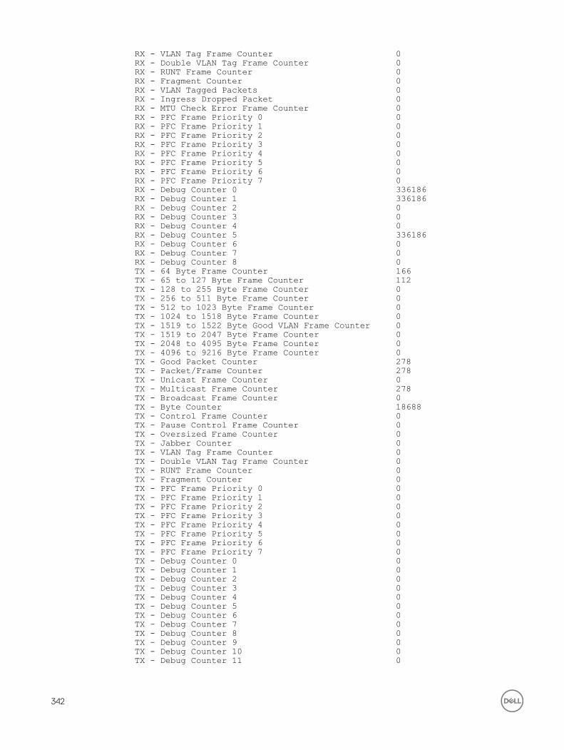
RX - VLAN Tag Frame Counter 0RX - Double VLAN Tag Frame Counter 0RX - RUNT Frame Counter 0RX - Fragment Counter 0RX - VLAN Tagged Packets 0RX - Ingress Dropped Packet 0RX - MTU Check Error Frame Counter 0RX - PFC Frame Priority 0 0RX - PFC Frame Priority 1 0RX - PFC Frame Priority 2 0RX - PFC Frame Priority 3 0RX - PFC Frame Priority 4 0RX - PFC Frame Priority 5 0RX - PFC Frame Priority 6 0RX - PFC Frame Priority 7 0RX - Debug Counter 0 336186RX - Debug Counter 1 336186RX - Debug Counter 2 0RX - Debug Counter 3 0RX - Debug Counter 4 0RX - Debug Counter 5 336186RX - Debug Counter 6 0RX - Debug Counter 7 0RX - Debug Counter 8 0TX - 64 Byte Frame Counter 166TX - 65 to 127 Byte Frame Counter 112TX - 128 to 255 Byte Frame Counter 0TX - 256 to 511 Byte Frame Counter 0TX - 512 to 1023 Byte Frame Counter 0TX - 1024 to 1518 Byte Frame Counter 0TX - 1519 to 1522 Byte Good VLAN Frame Counter 0TX - 1519 to 2047 Byte Frame Counter 0TX - 2048 to 4095 Byte Frame Counter 0TX - 4096 to 9216 Byte Frame Counter 0TX - Good Packet Counter 278TX - Packet/Frame Counter 278TX - Unicast Frame Counter 0TX - Multicast Frame Counter 278TX - Broadcast Frame Counter 0TX - Byte Counter 18688TX - Control Frame Counter 0TX - Pause Control Frame Counter 0TX - Oversized Frame Counter 0TX - Jabber Counter 0TX - VLAN Tag Frame Counter 0TX - Double VLAN Tag Frame Counter 0TX - RUNT Frame Counter 0TX - Fragment Counter 0TX - PFC Frame Priority 0 0TX - PFC Frame Priority 1 0TX - PFC Frame Priority 2 0TX - PFC Frame Priority 3 0TX - PFC Frame Priority 4 0TX - PFC Frame Priority 5 0TX - PFC Frame Priority 6 0TX - PFC Frame Priority 7 0TX - Debug Counter 0 0TX - Debug Counter 1 0TX - Debug Counter 2 0TX - Debug Counter 3 0TX - Debug Counter 4 0TX - Debug Counter 5 0TX - Debug Counter 6 0TX - Debug Counter 7 0TX - Debug Counter 8 0TX - Debug Counter 9 0TX - Debug Counter 10 0TX - Debug Counter 11 0
342

-------------------------unit: 0 port: 61 (interface Fo 1/60)Description Value
RX - IPV4 L3 Unicast Frame Counter 0RX - IPV4 L3 Routed Multicast Packets 0RX - IPV6 L3 Unicast Frame Counter 0RX - IPV6 L3 Routed Multicast Packets 0RX - Unicast Packet Counter 0RX - 64 Byte Frame Counter 0RX - 65 to 127 Byte Frame Counter 0RX - 128 to 255 Byte Frame Counter 0RX - 256 to 511 Byte Frame Counter 0RX - 512 to 1023 Byte Frame Counter 0RX - 1024 to 1518 Byte Frame Counter 0RX - 1519 to 1522 Byte Good VLAN Frame Counter 0RX - 1519 to 2047 Byte Frame Counter 0RX - 2048 to 4095 Byte Frame Counter 0RX - 4096 to 9216 Byte Frame Counter 0RX - Good Packet Counter 0RX - Packet/Frame Counter 0RX - Unicast Frame Counter 0RX - Multicast Frame Counter 0RX - Broadcast Frame Counter 0RX - Byte Counter 0RX - Control Frame Counter 0RX - Pause Control Frame Counter 0RX - Oversized Frame Counter 0RX - Jabber Frame Counter 0RX - VLAN Tag Frame Counter 0RX - Double VLAN Tag Frame Counter 0RX - RUNT Frame Counter 0RX - Fragment Counter 0RX - VLAN Tagged Packets 0RX - Ingress Dropped Packet 0RX - MTU Check Error Frame Counter 0RX - PFC Frame Priority 0 0RX - PFC Frame Priority 1 0RX - PFC Frame Priority 2 0RX - PFC Frame Priority 3 0RX - PFC Frame Priority 4 0RX - PFC Frame Priority 5 0RX - PFC Frame Priority 6 0RX - PFC Frame Priority 7 0RX - Debug Counter 0 0RX - Debug Counter 1 0RX - Debug Counter 2 0RX - Debug Counter 3 0RX - Debug Counter 4 0RX - Debug Counter 5 0RX - Debug Counter 6 0RX - Debug Counter 7 0RX - Debug Counter 8 0TX - 64 Byte Frame Counter 0TX - 65 to 127 Byte Frame Counter 0TX - 128 to 255 Byte Frame Counter 0TX - 256 to 511 Byte Frame Counter 0TX - 512 to 1023 Byte Frame Counter 0TX - 1024 to 1518 Byte Frame Counter 0TX - 1519 to 1522 Byte Good VLAN Frame Counter 0TX - 1519 to 2047 Byte Frame Counter 0TX - 2048 to 4095 Byte Frame Counter 0TX - 4096 to 9216 Byte Frame Counter 0TX - Good Packet Counter 0TX - Packet/Frame Counter 0
343

TX - Unicast Frame Counter 0TX - Multicast Frame Counter 0TX - Broadcast Frame Counter 0TX - Byte Counter 0TX - Control Frame Counter 0TX - Pause Control Frame Counter 0TX - Oversized Frame Counter 0TX - Jabber Counter 0TX - VLAN Tag Frame Counter 0TX - Double VLAN Tag Frame Counter 0TX - RUNT Frame Counter 0TX - Fragment Counter 0TX - PFC Frame Priority 0 0TX - PFC Frame Priority 1 0TX - PFC Frame Priority 2 0TX - PFC Frame Priority 3 0TX - PFC Frame Priority 4 0TX - PFC Frame Priority 5 0TX - PFC Frame Priority 6 0TX - PFC Frame Priority 7 0TX - Debug Counter 0 0TX - Debug Counter 1 0TX - Debug Counter 2 0TX - Debug Counter 3 0TX - Debug Counter 4 0TX - Debug Counter 5 0TX - Debug Counter 6 0TX - Debug Counter 7 0TX - Debug Counter 8 0TX - Debug Counter 9 0TX - Debug Counter 10 0TX - Debug Counter 11 0
Example (port-statistics)
Dell#show hardware stack-unit 0 unit 0 port-stats ena/ speed/ link auto STP lrn inter max loop port link duplex scan neg? state pause discrd ops face frame back xe0 up 10G FD SW Yes Forward None FA KR 11996 xe1 up 10G FD SW Yes Forward None FA KR 11996 xe2 up 10G FD SW Yes Forward None FA KR 11996 xe3 down 1G FD SW Yes Block RX None FA GMII 11996 xe4 up 10G FD SW Yes Forward None FA KR 11996 xe5 down 1G FD SW Yes Block RX None FA GMII 11996 xe6 up 10G FD SW Yes Forward None FA KR 11996 xe7 down 1G FD SW Yes Block RX None FA GMII 11996 xe8 down 10G FD SW No Block RX None FA SFI 11996 xe9 down 10G FD SW No Block RX None FA SFI 11996 xe10 up 10G FD SW No Forward None FA SFI 11996 xe11 up 10G FD SW No Forward None FA SFI 11996 Dell#
Example (register) Dell#show hardware stack-unit 0 unit 0 register0x0f180d34 ALTERNATE_EMIRROR_BITMAP_PARITY_CONTROL.ipipe0 = 0x000000010x0f180d35 ALTERNATE_EMIRROR_BITMAP_PARITY_STATUS_INTR.ipipe0 = 0x000000000x0f180d36 ALTERNATE_EMIRROR_BITMAP_PARITY_STATUS_NACK.ipipe0 = 0x00000000
344

0x0018070c ARB_EOP_DEBUG.ipipe0 = 0x000000000x00180312 ARB_RAM_DBGCTRL.ipipe0 = 0x000000000x03300000 ASF_PORT_SPEED.cpu0 = 0x000000000x03322000 ASF_PORT_SPEED.xe0 = 0x000000000x03326000 ASF_PORT_SPEED.xe1 = 0x000000000x0332a000 ASF_PORT_SPEED.xe2 = 0x000000070x0332e000 ASF_PORT_SPEED.xe3 = 0x000000000x03323000 ASF_PORT_SPEED.xe4 = 0x000000000x03327000 ASF_PORT_SPEED.xe5 = 0x000000000x0332b000 ASF_PORT_SPEED.xe6 = 0x000000000x0332f000 ASF_PORT_SPEED.xe7 = 0x000000000x03324000 ASF_PORT_SPEED.xe8 = 0x000000000x03328000 ASF_PORT_SPEED.xe9 = 0x000000000x0332c000 ASF_PORT_SPEED.xe10 = 0x000000000x03330000 ASF_PORT_SPEED.xe11 = 0x000000000x03325000 ASF_PORT_SPEED.xe12 = 0x000000000x03329000 ASF_PORT_SPEED.xe13 = 0x000000000x0332d000 ASF_PORT_SPEED.xe14 = 0x000000000x03331000 ASF_PORT_SPEED.xe15 = 0x000000000x03332000 ASF_PORT_SPEED.xe16 = 0x000000000x03336000 ASF_PORT_SPEED.xe17 = 0x000000000x0333a000 ASF_PORT_SPEED.xe18 = 0x000000000x0333e000 ASF_PORT_SPEED.xe19 = 0x000000000x03333000 ASF_PORT_SPEED.xe20 = 0x000000000x03337000 ASF_PORT_SPEED.xe21 = 0x000000000x0333b000 ASF_PORT_SPEED.xe22 = 0x000000000x0333f000 ASF_PORT_SPEED.xe23 = 0x000000000x03334000 ASF_PORT_SPEED.xe24 = 0x000000000x03338000 ASF_PORT_SPEED.xe25 = 0x000000000x0333c000 ASF_PORT_SPEED.xe26 = 0x000000000x03340000 ASF_PORT_SPEED.xe27 = 0x000000000x03335000 ASF_PORT_SPEED.xe28 = 0x000000000x03339000 ASF_PORT_SPEED.xe29 = 0x00000000!------------------ output truncated ---------------!
Example (unit details)
Dell#show hardware stack-unit 0 unit 0 details
******************************************************
The total no of FP & CSF Devices in the Card is 1The total no of FP Devices in the Card is 1The total no of CSF Devices in the Card is 0The number of ports in device 0 is - 12 The number of Hg ports in devices 0 is - -1 The CPU Port of the device is 0 The starting unit no the SWF in the device is 0 ******************************************************
bcmLinkMonStatusShow: The Current Link Status Is
Front End Link Status 0xea3000000000000000000000 Front End Port Present Status 0x000000000000000000000000 Back Plane Link Status 0x00000000
******************************************************
Link Status of all the ports in the Device - 0
The linkStatus of Front End Port 42 is TRUE The linkStatus of Front End Port 43 is TRUE The linkStatus of Front End Port 44 is TRUE The linkStatus of Front End Port 45 is FALSE The linkStatus of Front End Port 46 is TRUE The linkStatus of Front End Port 47 is FALSE The linkStatus of Front End Port 48 is TRUE The linkStatus of Front End Port 49 is FALSE The linkStatus of Front End Port 50 is FALSE The linkStatus of Front End Port 51 is FALSE
345

The linkStatus of Front End Port 52 is TRUE The linkStatus of Front End Port 53 is TRUE ******************************************************
*************************************************
ModPort Table for Device - 0For Destination Mod Id 0 Destination Port is 0 *************************************************Dell#
Example (Buffer-Info)
Dell# show hardware stack-unit 1 buffer unit 0 port 1 priority-group 0 buffer-info
----- Buffer Accounting Stats for Unit 0 Port 1 priority-group 0 ----- Maximum Shared Limit: 0 Default Packet Buffer allocate for the priority-group: 61440 Accounted Packet Buffer: 0
Example (buffer) Dell#show hardware stack-unit 0 buffer total-buffer ------ Buffer Details for Stack-Unit 0 ------Total Buffers allocated per Stack-Unit 19456Dell#
Example (Queue2/Buffer-Info)
Dell#show hardware stack-unit 1 buffer unit 0 interface all queue 6 buffer-info Buffer Stats for Front End Ports ================================ ----- Buffer Stats for Interface Te 1/1 Queue 6 -----Maximum Shared Limit: 7667Default Packet Buffer allocate for the Queue: 8Used Packet Buffer: 0----- Buffer Stats for Interface Te 1/2 Queue 6 -----Maximum Shared Limit: 7667Default Packet Buffer allocate for the Queue: 8Used Packet Buffer: 0----- Buffer Stats for Interface Te 1/3 Queue 6 -----Maximum Shared Limit: 7667Default Packet Buffer allocate for the Queue: 8Used Packet Buffer: 0----- Buffer Stats for Interface Te 1/4 Queue 6 -----Maximum Shared Limit: 7667Default Packet Buffer allocate for the Queue: 8Used Packet Buffer: 0----- Buffer Stats for Interface Te 1/5 Queue 6 -----Maximum Shared Limit: 7667Default Packet Buffer allocate for the Queue: 8Used Packet Buffer: 0----- Buffer Stats for Interface Te 1/6 Queue 6 -----Maximum Shared Limit: 7667Default Packet Buffer allocate for the Queue: 8Used Packet Buffer: 0<output truncated for brevity>
Related Commands show interfaces stack-unit — displays information on all interfaces on a specific stack member.
show processes cpu — displays CPU usage information based on running processes.
show system — displays the current status of all stack members or a specific member.
346

show hardware system-flowDisplay Layer 2 ACL or QoS data for the selected stack member and stack member port-pipe.
Syntax show hardware system-flow layer2 stack-unit 0–5 port-set 0–0 [counters]Parameters
acl | qos For the selected stack member and stack member port-pipe, display which system flow entry the packet hits and what queue the packet takes as it dumps the raw system flow tables.
stack-unit 0–5 Enter the keywords stack-unit then 0 to 5 to select a stack member ID.
port-set 0–0 [counters]
Enter the keywords port-set with a port-pipe number—0.
(OPTIONAL) Enter the keyword counters to display hit counters for the selected
ACL or QoS option.
Defaults none
Command Modes EXEC Privilege
Supported Modes All Modes
Command HistoryVersion Description
9.4(0.0) Supported on the FN I/O Aggregator.
Example Dell#show hardware system-flow layer2 stack-unit 0 port-set 0 counters --------------------------------------------------------------------------- EntryId Description #HITS--------------------------------------------------------------------------- 767 LLDP BPDU Redirects 2611 765 LACP traffic Redirects 250 763 ARP Reply Redirects 0 762 Slow Protocol Drops 1155 758 OSPFv3 Multicast [33:33:00:00:00:06] 0 759 OSPFv3 Multicast [33:33:00:00:00:05] 0 756 GRAT ARP 0 711 VLT ARP Replies for Peer 0 710 ICL Hellos 0 709 ICL MAC SYNC Frames 0 708 VLT STP BPDUs Tunneled 0 707 VLT IGMP Sync Frames 0 706 VLT ARP Replies Tunneled 0 705 VLT L2PM Sync Frames 0 704 VLT ARP Sync Frames 0 703 VLT IPM Sync Frames 0 701 VLT NDPM Sync Frames 0 699 VLT TTL1 Packets Tunneled 0 698 VLT Dyn Client pkts 0 697 VLT PIM Sync Frames 0 696 VLT MRTM Sync Frames 0 695 VLT SMUX Sync Frames 0 693 DROP Cases 0 509 BGP_SPORT PACKETS 0 508 BGP_DPORT PACKETS 0 507 MSDP_SPORT PACKETS 0 506 MSDP_DPORT PACKETS 0 510 IGMP PACKETS WITH IP OPTIONS 26 505 FP Entry for OSPF IPv4 Unicast 0
347

504 FP Entry for RIP IPv4 Unicast 0 503 FP Entry for OSPF IPv6 Unicast 0 502 FP Entry for NA IPv6 0 501 FP Entry for RA IPv6 0 500 FP Entry for NS IPv6 4 499 FP Entry for RS IPv6 8 498 FP Entry for MLD IPv6 0 497 L3 CPU Bound Traffic ClassId 2 to Q5 0 496 FP Entry for ICMP CPU Terminated IPv6 0 495 FP Entry for ICMP IPv6 0 494 L3 Term Traffic ClassID 1 to Q6 0 493 Unknown MCAST Packets 0 492 224.0.0.x 24 491 224.0.1.1 0 490 SIMPLEMUX - VLAN Flood Restrict Entry 0 249 IGMP Packets 26 147 MULTICAST KNOWN TTL1 0 145 L2_DST_HIT+BC MAC+VLAN 4095 0 144 L2_DST_HIT+BC MAC 0 773 Known & Unknown L3UC Packets 0 772 Unknown L2MC Packets 26 771 Known and Unknown L3MC Packets 0 770 L2UCAST + L2DLF Packets 0 769 L2BCASTPackets 0Dell#
Example (non-counters)
Dell#show hardware system-flow layer2 stack-unit 0 port-set 0
############## FP Entry for redirecting STP BPDU to CPU Port ################EID 2048: gid=1, slice=15, slice_idx=0x00, prio=0x800, flags=0x82, Installed tcam: color_indep=0, higig=0, higig_mask=0, KEY=0x00000000 00000000 00000000 0180c200 00000000 00000000 00000000, FPF4=0x00 MASK=0x00000000 00000000 00000000 ffffffff ffff0000 00000000 00000000, 0x00 action={act=Drop, param0=0(0x00), param1=0(0x00)}, action={act=CosQCpuNew, param0=7(0x07), param1=0(0x00)}, action={act=CopyToCpu, param0=0(0x00), param1=0(0x00)}, action={act=UpdateCounter, param0=1(0x01), param1=0(0x00)}, meter=NULL, counter={idx=0, mode=0x01, entries=1}
################ FP Entry for redirecting LLDP BPDU to RSM ################EID 2047: gid=1, slice=15, slice_idx=0x01, prio=0x7ff, flags=0x82, Installed tcam: color_indep=0, higig=0, higig_mask=0, KEY=0x00000000 00000000 00000000 0180c200 000e0000 00000000 00000000, FPF4=0x00 MASK=0x00000000 00000000 00000000 ffffffff ffff0000 00000000 00000000, 0x00action={act=Drop, param0=0(0x00), param1=0(0x00)}, action={act=CosQCpuNew, param0=7(0x07), param1=0(0x00)}, action={act=CopyToCpu, param0=0(0x00), param1=0(0x00)}, action={act=UpdateCounter, param0=1(0x01), param1=0(0x00)}, meter=NULL, counter={idx=1, mode=0x01, entries=1}
############## FP Entry for redirecting LACP traffic to CPU Port ############
348

EID 2045: gid=1, slice=15, slice_idx=0x02, prio=0x7fd, flags=0x82, Installed tcam: color_indep=0, higig=0, higig_mask=0, KEY=0x00000000 00000000 00000000 0180c200 00020000 00000000 00000000, FPF4=0x00 MASK=0x00000000 00000000 00000000 ffffffff ffff0000 00000000 00000000, 0x00 action={act=Drop, param0=0(0x00), param1=0(0x00)}, action={act=CosQCpuNew, param0=7(0x07), param1=0(0x00)}, action={act=CopyToCpu, param0=0(0x00), param1=0(0x00)}, action={act=UpdateCounter, param0=1(0x01), param1=0(0x00)}, meter=NULL, counter={idx=2, mode=0x01, entries=1}
################# FP Entry for redirecting GVRP traffic to RSM ###########EID 2044: gid=1, slice=15, slice_idx=0x03, prio=0x7fc, flags=0x82, Installed tcam: color_indep=0, higig=0, higig_mask=0, KEY=0x00000000 00000000 00000000 0180c200 00210000 00000000 00000000, FPF4=0x00 MASK=0x00000000 00000000 00000000 ffffffff ffff0000 00000000 00000000, 0x00 action={act=Drop, param0=0(0x00), param1=0(0x00)}, action={act=CosQCpuNew, param0=7(0x07), param1=0(0x00)}, action={act=CopyToCpu, param0=0(0x00), param1=0(0x00)}, action={act=UpdateCounter, param0=1(0x01), param1=0(0x00)}, meter=NULL, counter={idx=3, mode=0x01, entries=1}
################# FP Entry for redirecting ARP Replies to RSM #############EID 2043: gid=1, slice=15, slice_idx=0x04, prio=0x7fb, flags=0x82, Installed tcam: color_indep=0, higig=0, higig_mask=0, KEY=0x00000000 00000000 00000000 00000000 00000000 00000806 00001600, FPF4=0x00 MASK=0x00000000 00000000 00000000 00000000 00000000 0000ffff 00001600, 0x00 action={act=Drop, param0=0(0x00), param1=0(0x00)}, action={act=CosQCpuNew, param0=6(0x06), param1=0(0x00)}, action={act=CopyToCpu, param0=0(0x00), param1=0(0x00)}, action={act=UpdateCounter, param0=1(0x01), param1=0(0x00)},!--------- output truncated -----------------!
show hardware buffer interfaceDisplay buffer statistics for a specific interface.
Syntax show hardware buffer inteface interface{priority-group { id | all } | queue { id| all} ] buffer-info
Parametersinterface interface Enter any of the following keywords and slot/port or number information:
• For a 10-Gigabit Ethernet interface, enter the keyword TenGigabitEthernet then the slot/port information.
349

• For a 40-Gigabit Ethernet interface, enter the keyword fortyGigE then the slot/port information.
priority-group Identifier of the priority group in the range of 0 to 7.
queue Enter the keyword queue followed by id for specific queue or keyword all.
buffer-info To display total buffer information for the interface, enter the keywords buffer-info.
Command Modes EXEC
EXEC Privilege
Command HistoryVersion Description
9.8(0.0) Introduced on the M I/O Aggregator and FN I/O Aggregator.
Example displaying total-buffer information for the interface
Dell# show hardware buffer interface tengigabitethernet 1/1 buffer-info----- Buffer Stats for Interface Te 1/1 ----- Maximum Shared Limit for the Interface: 38336 Default Packet Buffer allocate for the Interface: 120 Used Packet Buffer for the Interface: 0
Example displaying priority-group range
Dell#show hardware buffer interface tengigabitethernet 1/1 priority-group 0 buffer-info----- Buffer stats for unit: 0 port: 1 (interface Te 1/1) -----------------------------------------------------------------------------PG# PRIORITIES ALLOTED (CELLS) COUNTER (CELLS) MIN SHARED MODE HDRM MIN SHARED HDRM------------------------------------------------------------------------0 - 61440 0 STATIC 174 0 0 0
Dell#
Example displaying queue range
Dell#show hardware buffer interface tengigabitethernet 1/1 queue all buffer-info----- Buffer Stats for Interface Te 1/1 Queue 0 ----- Maximum Shared Limit: 29514 Default Packet Buffer allocate for the Queue: 8 Used Packet Buffer: 0----- Buffer Stats for Interface Te 1/1 Queue 1 ----- Maximum Shared Limit: 29514 Default Packet Buffer allocate for the Queue: 8 Used Packet Buffer: 0----- Buffer Stats for Interface Te 1/1 Queue 2 ----- Maximum Shared Limit: 29514 Default Packet Buffer allocate for the Queue: 8 Used Packet Buffer: 0----- Buffer Stats for Interface Te 1/1 Queue 3 ----- Maximum Shared Limit: 29514 Default Packet Buffer allocate for the Queue: 8 Used Packet Buffer: 0----- Buffer Stats for Interface Te 1/1 Queue 4 ----- Maximum Shared Limit: 29514 Default Packet Buffer allocate for the Queue: 8 Used Packet Buffer: 0----- Buffer Stats for Interface Te 1/1 Queue 5 ----- Maximum Shared Limit: 29514 Default Packet Buffer allocate for the Queue: 8 Used Packet Buffer: 0
350

----- Buffer Stats for Interface Te 1/1 Queue 6 ----- Maximum Shared Limit: 29514 Default Packet Buffer allocate for the Queue: 8 Used Packet Buffer: 0----- Buffer Stats for Interface Te 1/1 Queue 7 ----- Maximum Shared Limit: 29514 Default Packet Buffer allocate for the Queue: 8 Used Packet Buffer: 0----- Buffer Stats for Interface Te 1/1 Queue 8 ----- Maximum Shared Limit: 29514 Default Packet Buffer allocate for the Queue: 8 Used Packet Buffer: 0----- Buffer Stats for Interface Te 1/1 Queue 9 ----- Maximum Shared Limit: 29514 Default Packet Buffer allocate for the Queue: 8 Used Packet Buffer: 0----- Buffer Stats for Interface Te 1/1 Queue 10 ----- Maximum Shared Limit: 29514 Default Packet Buffer allocate for the Queue: 8 Used Packet Buffer: 0----- Buffer Stats for Interface Te 1/1 Queue 11 ----- Maximum Shared Limit: 29514 Default Packet Buffer allocate for the Queue: 8
<output truncated for brevity>
show hardware counters interface interfaceDisplay the counter information for a specific interface.
Syntax show hardware counters interface interfaceParameters
counters Enter the keywords counters to display counter value for the specified stack-
member the port-pipe.
interface interface Enter any of the following keywords and slot/port or number information:
• For a 10-Gigabit Ethernet interface, enter the keyword TenGigabitEthernet then the slot/port information.
• For a 40-Gigabit Ethernet interface, enter the keyword fortyGigE then the slot/port information.
Defaults none
Command Modes• EXEC
• EXEC Privilege
Command History This guide is platform-specific. For command information about other platforms, refer to the relevant Dell Networking OS Command Line Reference Guide.
The following is a list of the Dell Networking OS version history for this command.
Version Description
9.8(0.0) Introduced on the FN I/O Aggregator.
351

Example Dell#show hardware counters interfac tengigabitethernet 5/1unit: 0 port: 2 (interface Te 5/1)Description Value
RX - IPV4 L3 Unicast Frame Counter 0RX - IPV4 L3 Routed Multicast Packets 0RX - IPV6 L3 Unicast Frame Counter 0RX - IPV6 L3 Routed Multicast Packets 0RX - Unicast Packet Counter 0RX - 64 Byte Frame Counter 0RX - 65 to 127 Byte Frame Counter 0RX - 128 to 255 Byte Frame Counter 0RX - 256 to 511 Byte Frame Counter 0RX - 512 to 1023 Byte Frame Counter 0RX - 1024 to 1518 Byte Frame Counter 0RX - 1519 to 1522 Byte Good VLAN Frame Counter 0RX - 1519 to 2047 Byte Frame Counter 0RX - 2048 to 4095 Byte Frame Counter 0RX - 4096 to 9216 Byte Frame Counter 0RX - Good Packet Counter 0RX - Packet/Frame Counter 0RX - Unicast Frame Counter 0RX - Multicast Frame Counter 0RX - Broadcast Frame Counter 0RX - Byte Counter 0RX - Control Frame Counter 0RX - Pause Control Frame Counter 0RX - Oversized Frame Counter 0RX - Jabber Frame Counter 0RX - VLAN Tag Frame Counter 0RX - Double VLAN Tag Frame Counter 0RX - RUNT Frame Counter 0RX - Fragment Counter 0RX - VLAN Tagged Packets 0RX - Ingress Dropped Packet 0RX - MTU Check Error Frame Counter 0RX - PFC Frame Priority 0 0RX - PFC Frame Priority 1 0RX - PFC Frame Priority 2 0RX - PFC Frame Priority 3 0RX - PFC Frame Priority 4 0RX - PFC Frame Priority 5 0RX - PFC Frame Priority 6 0RX - PFC Frame Priority 7 0RX - Debug Counter 0 0RX - Debug Counter 1 0RX - Debug Counter 2 0<output truncated for brevity>
show hardware stack-unit buffer-stats-snapshot (Total Buffer Information)View the buffer statistics tracking resource information depending on the type of buffer information, such as device-level details, port-level counters, queue-based snapshots, or priority group-level snapshot in the egress and ingress direction of traffic.
Syntax show hardware stack-unit {id} buffer-stats-snapshot unit {id} resource interface all {priority-group { id | all } | queue { ucast{id | all}{ mcast {id | all} | all}
352

Parametersstack-unit stack-unit-number
Unique ID of the stack unit to select a particular stack member and then enter one of the following command options to display a collection of data based on the option entered. The range is from 0 to 11.
buffer-stats-snapshot unit number
Display the historical snapshot of buffer statistical values unit Enter the keyword unit along with a port-pipe number. The range is from 0 to 0.
buffer-info buffer-info Displays total buffer information for a group, where x can be one of the following:
• All - Displays ingress and egress device, port, and queue snapshots
• Interface all queue {all} - egress queue-level snapshot for both unicast and multicast packets
• Interface all queue ucast {id | all} - egress queue-level snapshot for unicast packets only
• Interface all queue mcast {id | all} - egress queue-level snapshot for multicast packets only
• Interface all prio-group {id | all} - ingress priority-group level snapshot
Command Modes EXEC
EXEC Privilege
Command HistoryVersion Description
9.8(0.0) Introduced on the MI/O Aggregator, and FN I/O Aggregator.
Usage Information The following information is displayed based on the buffer-info type, such as device-level details, queue-based snapshots, or priority group-level snapshot in the egress and ingress direction of traffic:
• Device-ingress – Displays total buffer accounting usage for the unit.
• Device-egress –Display total buffer usage for the unit, total multicast buffer usage for the unit and also on per-service-pool basis. Counters will be displayed for the 2 service-pools – one for normal traffic and other for DCB traffic.
When the buffer-stats-snapshot is disabled, the following informational message is displayed when you run the show command: %Info: Buffer-stats-snapshot feature is disabled.
Example Dell#show hardware stack-unit 1 buffer-stats-snapshot unit 3 resource interface all queue mcast 3Unit 1 unit: 3 port: 1 (interface Fo 1/144)---------------------------------------Q# TYPE Q# TOTAL BUFFERED CELLS---------------------------------------MCAST 3 0
Unit 1 unit: 3 port: 5 (interface Fo 1/148)---------------------------------------Q# TYPE Q# TOTAL BUFFERED CELLS---------------------------------------MCAST 3 0
Unit 1 unit: 3 port: 9 (interface Fo 1/152)---------------------------------------
353

Q# TYPE Q# TOTAL BUFFERED CELLS---------------------------------------MCAST 3 0
Unit 1 unit: 3 port: 13 (interface Fo 1/156)---------------------------------------Q# TYPE Q# TOTAL BUFFERED CELLS---------------------------------------MCAST 3 0
Unit 1 unit: 3 port: 17 (interface Fo 1/160)---------------------------------------Q# TYPE Q# TOTAL BUFFERED CELLS---------------------------------------MCAST 3 0
Unit 1 unit: 3 port: 21 (interface Fo 1/164)---------------------------------------Q# TYPE Q# TOTAL BUFFERED CELLS---------------------------------------MCAST 3 0
Unit 1 unit: 3 port: 25 (interface Fo 1/168)---------------------------------------Q# TYPE Q# TOTAL BUFFERED CELLS---------------------------------------MCAST 3 0
Unit 1 unit: 3 port: 29 (interface Fo 1/172)---------------------------------------Q# TYPE Q# TOTAL BUFFERED CELLS---------------------------------------MCAST 3 0
Unit 1 unit: 3 port: 33 (interface Fo 1/176)---------------------------------------Q# TYPE Q# TOTAL BUFFERED CELLS---------------------------------------MCAST 3 0
Unit 1 unit: 3 port: 37 (interface Fo 1/180)---------------------------------------Q# TYPE Q# TOTAL BUFFERED CELLS---------------------------------------
show hardware buffer-stats-snapshotDisplays buffer statistics tracking resource information for a specific interface.
Syntax Dell#show hardware stack-unit <id> buffer-stats-snapshot unit <id> resource x
Parametersbuffer-info buffer-info Displays total buffer information for a group, where x can be one of the
following:
• All - Displays ingress and egress device, port, and queue snapshots
• Interface all queue {all} - egress queue-level snapshot for both unicast and multicast packets
354

• Interface all queue ucast {id | all} - egress queue-level snapshot for unicast packets only
• Interface all queue mcast {id | all} - egress queue-level snapshot for multicast packets only
• Interface all prio-group {id | all} - ingress priority-group level snapshot
buffer-stats-snapshot unit number
Display the historical snapshot of buffer statistical values unit Enter the keyword unit along with a port-pipe number. The range is from 0 to 0.
Command Modes EXEC
EXEC Privilege
Command HistoryVersion Description
9.8(0.0) Introduced on the M I/O Aggregator and the FN I/O Aggregator.
Usage Information <Interface><slot/port>-Queue ucast/mcast — Displays the total unicast/multicast buffer
usage on per-port per-queue basis. For CPU port, counters for queues 0 to11 displays and there is no differentiation between unicast and multicast queues.
Example displaying egress queue-level snapshot for both unicast and multicast packets for the specific interface
Dell# show hardware buffer-stats-snapshot resource interface fortyGigE 1/1 queue allUnit 1 unit: 0 port: 1 (interface Fo 1/1)---------------------------------------Q# TYPE Q# TOTAL BUFFERED CELLS---------------------------------------UCAST 0 0UCAST 1 0UCAST 2 0UCAST 3 0UCAST 4 0UCAST 5 0UCAST 6 0UCAST 7 0UCAST 8 0UCAST 9 0UCAST 10 0UCAST 11 0MCAST 0 0MCAST 1 0MCAST 2 0MCAST 3 0MCAST 4 0MCAST 5 0MCAST 6 0MCAST 7 0MCAST 8 0
Example displaying egress queue-level snapshot for unicast packets for the specific interface
Del#show hardware buffer-stats-snapshot resource interface fortyGigE 0/0 queue ucast 10 Unit 0 unit: 0 port: 1 (interface Fo 0/0)---------------------------------------Q# TYPE Q# TOTAL BUFFERED CELLS---------------------------------------UCAST 10 0Dell#show hardware buffer-stats-snapshot resource interface fortyGigE 0/0 queue ucast all
355

Unit 0 unit: 0 port: 1 (interface Fo 0/0)---------------------------------------Q# TYPE Q# TOTAL BUFFERED CELLS---------------------------------------UCAST 0 0UCAST 1 0UCAST 2 0UCAST 3 0UCAST 4 0UCAST 5 0UCAST 6 0UCAST 7 0UCAST 8 0UCAST 9 0UCAST 10 0UCAST 11 0
Example displaying egress queue-level snapshot for multicast packets for the specific interface
Dell#show hardware buffer-stats-snapshot resource interface fortyGigE 0/0 queue mcast 3Unit 1 unit: 0 port: 1 (interface Fo 0/0)---------------------------------------Q# TYPE Q# TOTAL BUFFERED CELLS---------------------------------------MCAST 3 0Dell#show hardware buffer-stats-snapshot resource interface fortyGigE 0/0 queue mcast all
Unit 0 unit: 0 port: 1 (interface Fo 0/0)---------------------------------------Q# TYPE Q# TOTAL BUFFERED CELLS---------------------------------------MCAST 0 0MCAST 1 0MCAST 2 0MCAST 3 0MCAST 4 0MCAST 5 0MCAST 6 0MCAST 7 0MCAST 8 0
Example displaying ingress priority-group level snapshot for the specific interface
Dell#show hardware buffer-stats-snapshot resource interface fortyGigE 1/1 priority-group 7
Unit 1 unit: 0 port: 1 (interface Fo 1/1)---------------------------------------PG# SHARED CELLS HEADROOM CELLS---------------------------------------7 0 0
Dell#show hardware buffer-stats-snapshot resource interface fortyGigE 1/1 priority-group all
Unit 1 unit: 0 port: 1 (interface Fo 1/1)---------------------------------------PG# SHARED CELLS HEADROOM CELLS---------------------------------------0 0 01 0 02 0 03 0 04 0 05 0 0
356

6 0 07 0 0Dell#show hardware buffer-stats-snapshot resource interface fortyGigE 0/0 priority-group 7
Unit 0 unit: 0 port: 1 (interface Fo 0/0)---------------------------------------PG# SHARED CELLS HEADROOM CELLS---------------------------------------7 0 0
Dell#show hardware buffer-stats-snapshot resource interface fortyGigE 0/0 priority-group all
Unit 0 unit: 0 port: 1 (interface Fo 0/0)---------------------------------------PG# SHARED CELLS HEADROOM CELLS---------------------------------------0 0 01 0 02 0 03 0 04 0 05 0 06 0 07 0 0
show hardware dropsDisplays internal drops on the specified interface or for a range of interface.
Syntax show hardware drops interface interface
Parametersinterface Enter any of the following keywords and slot/port or slot/port-range or number
information:
• For a 10-Gigabit Ethernet interface, enter the keyword TenGigabitEthernet then the slot/port information.
• For a 40-Gigabit Ethernet interface, enter the keyword fortyGigE then the slot/port information.
drops Enter the keyword drops to display internal drops.
Command Modes EXEC
EXEC Privilege
Command History This guide is platform-specific. For command information about other platforms, refer to the relevant Dell Networking OS Command Line Reference Guide.
The following is a list of the Dell Networking OS version history for this command.
357

Version Description
9.8(0.0) Introduced on the M I/O Aggregator and the FN I/O Aggregator.
Example displaying internal drops for the specific interface
Dell#show hardware drops interface tengigabitethernet 2/1
Drops in Interface Te 2/1: --- Ingress Drops ---Ingress Drops : 0IBP CBP Full Drops : 0PortSTPnotFwd Drops : 0IPv4 L3 Discards : 0Policy Discards : 0Packets dropped by FP : 0(L2+L3) Drops : 0Port bitmap zero Drops : 0Rx VLAN Drops : 0 --- Ingress MAC counters---Ingress FCSDrops : 0Ingress MTUExceeds : 0 --- MMU Drops ---Ingress MMU Drops : 0HOL DROPS(TOTAL) : 0HOL DROPS on COS0 : 0HOL DROPS on COS1 : 0HOL DROPS on COS2 : 0HOL DROPS on COS3 : 0HOL DROPS on COS4 : 0HOL DROPS on COS5 : 0HOL DROPS on COS6 : 0HOL DROPS on COS7 : 0HOL DROPS on COS8 : 0HOL DROPS on COS9 : 0HOL DROPS on COS10 : 0HOL DROPS on COS11 : 0HOL DROPS on COS12 : 0HOL DROPS on COS13 : 0HOL DROPS on COS14 : 0HOL DROPS on COS15 : 0HOL DROPS on COS16 : 0HOL DROPS on COS17 : 0TxPurge CellErr : 0Aged Drops : 0 --- Egress MAC counters---Egress FCS Drops : 0 --- Egress FORWARD PROCESSOR Drops ---IPv4 L3UC Aged & Drops : 0TTL Threshold Drops : 0INVALID VLAN CNTR Drops : 0L2MC Drops : 0PKT Drops of ANY Conditions : 0Hg MacUnderflow : 0TX Err PKT Counter : 0 --- Error counters---Internal Mac Transmit Errors : 0Unknown Opcodes : 0Internal Mac Receive Errors : 0
358

AInternet Control Message Protocol (ICMP) Message TypesThis chapter lists and describes the possible ICMP message type resulting from a ping. The first three columns list the possible symbol or type/code. For example, you would receive a ! or 03 as an echo reply from your ping.
Table 1. ICMP Messages and Their Definitions
Symbol Type Code Description Query Error
. Timeout (no reply)
! 0 3 echo reply .
U 3 destination unreachable:
0 network unreachable .
1 host unreachable .
2 protocol unreachable .
3 port unreachable .
4 fragmentation needed but don’t fragment bit set
.
5 source route failed .
6 destination network unknown .
7 destination host unknown .
8 source host isolated (obsolete) .
9 destination network administratively prohibited
.
10 destination host administratively prohibited .
11 network unreachable for TOS .
12 host unreachable for TOS .
13 communication administratively prohibited by filtering
.
14 host precedence violation .
15 precedence cutoff in effect .
C 4 0 source quench .
5 redirect .
0 redirect for network .
1 redirect for host .
2 redirect for type-of-service and network .
3 redirect for type-of-service and host .
359

Symbol Type Code Description Query Error
8 0 echo request .
9 0 router advertisement .
10 0 router solicitation .
& 11 time exceeded:
0 time-to-live equals 0 during transit .
1 time-to-live equals 0 during reassembly .
12 parameter problem:
1 IP header bad (catchall error) .
2 required option missing .
13 0 timestamp request .
14 0 timestamp reply .
15 0 information request (obsolete) .
16 0 information reply (obsolete) .
17 0 address mask request .
18 0 address mask reply .
360